EP3117207B1 - Ultrasonic-pulse-echo flaw inspection at a high testing speed on thin-walled pipes in particular - Google Patents
Ultrasonic-pulse-echo flaw inspection at a high testing speed on thin-walled pipes in particular Download PDFInfo
- Publication number
- EP3117207B1 EP3117207B1 EP15708553.1A EP15708553A EP3117207B1 EP 3117207 B1 EP3117207 B1 EP 3117207B1 EP 15708553 A EP15708553 A EP 15708553A EP 3117207 B1 EP3117207 B1 EP 3117207B1
- Authority
- EP
- European Patent Office
- Prior art keywords
- time
- test object
- ultrasonic
- echo signal
- sound
- Prior art date
- Legal status (The legal status is an assumption and is not a legal conclusion. Google has not performed a legal analysis and makes no representation as to the accuracy of the status listed.)
- Active
Links
Images


Classifications
-
- G—PHYSICS
- G01—MEASURING; TESTING
- G01N—INVESTIGATING OR ANALYSING MATERIALS BY DETERMINING THEIR CHEMICAL OR PHYSICAL PROPERTIES
- G01N29/00—Investigating or analysing materials by the use of ultrasonic, sonic or infrasonic waves; Visualisation of the interior of objects by transmitting ultrasonic or sonic waves through the object
- G01N29/04—Analysing solids
- G01N29/043—Analysing solids in the interior, e.g. by shear waves
-
- G—PHYSICS
- G01—MEASURING; TESTING
- G01N—INVESTIGATING OR ANALYSING MATERIALS BY DETERMINING THEIR CHEMICAL OR PHYSICAL PROPERTIES
- G01N29/00—Investigating or analysing materials by the use of ultrasonic, sonic or infrasonic waves; Visualisation of the interior of objects by transmitting ultrasonic or sonic waves through the object
- G01N29/04—Analysing solids
- G01N29/11—Analysing solids by measuring attenuation of acoustic waves
-
- G—PHYSICS
- G01—MEASURING; TESTING
- G01N—INVESTIGATING OR ANALYSING MATERIALS BY DETERMINING THEIR CHEMICAL OR PHYSICAL PROPERTIES
- G01N29/00—Investigating or analysing materials by the use of ultrasonic, sonic or infrasonic waves; Visualisation of the interior of objects by transmitting ultrasonic or sonic waves through the object
- G01N29/22—Details, e.g. general constructional or apparatus details
- G01N29/221—Arrangements for directing or focusing the acoustical waves
-
- G—PHYSICS
- G01—MEASURING; TESTING
- G01N—INVESTIGATING OR ANALYSING MATERIALS BY DETERMINING THEIR CHEMICAL OR PHYSICAL PROPERTIES
- G01N29/00—Investigating or analysing materials by the use of ultrasonic, sonic or infrasonic waves; Visualisation of the interior of objects by transmitting ultrasonic or sonic waves through the object
- G01N29/22—Details, e.g. general constructional or apparatus details
- G01N29/24—Probes
- G01N29/2487—Directing probes, e.g. angle probes
-
- G—PHYSICS
- G01—MEASURING; TESTING
- G01N—INVESTIGATING OR ANALYSING MATERIALS BY DETERMINING THEIR CHEMICAL OR PHYSICAL PROPERTIES
- G01N29/00—Investigating or analysing materials by the use of ultrasonic, sonic or infrasonic waves; Visualisation of the interior of objects by transmitting ultrasonic or sonic waves through the object
- G01N29/36—Detecting the response signal, e.g. electronic circuits specially adapted therefor
-
- G—PHYSICS
- G01—MEASURING; TESTING
- G01N—INVESTIGATING OR ANALYSING MATERIALS BY DETERMINING THEIR CHEMICAL OR PHYSICAL PROPERTIES
- G01N29/00—Investigating or analysing materials by the use of ultrasonic, sonic or infrasonic waves; Visualisation of the interior of objects by transmitting ultrasonic or sonic waves through the object
- G01N29/36—Detecting the response signal, e.g. electronic circuits specially adapted therefor
- G01N29/38—Detecting the response signal, e.g. electronic circuits specially adapted therefor by time filtering, e.g. using time gates
-
- G—PHYSICS
- G01—MEASURING; TESTING
- G01N—INVESTIGATING OR ANALYSING MATERIALS BY DETERMINING THEIR CHEMICAL OR PHYSICAL PROPERTIES
- G01N29/00—Investigating or analysing materials by the use of ultrasonic, sonic or infrasonic waves; Visualisation of the interior of objects by transmitting ultrasonic or sonic waves through the object
- G01N29/36—Detecting the response signal, e.g. electronic circuits specially adapted therefor
- G01N29/40—Detecting the response signal, e.g. electronic circuits specially adapted therefor by amplitude filtering, e.g. by applying a threshold or by gain control
-
- G—PHYSICS
- G01—MEASURING; TESTING
- G01N—INVESTIGATING OR ANALYSING MATERIALS BY DETERMINING THEIR CHEMICAL OR PHYSICAL PROPERTIES
- G01N29/00—Investigating or analysing materials by the use of ultrasonic, sonic or infrasonic waves; Visualisation of the interior of objects by transmitting ultrasonic or sonic waves through the object
- G01N29/44—Processing the detected response signal, e.g. electronic circuits specially adapted therefor
- G01N29/4463—Signal correction, e.g. distance amplitude correction [DAC], distance gain size [DGS], noise filtering
-
- G—PHYSICS
- G01—MEASURING; TESTING
- G01N—INVESTIGATING OR ANALYSING MATERIALS BY DETERMINING THEIR CHEMICAL OR PHYSICAL PROPERTIES
- G01N2291/00—Indexing codes associated with group G01N29/00
- G01N2291/04—Wave modes and trajectories
- G01N2291/044—Internal reflections (echoes), e.g. on walls or defects
-
- G—PHYSICS
- G01—MEASURING; TESTING
- G01N—INVESTIGATING OR ANALYSING MATERIALS BY DETERMINING THEIR CHEMICAL OR PHYSICAL PROPERTIES
- G01N2291/00—Indexing codes associated with group G01N29/00
- G01N2291/04—Wave modes and trajectories
- G01N2291/056—Angular incidence, angular propagation
Definitions
- the testing speed of ultrasonic test objects with an oblique angle of sound incidence in pulse-echo technology is linked to the sound field expansion across the direction of sound propagation of the ultrasonic field emitted by the ultrasonic transducer.
- WO 2004/005913 A1 discloses coupling an ultrasonic testing head to a spot weld.
- US 5 431 054 A1 discloses an ultrasonic flaw detection device with a transmitting transducer and a plurality of received transducers.
- the method according to the invention for ultrasonic testing according to the pulse-echo method has a step of oblique incidence of an ultrasonic pulse into a test object via a sound incidence surface by using an ultrasonic transducer.
- "Oblique" in the sense of the invention means that the main direction of propagation of the sound emitted from the ultrasonic transducer forms a non-right angle with the sound incidence surface, and thus the sound has a propagation component in the test object that is perpendicular to the plumb line to the input surface.
- the angle of incidence set in the step of oblique sound incidence is selected so that the main direction of propagation of the ultrasonic pulse assumes an angle to the sound incidence surface in the range of 40° to 50°, for example, approximately or exactly 45.0°, immediately after passing through the input surface.
- phased array test heads may preferably also be used.
- an evaluation of the amplitude characteristic of the echo signal over time in a predefined defect expectation interval of time comprises, for example, comparison of the amplitude with a predefined threshold value to detect a defect in the test object, for example, when the threshold value is exceeded.
- the step of evaluation comprises according to the invention amplification, for example, electronic amplification in at least one section of the amplitude characteristic of the echo signal in the defect expectation interval of time.
- Amplification in the sense of the invention means, for example, amplifying the echo signal by a fixed gain factor in the respective section.
- a decline in the threshold value occurs in the section of the amplitude characteristic of the echo signal. According to the invention, this amplification of the amplitude echo is to be equated with the reduction in the threshold value over time for defect detection and is thus also covered by the idea according to the invention.
- the probability of detection of defects can be improved by the method according to the invention in the space of the test object through which the ultrasonic field passes, in particular a larger volume and/or a larger surface area being detectable per echo emission at the same ultrasonic emission power because the defect expectation interval of time can be increased in particular.
- the gain factor is varied in one section. Especially preferably the gain factor is varied in one section, in which a received echo signal has a pronounced jump behavior.
- the gain factor for the amplitudes of the received echo signals is increased immediately before and after the echo signal having the pronounced jump behavior.
- the gain factor in the at least one section of the amplitude characteristic of the echo signal in the defect expectation interval of time increases steadily over time or decreases steadily over time, preferably increasing steadily over time.
- the echo signal is subject to a damping over time, which can be attributed to a prolonged transit time, for example, due to reflections of an ultrasonic pulse in the test object.
- damping can be attributed to a prolonged transit time, for example, due to reflections of an ultrasonic pulse in the test object.
- the drop in amplitude which is attributed to the damping due to the material and the geometry of the test object, is compensated.
- the echoes to be compared originate from a sound field at a comparatively great distance, which is formed due to multiple reflections and is therefore diffuse.
- this occurs with a thin-walled pipe or sheet metal after a plurality of reflections on the wall (jumps) or when the ultrasonic receiver has large dimensions relative to the thickness of the material.
- Amplitudes of echoes from a diffuse sound field at a comparatively great distance may surprisingly also be used for defect analysis through the procedure according to the invention.
- the section of the amplification of the amplitude characteristic preferably located at the back end, chronologically, of the defect expectation interval of time. Due to this amplification and reduction in the threshold value, the sensitivity is increased, so that with a longer transit time of the echo signal, the amplitude damping can be counteracted and thus echoes that have run for a longer period of time in the test object can be used for the defect analysis.
- the decline in amplitude which is caused by a power loss at the side in the sound emission cone of the ultrasonic transducer, is compensated.
- defects which lie in the region of the decline in the sound emission cone at the side and whose amplitude drop is caused by this drop in the sound emission cone at the side can also be detected as flaws.
- multiple sections of the amplitude characteristic of the echo signal are provided in the defect expectation interval of time, wherein the sections in the time characteristic of the gain factor are different.
- the decline in amplitude which is caused by the power loss of the sound emission cone for early returning echoes
- the damping of echoes from the diffuse sound field at a great distance is compensated, so that the amplitudes of these echoes are amplified at least, so that they exceed the threshold value.
- the method is preferably designed, so that the gain factor increases steadily over the entire amplitude characteristic of the echo signal in the defect expectation interval of time.
- the test object is preferably a body having parallel walls, wherein one wall comprises the sound incidence surface, for example, the body is a sheet metal or a pipe.
- the method according to the invention is suitable for detecting both transverse defects as well as longitudinal defects on the walls.
- the method is suitable in particular for detection of transverse defects in thin-walled pipes, i.e., defects whose extent is essentially across the longitudinal extent of the pipe.
- the ultrasonic transducer preferably has a maximum outside dimension of its sound-emitting surface, which is in the range of greater than 10.0 mm, preferably greater than or equal to 12.0 mm, such as 18.0 mm or 24.0 mm.
- the duration of the defect expectation interval of time is selected so that multiple reflections in the test object are detected by the time characteristic of the echo signal in the defect expectation interval of time. Even more preferably, the defect expectation interval of time is selected so that multiple reflections on the walls of the test object (internal reflections) are detected by the time characteristic of the echo signal.
- a method having multiple sound incidence steps following one another in time and multiple intermediate or simultaneous steps of relative movement to achieve the most thorough possible sound bombardment of the test object.
- the test object is rotated about one axis in the steps of the relative movement, and the ultrasonic transducer executes a translational movement along the sound incidence surface of the test objects, thus resulting in a spiral-shaped relative movement.
- the invention also relates to an arrangement for ultrasonic testing according to the pulse-echo method, which has an ultrasonic transducer configured for oblique sound incidence of an ultrasonic pulse over a sound incidence surface into a test object and for receiving the echo signal from the test object and an evaluation unit for evaluation of the amplitude characteristic of the echo signal over time in a predefined defect expectation interval of time and for comparison of the amplitude with a predefined threshold value.
- the evaluation unit is also designed according to the invention to amplify the amplitude characteristic of the echo signal in at least one section of the defect expectation interval of time and to lower the threshold.
- the change may be continuous or abrupt.
- the ultrasonic transducer is configured to emit an ultrasonic pulse such that the main direction of propagation of the ultrasonic pulse in the test object forms an angle with the sound incidence surface, this angle being in a range of 40° to 50°, for example, at approximately or exactly 45.0°.
- the arrangement preferably comprises a body having parallel walls as the test object, wherein one wall comprises the sound incidence surface.
- the body is preferably a pipe or a sheet metal.
- the testing speed in transverse defect testing depends on the material to be tested due to the effective sound field expansion, among other things.
- the electronic increase in the sound field expansion and thus the increase in testing speed are important aspects of the invention.
- the amplitudes of defect signals depend on the transit times and/or the reflections, multiple reflections and/or discontinuities in the wall.
- the effective widths of the sound field resulting from the decline in sensitivity determine two important factors, the testing speed and the reproducibility. This is true in particular of transverse defect testing in pipes.
- the defect indication is reduced continuously with the distance from the ultrasonic test head. This can be compensated by lengthening the defect expectation interval of time accordingly and a programmable sensitivity equalization/an increase in gain is carried out over the length/transit time of the evaluation aperture (DAC).
- DAC evaluation aperture
- Fig. 1 shows schematically how an ultrasonic pulse 5 has oblique incidence into a test object 10 over a sound incidence surface 7 by using an ultrasonic transducer 6.
- the sound incidence angle which is set within the ultrasonic transducer 6, is selected so that, immediately after passage through the sound incidence surface 7, the main direction of propagation of the ultrasonic pulse 5 forms an angle ⁇ of approximately 45° to the sound incidence surface.
- it is a test object 10 having parallel walls 12, for example, a pipe or sheet metal.
- One of the walls 12 is the outside wall 12 1 of the test object and the other wall 12 is the inside wall 12 2 of the test object.
- the outside wall 12 1 comprises the sound incidence surface 7 of the ultrasonic pulse 5.
- Reflections 14 of the ultrasonic pulse 5 on the walls 12 of the test object 10 are shown, wherein the ultrasonic pulse 5 is reflected several times on the walls 12 within the test object 10.
- Fig. 2 shows schematically a diagram of a relative rotational movement and a relative translational movement between an ultrasonic transducer 6 and a test object 10.
- the test object 10 is a pipe, which forms an outside wall 12 1 and an inside wall 12 2 , which are parallel to one another.
- the pipe can be rotated about an axis x-x, which forms the central axis of the pipe at the same time.
- the ultrasonic transducer 6 is arranged on the outside wall 12 1 of the test object 10, which at the same time forms the sound incidence surface 7 by means of which the ultrasonic pulse 5 is input into the test object 10.
- the sound incidence of the ultrasonic pulses 5 takes place in a plurality of sound incidence steps following one another chronologically.
- FIG. 1 shows schematically the projections of the surfaces tested per revolution of the test object 10.
- Fig. 3 shows schematically the echo signals 20 received from a test object 10 over time t.
- An echo signal 20 is depicted as a bar having an amplitude A.
- the ultrasonic pulse 5 incidence is represented schematically with the amplitude A.
- the essential amplitude characteristic 22 is diagrammed as the envelope around the echo signals 20.
- the amplitude A of the echo signals 20 is compared with a threshold value 26 within a defect expectation interval of time 24. If this threshold value 26 is exceeded, a defect 28 in the test object 10 is detected.
- the amplitude A of the echo signals 20 declines continuously over the time t, and this decline is to be attributed to damping due to the material and the geometry of the test object 10, for example. It may happen that defects 28 are not detected because the amplitudes A of the respective echo signals 20 are below the threshold value 26 because of this damping.
- Fig. 4 shows schematically the echo signals 20 received from a test object 10 over time t.
- a single echo signal 20 is depicted as a bar having the amplitude A.
- the amplitudes A of the echo signals 20 are compared with the threshold value 26 within the defect expectation interval of time 24, wherein the amplitudes A of the echo signals 20 are amplified in at least one section 30 of the defect expectation interval of time 24.
- the curve of the gain factor 32 is also shown.
- the gain factor 32 increases within the section 30 and over the entire defect expectation interval 24. Due to the step of amplification of the echo signals 20, the defect 28 is now also identified, its amplitudes A without this step, as shown in Fig. 1 , being below the threshold value 26.
- the amplitude characteristic 22 is depicted as an envelope around the echo signals 20, as is found after the step of evaluation and amplification of the amplitudes A.
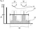
- Fig. 5 shows schematically the echo signals 20 received from a test object 10 over a time t.
- a single echo signal 20 is depicted as a bar having an amplitude A, and the incident ultrasonic pulse 5 with its amplitude A is diagrammed as a reference.
- This also shows the amplitude characteristic 22 as the envelope around the echo signals 20 after the step of evaluation and amplification of their amplitudes A within the defect expectation interval of time 24.
- a definite jump behavior of the echo signals 20 is shown twice.
- the gain factor 32 is varied for the evaluation. The variation in the gain factor 32 is depicted schematically.
- gain factor 32 within the respective sections 30, before and after the echo signals 20, shows the jump behavior as higher.
Landscapes
- Physics & Mathematics (AREA)
- Health & Medical Sciences (AREA)
- Life Sciences & Earth Sciences (AREA)
- Chemical & Material Sciences (AREA)
- Analytical Chemistry (AREA)
- Biochemistry (AREA)
- General Health & Medical Sciences (AREA)
- General Physics & Mathematics (AREA)
- Immunology (AREA)
- Pathology (AREA)
- Acoustics & Sound (AREA)
- Engineering & Computer Science (AREA)
- Signal Processing (AREA)
- Investigating Or Analyzing Materials By The Use Of Ultrasonic Waves (AREA)
Description
- The testing speed of ultrasonic test objects with an oblique angle of sound incidence in pulse-echo technology is linked to the sound field expansion across the direction of sound propagation of the ultrasonic field emitted by the ultrasonic transducer. Thus, in ultrasonic testing of thin-walled pipes, in which the pipe is "monitored" in the axial direction for suspicious reflections due to flaws in the pipe caused by multiple reflections on the walls of the pipe due to translational and/or rotational relative movements, for example, due a relative spiral movement, between the ultrasonic transducer and the pipe (= test object). The "lower" it is possible to identify defect echoes in the material of the test object or in thin-walled test objects in the case of oblique incidence of sound, despite acoustic damping, the greater the distance away from the point of sound incidence, the faster the complete detection of the test object can be.
-
WO 2004/005913 A1 discloses coupling an ultrasonic testing head to a spot weld.US 5 431 054 A1 discloses an ultrasonic flaw detection device with a transmitting transducer and a plurality of received transducers. - Due to the use of acoustic transducers having a greater sound-emitting (acoustically active) area, there is the possibility of mechanically enlarging the sound field expansion. However, this procedure has the disadvantage that the device becomes expensive and also that the requirements of acoustic coupling between the test object and the ultrasonic transducer become higher. However, a greater sound field expansion permits more rapid testing of a workpiece due to possible cost savings.
- There is therefore a demand for a method for ultrasonic testing according to the pulse-echo method, in which detection of defects is improved and in particular in which complete detection of the test object can be carried out more rapidly. This object is achieved by the method according to
Claim 1. Advantageous embodiments are the subject matter of the dependent claims. An equally advantageous device is the subject matter of the other independent claim, the device claim. - It should be pointed out that the features and steps of the method, which are mentioned individually in the claims, may be combined with one another in any technically logical manner and demonstrate additional embodiments of the invention. The description additionally characterizes and specifies the invention in conjunction with the figures in particular.
- The method according to the invention for ultrasonic testing according to the pulse-echo method has a step of oblique incidence of an ultrasonic pulse into a test object via a sound incidence surface by using an ultrasonic transducer. "Oblique" in the sense of the invention means that the main direction of propagation of the sound emitted from the ultrasonic transducer forms a non-right angle with the sound incidence surface, and thus the sound has a propagation component in the test object that is perpendicular to the plumb line to the input surface. The angle of incidence set in the step of oblique sound incidence is selected so that the main direction of propagation of the ultrasonic pulse assumes an angle to the sound incidence surface in the range of 40° to 50°, for example, approximately or exactly 45.0°, immediately after passing through the input surface.
- In addition to conventional test heads having round, rectangular or square ultrasonic transducers in various model sizes, for example, phased array test heads may preferably also be used.
- Furthermore, according to the invention, an evaluation of the amplitude characteristic of the echo signal over time in a predefined defect expectation interval of time is provided. The step of evaluation comprises, for example, comparison of the amplitude with a predefined threshold value to detect a defect in the test object, for example, when the threshold value is exceeded. The step of evaluation comprises according to the invention amplification, for example, electronic amplification in at least one section of the amplitude characteristic of the echo signal in the defect expectation interval of time. Amplification in the sense of the invention means, for example, amplifying the echo signal by a fixed gain factor in the respective section. Additionally, a decline in the threshold value occurs in the section of the amplitude characteristic of the echo signal. According to the invention, this amplification of the amplitude echo is to be equated with the reduction in the threshold value over time for defect detection and is thus also covered by the idea according to the invention.
- In comparison with known methods, the probability of detection of defects can be improved by the method according to the invention in the space of the test object through which the ultrasonic field passes, in particular a larger volume and/or a larger surface area being detectable per echo emission at the same ultrasonic emission power because the defect expectation interval of time can be increased in particular.
- According to a preferred embodiment of the method, the gain factor is varied in one section. Especially preferably the gain factor is varied in one section, in which a received echo signal has a pronounced jump behavior. The gain factor for the amplitudes of the received echo signals is increased immediately before and after the echo signal having the pronounced jump behavior.
- According to another embodiment of the method, the gain factor in the at least one section of the amplitude characteristic of the echo signal in the defect expectation interval of time increases steadily over time or decreases steadily over time, preferably increasing steadily over time. In particular the echo signal is subject to a damping over time, which can be attributed to a prolonged transit time, for example, due to reflections of an ultrasonic pulse in the test object. In general terms, it can be stated that the longer an ultrasonic pulse is underway in a test object and the more often it is reflected, the greater is the damping, wherein the term "longer" in the sense of the invention is to be understood as longer in time and also as longer in space. If an ultrasonic pulse is underway in a test object for a longer period of time, then it usually also travels a greater distance in the test object. Consequently, the received echo signal becomes progressively weaker within a defect expectation interval of time. A decline in the amplitude characteristic of the echo signal over time, the decline being induced in this way, can be compensated by an increase in the gain factor in the defect expectation interval of time.
- In particular in one embodiment of the method, the drop in amplitude, which is attributed to the damping due to the material and the geometry of the test object, is compensated. This is the case in particular when the echoes to be compared originate from a sound field at a comparatively great distance, which is formed due to multiple reflections and is therefore diffuse. For example, this occurs with a thin-walled pipe or sheet metal after a plurality of reflections on the wall (jumps) or when the ultrasonic receiver has large dimensions relative to the thickness of the material.
- Amplitudes of echoes from a diffuse sound field at a comparatively great distance may surprisingly also be used for defect analysis through the procedure according to the invention. In such an embodiment, the section of the amplification of the amplitude characteristic preferably located at the back end, chronologically, of the defect expectation interval of time. Due to this amplification and reduction in the threshold value, the sensitivity is increased, so that with a longer transit time of the echo signal, the amplitude damping can be counteracted and thus echoes that have run for a longer period of time in the test object can be used for the defect analysis.
- In another embodiment, the decline in amplitude, which is caused by a power loss at the side in the sound emission cone of the ultrasonic transducer, is compensated. Thus even defects which lie in the region of the decline in the sound emission cone at the side and whose amplitude drop is caused by this drop in the sound emission cone at the side can also be detected as flaws.
- In another embodiment, multiple sections of the amplitude characteristic of the echo signal are provided in the defect expectation interval of time, wherein the sections in the time characteristic of the gain factor are different. For example, in an early first section of the defect expectation interval of time, the decline in amplitude, which is caused by the power loss of the sound emission cone for early returning echoes, is compensated in an early first section of the defect expectation interval of time, and in a late second section of the defect expectation interval of time, the damping of echoes from the diffuse sound field at a great distance is compensated, so that the amplitudes of these echoes are amplified at least, so that they exceed the threshold value. The method is preferably designed, so that the gain factor increases steadily over the entire amplitude characteristic of the echo signal in the defect expectation interval of time.
- The test object is preferably a body having parallel walls, wherein one wall comprises the sound incidence surface, for example, the body is a sheet metal or a pipe. The method according to the invention is suitable for detecting both transverse defects as well as longitudinal defects on the walls. The method is suitable in particular for detection of transverse defects in thin-walled pipes, i.e., defects whose extent is essentially across the longitudinal extent of the pipe. The test object is preferably at a distance from the walls (= wall thickness) in the range of 0.5 mm to 10.0 mm, especially preferably in the range of 1.0 mm to 8.0 mm, most preferably in the range of 1.5 mm to 4.0 mm.
- The ultrasonic transducer preferably has a maximum outside dimension of its sound-emitting surface, which is in the range of greater than 10.0 mm, preferably greater than or equal to 12.0 mm, such as 18.0 mm or 24.0 mm.
- In a preferred embodiment, the duration of the defect expectation interval of time is selected so that multiple reflections in the test object are detected by the time characteristic of the echo signal in the defect expectation interval of time. Even more preferably, the defect expectation interval of time is selected so that multiple reflections on the walls of the test object (internal reflections) are detected by the time characteristic of the echo signal.
- A method according to any one of the preceding claims, having multiple sound incidence steps following one another in time and multiple intermediate or simultaneous steps of relative movement to achieve the most thorough possible sound bombardment of the test object. For example, the test object is rotated about one axis in the steps of the relative movement, and the ultrasonic transducer executes a translational movement along the sound incidence surface of the test objects, thus resulting in a spiral-shaped relative movement.
- The invention also relates to an arrangement for ultrasonic testing according to the pulse-echo method, which has an ultrasonic transducer configured for oblique sound incidence of an ultrasonic pulse over a sound incidence surface into a test object and for receiving the echo signal from the test object and an evaluation unit for evaluation of the amplitude characteristic of the echo signal over time in a predefined defect expectation interval of time and for comparison of the amplitude with a predefined threshold value. The evaluation unit is also designed according to the invention to amplify the amplitude characteristic of the echo signal in at least one section of the defect expectation interval of time and to lower the threshold. The change may be continuous or abrupt. The ultrasonic transducer is configured to emit an ultrasonic pulse such that the main direction of propagation of the ultrasonic pulse in the test object forms an angle with the sound incidence surface, this angle being in a range of 40° to 50°, for example, at approximately or exactly 45.0°.
- The arrangement preferably comprises a body having parallel walls as the test object, wherein one wall comprises the sound incidence surface. The body is preferably a pipe or a sheet metal.
- Essential features of one embodiment of the invention, in particular for testing thin-walled pipes, can be summarized as follows:
The testing speed in transverse defect testing depends on the material to be tested due to the effective sound field expansion, among other things. The electronic increase in the sound field expansion and thus the increase in testing speed are important aspects of the invention. - The amplitudes of defect signals depend on the transit times and/or the reflections, multiple reflections and/or discontinuities in the wall. The effective widths of the sound field resulting from the decline in sensitivity (based on -x dB) determine two important factors, the testing speed and the reproducibility. This is true in particular of transverse defect testing in pipes.
- Based on the ultrasonic transducer size and the thickness of the pipe wall to be tested, there is no pronounced jump behavior for the defect indication of the inside wall and the outside wall preferentially with thin-walled pipes, i.e., the defect indication is reduced continuously with the distance from the ultrasonic test head. This can be compensated by lengthening the defect expectation interval of time accordingly and a programmable sensitivity equalization/an increase in gain is carried out over the length/transit time of the evaluation aperture (DAC).
- If the signal-to-noise ratio is high enough, this equalization may take place for any length of time. Due to the sensitivity correction as a function of the path traveled, the evaluation is possible not only in the first jump but also in subsequent jumps. This results in a significant improvement in the effective width of the sound field and thus also an increase in the testing speed.
- With reference to the figures, additional features of the invention will be explained and illustrated below in a manner to be understood without restriction. These drawings show schematically:
- Fig. 1:
- a diagram of the oblique sound incidence of an ultrasonic pulse into a test object and multiple reflections within the test object,
- Fig. 2:
- a diagram of a rotational and translational relative movement between an ultrasonic transducer and a test object,
- Fig. 2a
- a projection of a surface tested in multiple rotations of the test object,
- Fig. 3:
- a diagram of the amplitudes of the received echo signals in an interval of time without an evaluation step,
- Fig. 4:
- a diagram of the amplitudes of the received echo signals in an interval of time with a gain step,
- Fig. 5
- a diagram of the amplitudes of the received echo signals in an interval of time with some definite jump behavior of the echo signals.
- In the different figures, parts that are equivalent with regard to their function are always labeled with the same reference numerals, so that they are usually described only once.
- It should be emphasized here again that the figures are purely schematic diagrams, which do not claim to be drawn true to scale.
-
Fig. 1 shows schematically how anultrasonic pulse 5 has oblique incidence into atest object 10 over asound incidence surface 7 by using anultrasonic transducer 6. The sound incidence angle, which is set within theultrasonic transducer 6, is selected so that, immediately after passage through thesound incidence surface 7, the main direction of propagation of theultrasonic pulse 5 forms an angle α of approximately 45° to the sound incidence surface. In the exemplary embodiment shown here, it is atest object 10 having parallel walls 12, for example, a pipe or sheet metal. One of the walls 12 is the outside wall 121 of the test object and the other wall 12 is the inside wall 122 of the test object. The outside wall 121 comprises thesound incidence surface 7 of theultrasonic pulse 5.Reflections 14 of theultrasonic pulse 5 on the walls 12 of thetest object 10 are shown, wherein theultrasonic pulse 5 is reflected several times on the walls 12 within thetest object 10. -
Fig. 2 shows schematically a diagram of a relative rotational movement and a relative translational movement between anultrasonic transducer 6 and atest object 10. Thetest object 10 is a pipe, which forms an outside wall 121 and an inside wall 122, which are parallel to one another. The pipe can be rotated about an axis x-x, which forms the central axis of the pipe at the same time. During an ultrasonic test, theultrasonic transducer 6 is arranged on the outside wall 121 of thetest object 10, which at the same time forms thesound incidence surface 7 by means of which theultrasonic pulse 5 is input into thetest object 10. The sound incidence of theultrasonic pulses 5 takes place in a plurality of sound incidence steps following one another chronologically. Intermediately or simultaneously with the sound incidence, theultrasonic transducer 6 is moved along thesound incidence surface 7 in the direction of the axis x-x and thetest object 10 is rotated about the axis x-x. This yields a relative spiral movement between theultrasonic transducer 6 and thetest object 10.Figure 2a shows schematically the projections of the surfaces tested per revolution of thetest object 10. -
Fig. 3 shows schematically the echo signals 20 received from atest object 10 over time t. Anecho signal 20 is depicted as a bar having an amplitude A. As a reference, theultrasonic pulse 5 incidence is represented schematically with the amplitude A. In addition, the essential amplitude characteristic 22 is diagrammed as the envelope around the echo signals 20. The amplitude A of the echo signals 20 is compared with athreshold value 26 within a defect expectation interval oftime 24. If thisthreshold value 26 is exceeded, adefect 28 in thetest object 10 is detected. In the example shown here, the amplitude A of the echo signals 20 declines continuously over the time t, and this decline is to be attributed to damping due to the material and the geometry of thetest object 10, for example. It may happen thatdefects 28 are not detected because the amplitudes A of the respective echo signals 20 are below thethreshold value 26 because of this damping. -
Fig. 4 shows schematically the echo signals 20 received from atest object 10 over time t. As is already known fromFig. 3 , asingle echo signal 20 is depicted as a bar having the amplitude A. The amplitudes A of the echo signals 20 are compared with thethreshold value 26 within the defect expectation interval oftime 24, wherein the amplitudes A of the echo signals 20 are amplified in at least onesection 30 of the defect expectation interval oftime 24. The curve of thegain factor 32 is also shown. Thegain factor 32 increases within thesection 30 and over the entiredefect expectation interval 24. Due to the step of amplification of the echo signals 20, thedefect 28 is now also identified, its amplitudes A without this step, as shown inFig. 1 , being below thethreshold value 26. Theamplitude characteristic 22 is depicted as an envelope around the echo signals 20, as is found after the step of evaluation and amplification of the amplitudes A. -
Fig. 5 shows schematically the echo signals 20 received from atest object 10 over a time t. Asingle echo signal 20 is depicted as a bar having an amplitude A, and the incidentultrasonic pulse 5 with its amplitude A is diagrammed as a reference. This also shows the amplitude characteristic 22 as the envelope around the echo signals 20 after the step of evaluation and amplification of their amplitudes A within the defect expectation interval oftime 24. Within the defect expectation interval oftime 24, a definite jump behavior of the echo signals 20 is shown twice. Within thesections 30 in which this jump behavior occurs, thegain factor 32 is varied for the evaluation. The variation in thegain factor 32 is depicted schematically. Thus, gainfactor 32, within therespective sections 30, before and after the echo signals 20, shows the jump behavior as higher.
Claims (12)
- A method for ultrasonic testing according to the pulse-echo method, the method comprising a step of oblique sound incidence of an ultrasonic pulse (5) via an input surface (7) into a test object (10) by using an ultrasonic transducer (6) and a step of receiving the echo signal (20) from the test object (10) with the ultrasonic transducer (6) and evaluating the amplitude (A) of the echo signal (20) over time in a predefined defect expectation interval of time (24) for comparison of the amplitude (A) with a predefined threshold value (26), wherein the step of evaluation includes amplification of the amplitude (A) with a gain factor (32) and a reduction in the threshold value (26) in at least one section (30) of the echo signal (20) in the defect expectation interval of time (24), wherein the sound incidence angle set in the step of oblique sound incidence is selected so that the main direction of propagation of the ultrasonic pulse (5) forms an angle (α) with the sound incidence surface (7) immediately after the ultrasonic pulse passes through the sound incidence surface (7), this angle being in the range of 40° to 50°, for example, at approximately or exactly 45.0°.
- The method according to Claim 1, wherein the gain factor varies within section (30).
- The method according to any one of the preceding claims, wherein the section (30) is situated on the back end chronologically of the defect expectation interval of time (24).
- The method according to any one of the preceding claims, wherein the gain factor (32) in the section (30) of the amplitude characteristic (22) of the echo signal (20) in the defect expectation interval of time (24) increases steadily with time or decreases steadily with time, preferably increasing steadily with time.
- The method according to any one of the preceding claims, having a plurality of sections (30) in the defect expectation interval of time (24), wherein the sections (30) differ in the characteristic of the gain factor (32) over time and/or in the threshold value variation (26).
- The method according to the preceding claim, wherein the gain factor (32) increases steadily over the entire amplitude characteristic (22) of the echo signal (20) in the defect expectation interval of time (24).
- The method according to any one of the preceding claims, wherein the test object (10) is a body having walls (12) parallel to one another, and a wall (12) comprises the sound incidence surface (7), for example, the body being a pipe or sheet metal.
- The method according to the preceding claim, wherein the test object (10) has a distance of the walls (12) (= wall thickness) in the range of 0.5 mm to 10.0 mm, preferably in the range of 1.0 to 8.0 mm, most preferably in the range of 1.5 mm to 4.0 mm.
- The method according to any one of the preceding claims, wherein the duration of the defection expectation interval of time (24) is selected, so that multiple reflections in the test object (10) are covered by the time characteristic of the echo signal (20) in the defect expectation interval of time (24); multiple reflections of the walls (12) of the test object (10) are preferably covered by the time characteristic of the echo signal (20) in the defect expectation interval of time (24).
- The method according to any one of the preceding claims, having a plurality of sound incidence steps following one another in time and a plurality of intermediate or simultaneous steps of relative movement, for example, the relative rotational and/or translational movement, between the ultrasonic transducer (6) emitting the sound and the test object (10), to achieve a complete sound bombardment of the test object (10), if possible.
- The method according to any one of the preceding claims, wherein the ultrasonic transducer (6) has a maximum outside dimension of its sound-emitting surface in the range of greater than 10.0 mm, preferably greater than or equal to 12.0 mm, such as 18.0 mm or 24.0 mm.
- An arrangement for ultrasonic testing according to the pulse-echo method, the arrangement having an ultrasonic transducer (6) configured for oblique sound incidence of an ultrasonic pulse (5) over a sound incidence surface (7) into a test object (10), and for receiving the echo signal (20) from the test object (10), and an evaluation unit for evaluating the amplitude (A) of the echo signal (20) over time in a predefined defect expectation interval of time (24) and for comparison of the amplitude (A) with a predefined threshold value (26), wherein the evaluation unit is also designed to amplify the amplitude characteristic (22) of the echo signal (20) and lower the threshold value (26) in at least one section (30) of the defect expectation interval of time (24), wherein the ultrasonic transducer (6) is configured to emit an ultrasonic pulse (5) such that a main direction of propagation of the ultrasonic pulse (5) in the test object forms an angle (α) with the sound incidence surface (7), this angle being in the range of 40° to 50°, for example, at approximately or exactly 45.0°.
Applications Claiming Priority (3)
| Application Number | Priority Date | Filing Date | Title |
|---|---|---|---|
| DE102014103165 | 2014-03-10 | ||
| DE102014109793.9A DE102014109793A1 (en) | 2014-03-10 | 2014-07-11 | Ultrasonic pulse-echo error test with high test speed, especially for thin-walled pipes |
| PCT/EP2015/054982 WO2015135950A1 (en) | 2014-03-10 | 2015-03-10 | Ultrasonic-pulse-echo flaw inspection at a high testing speed on thin-walled pipes in particular |
Publications (2)
| Publication Number | Publication Date |
|---|---|
| EP3117207A1 EP3117207A1 (en) | 2017-01-18 |
| EP3117207B1 true EP3117207B1 (en) | 2023-11-22 |
Family
ID=53883875
Family Applications (1)
| Application Number | Title | Priority Date | Filing Date |
|---|---|---|---|
| EP15708553.1A Active EP3117207B1 (en) | 2014-03-10 | 2015-03-10 | Ultrasonic-pulse-echo flaw inspection at a high testing speed on thin-walled pipes in particular |
Country Status (4)
| Country | Link |
|---|---|
| US (2) | US10241084B2 (en) |
| EP (1) | EP3117207B1 (en) |
| DE (1) | DE102014109793A1 (en) |
| WO (1) | WO2015135950A1 (en) |
Families Citing this family (3)
| Publication number | Priority date | Publication date | Assignee | Title |
|---|---|---|---|---|
| DE102014109793A1 (en) * | 2014-03-10 | 2015-09-10 | Ge Sensing & Inspection Technologies Gmbh | Ultrasonic pulse-echo error test with high test speed, especially for thin-walled pipes |
| KR102690264B1 (en) * | 2016-10-31 | 2024-07-30 | 엘지디스플레이 주식회사 | Organic light emitting display device |
| US10620162B2 (en) * | 2017-05-10 | 2020-04-14 | Baker Hughes, A Ge Company, Llc | Ultrasonic inspection methods and systems |
Citations (1)
| Publication number | Priority date | Publication date | Assignee | Title |
|---|---|---|---|---|
| US5431054A (en) * | 1994-04-07 | 1995-07-11 | Reeves; R. Dale | Ultrasonic flaw detection device |
Family Cites Families (22)
| Publication number | Priority date | Publication date | Assignee | Title |
|---|---|---|---|---|
| US3646805A (en) * | 1969-10-03 | 1972-03-07 | Amf Inc | Ultrasonic flaw detection circuit |
| DE1960458C3 (en) | 1969-12-02 | 1979-12-13 | Krautkraemer, Gmbh, 5000 Koeln | Procedure for setting the depth compensation on an ultrasonic pulse-echo device for uniform, depth-independent error sensitivity |
| US3895685A (en) * | 1971-04-19 | 1975-07-22 | Combustion Eng | Method and apparatus for ultrasonic inspection of weldments |
| DE2422439C2 (en) * | 1974-05-09 | 1983-12-08 | Krautkrämer GmbH, 5000 Köln | Method for adjusting the flaw aperture in an ultrasonic testing process |
| GB1543311A (en) | 1975-05-14 | 1979-04-04 | British Steel Corp | Ultrasonic inspection of articles |
| DE3307224C1 (en) * | 1983-03-02 | 1984-07-19 | Krautkrämer GmbH, 5000 Köln | Ultrasonic tester for non-destructive material testing with a controllable receiver amplifier |
| DE3822699A1 (en) | 1988-07-05 | 1990-01-11 | Krautkraemer Gmbh | METHOD AND DEVICE FOR MEASURING RUNTIME BY MEANS OF ULTRASOUND IN LIQUID OR SOLID MATERIALS BY THE IMPULSE REFLECTION METHOD |
| US5349860A (en) * | 1989-11-28 | 1994-09-27 | Nkk Corporation | Apparatus for measuring the thickness of clad material |
| US5497662A (en) * | 1993-09-07 | 1996-03-12 | General Electric Company | Method and apparatus for measuring and controlling refracted angle of ultrasonic waves |
| US5454045A (en) * | 1994-04-15 | 1995-09-26 | Battelle Memorial Institute | Apparatus and method for identification and recognition of an item with ultrasonic patterns from item subsurface micro-features |
| US5554808A (en) * | 1995-04-03 | 1996-09-10 | General Electric Company | System and method for detecting ply wrinkling in a laminated composite |
| DE10230587B4 (en) | 2002-07-05 | 2012-04-12 | Ge Sensing & Inspection Technologies Gmbh | Method and apparatus for ultrasonic testing of spot welded joints, in particular of body panels |
| US6938488B2 (en) | 2002-08-21 | 2005-09-06 | Battelle Memorial Institute | Acoustic inspection device |
| US7472598B2 (en) * | 2002-12-19 | 2009-01-06 | Agfa Ndt Gmbh | Ultrasonic inspection apparatus and method for evaluating ultrasonic signals |
| US7299697B2 (en) * | 2005-03-31 | 2007-11-27 | General Electric Company | Method and system for inspecting objects using ultrasound scan data |
| EP2249152A3 (en) * | 2009-05-05 | 2012-09-26 | Olympus NDT | A method and system for distance gain sizing using phased array systems |
| AU2011336762B2 (en) * | 2010-11-29 | 2015-04-09 | Board Of Regents Of The University Of Nebraska | System and method for ultrasonically evaluating structural properties |
| WO2013142645A1 (en) * | 2012-03-21 | 2013-09-26 | Board Of Regents Of The University Of Nebraska | Systems and methods to determine and monitor changes in rail conditions |
| DE102012112120B4 (en) * | 2012-12-11 | 2025-07-03 | Baker Hughes Digital Solutions Gmbh | Method and device for near-surface non-destructive testing of a rotationally symmetrical workpiece with sectionally changing diameter using ultrasound |
| DE102012112121B4 (en) * | 2012-12-11 | 2023-02-09 | Baker Hughes Digital Solutions Gmbh | Method and device for non-destructive testing of a rotationally symmetrical workpiece which has sections of different diameters |
| GB201314481D0 (en) | 2013-08-13 | 2013-09-25 | Dolphitech As | Imaging apparatus |
| DE102014109793A1 (en) * | 2014-03-10 | 2015-09-10 | Ge Sensing & Inspection Technologies Gmbh | Ultrasonic pulse-echo error test with high test speed, especially for thin-walled pipes |
-
2014
- 2014-07-11 DE DE102014109793.9A patent/DE102014109793A1/en not_active Ceased
-
2015
- 2015-03-10 US US15/124,702 patent/US10241084B2/en active Active
- 2015-03-10 EP EP15708553.1A patent/EP3117207B1/en active Active
- 2015-03-10 WO PCT/EP2015/054982 patent/WO2015135950A1/en not_active Ceased
-
2019
- 2019-02-13 US US16/274,708 patent/US10488367B2/en active Active
Patent Citations (1)
| Publication number | Priority date | Publication date | Assignee | Title |
|---|---|---|---|---|
| US5431054A (en) * | 1994-04-07 | 1995-07-11 | Reeves; R. Dale | Ultrasonic flaw detection device |
Also Published As
| Publication number | Publication date |
|---|---|
| US20170016860A1 (en) | 2017-01-19 |
| US20190178846A1 (en) | 2019-06-13 |
| US10241084B2 (en) | 2019-03-26 |
| WO2015135950A1 (en) | 2015-09-17 |
| EP3117207A1 (en) | 2017-01-18 |
| DE102014109793A1 (en) | 2015-09-10 |
| US10488367B2 (en) | 2019-11-26 |
Similar Documents
| Publication | Publication Date | Title |
|---|---|---|
| JP5448092B2 (en) | Ultrasonic flaw detection method and apparatus for welds | |
| JP4910770B2 (en) | Tubular ultrasonic inspection apparatus and ultrasonic inspection method | |
| US7874212B2 (en) | Ultrasonic probe, ultrasonic flaw detection method, and ultrasonic flaw detection apparatus | |
| US5431054A (en) | Ultrasonic flaw detection device | |
| US10473624B2 (en) | Shear wave sensors for acoustic emission and hybrid guided wave testing | |
| US9927405B2 (en) | Processing signals acquired during guided wave testing | |
| US10488367B2 (en) | Ultrasonic-pulse-echo flaw inspection at a high testing speed on thin-walled pipes in particular | |
| CN110914682A (en) | Non-destructive inspection for tubular products having complex shapes | |
| CN113874721B (en) | A method and device for non-destructive testing of plate materials | |
| US20140305219A1 (en) | Conical ultrasonic probe | |
| JP2000352563A (en) | Ultrasonic flaw detector for cladding tube | |
| CN117705938A (en) | Phased array ultrasonic flaw detection method for special-shaped thick-wall pipe | |
| JP2015148602A (en) | ultrasonic flaw detection method | |
| US11913909B2 (en) | Device and method for determining the extent of defects by means of v through-transmission | |
| JP6953953B2 (en) | A method for evaluating the soundness of oblique ultrasonic flaw detection, and a method for oblique ultrasonic flaw detection using this method. | |
| Loveday | Feasibility of detecting cracks in rail track at long range using guided wave ultrasound | |
| JP2006003150A (en) | Oblique probe and ultrasonic flaw detector | |
| US8375795B2 (en) | Non-destructive inspection of high-pressure lines | |
| WO2018135242A1 (en) | Inspection method | |
| US20240210358A1 (en) | Method and Device for Checking the Wall of a Pipeline for Flaws | |
| RU2377555C1 (en) | Method for ultrasonic inspection of objects | |
| CA3097601C (en) | Device and method for determining the extent of defects by means of v transmission | |
| JPH08233786A (en) | Metal body surface layer inspection apparatus and surface layer inspection method by ultrasonic wave propagation time | |
| JP2007147423A (en) | Internal defect detection method and internal defect detection apparatus for rolled material | |
| CN120668791A (en) | Ultrasonic detection device and method for large-caliber thin-wall titanium alloy pipe |
Legal Events
| Date | Code | Title | Description |
|---|---|---|---|
| STAA | Information on the status of an ep patent application or granted ep patent |
Free format text: STATUS: THE INTERNATIONAL PUBLICATION HAS BEEN MADE |
|
| PUAI | Public reference made under article 153(3) epc to a published international application that has entered the european phase |
Free format text: ORIGINAL CODE: 0009012 |
|
| STAA | Information on the status of an ep patent application or granted ep patent |
Free format text: STATUS: REQUEST FOR EXAMINATION WAS MADE |
|
| 17P | Request for examination filed |
Effective date: 20161010 |
|
| AK | Designated contracting states |
Kind code of ref document: A1 Designated state(s): AL AT BE BG CH CY CZ DE DK EE ES FI FR GB GR HR HU IE IS IT LI LT LU LV MC MK MT NL NO PL PT RO RS SE SI SK SM TR |
|
| AX | Request for extension of the european patent |
Extension state: BA ME |
|
| DAV | Request for validation of the european patent (deleted) | ||
| DAX | Request for extension of the european patent (deleted) | ||
| STAA | Information on the status of an ep patent application or granted ep patent |
Free format text: STATUS: EXAMINATION IS IN PROGRESS |
|
| 17Q | First examination report despatched |
Effective date: 20191104 |
|
| P01 | Opt-out of the competence of the unified patent court (upc) registered |
Effective date: 20230526 |
|
| GRAP | Despatch of communication of intention to grant a patent |
Free format text: ORIGINAL CODE: EPIDOSNIGR1 |
|
| STAA | Information on the status of an ep patent application or granted ep patent |
Free format text: STATUS: GRANT OF PATENT IS INTENDED |
|
| INTG | Intention to grant announced |
Effective date: 20230710 |
|
| GRAS | Grant fee paid |
Free format text: ORIGINAL CODE: EPIDOSNIGR3 |
|
| GRAA | (expected) grant |
Free format text: ORIGINAL CODE: 0009210 |
|
| STAA | Information on the status of an ep patent application or granted ep patent |
Free format text: STATUS: THE PATENT HAS BEEN GRANTED |
|
| AK | Designated contracting states |
Kind code of ref document: B1 Designated state(s): AL AT BE BG CH CY CZ DE DK EE ES FI FR GB GR HR HU IE IS IT LI LT LU LV MC MK MT NL NO PL PT RO RS SE SI SK SM TR |
|
| REG | Reference to a national code |
Ref country code: GB Ref legal event code: FG4D |
|
| REG | Reference to a national code |
Ref country code: CH Ref legal event code: EP Ref country code: DE Ref legal event code: R096 Ref document number: 602015086621 Country of ref document: DE |
|
| REG | Reference to a national code |
Ref country code: IE Ref legal event code: FG4D |
|
| REG | Reference to a national code |
Ref country code: LT Ref legal event code: MG9D |
|
| REG | Reference to a national code |
Ref country code: NL Ref legal event code: MP Effective date: 20231122 |
|
| PG25 | Lapsed in a contracting state [announced via postgrant information from national office to epo] |
Ref country code: GR Free format text: LAPSE BECAUSE OF FAILURE TO SUBMIT A TRANSLATION OF THE DESCRIPTION OR TO PAY THE FEE WITHIN THE PRESCRIBED TIME-LIMIT Effective date: 20240223 |
|
| PG25 | Lapsed in a contracting state [announced via postgrant information from national office to epo] |
Ref country code: IS Free format text: LAPSE BECAUSE OF FAILURE TO SUBMIT A TRANSLATION OF THE DESCRIPTION OR TO PAY THE FEE WITHIN THE PRESCRIBED TIME-LIMIT Effective date: 20240322 |
|
| RAP4 | Party data changed (patent owner data changed or rights of a patent transferred) |
Owner name: BAKER HUGHES DIGITAL SOLUTIONS GMBH |
|
| PG25 | Lapsed in a contracting state [announced via postgrant information from national office to epo] |
Ref country code: LT Free format text: LAPSE BECAUSE OF FAILURE TO SUBMIT A TRANSLATION OF THE DESCRIPTION OR TO PAY THE FEE WITHIN THE PRESCRIBED TIME-LIMIT Effective date: 20231122 |
|
| REG | Reference to a national code |
Ref country code: AT Ref legal event code: MK05 Ref document number: 1634277 Country of ref document: AT Kind code of ref document: T Effective date: 20231122 |
|
| PG25 | Lapsed in a contracting state [announced via postgrant information from national office to epo] |
Ref country code: NL Free format text: LAPSE BECAUSE OF FAILURE TO SUBMIT A TRANSLATION OF THE DESCRIPTION OR TO PAY THE FEE WITHIN THE PRESCRIBED TIME-LIMIT Effective date: 20231122 |
|
| PG25 | Lapsed in a contracting state [announced via postgrant information from national office to epo] |
Ref country code: AT Free format text: LAPSE BECAUSE OF FAILURE TO SUBMIT A TRANSLATION OF THE DESCRIPTION OR TO PAY THE FEE WITHIN THE PRESCRIBED TIME-LIMIT Effective date: 20231122 |
|
| PG25 | Lapsed in a contracting state [announced via postgrant information from national office to epo] |
Ref country code: ES Free format text: LAPSE BECAUSE OF FAILURE TO SUBMIT A TRANSLATION OF THE DESCRIPTION OR TO PAY THE FEE WITHIN THE PRESCRIBED TIME-LIMIT Effective date: 20231122 |
|
| PG25 | Lapsed in a contracting state [announced via postgrant information from national office to epo] |
Ref country code: NL Free format text: LAPSE BECAUSE OF FAILURE TO SUBMIT A TRANSLATION OF THE DESCRIPTION OR TO PAY THE FEE WITHIN THE PRESCRIBED TIME-LIMIT Effective date: 20231122 Ref country code: LT Free format text: LAPSE BECAUSE OF FAILURE TO SUBMIT A TRANSLATION OF THE DESCRIPTION OR TO PAY THE FEE WITHIN THE PRESCRIBED TIME-LIMIT Effective date: 20231122 Ref country code: IS Free format text: LAPSE BECAUSE OF FAILURE TO SUBMIT A TRANSLATION OF THE DESCRIPTION OR TO PAY THE FEE WITHIN THE PRESCRIBED TIME-LIMIT Effective date: 20240322 Ref country code: GR Free format text: LAPSE BECAUSE OF FAILURE TO SUBMIT A TRANSLATION OF THE DESCRIPTION OR TO PAY THE FEE WITHIN THE PRESCRIBED TIME-LIMIT Effective date: 20240223 Ref country code: ES Free format text: LAPSE BECAUSE OF FAILURE TO SUBMIT A TRANSLATION OF THE DESCRIPTION OR TO PAY THE FEE WITHIN THE PRESCRIBED TIME-LIMIT Effective date: 20231122 Ref country code: BG Free format text: LAPSE BECAUSE OF FAILURE TO SUBMIT A TRANSLATION OF THE DESCRIPTION OR TO PAY THE FEE WITHIN THE PRESCRIBED TIME-LIMIT Effective date: 20240222 Ref country code: AT Free format text: LAPSE BECAUSE OF FAILURE TO SUBMIT A TRANSLATION OF THE DESCRIPTION OR TO PAY THE FEE WITHIN THE PRESCRIBED TIME-LIMIT Effective date: 20231122 Ref country code: PT Free format text: LAPSE BECAUSE OF FAILURE TO SUBMIT A TRANSLATION OF THE DESCRIPTION OR TO PAY THE FEE WITHIN THE PRESCRIBED TIME-LIMIT Effective date: 20240322 |
|
| PGFP | Annual fee paid to national office [announced via postgrant information from national office to epo] |
Ref country code: DE Payment date: 20240220 Year of fee payment: 10 |
|
| PG25 | Lapsed in a contracting state [announced via postgrant information from national office to epo] |
Ref country code: SE Free format text: LAPSE BECAUSE OF FAILURE TO SUBMIT A TRANSLATION OF THE DESCRIPTION OR TO PAY THE FEE WITHIN THE PRESCRIBED TIME-LIMIT Effective date: 20231122 Ref country code: RS Free format text: LAPSE BECAUSE OF FAILURE TO SUBMIT A TRANSLATION OF THE DESCRIPTION OR TO PAY THE FEE WITHIN THE PRESCRIBED TIME-LIMIT Effective date: 20231122 Ref country code: PL Free format text: LAPSE BECAUSE OF FAILURE TO SUBMIT A TRANSLATION OF THE DESCRIPTION OR TO PAY THE FEE WITHIN THE PRESCRIBED TIME-LIMIT Effective date: 20231122 Ref country code: NO Free format text: LAPSE BECAUSE OF FAILURE TO SUBMIT A TRANSLATION OF THE DESCRIPTION OR TO PAY THE FEE WITHIN THE PRESCRIBED TIME-LIMIT Effective date: 20240222 Ref country code: LV Free format text: LAPSE BECAUSE OF FAILURE TO SUBMIT A TRANSLATION OF THE DESCRIPTION OR TO PAY THE FEE WITHIN THE PRESCRIBED TIME-LIMIT Effective date: 20231122 Ref country code: HR Free format text: LAPSE BECAUSE OF FAILURE TO SUBMIT A TRANSLATION OF THE DESCRIPTION OR TO PAY THE FEE WITHIN THE PRESCRIBED TIME-LIMIT Effective date: 20231122 |
|
| PG25 | Lapsed in a contracting state [announced via postgrant information from national office to epo] |
Ref country code: DK Free format text: LAPSE BECAUSE OF FAILURE TO SUBMIT A TRANSLATION OF THE DESCRIPTION OR TO PAY THE FEE WITHIN THE PRESCRIBED TIME-LIMIT Effective date: 20231122 |
|
| PG25 | Lapsed in a contracting state [announced via postgrant information from national office to epo] |
Ref country code: CZ Free format text: LAPSE BECAUSE OF FAILURE TO SUBMIT A TRANSLATION OF THE DESCRIPTION OR TO PAY THE FEE WITHIN THE PRESCRIBED TIME-LIMIT Effective date: 20231122 |
|
| PG25 | Lapsed in a contracting state [announced via postgrant information from national office to epo] |
Ref country code: SK Free format text: LAPSE BECAUSE OF FAILURE TO SUBMIT A TRANSLATION OF THE DESCRIPTION OR TO PAY THE FEE WITHIN THE PRESCRIBED TIME-LIMIT Effective date: 20231122 |
|
| PG25 | Lapsed in a contracting state [announced via postgrant information from national office to epo] |
Ref country code: SM Free format text: LAPSE BECAUSE OF FAILURE TO SUBMIT A TRANSLATION OF THE DESCRIPTION OR TO PAY THE FEE WITHIN THE PRESCRIBED TIME-LIMIT Effective date: 20231122 Ref country code: SK Free format text: LAPSE BECAUSE OF FAILURE TO SUBMIT A TRANSLATION OF THE DESCRIPTION OR TO PAY THE FEE WITHIN THE PRESCRIBED TIME-LIMIT Effective date: 20231122 Ref country code: RO Free format text: LAPSE BECAUSE OF FAILURE TO SUBMIT A TRANSLATION OF THE DESCRIPTION OR TO PAY THE FEE WITHIN THE PRESCRIBED TIME-LIMIT Effective date: 20231122 Ref country code: IT Free format text: LAPSE BECAUSE OF FAILURE TO SUBMIT A TRANSLATION OF THE DESCRIPTION OR TO PAY THE FEE WITHIN THE PRESCRIBED TIME-LIMIT Effective date: 20231122 Ref country code: EE Free format text: LAPSE BECAUSE OF FAILURE TO SUBMIT A TRANSLATION OF THE DESCRIPTION OR TO PAY THE FEE WITHIN THE PRESCRIBED TIME-LIMIT Effective date: 20231122 Ref country code: DK Free format text: LAPSE BECAUSE OF FAILURE TO SUBMIT A TRANSLATION OF THE DESCRIPTION OR TO PAY THE FEE WITHIN THE PRESCRIBED TIME-LIMIT Effective date: 20231122 Ref country code: CZ Free format text: LAPSE BECAUSE OF FAILURE TO SUBMIT A TRANSLATION OF THE DESCRIPTION OR TO PAY THE FEE WITHIN THE PRESCRIBED TIME-LIMIT Effective date: 20231122 |
|
| REG | Reference to a national code |
Ref country code: DE Ref legal event code: R097 Ref document number: 602015086621 Country of ref document: DE |
|
| PLBE | No opposition filed within time limit |
Free format text: ORIGINAL CODE: 0009261 |
|
| STAA | Information on the status of an ep patent application or granted ep patent |
Free format text: STATUS: NO OPPOSITION FILED WITHIN TIME LIMIT |
|
| PG25 | Lapsed in a contracting state [announced via postgrant information from national office to epo] |
Ref country code: SI Free format text: LAPSE BECAUSE OF FAILURE TO SUBMIT A TRANSLATION OF THE DESCRIPTION OR TO PAY THE FEE WITHIN THE PRESCRIBED TIME-LIMIT Effective date: 20231122 |
|
| 26N | No opposition filed |
Effective date: 20240823 |
|
| PG25 | Lapsed in a contracting state [announced via postgrant information from national office to epo] |
Ref country code: SI Free format text: LAPSE BECAUSE OF FAILURE TO SUBMIT A TRANSLATION OF THE DESCRIPTION OR TO PAY THE FEE WITHIN THE PRESCRIBED TIME-LIMIT Effective date: 20231122 |
|
| REG | Reference to a national code |
Ref country code: CH Ref legal event code: PL |
|
| PG25 | Lapsed in a contracting state [announced via postgrant information from national office to epo] |
Ref country code: LU Free format text: LAPSE BECAUSE OF NON-PAYMENT OF DUE FEES Effective date: 20240310 |
|
| PG25 | Lapsed in a contracting state [announced via postgrant information from national office to epo] |
Ref country code: MC Free format text: LAPSE BECAUSE OF FAILURE TO SUBMIT A TRANSLATION OF THE DESCRIPTION OR TO PAY THE FEE WITHIN THE PRESCRIBED TIME-LIMIT Effective date: 20231122 |
|
| GBPC | Gb: european patent ceased through non-payment of renewal fee |
Effective date: 20240310 |
|
| PG25 | Lapsed in a contracting state [announced via postgrant information from national office to epo] |
Ref country code: MC Free format text: LAPSE BECAUSE OF FAILURE TO SUBMIT A TRANSLATION OF THE DESCRIPTION OR TO PAY THE FEE WITHIN THE PRESCRIBED TIME-LIMIT Effective date: 20231122 Ref country code: LU Free format text: LAPSE BECAUSE OF NON-PAYMENT OF DUE FEES Effective date: 20240310 |
|
| REG | Reference to a national code |
Ref country code: BE Ref legal event code: MM Effective date: 20240331 |
|
| PG25 | Lapsed in a contracting state [announced via postgrant information from national office to epo] |
Ref country code: BE Free format text: LAPSE BECAUSE OF NON-PAYMENT OF DUE FEES Effective date: 20240331 |
|
| PG25 | Lapsed in a contracting state [announced via postgrant information from national office to epo] |
Ref country code: GB Free format text: LAPSE BECAUSE OF NON-PAYMENT OF DUE FEES Effective date: 20240310 |
|
| PG25 | Lapsed in a contracting state [announced via postgrant information from national office to epo] |
Ref country code: FR Free format text: LAPSE BECAUSE OF NON-PAYMENT OF DUE FEES Effective date: 20240331 |
|
| PG25 | Lapsed in a contracting state [announced via postgrant information from national office to epo] |
Ref country code: IE Free format text: LAPSE BECAUSE OF NON-PAYMENT OF DUE FEES Effective date: 20240310 |
|
| PG25 | Lapsed in a contracting state [announced via postgrant information from national office to epo] |
Ref country code: IE Free format text: LAPSE BECAUSE OF NON-PAYMENT OF DUE FEES Effective date: 20240310 Ref country code: GB Free format text: LAPSE BECAUSE OF NON-PAYMENT OF DUE FEES Effective date: 20240310 Ref country code: FR Free format text: LAPSE BECAUSE OF NON-PAYMENT OF DUE FEES Effective date: 20240331 Ref country code: BE Free format text: LAPSE BECAUSE OF NON-PAYMENT OF DUE FEES Effective date: 20240331 Ref country code: CH Free format text: LAPSE BECAUSE OF NON-PAYMENT OF DUE FEES Effective date: 20240331 |
|
| PG25 | Lapsed in a contracting state [announced via postgrant information from national office to epo] |
Ref country code: CY Free format text: LAPSE BECAUSE OF FAILURE TO SUBMIT A TRANSLATION OF THE DESCRIPTION OR TO PAY THE FEE WITHIN THE PRESCRIBED TIME-LIMIT; INVALID AB INITIO Effective date: 20150310 |
|
| PG25 | Lapsed in a contracting state [announced via postgrant information from national office to epo] |
Ref country code: HU Free format text: LAPSE BECAUSE OF FAILURE TO SUBMIT A TRANSLATION OF THE DESCRIPTION OR TO PAY THE FEE WITHIN THE PRESCRIBED TIME-LIMIT; INVALID AB INITIO Effective date: 20150310 |
|
| REG | Reference to a national code |
Ref country code: DE Ref legal event code: R119 Ref document number: 602015086621 Country of ref document: DE |
|
| PG25 | Lapsed in a contracting state [announced via postgrant information from national office to epo] |
Ref country code: FI Free format text: LAPSE BECAUSE OF FAILURE TO SUBMIT A TRANSLATION OF THE DESCRIPTION OR TO PAY THE FEE WITHIN THE PRESCRIBED TIME-LIMIT Effective date: 20231122 |
|
| PG25 | Lapsed in a contracting state [announced via postgrant information from national office to epo] |
Ref country code: TR Free format text: LAPSE BECAUSE OF FAILURE TO SUBMIT A TRANSLATION OF THE DESCRIPTION OR TO PAY THE FEE WITHIN THE PRESCRIBED TIME-LIMIT Effective date: 20231122 |
|
| PG25 | Lapsed in a contracting state [announced via postgrant information from national office to epo] |
Ref country code: DE Free format text: LAPSE BECAUSE OF NON-PAYMENT OF DUE FEES Effective date: 20251001 |