EP3116404B1 - Medical diagnostic apparatus and operating method thereof - Google Patents
Medical diagnostic apparatus and operating method thereof Download PDFInfo
- Publication number
- EP3116404B1 EP3116404B1 EP15761364.7A EP15761364A EP3116404B1 EP 3116404 B1 EP3116404 B1 EP 3116404B1 EP 15761364 A EP15761364 A EP 15761364A EP 3116404 B1 EP3116404 B1 EP 3116404B1
- Authority
- EP
- European Patent Office
- Prior art keywords
- state
- diagnostic apparatus
- medical diagnostic
- history
- medical
- Prior art date
- Legal status (The legal status is an assumption and is not a legal conclusion. Google has not performed a legal analysis and makes no representation as to the accuracy of the status listed.)
- Active
Links
Images





Classifications
-
- A—HUMAN NECESSITIES
- A61—MEDICAL OR VETERINARY SCIENCE; HYGIENE
- A61B—DIAGNOSIS; SURGERY; IDENTIFICATION
- A61B8/00—Diagnosis using ultrasonic, sonic or infrasonic waves
- A61B8/46—Ultrasonic, sonic or infrasonic diagnostic devices with special arrangements for interfacing with the operator or the patient
- A61B8/461—Displaying means of special interest
- A61B8/463—Displaying means of special interest characterised by displaying multiple images or images and diagnostic data on one display
-
- A—HUMAN NECESSITIES
- A61—MEDICAL OR VETERINARY SCIENCE; HYGIENE
- A61B—DIAGNOSIS; SURGERY; IDENTIFICATION
- A61B8/00—Diagnosis using ultrasonic, sonic or infrasonic waves
- A61B8/46—Ultrasonic, sonic or infrasonic diagnostic devices with special arrangements for interfacing with the operator or the patient
- A61B8/461—Displaying means of special interest
- A61B8/465—Displaying means of special interest adapted to display user selection data, e.g. icons or menus
-
- A—HUMAN NECESSITIES
- A61—MEDICAL OR VETERINARY SCIENCE; HYGIENE
- A61B—DIAGNOSIS; SURGERY; IDENTIFICATION
- A61B8/00—Diagnosis using ultrasonic, sonic or infrasonic waves
- A61B8/46—Ultrasonic, sonic or infrasonic diagnostic devices with special arrangements for interfacing with the operator or the patient
- A61B8/467—Ultrasonic, sonic or infrasonic diagnostic devices with special arrangements for interfacing with the operator or the patient characterised by special input means
-
- A—HUMAN NECESSITIES
- A61—MEDICAL OR VETERINARY SCIENCE; HYGIENE
- A61B—DIAGNOSIS; SURGERY; IDENTIFICATION
- A61B2560/00—Constructional details of operational features of apparatus; Accessories for medical measuring apparatus
- A61B2560/04—Constructional details of apparatus
- A61B2560/0475—Special features of memory means, e.g. removable memory cards
-
- A—HUMAN NECESSITIES
- A61—MEDICAL OR VETERINARY SCIENCE; HYGIENE
- A61B—DIAGNOSIS; SURGERY; IDENTIFICATION
- A61B2560/00—Constructional details of operational features of apparatus; Accessories for medical measuring apparatus
- A61B2560/04—Constructional details of apparatus
- A61B2560/0487—Special user inputs or interfaces
-
- A—HUMAN NECESSITIES
- A61—MEDICAL OR VETERINARY SCIENCE; HYGIENE
- A61B—DIAGNOSIS; SURGERY; IDENTIFICATION
- A61B2576/00—Medical imaging apparatus involving image processing or analysis
-
- A—HUMAN NECESSITIES
- A61—MEDICAL OR VETERINARY SCIENCE; HYGIENE
- A61B—DIAGNOSIS; SURGERY; IDENTIFICATION
- A61B5/00—Measuring for diagnostic purposes; Identification of persons
- A61B5/74—Details of notification to user or communication with user or patient; User input means
- A61B5/7475—User input or interface means, e.g. keyboard, pointing device, joystick
-
- A—HUMAN NECESSITIES
- A61—MEDICAL OR VETERINARY SCIENCE; HYGIENE
- A61B—DIAGNOSIS; SURGERY; IDENTIFICATION
- A61B6/00—Apparatus or devices for radiation diagnosis; Apparatus or devices for radiation diagnosis combined with radiation therapy equipment
- A61B6/46—Arrangements for interfacing with the operator or the patient
- A61B6/461—Displaying means of special interest
- A61B6/465—Displaying means of special interest adapted to display user selection data, e.g. graphical user interface, icons or menus
-
- A—HUMAN NECESSITIES
- A61—MEDICAL OR VETERINARY SCIENCE; HYGIENE
- A61B—DIAGNOSIS; SURGERY; IDENTIFICATION
- A61B8/00—Diagnosis using ultrasonic, sonic or infrasonic waves
- A61B8/08—Clinical applications
- A61B8/0866—Clinical applications involving foetal diagnosis; pre-natal or peri-natal diagnosis of the baby
Definitions
- One or more embodiments of the present invention relate to a medical diagnostic apparatus and a method of operating the medical diagnostic apparatus, and more particularly, to a medical diagnostic apparatus having functions of storing history of an operating state of the medical diagnostic apparatus that is modified according to a user input and returning to a predetermined operating state included in the history, and a method of operating the medical diagnostic apparatus.
- a medical diagnostic apparatus displays a medical image so as to provide a user with information about diagnosis of a disease and information for treatment.
- the medical diagnostic apparatus may be an additional apparatus separated from an apparatus for obtaining a medical image or may include an apparatus for obtaining a medical image.
- An apparatus for obtaining a medical image irradiates a predetermined signal toward an object and obtains a medical image about a cross-section or hematocele of the object by using a signal reflected from the object or a signal that has transmitted through the object.
- an apparatus for obtaining a medical image may obtain an ultrasound image, an X-ray image, a computerized tomography (CT) image, a magnetic resonance (MR) image, or a positron emission tomography (PET) image.
- CT computerized tomography
- MR magnetic resonance
- PET positron emission tomography
- EP-2 1455 580 is acknowledged as prior art, as well as US-2011/137836 .
- EP 2 1455 580 is directed to ultrasound systems, and more particularly to a recovery function of parameters in an ultrasound system while US2011/137836 is directed to a sensor network system that includes a sensor node for measuring living organism information.
- US2011/137836 is directed to a sensor network system that includes a sensor node for measuring living organism information.
- it relates to a technology of obtaining an activity history of a monitored subject with the use of a sensor node worn by the monitored subject, and analyzing an activity pattern of the monitored subject from the activity history.
- One or more embodiments of the present invention include a medical diagnostic apparatus having functions of storing a history of an operating state of the medical diagnostic apparatus and returning to a previous state from among a plurality of operating states included in the history, and a method of operating the medical diagnostic apparatus.
- a method of operating a medical diagnostic apparatus that displays a medical image includes steps defined in the appended independent method claim.
- a medical diagnostic apparatus includes features defined in the appended independent apparatus claim.
- a non-transitory computer readable recording medium having embodied thereon a program for executing the method described above is included.
- Preferred embodiments may be defined in dependent claims, and/or be apparent from the following embodiment description.
- a term 'object' may be an animated object or an inanimated object, which is displayed via an image.
- the object may be a part of a human body and may include the liver, the heart, the womb, the brain, the breast, the abdominal region, or the like, a fetus, or a cross-section of a part of a human body.
- a "user” may be, without limitation, a medical expert including a doctor, a nurse, a medical laboratory technologist, a sonographer, a medical image expert, or the like.
- a medical diagnostic apparatus provides a medical image about an object and is used in diagnosis and treatment of a disease.
- a medical diagnostic apparatus may obtain image data about an object, generate a medical image based on the image data, and display the medical image on a screen.
- a user may operate a medical diagnostic apparatus such that the medical diagnostic apparatus transmits or receives a predetermined signal to or from an object in order to obtain image data, or sets various parameters needed to generate a medical image from image data, or modifies a displaying method of displaying the medical image on a screen.
- the medical diagnostic apparatus transmits or receives a predetermined signal to or from an object in order to obtain image data, or sets various parameters needed to generate a medical image from image data, or modifies a displaying method of displaying the medical image on a screen.
- the present invention has been designed to solve the problem of the conventional art.
- FIG. 1 is a block diagram illustrating a medical diagnostic apparatus 100 according to an embodiment of the present invention.
- the medical diagnostic apparatus 100 includes a display unit 110, a user input unit 120, a storage unit 130, and a controller 140.
- the display unit 110 displays a medical image based on an operating state of the medical diagnostic apparatus 100.
- the display unit 110 may further display a history of the medical diagnostic apparatus 100 stored in the storage unit 130.
- the display unit 110 may display not only a medical image generated by using the medical diagnostic apparatus 100 but also various information processed in the medical diagnostic apparatus 100 through a graphic user interface (GUI).
- GUI graphic user interface
- the user input unit 120 receives a user input.
- a user input may refer to data or a signal that is input to the medical diagnostic apparatus 100 by a user.
- a user input may refer to data or a signal through which an event, which is a motive of initiating or completing a predetermined operation, is generated.
- a user input may be received through, for example, a control panel, a keyboard, and a touch panel included in the medical diagnostic apparatus 100.
- the medical diagnostic apparatus 100 may output a new medical image that is obtained by rotating, moving or expanding or reducing a currently displayed medical image.
- the user input unit 120 refers to a unit through which a user inputs data or a signal for operating the medical diagnostic apparatus 100.
- the user input unit 120 according to the current embodiment of the present invention sequentially receives a plurality of user inputs.
- the user input unit 120 may further include a recovery input via which an operating state of the medical diagnostic apparatus is modified to a predetermined operating state included in the history.
- Examples of the user input unit 120 include, without limitation, a key pad, a dome switch, a mouse, a sensor, a knob button, a touch pad (capacitive overlay type, resistive overlay type, infrared beam type, integral strain gauge type, surface acoustic wave type, piezoelectric type or the like), a jog wheel, and a jog switch. Also, a touch pad which is in a layered structure with a display panel of the display unit 110 may be referred to as a touch screen.
- the user input unit 120 may include a sensor that receives a temperature input, a pressure input, or a sound input or the like.
- the storage unit 130 stores a history of a plurality of operating states of the medical diagnostic apparatus 100 respectively corresponding to user inputs.
- the storage unit 130 may store, from among a plurality of operating states, at least one operating state corresponding at least one user input selected by using the controller 140, as a history. Also, the storage unit 130 may store image data that is used to generate a medical image.
- the controller 140 controls the overall operation of the medical diagnostic apparatus 100, and controls the display unit 110, the user input unit 120, and the storage unit 130 such that a medical image is displayed based on an operating state of the medical diagnostic apparatus 100. Also, the controller 140 may include a processor (not shown) that generates a medical image based on image data. Image data that the controller 140 uses to generate a medical image may be obtained from the storage unit 130 or may be generated by using the controller 140 based on a signal received from an object in response to a signal that is transmitted to the object, or may be received from an external device or an external server.
- the controller 140 modifies an operating state of the medical diagnostic apparatus 100 based on user inputs. For example, the controller 140 may modify an operating state of the medical diagnostic apparatus from a first state to a second state based on a plurality of first user inputs that are sequentially received.
- the controller 140 may modify an operating state of the medical diagnostic apparatus by modifying a displaying method in which a medical image is displayed or by modifying a parameter applied to a medical image.
- the controller 140 may modify a displaying method, in which a medical image is displayed, by modifying the number of medical images displayed on a single screen or by modifying a 2D medical image to a 3D medical image or a 3D medical image to a 2D medical image.
- the controller 140 may modify a displaying method, in which a medical image is displayed, by modifying an ultrasound mode.
- an ultrasound mode include, without limitation, a brightness (B) mode in which an intensity of an echo signal reflected by an object is expressed by brightness, a Doppler (D) mode in which a Doppler component extracted from an echo signal is expressed by a color or a waveform, and an elastic mode in which a degree of deformation of a tissue according to a pressure applied from the outside is formed to an image.
- the controller 140 may control an operation of the medical diagnostic apparatus 100 such that at least one of first user inputs that is related to modification of an operating state of the medical diagnostic apparatus 100 is selected and that the storage unit 130 stores an operating state corresponding to the selected, first user input as a history.
- a first user input related to modification of an operating state of the medical diagnostic apparatus 100 may refer to a first user input related to at least one selected from the group consisting of an operation of generating a medical image that is different from a medical image that the medical diagnostic apparatus 100 is currently displaying and an operation of displaying a medical image that is different from a medical image that the medical diagnostic apparatus 100 is currently displaying.
- the controller 140 may store, as a history of the medical diagnostic apparatus 100, only first user inputs except a first user input via which storage and output of a medical image or replay of medical video images is performed.
- the controller 140 may return to a previous operating state based on a recovery input. Based on the received recovery input, the controller 140 may select a predetermined state from among a plurality of states and return to the selected operating state. For example, the controller 140 may select a third state from among a plurality of operating states included in a history, and may modify an operating state of a medical diagnostic apparatus from the second state to the third state.
- the controller 140 may move to a predetermined state in a stepwise manner, from among a plurality of operating states included in a history, based on a recovery input.
- the controller 140 may modify a current operating state to a previous operating state just before the current operating state, from among a plurality of operating states included in a history, based on a recovery input. That is, when an operating state of the medical diagnostic apparatus 100 starts from “state A”, passes “state B” and is modified to "state C", and a recovery input is received, the controller 140 may modify the operating state of the medical diagnostic apparatus 100 to "state B" which is an operating state just before “state C,” which is a current operating state.
- the controller 140 may modify an operating state of the medical diagnostic apparatus 100 to a selected state based on a recovery input via which a predetermined state is selected from among a plurality of operating states included in a history displayed by using the display unit 110.
- the controller 140 may modify, based on a recovery input via which "state A” or “state B” is selected, the operating state of the medical diagnostic apparatus 100 to "state A” or "state B.”
- the medical diagnostic apparatus 100 provides functions of storing a history of a plurality of operating state respectively corresponding to user inputs and returning to a predetermined operating state included in the history, thereby allowing a user to conveniently and easily operate the medical diagnostic apparatus 100.
- FIG. 2 is a flowchart illustrating a method of operating a medical diagnostic apparatus 100 according to an embodiment of the present invention.
- the medical diagnostic apparatus 100 modifies an operating state of the medical diagnostic apparatus 100 from a first state to a second state based on sequential first user inputs.
- a first user input may refer to a user input that is input by a user to the medical diagnostic apparatus 100.
- a user input may refer to data or a signal through which an event, which is a motive of initiating or completing a predetermined operation, is generated.
- a first user input may be received via, for example, a control panel, a keyboard, and a touch panel included in the medical diagnostic apparatus 100.
- the medical diagnostic apparatus 100 may output a new medical image that is obtained by rotating, moving or expanding or reducing a currently displayed medical image.
- the medical diagnostic apparatus 100 may obtain image data, generate a medical image based on the image data, and display the medical image on a screen.
- modification of an operating state of the medical diagnostic apparatus 100 may refer to modification of a display method of displaying a medical image.
- a method of displaying a medical image may be modified by modifying the number of medical images displayed on a single screen or by converting a 2D image to a 3D image or a 3D image to a 2D image.
- the medical diagnostic apparatus 100 is an ultrasound diagnostic apparatus that provides an ultrasound image
- a method of displaying a medical image may be modified as an ultrasound mode is modified.
- the medical diagnostic apparatus 100 may modify a parameter applied to a medical image from a first value to a second value, based on first user inputs.
- modification of an operating state of the medical diagnostic apparatus 100 may refer to modification of a parameter that is applied to generate a medical image based on image data or modification of a parameter that is applied to display the generated medical image.
- the medical diagnostic apparatus 100 may display a 3D image displaying an object by rotating the 3D image by 90° with respect to a predetermined rotational axis based on a first user input via which a knob button on a control panel of the medical diagnostic apparatus 100 is rotated by a predetermined angle.
- the medical diagnostic apparatus 100 may include, as a first user input, at least one selected from the group consisting of an input via which a gain applied to a medical image displayed on a screen such as a TGC (Time Gain Compensation) is modified, an input via which a dynamic range is modified, an input via which a post process is selected, an input via which geometry applied to a medical image is modified, and an input via which a depth applied to a medical image displayed on a screen is modified.
- TGC Time Gain Compensation
- the medical diagnostic apparatus 100 may modify an operating state thereof based on at least one selected from the group consisting of an input via which an irradiation angle of a predetermined signal irradiated to an object is adjusted, an input via which annotation, a marker, or a text is input with respect to an image displayed on a screen, and an input via which at least one selected from the group consisting of a length, a thickness, a size, and a shape of a predetermined area about an object is measured.
- the medical diagnostic apparatus 100 stores a history of a plurality of operating state respectively corresponding to first user inputs.
- the medical diagnostic apparatus 100 may select at least one first user input related to an operating state of the medical diagnostic apparatus 100 from among first user inputs and store an operating state corresponding to the selected first user input as a history.
- the medical diagnostic apparatus 100 may obtain a medical image that is different from a currently displayed medical image, as a first user input related to modification of an operating state of the medical diagnostic apparatus 100, or may select only a first user input via which a medical image that is different from a currently displayed medical image is displayed on a screen.
- the medical diagnostic apparatus 100 may store only an operating state corresponding to a first user input related to modification of an operating state of the medical diagnostic apparatus 100, as a history of the medical diagnostic apparatus 100, except a first user input related to at least one selected from the group consisting of an image output through a printer, storage of an image, storage of a video, replay or a video, and production of a video.
- Examples of a first user input related to modification of an operating state of the medical diagnostic apparatus 100 may include, without limitation, an input via which a parameter related to a focus of a predetermined signal transmitted to an object is set, an input via which a depth or an expansion rate of an image displayed on a screen is set, and an input via which an image displayed on a screen is rotated.
- the medical diagnostic apparatus 100 may store a history based on a tree structure.
- the medical diagnostic apparatus 100 may determine a first state as an upper node and at least one operating state that is modified via first user inputs as a subnode of the first state.
- the medical diagnostic apparatus 100 may store a history based on a tree structure formed of the determined upper node and the determined subnode.
- FIGS. 9A, 9B , 9C, 10A, and 10B A tree structure in which an operating state of the medical diagnostic apparatus 100 is stored according to an embodiment of the present invention will be described in detail with reference to FIGS. 9A, 9B , 9C, 10A, and 10B .
- the medical diagnostic apparatus 100 may store a history in a form that is available in an external device (for example, another medical diagnostic apparatus).
- An external device may modify an operating state to a predetermined operating state included in a history of the medical diagnostic apparatus 100 without receiving a new user input from a user by using a history stored in the medical diagnostic apparatus 100. Accordingly, when a complicated or precise operation is to be performed with respect to multiple medical diagnostic apparatuses, a user may achieve convenience by using the history stored in the medical diagnostic apparatus 100.
- the medical diagnostic apparatus 100 may repeatedly perform arbitrary operations based on a history of a plurality of operating states. That is, the medical diagnostic apparatus 100 may select at least two of a plurality of operating states included in a history. Then, the medical diagnostic apparatus 100 may repeatedly perform operations within the history such that the medical diagnostic apparatus 100 is repeatedly modified from one operating state to another operating state.
- the medical diagnostic apparatus 100 receives a recovery input.
- a recovery input refers to a user input via which an operating state of the medical diagnostic apparatus 100 is returned to a desired operating state within a history.
- a recovery input may refer to data or a signal through which an event, through which an operating state of the medical diagnostic apparatus 100 is modified to a predetermined operating state of the past.
- a recovery input may be received through a GUI that supports a function of sequentially returning an operating state to a desired operating state within a history.
- FIG. 4A illustrates an example of a GUI 420 that supports a function of returning a current operating state to a previous state.
- the medical diagnostic apparatus 100 may modify an operating state of the medical diagnostic apparatus 100 to an operating state just before a current operating state from among a plurality of operating states included in a history, upon receiving a recovery input for selecting the GUI 420.
- a recovery input may be received through icons that correspond to a plurality of operating states included in a history.
- the medical diagnostic apparatus 100 may display a history related to modification of an operating state of the medical diagnostic apparatus 100 on a predetermined area 520 of a screen.
- a history displayed on a screen may include icons 521, 522, and 523 corresponding to a plurality of operating states included in a history.
- the medical diagnostic apparatus 100 may modify an operating state thereof to an operating state corresponding to the selected icon.
- the medical diagnostic apparatus 100 may align operating states included in a history of the medical diagnostic apparatus 100 displayed on a screen based on at least one selected from names, time, date, an ascending order, and a descending order.
- the medical diagnostic apparatus 100 selects a third state from among the plurality of operating states included in a history, based on a recovery input.
- the medical diagnostic apparatus 100 may store a history based on a tree structure.
- the medical diagnostic apparatus 100 may determine a third state as an upper node, and determine at least one operating state that is modified according to user inputs, as a subnode of a first node. Accordingly, the medical diagnostic apparatus 100 may determine the third state which is an operating state previous to the second state as an upper node of the second state, and store the second state and the third state within a history.
- the medical diagnostic apparatus 100 may select an operating state just before the second state as a third state, from among a plurality of operating states included in a history, based on a recovery input.
- the medical diagnostic apparatus 100 may select a third state corresponding to an input frequency or a duration time based on an input frequency or a duration time of a recovery input.
- the medical diagnostic apparatus 100 may determine that a user input, which intends to return from a current operating state to an operating state before n operations, is received. Accordingly, an operating state of the medical diagnostic apparatus 100 may be modified from a current operating state to an operating state that is before n operations, based on an input frequency of a recovery input.
- the medical diagnostic apparatus 100 may receive, with respect to a history displayed on a screen, a third state from among operating states included in the history, and select a third state based on the received input.
- the medical diagnostic apparatus 100 modifies the operating state thereof from the second state to the selected, third state.
- the medical diagnostic apparatus 100 may modify an operating state thereof from an operating state that is just before the second state based on a recovery input, and may modify an operating state thereof to a state corresponding to an input frequency or a duration time of a recovery input.
- the operating state of the medical diagnostic apparatus 100 in operation S210 may be modified from a first state in which a predetermined parameter applied to a medical image is a first value to a second state in which a predetermined parameter is a second value based on first user inputs that are sequentially received.
- the medical diagnostic apparatus 100 in operation S250, may be modified from the second state to the third state based on a recovery input, and the third state may be an operating state in which the parameter returns from the second value to the first value by a predetermined value that is determined based on a user set up.
- the medical diagnostic apparatus 100 is operated such that a 3D image displayed on a screen is rotated by 90° with respect to a predetermined axis by rotating a knob button on a control panel of the medical diagnostic apparatus 100 in a clockwise direction will be described as an example.
- a state in which a 3D image is not rotated and thus a rotational angle is 0° may be regarded as a first state, and a state in which a rotational angle of a 3D image is 90° based on a first user input may be regarded as a second state.
- the medical diagnostic apparatus 100 may operate such that the 3D image that is determined based on a user set up returns, by a predetermined angle, to a state before the 3D image is rotated. That is, the medical diagnostic apparatus 100 may determine ⁇ ° (0 >0) based on a user setup, and every time when a recovery input is received, the medical diagnostic apparatus 100 may display the 3D image that is rotated by 90° by each - ⁇ °.
- the medical diagnostic apparatus 100 may be easily operated such that the medical diagnostic apparatus 100 returns to a predetermined operating state included in a history. Accordingly, according to the current embodiment of the present invention, the medical diagnostic apparatus 100 may search for operating states of the medical diagnostic apparatus 100 that are modified based on first user inputs or conveniently modify an operating state thereof to an arbitrary operating state from among a plurality of operating states included in a history. Accordingly, a user may save time needed to return to a previous operating state and achieve convenience.
- the medical diagnostic apparatus 100 may receive a new user input and modify an operating state thereof based on the new user input.
- the medical diagnostic apparatus 100 may receive a second user input, and may modify an operating state of the medical diagnostic apparatus 100 from a third state to a fourth state based on the second user input.
- a second user input may refer to a user input that is input to the medical diagnostic apparatus 100 by a user.
- a second user input may refer to data or a signal through which an event which is a motive for the medical diagnostic apparatus 100 to initiate or complete a predetermined operation is generated.
- a second user input may be received through, for example, a control panel, a keyboard, and a touch panel included in the medical diagnostic apparatus 100.
- the medical diagnostic apparatus 100 may output, a new medical image that is obtained by rotating, moving or expanding or reducing a currently displayed medical image.
- the first user input and the second user input may be user inputs that allow the medical diagnostic apparatus 100 to perform the same operation or different operations. Also, the first user input and the second user input may be received from the same user or from different users.
- the medical diagnostic apparatus 100 that stores a history based on a tree structure may renew and store a history such that a fourth state is further included as a subnode of a third state.
- the medical diagnostic apparatus 100 that stores a history based on a tree structure stores an operating state history in parallel.
- the medical diagnostic apparatus 100 may store the fourth state together in addition to other operating states that are previously stored.
- the medical diagnostic apparatus 100 that stores a history based on a tree structure may modify an operating state thereof from the fourth state to the second state included in the history based on a recovery input.
- FIG. 3 is a schematic view to explain modification of an operating state of a medical diagnostic apparatus based on user inputs, according to an embodiment of the present invention.
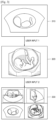
- the medical diagnostic apparatus 100 may display, on a screen, a 2D ultrasound image 310 of an embryo, a 3D ultrasound image 320 corresponding to the 2D ultrasound image 310 of the embryo based on a "user input 1", and a 4-segmented image 330 corresponding to the 3D ultrasound image 320 of the embryo based on a "user input 2".
- the medical diagnostic apparatus 100 may store a history of a plurality of operating states corresponding to "user input 1" and "user input 2.”
- FIGS. 4A , 4B , 5A , and 5B illustrate a method of operating the medical diagnostic apparatus 100 based on a history of a plurality of operating states illustrated in FIG. 3 .
- FIGS. 4A and 4B illustrate an example of a screen provided by the medical diagnostic apparatus 100 that provides a function of sequentially returning an operating state, according to an embodiment of the present invention.
- the medical diagnostic apparatus 100 may provide a GUI 420 supporting a function of moving to a state previous to a current operating state and a GUI 430 supporting a function of moving to a next state to the current operating state.
- the medical diagnostic apparatus 100 provides a 4-segmented image 410 about an embryo by using a medical image display method.
- the medical diagnostic apparatus 100 may receive a recovery input via which the GUI 420 is selected and modify an operating state thereof just before an operating state, to a current operating state.
- the medical diagnostic apparatus 100 returns to an operating state just before a current operating state (that is, a state before an operation corresponding to "user input 2" which is a recent user input in the history is performed) based on an input via which the GUI 420 is selected in FIG. 4A , thereby providing an 3D ultrasound image 440 of the embryo.
- FIGS. 5A and 5B illustrate an example of a screen provided by using the medical diagnostic apparatus 100 that provides functions of displaying a history of modification of an operating state of the medical diagnostic apparatus 100 on a screen and returning to a predetermined operating state on a history based on a recovery input about the displayed history, according to an embodiment of the present invention.
- the medical diagnostic apparatus 100 may display a history of modification of an operating state of the medical diagnostic apparatus 100 on a predetermined area 520 of a screen.
- a history displayed on the screen may include icons 521, 522, and 523 corresponding to a plurality of operating states included in the history.
- the medical diagnostic apparatus 100 may modify a current operating state thereof to an operating state corresponding to the selected icon.
- the medical diagnostic apparatus 100 provides a 4-segmented image 510 of an embryo by using a medical image displaying method. Solid letters within the icon 523 indicate that an operating state corresponding to the icon 523 is a current operating state.
- the medical diagnostic apparatus 100 may modify an operating state thereof to an operating state corresponding to the icon 521 by receiving a recovery input via which the icon 521 from among the icons 521, 522, and 523 corresponding to a plurality of operating states is selected.
- the medical diagnostic apparatus 100 When an input via which the icon 521 is selected is received in FIG. 5A , the medical diagnostic apparatus 100 returns to an operating state corresponding to the icon 521 (that is, an operating state before operations corresponding to "user input 1" and “user input 2" are performed) as illustrated in FIG. 5B , thereby providing a 2D ultrasound image 540 of the embryo. Solid letters within the icon 521 in FIG. 5B indicate that an operating state corresponding to the icon 521 is a current operating state.
- the medical diagnostic apparatus 100 may modify an operating state thereof by modifying a displaying method of displaying a medical image.
- the embodiments of the present invention are not limited thereto, and the medical diagnostic apparatus 100 may also modify an operating state thereof by modifying a parameter applied to a medical image.
- FIGS. 6A , 6B , 6C , 7, 8A, 8B , and 8C a method of operating the medical diagnostic apparatus 100 according to the current embodiment of the present invention will be described in detail with reference to FIGS. 6A , 6B , 6C , 7, 8A, 8B , and 8C .
- FIGS. 6A , 6B , and 6C illustrate an example of a screen displayed according to another embodiment of the present invention, in which an operating state that is modified based on user inputs to modify parameters is stored as a history.
- the medical diagnostic apparatus 100 may display a GUI 620 through which a parameter applied to the medical image 610 is input by a user.
- a medical image displayed on the screen of FIGS. 6A , 6B , and 6C is an ultrasound 2D B mode image
- the embodiments of the present invention are not limited thereto.
- the GUI 620 through which a parameter applied to the medical image 610 is to be input, may include a UI 621 through which a frequency of an ultrasound signal transmitted from a probe in order to obtain the medical image 610 is received, a UI 622 through which a parameter value applied to average a current image and an image just before the current image is received, a UI 623 through which a ratio between a minimum value and a maximum value of an image data signal is received in order to adjust a contrast of the medical image 610, a UI 624 through which a degree of eliminating noise or echo is received in order to make the medical image 610 clear, a UI 625 through which a set up value for setting up a size of the medical image 610 is received, and a UI 626 through which a set up value for setting the number of focusing points for obtaining the medical image 610 is received.
- the embodiments of the present invention are not limited thereto, and it is
- the medical diagnostic apparatus 100 may modify an operating state of the medical diagnostic apparatus 100 from the first state illustrated in FIG. 6A to the second state illustrated in FIG. 6B by modifying a parameter applied to a medical image.
- FIG. 6A illustrates an example in which a Gen (General) mode in which a general frequency is set as a frequency value of a transmission ultrasound signal is selected on the UI 621.
- FIG. 6B illustrates an example in which a Res (Resolution) mode in which a relatively high frequency is set as a frequency value of a transmission ultrasound signal is selected on the UI 621.
- the medical diagnostic apparatus 100 may modify an operating state thereof by receiving a user input through which a frequency value of a transmission ultrasound signal is modified from a general frequency to a relatively high frequency.
- FIG. 6A illustrates that "10" is input to the UI 622 as a parameter value applied to average a current image and an image just before the current image.
- FIG. 6B illustrates that "0" is input to the UI 622 as a parameter applied to image averaging.
- the medical diagnostic apparatus 100 may modify an operating state thereof by receiving a user input through which the parameter value applied to the image averaging is modified from "10" to "0.”
- FIG. 6A illustrates that "2" is input to the UI 626 as a set up value for setting the number of foci for obtaining the medical image 610.
- FIG. 6B illustrates that "3" is input to the UI 626 as a set up value of the foci.
- the medical diagnostic apparatus 100 may modify an operating state thereof by receiving a user input through which a set up value of the foci is modified from "2" to "3.”
- the medical diagnostic apparatus 100 displaying FIG. 6B may receive a recovery input from the user to display a screen as illustrated in FIG. 6C .
- the medical diagnostic apparatus 100 may return to a predetermined state from among a plurality of operating states included in a history based on a recovery input of a user. For example, the medical diagnostic apparatus 100 may operate an operating state thereof from an operating state just before a current operating state. Accordingly, the medical diagnostic apparatus 100 may return to an operating state before a user input through which a set up value of the number of foci is modified from "2" to "3" is received, which is an operating state just before a current operating state corresponding to FIG. 6B . That is, as illustrated in FIG. 6C , the medical diagnostic apparatus 100 may return the set up value of the number of foci which is modified to "3" to "2" based on the recovery input.
- a user may easily control the medical diagnostic apparatus 100 according to the current embodiment of the present invention such that the medical diagnostic apparatus 100 returns to a previous operating state, just by inputting a recovery input.
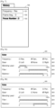
- the medical diagnostic apparatus 100 may display a history 720 of an operating state that is stored.
- the medical diagnostic apparatus 100 may display a history related to modification of an operating state of the medical diagnostic apparatus 100 on a predetermined area of the screen.
- the history 720 displayed on the screen may include icons 721, 722, and 723 respectively corresponding to a plurality of operating states that are modified based on user inputs.
- FIG. 7 In FIG. 7 , a history 720 showing an operating state of the medical diagnostic apparatus 100 from the operating state illustrated in FIG. 6A to the operating state illustrated in FIG. 6B is illustrated.
- the medical diagnostic apparatus 100 may store parameter values that are input by a user in order to modify an operating state thereof, and may output the parameter values on the screen.
- the medical diagnostic apparatus 100 may receive a recovery input via which one of the icons 721, 722, and 723 corresponding to a plurality of operating states included in the history 720 to thereby modify an operating state thereof corresponding to the selected icon.
- solid letters within the icon 723 indicate that an operating state corresponding to the icon 523 is a current operating state. That is, the history 720 illustrated in FIG. 7 corresponds to the operating state of the medical diagnostic apparatus 100 illustrated in FIG. 6B .
- the medical diagnostic apparatus 100 may receive a recovery input via which the icon 722 from among the icons 721, 722, and 723 corresponding to a plurality of operating states is selected, to thereby modify an operating state thereof corresponding to the icon 722.
- the medical diagnostic apparatus 100 may return to an operating state corresponding to the icon 722 as illustrated in FIG. 6C (that is, an operating before a user input via which a set up value of the number of foci is modified from "2" to "3" is received), thereby returning the set up value of the number of foci to a set up value of the past.
- FIGS. 8A, 8B , and 8C illustrate an example of a screen provided by the medical diagnostic apparatus 100 according to an embodiment of the present invention, in which an operating state of the medical diagnostic apparatus that is modified based on user inputs for modifying a parameter is stored as a history.
- the medical diagnostic apparatus 100 may display a GUI 820 via which a parameter applied to a medical image is received from a user, on a screen.
- FIGS. 8A, 8B , and 8C illustrate an example where a medical image displayed on a screen is an ultrasound color Doppler mode, but the embodiments of the present invention are not limited thereto.
- the GUI 820 through which a parameter applied to the medical image 810 is to be input, may include a UI 821 through which a frequency of an ultrasound signal transmitted from a probe in order to obtain a medical image is received, a UI 822 through which a set up value for adjusting a transmission angle of an ultrasound transmitted from a probe is received, a UI 823 through which a blending level applied when overlapping a color Doppler image and a B mode image and providing the overlapped image is received, a UI 824 through which a blocking frequency value in regard to high band pass filtering of ultrasound image received at the probe is received, and a UI 825 through which a brightness limit value of a B mode area that is provided while being overlapped with a color Doppler image in order to adjust a range where the color Doppler image is displayed, is received.
- the embodiments of the present invention are not limited thereto, and it is obvious to one of ordinary skill in the
- the medical diagnostic apparatus 100 may modify an operating state thereof from the first state illustrated in FIG. 8A to the second state illustrated in FIG. 8B by modifying a parameter applied to a medical image.
- FIG. 8A illustrates an example where a "None" mode is selected, in which a transmission angle of an ultrasound signal is adjusted such that an area of interest is set as a front surface, on the UI 822.
- FIG. 8B illustrates an example where a "Right" mode is selected, in which a transmission angle of an ultrasound is adjusted such that an area of interest is set as a right side, on the UI 822.
- the medical diagnostic apparatus 100 may modify an operating state thereof by receiving a user input via which an area of interest is modified from a front surface to a right side, by adjusting a transmission angle of an ultrasound signal.
- FIG. 8A illustrates an example where "24%" is input to the UI 823 as a mixture ratio of a color Doppler image and a B mode image.
- FIG. 8A illustrates an example where "0%” is input to the UI 823 as a mixture ratio of a color Doppler image and a B mode image.
- the medical diagnostic apparatus 100 may modify an operating state thereof by receiving a user input via which a mixture ratio of a color Doppler image and a B mode image is modified from "24%" to "0%.”
- FIG. 8A illustrates an example where "24" is input to the UI 825 as a brightness limit of a B mode area which is provided while being overlapped with a color Doppler image.
- FIG. 8B illustrates an example where "15" is input to the UI 825 as a brightness limit of a B mode area which is provided while being overlapped with a color Doppler image.
- the medical diagnostic apparatus 100 may modify an operating state thereof by receiving a user input via which a brightness limit is modified from "24" to "15.”
- the medical diagnostic apparatus 100 that displays FIG. 8B may receive a recovery input from a user to display a screen as illustrated in FIG. 8C .
- the medical diagnostic apparatus 100 may return to a predetermined state from among a plurality of operating states included in a history based on the recovery input of the user.
- the medical diagnostic apparatus 100 may modify an operating state thereof such that a parameter value is recovered by a predetermined value that is determined based on a user set up.
- FIG. 8C illustrates an example where a parameter value is returned by "3" with respect to a brightness limit value based on a recovery input.
- the medical diagnostic apparatus 100 may modify a brightness limit from "24" to "15” based on a user input, and may return from "15" to "24” by "3" based on the recovery input.
- a user may easily control the medical diagnostic apparatus 100 according to the current embodiment of the present invention such that the medical diagnostic apparatus 100 returns to a previous operating state, just by inputting a recovery input.
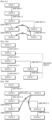
- FIGS. 9A, 9B , 9C, 10A, and 10B are views to explain that an operating state of the medical diagnostic apparatus 100 is stored based on a tree structure, according to embodiments of the present invention.
- the medical diagnostic apparatus 100 modifies "state 1" to "state 5" based on a plurality of user inputs (that is, user inputs 1 through 4).
- the medical diagnostic apparatus 100 stores a plurality of operating states respectively corresponding to user inputs (that is, states 1 through 5) as a history of the medical diagnostic apparatus 100.
- the medical diagnostic apparatus 100 selects "state 3" from among a plurality of operating states included in a history based on "recovery input 1" and modify an operating state thereof from “state 5" to "state 3" as illustrated in FIG. 6 .
- the medical diagnostic apparatus 100 may modify an operating state thereof based on an additionally input user input. Also, an operating state of the medical diagnostic apparatus 100 that is modified based on a user input that is additionally received may also be stored as a history of the medical diagnostic apparatus 100.
- a medical diagnostic apparatus which stores a history according to the conventional, sequential storage method stores "state 6" and "state 7" instead of "state 4" and "state 5" which are stored as operating states after "state 3" when storing a history of operating states respectively corresponding to "user input 5" and "user input 6.” That is, as operating states after "state 3", "state 6" and “state 7" are stored, and the previously stored "state 4" and "state 5" are removed.
- the medical diagnostic apparatus which stores a history according to the conventional, sequential storage method is not able to return from "state 7" to "state 4" or "state 5" based on a recovery input.
- FIG. 9C is a diagram to explain storage of a history of modification of an operating state of the medical diagnostic apparatus 100 according to an embodiment of the present invention, based on a tree structure.
- a tree structure refers to a type of data structure in which nodes that designate information are branched off like branches with respect to an uppermost root node as a vertex.
- the medical diagnostic apparatus 100 that stores a history based on a tree structure determines a first state as an upper mode, and determines at least one operating state that is modified by sequential first user inputs, as a subnode of the first state.
- the medical diagnostic apparatus 100 stores a history based on a tree structure that is formed of the upper mode and the subnode.
- the medical diagnostic apparatus 100 modifies an operating state thereof from “state 5" to "state 3.” After modifying the operating state from “state 5" to "state 3," the medical diagnostic apparatus 100 receives "user input 5" and "user input 6" as illustrated in FIG. 9B .
- the medical diagnostic apparatus 100 modifies an operating state thereof from “state 3" to "state 7" based on "user input 5" and "user input 6.”
- the medical diagnostic apparatus 100 stores a history of operating states that respectively correspond to "user input 5" and "user input 6" (that is, state 6 and state 7).
- the medical diagnostic apparatus 100 when storing a history of operating states respectively corresponding to "user input 5" and "user input 6," the medical diagnostic apparatus 100 renews a history such that "state 6" and “state 7" are included as subnodes of "state 3" in addition to “state 4" and “state 5.” That is, unlike the sequential storage method illustrated in FIG. 9B , according to a storage method based on a tree structure, when storing "state 6" and “state 7,” “state 4" and “state 5" are not removed.
- the medical diagnostic apparatus 100 may modify an operating state thereof "state 7" to "state 4" or "state 5" based on a received recovery input.
- the medical diagnostic apparatus 100 of the current embodiment of the present invention by storing a history according to a tree structure, the medical diagnostic apparatus 100 may return to any operating state of the past.
- the medical diagnostic apparatus 100 may receive "user input 7" as illustrated in FIG. 10B .
- the medical diagnostic apparatus 100 may modify an operating state thereof from “state 2" to “state 8" based on "user input 7.”
- the medical diagnostic apparatus 100 may store a history of an operating state corresponding to "user input 7" (that is, state 8).
- the medical diagnostic apparatus 100 may renew a history such that "state 8" is included as a subnode of "state 2" in addition to “state 3" and "state 7.” That is, according to a storage method based on a tree structure, the medical diagnostic apparatus 100 does not remove “state 3" through “state 7" while storing "state 8.” Accordingly, as illustrated in FIG. 10B , the medical diagnostic apparatus 100 may modify an operating state thereof from “state 8" to "state 4" or "state 6" based on a received recovery input.
- the medical diagnostic apparatus 100 may store a history of operating states based on a tree structure.
- the medical diagnostic apparatus 100 may display a history stored based on a tree structure as a folder image.
- the history displayed on the screen of the medical diagnostic apparatus 100 may include icons corresponding to operating states included in the history and icons corresponding to operating states which are subnodes in a folder corresponding to a predetermined operating state which is an upper node.
- the medical diagnostic apparatus 100 having an operating state corresponding to FIG. 10B may display a history such that folders respectively corresponding to "state 3" and “state 8" are included in a folder corresponding to "state 2.” Also, the medical diagnostic apparatus 100 having an operating state corresponding to FIG. 10B may display "state 4" and "state 6" to be included in a folder corresponding to "state 3.”
- the medical diagnostic apparatus 100 may be classified as an ultrasound diagnostic apparatus, an X-ray imaging device, a computed tomography (CT) imaging device, and an magnetic resonance (MR) imaging device according to a medical image each apparatus supports.
- CT computed tomography
- MR magnetic resonance
- an ultrasound diagnostic apparatus is noninvasive and non-destructive, and is thus widely used in the medical field for obtaining information about the inside of an object.
- An ultrasound diagnostic apparatus is capable of providing a high resolution image of an inside of an object without a surgical operation whereby the object is immediately cut to be observed, and is thus used in the medical field with high importance.
- An ultrasound diagnostic apparatus transmits an ultrasound signal to an object while a probe is in contact with a surface of the object, and receives an ultrasound signal reflected by the object (hereinafter referred to as an echo signal).
- An ultrasound system forms an ultrasound image of the object based on the echo signal received by using the probe, and displays the ultrasound image by using a display unit.
- an ultrasound diagnostic apparatus may form and display a B (brightness) mode image on which an intensity of an echo signal reflected from an object is expressed in brightness or a D (Doppler) image on which a Doppler component extracted from an echo signal is expressed in a color or a waveform.
- B brightness
- D Doppler
- FIG. 11 is a block diagram illustrating an ultrasound diagnostic apparatus 1000 to which a medical diagnostic apparatus according to an embodiment of the present invention may be applied.
- the method of operating the medical diagnostic apparatus 100 according to the current embodiment of the present invention may be performed by using the ultrasound diagnostic apparatus 1000 illustrated in FIG. 10 , and the medical diagnostic apparatus 100 may be included in the ultrasound diagnostic apparatus 1000 illustrated in FIG. 10 .
- the medical diagnostic apparatus 100 of FIG. 1 may perform some or all of functions that are performed by using the ultrasound diagnostic apparatus 1000 of FIG. 10 .
- the display unit 110 of FIG. 1 may correspond to a display unit 1700 of FIG. 10
- the user input unit 120 of FIG. 1 may correspond to an input unit 1500 of FIG. 10
- the storage unit 130 of FIG. 1 may correspond to a memory 1400 of FIG. 10 .
- the controller 140 of FIG. 1 may include some components or functions of an ultrasound transmitting and receiving unit 1100, an image processor 1200, a communication unit 1300, and a controller 1600 of FIG. 10 .
- the ultrasound diagnostic apparatus 1000 may include a probe 1020, the ultrasound transmitting and receiving unit 1100, the image processor 1200, the communication unit 1300, the memory 1400, the input unit 1500, and the controller 1600, and these components may be connected to one another via a bus 700.
- the transmitting unit 1110 supplies a driving signal to the probe 1020, and includes a pulse generator 1112, a transmission delay unit 1114, and a pulser1116.
- the pulse generator 1112 generates a pulse for forming a transmission ultrasound according to a predetermined pulse repetition frequency (PRF), and the transmission delay unit 1114 applies a delay time for determining a transmission directionality to a pulse.
- PRF pulse repetition frequency
- Each pulse to which a delay time is applied corresponds to each of a plurality of piezoelectric vibrators included in the probe 1020.
- the pulser 1116 applies a driving signal (or a driving pulse) to the probe 1020 at a timing corresponding to respective pulses to which a delay time is applied.
- the receiving unit 1120 processes an echo signal received from the probe 1020 to generate ultrasound data, and may include an amplifier 1122, an analog digital converter (ADC) 1124, a reception delay unit 1126, and a summing unit 1128.
- the amplifier 1122 amplifies an echo signal for each channel, and the ADC 1124 converts the amplified echo signal from analog to digital or vice versa.
- the reception delay unit 1126 applies a delay time for determining reception directionality, to the echo signal which is obtained by digital conversion, and the summing unit 1128 sums up the echo signals that are processed by using the reception delay unit 1126 to generate ultrasound data.
- the image processor 1200 generates an ultrasound image through a scan conversion process with respect to ultrasound data generated by using the ultrasound transmitting and receiving unit 1100 and displays the ultrasound image.
- a B mode processor 1212 in a data processor 1210 extracts a B mode component from ultrasound data and processes the same.
- An image generating unit 1220 may generate an ultrasound image whose signal intensity is expressed as brightness, based on the B mode component that is extracted by using the B mode processor 1212.
- a Doppler processor 1214 in the data processor 1210 may extract a Doppler component from ultrasound data, and the image generating unit 1220 may generate a Doppler image in which motion of an object is expressed in color or waveform based on the extracted Doppler element.
- the image generating unit 1220 may generate a 3D ultrasound image by using a volume rendering process with respect to volume data, and may also generate an elastic image which expresses a degree of deformation of the object 1010 according to a pressure as an image. Furthermore, the image generating unit 1220 may express various additional information as text or graphics on the ultrasound image. Meanwhile, the ultrasound image may be stored in the memory 1400.
- the communication unit 1300 is connected to a network 1030 in a wired or wireless manner to perform communication with an external device or a server.
- the communication unit 1300 may exchange data with a hospital server or other medical device in a hospital, which are connected through a Picture Archiving and Communication System (PACS).
- PPS Picture Archiving and Communication System
- the communication unit 1300 may perform data communication according to Digital Imaging and Communications in Medicine (DICOM).
- DICOM Digital Imaging and Communications in Medicine
- the communication unit 1300 may transmit or receive data related to diagnosis of an object such as an ultrasound image or ultrasound data of an object, and may also transmit or receive a medical image captured by using other medical devices such as CT, MRI, or X-ray. Furthermore, the communication unit 1300 may receive information about a diagnosis history or a treatment schedule of a patient from a server and use the information in diagnosis of an object. Moreover, the communication unit 1300 may perform data communication with not only a server or a medical device in a hospital but with a mobile terminal of a doctor or a patient.
- the communication unit 1300 may be connected to the network 1030 in a wired or wireless manner to transmit or receive data to or from a server 1032, a medical device 1034, or a mobile terminal 1036.
- the communication unit 1300 may include at least one component that allows communication with an external device, and may include, for example, a short range communication module 1310, a wired communication module 1320, and a mobile communication module 1330.
- the short range communication module 1310 refers to a module for short range communication within a predetermined distance.
- Examples of short range communication according to an embodiment of the present invention include, without limitation, Wireless LAN, Wi-Fi, Bluetooth, Zigbee, Wi-Fi Direct (WFD), Ultra Wideband (UWB), Infrared Data Association (IrDA), Bluetooth Low Energy (BLE), and Near Field Communication (NFC).
- the wired communication module 1320 refers to a module for communication by using an electrical signal or an optical signal.
- Examples of wired communication technology include using a pair cable, a coaxial cable, an optical fiber cable, or an Ethernet cable.
- the mobile communication module 1330 transmits or receives a wireless signal to or from at least one selected from the group consisting of a base station, an external terminal, or a server on a mobile communication network.
- a wireless signal may include a sound call signal, a video conference call signal, or various types of data according to text or multimedia message transmission and reception.
- the memory 1400 stores various information that is processed in the ultrasound diagnostic apparatus 1000.
- the memory 1400 may store medical data related to diagnosis of an object, such as input or output ultrasound data or an ultrasound image, and may also store an algorithm or a program executed in the ultrasound diagnostic apparatus 1000.
- the memory 1400 may be implemented in various types of storage media such as a flash memory, a hard disk, or an electrically erasable programmable read-only memory (EEPROM). Also, the ultrasound diagnostic apparatus 1000 may also operate a web storage or a cloud server that performs a function of the memory 1400 on a web.
- storage media such as a flash memory, a hard disk, or an electrically erasable programmable read-only memory (EEPROM).
- EEPROM electrically erasable programmable read-only memory
- the ultrasound diagnostic apparatus 1000 may also operate a web storage or a cloud server that performs a function of the memory 1400 on a web.
- the input unit 1500 refers to a unit that receives data for controlling the ultrasound diagnostic apparatus 1000 from a user.
- Examples of the input unit 1500 include, without limitation, a key pad, a mouse, a touch panel, a touch screen, a track ball, and a jog switch, and may further include various input units such as an electrocardiogram measurement module, a respiration measurement module, a sound recognition sensor, a gesture recognition sensor, a fingerprint recognition sensor, an iris recognition sensor, a depth sensor, or a distance sensor.
- the controller 1600 controls the overall operation of the ultrasound diagnostic apparatus 1000. That is, the controller 1600 may control operations to be performed among the probe 1020, the ultrasound transmitting and receiving unit 1100, the image processor 1200, the communication unit 1300, the memory 1400, and the input unit 1500 illustrated in FIG. 11 .
- Some or all of the probe 1020, the ultrasound transmitting and receiving unit 1100, the image processor 1200, the communication unit 1300, the memory 1400, the input unit 1500, and the controller 1600 may be operated via a software module but are not limited thereto, and some of the above components may also operate via hardware.
- at least some of the ultrasound transmitting and receiving unit 1100, the image processor 1200, and the communication unit 1300 may be included in the controller 1600, but the ultrasound diagnostic apparatus 1000 is not limited to the above implementation structure.
- An embodiment of the present invention may also be realized in a form of a recording medium including commands executable by a computer, such as a program module executed by a computer.
- a computer-readable recording medium may be an arbitrary available medium accessible by a computer, and may be any one of volatile, nonvolatile, separable, and non-separable media.
- examples of the computer-readable recording medium may include a computer storage medium and a communication medium. Examples of the computer storage medium include volatile, nonvolatile, separable, and non-separable media realized by an arbitrary method or technology for storing information about a computer-readable command, a data structure, a program module, or other data.
- the communication medium may include a computer-readable command, a data structure, a program module, other data of a modulated data signal, such as carrier waves, or other transmission mechanisms, and may be an arbitrary information transmission medium.
Landscapes
- Health & Medical Sciences (AREA)
- Life Sciences & Earth Sciences (AREA)
- Engineering & Computer Science (AREA)
- Physics & Mathematics (AREA)
- Veterinary Medicine (AREA)
- Biophysics (AREA)
- General Health & Medical Sciences (AREA)
- Pathology (AREA)
- Public Health (AREA)
- Biomedical Technology (AREA)
- Heart & Thoracic Surgery (AREA)
- Medical Informatics (AREA)
- Molecular Biology (AREA)
- Surgery (AREA)
- Animal Behavior & Ethology (AREA)
- Nuclear Medicine, Radiotherapy & Molecular Imaging (AREA)
- Radiology & Medical Imaging (AREA)
- Human Computer Interaction (AREA)
- Ultra Sonic Daignosis Equipment (AREA)
- Gynecology & Obstetrics (AREA)
- Pregnancy & Childbirth (AREA)
- Computer Networks & Wireless Communication (AREA)
- Computer Graphics (AREA)
- General Engineering & Computer Science (AREA)
Description
- One or more embodiments of the present invention relate to a medical diagnostic apparatus and a method of operating the medical diagnostic apparatus, and more particularly, to a medical diagnostic apparatus having functions of storing history of an operating state of the medical diagnostic apparatus that is modified according to a user input and returning to a predetermined operating state included in the history, and a method of operating the medical diagnostic apparatus.
- A medical diagnostic apparatus displays a medical image so as to provide a user with information about diagnosis of a disease and information for treatment. The medical diagnostic apparatus may be an additional apparatus separated from an apparatus for obtaining a medical image or may include an apparatus for obtaining a medical image. An apparatus for obtaining a medical image irradiates a predetermined signal toward an object and obtains a medical image about a cross-section or hematocele of the object by using a signal reflected from the object or a signal that has transmitted through the object.
- For example, an apparatus for obtaining a medical image may obtain an ultrasound image, an X-ray image, a computerized tomography (CT) image, a magnetic resonance (MR) image, or a positron emission tomography (PET) image.
- When a user controls a medical diagnostic apparatus such that the medical diagnostic apparatus performs operations that require precise user manipulation, to return to a previous operating state, the user has to input a command for restoring previously executed operations or execute each operation from an initial state. However, if the manipulation process is complicated, it is difficult for the user to remember all of inputs whereby all of corresponding operations are restored.
- Also, if a precise manipulation is required, it is difficult in reality to operate a medical diagnostic apparatus such that the medical diagnostic apparatus returns to a previous operating state.
- In addition to above referenced prior art, here
EP-2 1455 580 US-2011/137836 .EP 2 1455 580US2011/137836 is directed to a sensor network system that includes a sensor node for measuring living organism information. In particular, it relates to a technology of obtaining an activity history of a monitored subject with the use of a sensor node worn by the monitored subject, and analyzing an activity pattern of the monitored subject from the activity history. - One or more embodiments of the present invention include a medical diagnostic apparatus having functions of storing a history of an operating state of the medical diagnostic apparatus and returning to a previous state from among a plurality of operating states included in the history, and a method of operating the medical diagnostic apparatus.
- According to one or more embodiments of the present invention, a method of operating a medical diagnostic apparatus that displays a medical image, includes steps defined in the appended independent method claim.
- According to one or more embodiments of the present invention, a medical diagnostic apparatus includes features defined in the appended independent apparatus claim.
- According to one or more embodiments of the present invention, a non-transitory computer readable recording medium having embodied thereon a program for executing the method described above is included. Preferred embodiments may be defined in dependent claims, and/or be apparent from the following embodiment description.
-
-
FIG. 1 is a block diagram illustrating a medical diagnostic apparatus according to an embodiment -
FIG. 2 is a flowchart illustrating a method of operating a medical diagnostic apparatus according to an embodiment; -
FIG. 3 is a schematic view to explain modification of an operating state of a medical diagnostic apparatus based on user inputs, according to an embodiment; -
FIGS. 4A and4B illustrate an example of a screen displayed according to an embodiment of the present invention; -
FIGS. 5A and5B illustrate an example of a screen displayed according to another embodiment; -
FIGS. 6A ,6B , and6C illustrate an example of a screen displayed according to another embodiment; -
FIG. 7 illustrates an example of a screen on which an operating state history of a medical diagnostic apparatus that is stored is displayed, according to an embodiment -
FIGS. 8A, 8B , and8C illustrates an example of a parameter input graphic user interface (GUI) displayed according to an embodiment; -
FIGS. 9A, 9B ,9C, 10A, and 10B are views to explain that an operating state of a medical diagnostic apparatus is stored based on a tree structure, according to embodiments of the present invention; and -
FIG. 11 is a block diagram illustrating an ultrasound diagnostic apparatus to which a medical diagnostic apparatus according to an embodiment. - Reference will now be made in detail to embodiments, examples of which are illustrated in the accompanying drawings, wherein like reference numerals refer to the like elements throughout. In this regard, the present embodiments may have different forms and should not be construed as being limited to the descriptions set forth herein. Accordingly, the embodiments are merely described below, by referring to the figures, to explain aspects of the present description. Expressions such as "at least one of," when preceding a list of elements, modify the entire list of elements and do not modify the individual elements of the list.
- Hereinafter, the present invention will be described in detail by explaining exemplary embodiments of the invention with reference to the attached drawings. The invention may, however, be embodied in many different forms, and should not be construed as being limited to the embodiments set forth herein; rather, these embodiments are provided so that this disclosure will be thorough and complete, and will fully convey the concept of the invention to those skilled in the art. In the following description, well-known functions or constructions are not described in detail since they would obscure the invention with unnecessary detail, and like reference numerals in the drawings denote like or similar elements throughout the specification.
- Throughout the specification, it will also be understood that when an element is referred to as being "connected to" another element, it can be directly connected to the other element, or it can be electrically connected to the other element and intervening elements may be present. Also, when a part "includes" an element, unless there is a particular description contrary thereto, the part can further include other elements, not excluding the other elements.
- Throughout the specification, a term 'object' may be an animated object or an inanimated object, which is displayed via an image. Also, the object may be a part of a human body and may include the liver, the heart, the womb, the brain, the breast, the abdominal region, or the like, a fetus, or a cross-section of a part of a human body. Throughout the specification, a "user" may be, without limitation, a medical expert including a doctor, a nurse, a medical laboratory technologist, a sonographer, a medical image expert, or the like.
- A medical diagnostic apparatus provides a medical image about an object and is used in diagnosis and treatment of a disease. A medical diagnostic apparatus may obtain image data about an object, generate a medical image based on the image data, and display the medical image on a screen.
- A user may operate a medical diagnostic apparatus such that the medical diagnostic apparatus transmits or receives a predetermined signal to or from an object in order to obtain image data, or sets various parameters needed to generate a medical image from image data, or modifies a displaying method of displaying the medical image on a screen. According to the conventional art, it is burdensome that after operating a medical diagnostic apparatus, a user has to operate a medical diagnostic apparatus from an initial state again in order to return to a previous state.
- The present invention has been designed to solve the problem of the conventional art.
-
FIG. 1 is a block diagram illustrating a medicaldiagnostic apparatus 100 according to an embodiment of the present invention. - The medical
diagnostic apparatus 100 according to the current embodiment of the present invention includes adisplay unit 110, auser input unit 120, astorage unit 130, and acontroller 140. - The
display unit 110 displays a medical image based on an operating state of the medicaldiagnostic apparatus 100. Thedisplay unit 110 may further display a history of the medicaldiagnostic apparatus 100 stored in thestorage unit 130. Thedisplay unit 110 may display not only a medical image generated by using the medicaldiagnostic apparatus 100 but also various information processed in the medicaldiagnostic apparatus 100 through a graphic user interface (GUI). - The
user input unit 120 receives a user input. A user input may refer to data or a signal that is input to the medicaldiagnostic apparatus 100 by a user. In detail, a user input may refer to data or a signal through which an event, which is a motive of initiating or completing a predetermined operation, is generated. A user input may be received through, for example, a control panel, a keyboard, and a touch panel included in the medicaldiagnostic apparatus 100. - For example, based on a first user input via which a medical image being displayed on a screen is rotated, moved, or expanded or reduced, the medical
diagnostic apparatus 100 may output a new medical image that is obtained by rotating, moving or expanding or reducing a currently displayed medical image. - The
user input unit 120 refers to a unit through which a user inputs data or a signal for operating the medicaldiagnostic apparatus 100. Theuser input unit 120 according to the current embodiment of the present invention sequentially receives a plurality of user inputs. Theuser input unit 120 may further include a recovery input via which an operating state of the medical diagnostic apparatus is modified to a predetermined operating state included in the history. - Examples of the
user input unit 120 include, without limitation, a key pad, a dome switch, a mouse, a sensor, a knob button, a touch pad (capacitive overlay type, resistive overlay type, infrared beam type, integral strain gauge type, surface acoustic wave type, piezoelectric type or the like), a jog wheel, and a jog switch. Also, a touch pad which is in a layered structure with a display panel of thedisplay unit 110 may be referred to as a touch screen. - In addition, the
user input unit 120 may include a sensor that receives a temperature input, a pressure input, or a sound input or the like. - The
storage unit 130 stores a history of a plurality of operating states of the medicaldiagnostic apparatus 100 respectively corresponding to user inputs. Thestorage unit 130 may store, from among a plurality of operating states, at least one operating state corresponding at least one user input selected by using thecontroller 140, as a history. Also, thestorage unit 130 may store image data that is used to generate a medical image. - The
controller 140 controls the overall operation of the medicaldiagnostic apparatus 100, and controls thedisplay unit 110, theuser input unit 120, and thestorage unit 130 such that a medical image is displayed based on an operating state of the medicaldiagnostic apparatus 100. Also, thecontroller 140 may include a processor (not shown) that generates a medical image based on image data. Image data that thecontroller 140 uses to generate a medical image may be obtained from thestorage unit 130 or may be generated by using thecontroller 140 based on a signal received from an object in response to a signal that is transmitted to the object, or may be received from an external device or an external server. - Also, the
controller 140 modifies an operating state of the medicaldiagnostic apparatus 100 based on user inputs. For example, thecontroller 140 may modify an operating state of the medical diagnostic apparatus from a first state to a second state based on a plurality of first user inputs that are sequentially received. - The
controller 140 may modify an operating state of the medical diagnostic apparatus by modifying a displaying method in which a medical image is displayed or by modifying a parameter applied to a medical image. Thecontroller 140 may modify a displaying method, in which a medical image is displayed, by modifying the number of medical images displayed on a single screen or by modifying a 2D medical image to a 3D medical image or a 3D medical image to a 2D medical image. - Alternatively, when a displayed medical image is an ultrasound image, the
controller 140 may modify a displaying method, in which a medical image is displayed, by modifying an ultrasound mode. Examples of an ultrasound mode include, without limitation, a brightness (B) mode in which an intensity of an echo signal reflected by an object is expressed by brightness, a Doppler (D) mode in which a Doppler component extracted from an echo signal is expressed by a color or a waveform, and an elastic mode in which a degree of deformation of a tissue according to a pressure applied from the outside is formed to an image. - The
controller 140 may control an operation of the medicaldiagnostic apparatus 100 such that at least one of first user inputs that is related to modification of an operating state of the medicaldiagnostic apparatus 100 is selected and that thestorage unit 130 stores an operating state corresponding to the selected, first user input as a history. A first user input related to modification of an operating state of the medicaldiagnostic apparatus 100 may refer to a first user input related to at least one selected from the group consisting of an operation of generating a medical image that is different from a medical image that the medicaldiagnostic apparatus 100 is currently displaying and an operation of displaying a medical image that is different from a medical image that the medicaldiagnostic apparatus 100 is currently displaying. - For example, the
controller 140 may store, as a history of the medicaldiagnostic apparatus 100, only first user inputs except a first user input via which storage and output of a medical image or replay of medical video images is performed. - Next, the
controller 140 may return to a previous operating state based on a recovery input. Based on the received recovery input, thecontroller 140 may select a predetermined state from among a plurality of states and return to the selected operating state. For example, thecontroller 140 may select a third state from among a plurality of operating states included in a history, and may modify an operating state of a medical diagnostic apparatus from the second state to the third state. - For example, the
controller 140 may move to a predetermined state in a stepwise manner, from among a plurality of operating states included in a history, based on a recovery input. - For example, the
controller 140 may modify a current operating state to a previous operating state just before the current operating state, from among a plurality of operating states included in a history, based on a recovery input. That is, when an operating state of the medicaldiagnostic apparatus 100 starts from "state A", passes "state B" and is modified to "state C", and a recovery input is received, thecontroller 140 may modify the operating state of the medicaldiagnostic apparatus 100 to "state B" which is an operating state just before "state C," which is a current operating state. - Alternatively, the
controller 140 may modify an operating state of the medicaldiagnostic apparatus 100 to a selected state based on a recovery input via which a predetermined state is selected from among a plurality of operating states included in a history displayed by using thedisplay unit 110. - For example, when an operating state of the medical
diagnostic apparatus 100 starts from "state A", passes "state B" and is modified to "state C", thecontroller 140 may modify, based on a recovery input via which "state A" or "state B" is selected, the operating state of the medicaldiagnostic apparatus 100 to "state A" or "state B." - As described above, the medical
diagnostic apparatus 100 according to the current embodiment of the present invention provides functions of storing a history of a plurality of operating state respectively corresponding to user inputs and returning to a predetermined operating state included in the history, thereby allowing a user to conveniently and easily operate the medicaldiagnostic apparatus 100. - Hereinafter, a method of operating the medical
diagnostic apparatus 100 will be described in detail with reference toFIG. 2 . -
FIG. 2 is a flowchart illustrating a method of operating a medicaldiagnostic apparatus 100 according to an embodiment of the present invention. - In operation S210, the medical
diagnostic apparatus 100 modifies an operating state of the medicaldiagnostic apparatus 100 from a first state to a second state based on sequential first user inputs. - A first user input may refer to a user input that is input by a user to the medical
diagnostic apparatus 100. In detail, a user input may refer to data or a signal through which an event, which is a motive of initiating or completing a predetermined operation, is generated. - A first user input may be received via, for example, a control panel, a keyboard, and a touch panel included in the medical
diagnostic apparatus 100. For example, based on a first user input via which a medical image being displayed on a screen is rotated, moved, or expanded or reduced, the medicaldiagnostic apparatus 100 may output a new medical image that is obtained by rotating, moving or expanding or reducing a currently displayed medical image. - The medical
diagnostic apparatus 100 may obtain image data, generate a medical image based on the image data, and display the medical image on a screen. - Thus, modification of an operating state of the medical
diagnostic apparatus 100 may refer to modification of a display method of displaying a medical image. - A method of displaying a medical image may be modified by modifying the number of medical images displayed on a single screen or by converting a 2D image to a 3D image or a 3D image to a 2D image. Alternatively, when the medical
diagnostic apparatus 100 is an ultrasound diagnostic apparatus that provides an ultrasound image, a method of displaying a medical image may be modified as an ultrasound mode is modified. - Also, the medical
diagnostic apparatus 100 may modify a parameter applied to a medical image from a first value to a second value, based on first user inputs. - Thus, modification of an operating state of the medical
diagnostic apparatus 100 may refer to modification of a parameter that is applied to generate a medical image based on image data or modification of a parameter that is applied to display the generated medical image. - For example, the medical
diagnostic apparatus 100 may display a 3D image displaying an object by rotating the 3D image by 90° with respect to a predetermined rotational axis based on a first user input via which a knob button on a control panel of the medicaldiagnostic apparatus 100 is rotated by a predetermined angle. - The medical
diagnostic apparatus 100 may include, as a first user input, at least one selected from the group consisting of an input via which a gain applied to a medical image displayed on a screen such as a TGC (Time Gain Compensation) is modified, an input via which a dynamic range is modified, an input via which a post process is selected, an input via which geometry applied to a medical image is modified, and an input via which a depth applied to a medical image displayed on a screen is modified. - Also, the medical
diagnostic apparatus 100 may modify an operating state thereof based on at least one selected from the group consisting of an input via which an irradiation angle of a predetermined signal irradiated to an object is adjusted, an input via which annotation, a marker, or a text is input with respect to an image displayed on a screen, and an input via which at least one selected from the group consisting of a length, a thickness, a size, and a shape of a predetermined area about an object is measured. - In operation S220, the medical
diagnostic apparatus 100 according to the current embodiment of the present invention stores a history of a plurality of operating state respectively corresponding to first user inputs. - The medical
diagnostic apparatus 100 may select at least one first user input related to an operating state of the medicaldiagnostic apparatus 100 from among first user inputs and store an operating state corresponding to the selected first user input as a history. The medicaldiagnostic apparatus 100 may obtain a medical image that is different from a currently displayed medical image, as a first user input related to modification of an operating state of the medicaldiagnostic apparatus 100, or may select only a first user input via which a medical image that is different from a currently displayed medical image is displayed on a screen. - The medical
diagnostic apparatus 100 may store only an operating state corresponding to a first user input related to modification of an operating state of the medicaldiagnostic apparatus 100, as a history of the medicaldiagnostic apparatus 100, except a first user input related to at least one selected from the group consisting of an image output through a printer, storage of an image, storage of a video, replay or a video, and production of a video. Examples of a first user input related to modification of an operating state of the medicaldiagnostic apparatus 100 may include, without limitation, an input via which a parameter related to a focus of a predetermined signal transmitted to an object is set, an input via which a depth or an expansion rate of an image displayed on a screen is set, and an input via which an image displayed on a screen is rotated. - Also, the medical
diagnostic apparatus 100 may store a history based on a tree structure. The medicaldiagnostic apparatus 100 may determine a first state as an upper node and at least one operating state that is modified via first user inputs as a subnode of the first state. The medicaldiagnostic apparatus 100 may store a history based on a tree structure formed of the determined upper node and the determined subnode. - A tree structure in which an operating state of the medical
diagnostic apparatus 100 is stored according to an embodiment of the present invention will be described in detail with reference toFIGS. 9A, 9B ,9C, 10A, and 10B . - Meanwhile, the medical
diagnostic apparatus 100 may store a history in a form that is available in an external device (for example, another medical diagnostic apparatus). An external device may modify an operating state to a predetermined operating state included in a history of the medicaldiagnostic apparatus 100 without receiving a new user input from a user by using a history stored in the medicaldiagnostic apparatus 100. Accordingly, when a complicated or precise operation is to be performed with respect to multiple medical diagnostic apparatuses, a user may achieve convenience by using the history stored in the medicaldiagnostic apparatus 100. - Also, according to an embodiment of the present invention, the medical
diagnostic apparatus 100 may repeatedly perform arbitrary operations based on a history of a plurality of operating states. That is, the medicaldiagnostic apparatus 100 may select at least two of a plurality of operating states included in a history. Then, the medicaldiagnostic apparatus 100 may repeatedly perform operations within the history such that the medicaldiagnostic apparatus 100 is repeatedly modified from one operating state to another operating state. - In operation S230, the medical
diagnostic apparatus 100 receives a recovery input. - A recovery input refers to a user input via which an operating state of the medical
diagnostic apparatus 100 is returned to a desired operating state within a history. In detail, a recovery input may refer to data or a signal through which an event, through which an operating state of the medicaldiagnostic apparatus 100 is modified to a predetermined operating state of the past. - For example, a recovery input may be received through a GUI that supports a function of sequentially returning an operating state to a desired operating state within a history.
-
FIG. 4A illustrates an example of aGUI 420 that supports a function of returning a current operating state to a previous state. The medicaldiagnostic apparatus 100 may modify an operating state of the medicaldiagnostic apparatus 100 to an operating state just before a current operating state from among a plurality of operating states included in a history, upon receiving a recovery input for selecting theGUI 420. - Alternatively, a recovery input may be received through icons that correspond to a plurality of operating states included in a history.
- As illustrated in
FIG. 5A , the medicaldiagnostic apparatus 100 may display a history related to modification of an operating state of the medicaldiagnostic apparatus 100 on apredetermined area 520 of a screen. A history displayed on a screen may includeicons icons diagnostic apparatus 100 may modify an operating state thereof to an operating state corresponding to the selected icon. - Meanwhile, the medical
diagnostic apparatus 100 may align operating states included in a history of the medicaldiagnostic apparatus 100 displayed on a screen based on at least one selected from names, time, date, an ascending order, and a descending order. - In operation S240, the medical
diagnostic apparatus 100 selects a third state from among the plurality of operating states included in a history, based on a recovery input. - The medical
diagnostic apparatus 100 according to the current embodiment of the present invention may store a history based on a tree structure. The medicaldiagnostic apparatus 100 may determine a third state as an upper node, and determine at least one operating state that is modified according to user inputs, as a subnode of a first node. Accordingly, the medicaldiagnostic apparatus 100 may determine the third state which is an operating state previous to the second state as an upper node of the second state, and store the second state and the third state within a history. - For example, the medical
diagnostic apparatus 100 may select an operating state just before the second state as a third state, from among a plurality of operating states included in a history, based on a recovery input. - Alternatively, for example, the medical
diagnostic apparatus 100 may select a third state corresponding to an input frequency or a duration time based on an input frequency or a duration time of a recovery input. - For example, when an input via which a GUI supporting a function of sequentially returning an operating state is selected n times is received, the medical
diagnostic apparatus 100 may determine that a user input, which intends to return from a current operating state to an operating state before n operations, is received. Accordingly, an operating state of the medicaldiagnostic apparatus 100 may be modified from a current operating state to an operating state that is before n operations, based on an input frequency of a recovery input. - Alternatively, for example, the medical
diagnostic apparatus 100 may receive, with respect to a history displayed on a screen, a third state from among operating states included in the history, and select a third state based on the received input. - In operation S250, the medical
diagnostic apparatus 100 modifies the operating state thereof from the second state to the selected, third state. - The medical
diagnostic apparatus 100 may modify an operating state thereof from an operating state that is just before the second state based on a recovery input, and may modify an operating state thereof to a state corresponding to an input frequency or a duration time of a recovery input. - Meanwhile, the operating state of the medical
diagnostic apparatus 100 in operation S210 may be modified from a first state in which a predetermined parameter applied to a medical image is a first value to a second state in which a predetermined parameter is a second value based on first user inputs that are sequentially received. In this case, in operation S250, the medicaldiagnostic apparatus 100 may be modified from the second state to the third state based on a recovery input, and the third state may be an operating state in which the parameter returns from the second value to the first value by a predetermined value that is determined based on a user set up. - For example, an embodiment in which the medical
diagnostic apparatus 100 is operated such that a 3D image displayed on a screen is rotated by 90° with respect to a predetermined axis by rotating a knob button on a control panel of the medicaldiagnostic apparatus 100 in a clockwise direction will be described as an example. - A state in which a 3D image is not rotated and thus a rotational angle is 0° may be regarded as a first state, and a state in which a rotational angle of a 3D image is 90° based on a first user input may be regarded as a second state. When a recovery input is received, the medical
diagnostic apparatus 100 may operate such that the 3D image that is determined based on a user set up returns, by a predetermined angle, to a state before the 3D image is rotated. That is, the medicaldiagnostic apparatus 100 may determine θ° (0 >0) based on a user setup, and every time when a recovery input is received, the medicaldiagnostic apparatus 100 may display the 3D image that is rotated by 90° by each -θ°. - That is, according to an embodiment of the present invention, just by simply inputting a recovery input, the medical
diagnostic apparatus 100 may be easily operated such that the medicaldiagnostic apparatus 100 returns to a predetermined operating state included in a history. Accordingly, according to the current embodiment of the present invention, the medicaldiagnostic apparatus 100 may search for operating states of the medicaldiagnostic apparatus 100 that are modified based on first user inputs or conveniently modify an operating state thereof to an arbitrary operating state from among a plurality of operating states included in a history. Accordingly, a user may save time needed to return to a previous operating state and achieve convenience. - Meanwhile, after modifying an operating state so as to return to a predetermined operating state included in a history based on a recovery input, the medical
diagnostic apparatus 100 may receive a new user input and modify an operating state thereof based on the new user input. - For example, the medical
diagnostic apparatus 100 may receive a second user input, and may modify an operating state of the medicaldiagnostic apparatus 100 from a third state to a fourth state based on the second user input. - A second user input may refer to a user input that is input to the medical
diagnostic apparatus 100 by a user. In detail, a second user input may refer to data or a signal through which an event which is a motive for the medicaldiagnostic apparatus 100 to initiate or complete a predetermined operation is generated. - A second user input may be received through, for example, a control panel, a keyboard, and a touch panel included in the medical
diagnostic apparatus 100. For example, based on a second user input via which a medical image being displayed on a screen is rotated, moved, or expanded or reduced, the medicaldiagnostic apparatus 100 may output, a new medical image that is obtained by rotating, moving or expanding or reducing a currently displayed medical image. - The first user input and the second user input may be user inputs that allow the medical
diagnostic apparatus 100 to perform the same operation or different operations. Also, the first user input and the second user input may be received from the same user or from different users. - The medical
diagnostic apparatus 100 that stores a history based on a tree structure may renew and store a history such that a fourth state is further included as a subnode of a third state. The medicaldiagnostic apparatus 100 that stores a history based on a tree structure stores an operating state history in parallel. - Accordingly, instead of storing the fourth state such that the fourth state which is newly added overwrites other operating states that are previously stored in a history, the medical
diagnostic apparatus 100 may store the fourth state together in addition to other operating states that are previously stored. The medicaldiagnostic apparatus 100 that stores a history based on a tree structure may modify an operating state thereof from the fourth state to the second state included in the history based on a recovery input. - Hereinafter, a method of operating the medical
diagnostic apparatus 100 according to an embodiment of the present invention will be described in detail with reference toFIGS. 3 ,4A ,4B ,5A , and5B .FIG. 3 is a schematic view to explain modification of an operating state of a medical diagnostic apparatus based on user inputs, according to an embodiment of the present invention. - As illustrated in
FIG. 3 , the medicaldiagnostic apparatus 100 may display, on a screen, a2D ultrasound image 310 of an embryo, a3D ultrasound image 320 corresponding to the2D ultrasound image 310 of the embryo based on a "user input 1", and a 4-segmentedimage 330 corresponding to the3D ultrasound image 320 of the embryo based on a "user input 2". The medicaldiagnostic apparatus 100 may store a history of a plurality of operating states corresponding to "user input 1" and "user input 2."FIGS. 4A ,4B ,5A , and5B illustrate a method of operating the medicaldiagnostic apparatus 100 based on a history of a plurality of operating states illustrated inFIG. 3 . -
FIGS. 4A and4B illustrate an example of a screen provided by the medicaldiagnostic apparatus 100 that provides a function of sequentially returning an operating state, according to an embodiment of the present invention. - The medical
diagnostic apparatus 100 may provide aGUI 420 supporting a function of moving to a state previous to a current operating state and aGUI 430 supporting a function of moving to a next state to the current operating state. - As illustrated in
FIG. 4A , the medicaldiagnostic apparatus 100 provides a 4-segmentedimage 410 about an embryo by using a medical image display method. The medicaldiagnostic apparatus 100 may receive a recovery input via which theGUI 420 is selected and modify an operating state thereof just before an operating state, to a current operating state. As illustrated inFIG. 4B , the medicaldiagnostic apparatus 100 returns to an operating state just before a current operating state (that is, a state before an operation corresponding to "user input 2" which is a recent user input in the history is performed) based on an input via which theGUI 420 is selected inFIG. 4A , thereby providing an3D ultrasound image 440 of the embryo. -
FIGS. 5A and5B illustrate an example of a screen provided by using the medicaldiagnostic apparatus 100 that provides functions of displaying a history of modification of an operating state of the medicaldiagnostic apparatus 100 on a screen and returning to a predetermined operating state on a history based on a recovery input about the displayed history, according to an embodiment of the present invention. - As illustrated in
FIG. 5A , the medicaldiagnostic apparatus 100 may display a history of modification of an operating state of the medicaldiagnostic apparatus 100 on apredetermined area 520 of a screen. A history displayed on the screen may includeicons icons diagnostic apparatus 100 may modify a current operating state thereof to an operating state corresponding to the selected icon. - As illustrated in
FIG. 5A , the medicaldiagnostic apparatus 100 provides a 4-segmentedimage 510 of an embryo by using a medical image displaying method. Solid letters within theicon 523 indicate that an operating state corresponding to theicon 523 is a current operating state. - The medical
diagnostic apparatus 100 may modify an operating state thereof to an operating state corresponding to theicon 521 by receiving a recovery input via which theicon 521 from among theicons - When an input via which the
icon 521 is selected is received inFIG. 5A , the medicaldiagnostic apparatus 100 returns to an operating state corresponding to the icon 521 (that is, an operating state before operations corresponding to "user input 1" and "user input 2" are performed) as illustrated inFIG. 5B , thereby providing a2D ultrasound image 540 of the embryo. Solid letters within theicon 521 inFIG. 5B indicate that an operating state corresponding to theicon 521 is a current operating state. - As described above with reference to
FIGS. 3 ,4A ,4B ,5A , and5B , the medicaldiagnostic apparatus 100 according to the current embodiment of the present invention may modify an operating state thereof by modifying a displaying method of displaying a medical image. However, the embodiments of the present invention are not limited thereto, and the medicaldiagnostic apparatus 100 may also modify an operating state thereof by modifying a parameter applied to a medical image. - Hereinafter, a method of operating the medical
diagnostic apparatus 100 according to the current embodiment of the present invention will be described in detail with reference toFIGS. 6A ,6B ,6C ,7, 8A, 8B , and8C . -
FIGS. 6A ,6B , and6C illustrate an example of a screen displayed according to another embodiment of the present invention, in which an operating state that is modified based on user inputs to modify parameters is stored as a history. - As illustrated in
FIGS. 6A ,6B , and6C , the medicaldiagnostic apparatus 100 may display aGUI 620 through which a parameter applied to themedical image 610 is input by a user. - While a medical image displayed on the screen of
FIGS. 6A ,6B , and6C is anultrasound 2D B mode image, the embodiments of the present invention are not limited thereto. - As illustrated in
FIGS. 6A ,6B , and6C , theGUI 620, through which a parameter applied to themedical image 610 is to be input, may include aUI 621 through which a frequency of an ultrasound signal transmitted from a probe in order to obtain themedical image 610 is received, aUI 622 through which a parameter value applied to average a current image and an image just before the current image is received, aUI 623 through which a ratio between a minimum value and a maximum value of an image data signal is received in order to adjust a contrast of themedical image 610, aUI 624 through which a degree of eliminating noise or echo is received in order to make themedical image 610 clear, aUI 625 through which a set up value for setting up a size of themedical image 610 is received, and aUI 626 through which a set up value for setting the number of focusing points for obtaining themedical image 610 is received. However, the embodiments of the present invention are not limited thereto, and it is obvious to one of ordinary skill in the art that the medicaldiagnostic apparatus 100 according to the current embodiment of the present invention may receive various parameters applied to a medical image by a user. - The medical
diagnostic apparatus 100 may modify an operating state of the medicaldiagnostic apparatus 100 from the first state illustrated inFIG. 6A to the second state illustrated inFIG. 6B by modifying a parameter applied to a medical image. -
FIG. 6A illustrates an example in which a Gen (General) mode in which a general frequency is set as a frequency value of a transmission ultrasound signal is selected on theUI 621.FIG. 6B illustrates an example in which a Res (Resolution) mode in which a relatively high frequency is set as a frequency value of a transmission ultrasound signal is selected on theUI 621. As illustrated inFIG. 6B , the medicaldiagnostic apparatus 100 may modify an operating state thereof by receiving a user input through which a frequency value of a transmission ultrasound signal is modified from a general frequency to a relatively high frequency. -
FIG. 6A illustrates that "10" is input to theUI 622 as a parameter value applied to average a current image and an image just before the current image.FIG. 6B illustrates that "0" is input to theUI 622 as a parameter applied to image averaging. As illustrated inFIG. 6B , the medicaldiagnostic apparatus 100 may modify an operating state thereof by receiving a user input through which the parameter value applied to the image averaging is modified from "10" to "0." - Also,
FIG. 6A illustrates that "2" is input to theUI 626 as a set up value for setting the number of foci for obtaining themedical image 610.FIG. 6B illustrates that "3" is input to theUI 626 as a set up value of the foci. As illustrated inFIG. 6B , the medicaldiagnostic apparatus 100 may modify an operating state thereof by receiving a user input through which a set up value of the foci is modified from "2" to "3." - Meanwhile, the medical
diagnostic apparatus 100 displayingFIG. 6B may receive a recovery input from the user to display a screen as illustrated inFIG. 6C . - The medical
diagnostic apparatus 100 may return to a predetermined state from among a plurality of operating states included in a history based on a recovery input of a user. For example, the medicaldiagnostic apparatus 100 may operate an operating state thereof from an operating state just before a current operating state. Accordingly, the medicaldiagnostic apparatus 100 may return to an operating state before a user input through which a set up value of the number of foci is modified from "2" to "3" is received, which is an operating state just before a current operating state corresponding toFIG. 6B . That is, as illustrated inFIG. 6C , the medicaldiagnostic apparatus 100 may return the set up value of the number of foci which is modified to "3" to "2" based on the recovery input. - Accordingly, a user may easily control the medical
diagnostic apparatus 100 according to the current embodiment of the present invention such that the medicaldiagnostic apparatus 100 returns to a previous operating state, just by inputting a recovery input. - Meanwhile, as illustrated in
FIG. 7 , the medicaldiagnostic apparatus 100 may display ahistory 720 of an operating state that is stored. The medicaldiagnostic apparatus 100 may display a history related to modification of an operating state of the medicaldiagnostic apparatus 100 on a predetermined area of the screen. - The
history 720 displayed on the screen may includeicons FIG. 7 InFIG. 7 , ahistory 720 showing an operating state of the medicaldiagnostic apparatus 100 from the operating state illustrated inFIG. 6A to the operating state illustrated inFIG. 6B is illustrated. As illustrated inFIG. 7 , the medicaldiagnostic apparatus 100 may store parameter values that are input by a user in order to modify an operating state thereof, and may output the parameter values on the screen. - The medical
diagnostic apparatus 100 may receive a recovery input via which one of theicons history 720 to thereby modify an operating state thereof corresponding to the selected icon. - As illustrated in
FIG. 7 , solid letters within theicon 723 indicate that an operating state corresponding to theicon 523 is a current operating state. That is, thehistory 720 illustrated inFIG. 7 corresponds to the operating state of the medicaldiagnostic apparatus 100 illustrated inFIG. 6B . - The medical
diagnostic apparatus 100 may receive a recovery input via which theicon 722 from among theicons icon 722. When an input via which theicon 722 is selected is received during the operating state illustrated inFIG. 6B , the medicaldiagnostic apparatus 100 may return to an operating state corresponding to theicon 722 as illustrated inFIG. 6C (that is, an operating before a user input via which a set up value of the number of foci is modified from "2" to "3" is received), thereby returning the set up value of the number of foci to a set up value of the past. - Meanwhile, a GUI through which a parameter applied to the
medical image 610 is applied from a user may be provided in various forms.FIGS. 8A, 8B , and8C illustrate an example of a screen provided by the medicaldiagnostic apparatus 100 according to an embodiment of the present invention, in which an operating state of the medical diagnostic apparatus that is modified based on user inputs for modifying a parameter is stored as a history. - As illustrated in
FIGS. 8A, 8B , and8C , the medicaldiagnostic apparatus 100 according to the current embodiment of the present invention may display aGUI 820 via which a parameter applied to a medical image is received from a user, on a screen. -
FIGS. 8A, 8B , and8C illustrate an example where a medical image displayed on a screen is an ultrasound color Doppler mode, but the embodiments of the present invention are not limited thereto. - As illustrated in
FIGS. 8A, 8B , and8C , theGUI 820, through which a parameter applied to the medical image 810 is to be input, may include aUI 821 through which a frequency of an ultrasound signal transmitted from a probe in order to obtain a medical image is received, aUI 822 through which a set up value for adjusting a transmission angle of an ultrasound transmitted from a probe is received, aUI 823 through which a blending level applied when overlapping a color Doppler image and a B mode image and providing the overlapped image is received, aUI 824 through which a blocking frequency value in regard to high band pass filtering of ultrasound image received at the probe is received, and aUI 825 through which a brightness limit value of a B mode area that is provided while being overlapped with a color Doppler image in order to adjust a range where the color Doppler image is displayed, is received. However, the embodiments of the present invention are not limited thereto, and it is obvious to one of ordinary skill in the art that the medicaldiagnostic apparatus 100 according to the current embodiment of the present invention may receive various parameters applied to a medical image, from a user. - The medical
diagnostic apparatus 100 may modify an operating state thereof from the first state illustrated inFIG. 8A to the second state illustrated inFIG. 8B by modifying a parameter applied to a medical image. - That is,
FIG. 8A illustrates an example where a "None" mode is selected, in which a transmission angle of an ultrasound signal is adjusted such that an area of interest is set as a front surface, on theUI 822.FIG. 8B illustrates an example where a "Right" mode is selected, in which a transmission angle of an ultrasound is adjusted such that an area of interest is set as a right side, on theUI 822. As illustrated inFIG. 8B , the medicaldiagnostic apparatus 100 may modify an operating state thereof by receiving a user input via which an area of interest is modified from a front surface to a right side, by adjusting a transmission angle of an ultrasound signal. -
FIG. 8A illustrates an example where "24%" is input to theUI 823 as a mixture ratio of a color Doppler image and a B mode image.FIG. 8A illustrates an example where "0%" is input to theUI 823 as a mixture ratio of a color Doppler image and a B mode image. As illustrated inFIG. 8B , the medicaldiagnostic apparatus 100 may modify an operating state thereof by receiving a user input via which a mixture ratio of a color Doppler image and a B mode image is modified from "24%" to "0%." - Also,
FIG. 8A illustrates an example where "24" is input to theUI 825 as a brightness limit of a B mode area which is provided while being overlapped with a color Doppler image.FIG. 8B illustrates an example where "15" is input to theUI 825 as a brightness limit of a B mode area which is provided while being overlapped with a color Doppler image. As illustrated inFIG. 8B , the medicaldiagnostic apparatus 100 may modify an operating state thereof by receiving a user input via which a brightness limit is modified from "24" to "15." - Meanwhile, the medical
diagnostic apparatus 100 that displaysFIG. 8B may receive a recovery input from a user to display a screen as illustrated inFIG. 8C . The medicaldiagnostic apparatus 100 may return to a predetermined state from among a plurality of operating states included in a history based on the recovery input of the user. - For example, the medical
diagnostic apparatus 100 may modify an operating state thereof such that a parameter value is recovered by a predetermined value that is determined based on a user set up.FIG. 8C illustrates an example where a parameter value is returned by "3" with respect to a brightness limit value based on a recovery input. As illustrated inFIGS. 8A, 8B , and8C , the medicaldiagnostic apparatus 100 may modify a brightness limit from "24" to "15" based on a user input, and may return from "15" to "24" by "3" based on the recovery input. - Accordingly, a user may easily control the medical
diagnostic apparatus 100 according to the current embodiment of the present invention such that the medicaldiagnostic apparatus 100 returns to a previous operating state, just by inputting a recovery input. -
FIGS. 9A, 9B ,9C, 10A, and 10B are views to explain that an operating state of the medicaldiagnostic apparatus 100 is stored based on a tree structure, according to embodiments of the present invention. - As illustrated in
FIG. 9A , the medicaldiagnostic apparatus 100 modifies "state 1" to "state 5" based on a plurality of user inputs (that is,user inputs 1 through 4). The medicaldiagnostic apparatus 100 stores a plurality of operating states respectively corresponding to user inputs (that is, states 1 through 5) as a history of the medicaldiagnostic apparatus 100. - According to the current embodiment of the present invention, the medical
diagnostic apparatus 100 selects "state 3" from among a plurality of operating states included in a history based on "recovery input 1" and modify an operating state thereof from "state 5" to "state 3" as illustrated inFIG. 6 . - After modifying an operating state of the medical
diagnostic apparatus 100 from "state 5" to "state 3" based on "recovery input 1," the medicaldiagnostic apparatus 100 may modify an operating state thereof based on an additionally input user input. Also, an operating state of the medicaldiagnostic apparatus 100 that is modified based on a user input that is additionally received may also be stored as a history of the medicaldiagnostic apparatus 100. - Here, a medical diagnostic apparatus which stores a history according to the conventional, sequential storage method stores "
state 6" and "state 7" instead of "state 4" and "state 5" which are stored as operating states after "state 3" when storing a history of operating states respectively corresponding to "user input 5" and "user input 6." That is, as operating states after "state 3", "state 6" and "state 7" are stored, and the previously stored "state 4" and "state 5" are removed. Thus, the medical diagnostic apparatus which stores a history according to the conventional, sequential storage method is not able to return from "state 7" to "state 4" or "state 5" based on a recovery input. - However, according to the current embodiment of the present invention, a history of modification of an operating state of the medical
diagnostic apparatus 100 is stored based on a tree structure.FIG. 9C is a diagram to explain storage of a history of modification of an operating state of the medicaldiagnostic apparatus 100 according to an embodiment of the present invention, based on a tree structure. - A tree structure refers to a type of data structure in which nodes that designate information are branched off like branches with respect to an uppermost root node as a vertex.
- The medical
diagnostic apparatus 100 that stores a history based on a tree structure determines a first state as an upper mode, and determines at least one operating state that is modified by sequential first user inputs, as a subnode of the first state. The medicaldiagnostic apparatus 100 stores a history based on a tree structure that is formed of the upper mode and the subnode. - As illustrated in
FIG. 9A , the medicaldiagnostic apparatus 100 modifies an operating state thereof from "state 5" to "state 3." After modifying the operating state from "state 5" to "state 3," the medicaldiagnostic apparatus 100 receives "user input 5" and "user input 6" as illustrated inFIG. 9B . - The medical
diagnostic apparatus 100 modifies an operating state thereof from "state 3" to "state 7" based on "user input 5" and "user input 6." The medicaldiagnostic apparatus 100 stores a history of operating states that respectively correspond to "user input 5" and "user input 6" (that is,state 6 and state 7). - Here, when storing a history of operating states respectively corresponding to "
user input 5" and "user input 6," the medicaldiagnostic apparatus 100 renews a history such that "state 6" and "state 7" are included as subnodes of "state 3" in addition to "state 4" and "state 5." That is, unlike the sequential storage method illustrated inFIG. 9B , according to a storage method based on a tree structure, when storing "state 6" and "state 7," "state 4" and "state 5" are not removed. - In addition, as illustrated in
FIG. 9C , the medicaldiagnostic apparatus 100 may modify an operating state thereof "state 7" to "state 4" or "state 5" based on a received recovery input. Thus, according to the medicaldiagnostic apparatus 100 of the current embodiment of the present invention, by storing a history according to a tree structure, the medicaldiagnostic apparatus 100 may return to any operating state of the past. - Meanwhile, as illustrated in
FIG. 10A , after modifying an operating state thereof from "state 7" to "state 2" based on "recovery input 2," the medicaldiagnostic apparatus 100 may receive "user input 7" as illustrated inFIG. 10B . The medicaldiagnostic apparatus 100 may modify an operating state thereof from "state 2" to "state 8" based on "user input 7." The medicaldiagnostic apparatus 100 may store a history of an operating state corresponding to "user input 7" (that is, state 8). - When storing a history of an operating state corresponding to "
user input 7," the medicaldiagnostic apparatus 100 may renew a history such that "state 8" is included as a subnode of "state 2" in addition to "state 3" and "state 7." That is, according to a storage method based on a tree structure, the medicaldiagnostic apparatus 100 does not remove "state 3" through "state 7" while storing "state 8." Accordingly, as illustrated inFIG. 10B , the medicaldiagnostic apparatus 100 may modify an operating state thereof from "state 8" to "state 4" or "state 6" based on a received recovery input. - As described above, the medical
diagnostic apparatus 100 according to the current embodiment of the present invention may store a history of operating states based on a tree structure. The medicaldiagnostic apparatus 100 may display a history stored based on a tree structure as a folder image. The history displayed on the screen of the medicaldiagnostic apparatus 100 may include icons corresponding to operating states included in the history and icons corresponding to operating states which are subnodes in a folder corresponding to a predetermined operating state which is an upper node. - For example, the medical
diagnostic apparatus 100 having an operating state corresponding toFIG. 10B may display a history such that folders respectively corresponding to "state 3" and "state 8" are included in a folder corresponding to "state 2." Also, the medicaldiagnostic apparatus 100 having an operating state corresponding toFIG. 10B may display "state 4" and "state 6" to be included in a folder corresponding to "state 3." - Meanwhile, referring to
FIG. 10B , in the history, "state 5," "state 7," and "state 8" are determined as lowermost subnodes. Accordingly, an icon corresponding to "state 5" is included in a folder corresponding to "state 4," and that "state 5" does not have a subnode may be displayed on the screen. In a folder corresponding to "state 6", an icon corresponding to "state 7" is included, and that "state 7" does not have a subnode may be displayed on the screen. In a folder corresponding to "state 2", an icon corresponding to "state 8" may be included, and that "state 8" does not have a subnode may be displayed on the screen. - Meanwhile, the medical
diagnostic apparatus 100 according to the current embodiment of the present invention may be classified as an ultrasound diagnostic apparatus, an X-ray imaging device, a computed tomography (CT) imaging device, and an magnetic resonance (MR) imaging device according to a medical image each apparatus supports. - In particular, an ultrasound diagnostic apparatus is noninvasive and non-destructive, and is thus widely used in the medical field for obtaining information about the inside of an object. An ultrasound diagnostic apparatus is capable of providing a high resolution image of an inside of an object without a surgical operation whereby the object is immediately cut to be observed, and is thus used in the medical field with high importance.
- An ultrasound diagnostic apparatus transmits an ultrasound signal to an object while a probe is in contact with a surface of the object, and receives an ultrasound signal reflected by the object (hereinafter referred to as an echo signal). An ultrasound system forms an ultrasound image of the object based on the echo signal received by using the probe, and displays the ultrasound image by using a display unit.
- For example, an ultrasound diagnostic apparatus may form and display a B (brightness) mode image on which an intensity of an echo signal reflected from an object is expressed in brightness or a D (Doppler) image on which a Doppler component extracted from an echo signal is expressed in a color or a waveform.
-
FIG. 11 is a block diagram illustrating an ultrasounddiagnostic apparatus 1000 to which a medical diagnostic apparatus according to an embodiment of the present invention may be applied. - The method of operating the medical
diagnostic apparatus 100 according to the current embodiment of the present invention may be performed by using the ultrasounddiagnostic apparatus 1000 illustrated inFIG. 10 , and the medicaldiagnostic apparatus 100 may be included in the ultrasounddiagnostic apparatus 1000 illustrated inFIG. 10 . - The medical
diagnostic apparatus 100 ofFIG. 1 may perform some or all of functions that are performed by using the ultrasounddiagnostic apparatus 1000 ofFIG. 10 . Thedisplay unit 110 ofFIG. 1 may correspond to adisplay unit 1700 ofFIG. 10 , and theuser input unit 120 ofFIG. 1 may correspond to aninput unit 1500 ofFIG. 10 , and thestorage unit 130 ofFIG. 1 may correspond to amemory 1400 ofFIG. 10 . Also, thecontroller 140 ofFIG. 1 may include some components or functions of an ultrasound transmitting and receivingunit 1100, animage processor 1200, acommunication unit 1300, and acontroller 1600 ofFIG. 10 . - The ultrasound
diagnostic apparatus 1000 according to the current embodiment of the present invention may include aprobe 1020, the ultrasound transmitting and receivingunit 1100, theimage processor 1200, thecommunication unit 1300, thememory 1400, theinput unit 1500, and thecontroller 1600, and these components may be connected to one another via a bus 700. - The
transmitting unit 1110 supplies a driving signal to theprobe 1020, and includes apulse generator 1112, atransmission delay unit 1114, and a pulser1116. Thepulse generator 1112 generates a pulse for forming a transmission ultrasound according to a predetermined pulse repetition frequency (PRF), and thetransmission delay unit 1114 applies a delay time for determining a transmission directionality to a pulse. Each pulse to which a delay time is applied corresponds to each of a plurality of piezoelectric vibrators included in theprobe 1020. Thepulser 1116 applies a driving signal (or a driving pulse) to theprobe 1020 at a timing corresponding to respective pulses to which a delay time is applied. - The receiving
unit 1120 processes an echo signal received from theprobe 1020 to generate ultrasound data, and may include anamplifier 1122, an analog digital converter (ADC) 1124, areception delay unit 1126, and a summingunit 1128. Theamplifier 1122 amplifies an echo signal for each channel, and theADC 1124 converts the amplified echo signal from analog to digital or vice versa. Thereception delay unit 1126 applies a delay time for determining reception directionality, to the echo signal which is obtained by digital conversion, and the summingunit 1128 sums up the echo signals that are processed by using thereception delay unit 1126 to generate ultrasound data. - The
image processor 1200 generates an ultrasound image through a scan conversion process with respect to ultrasound data generated by using the ultrasound transmitting and receivingunit 1100 and displays the ultrasound image. -
A B mode processor 1212 in adata processor 1210 extracts a B mode component from ultrasound data and processes the same. Animage generating unit 1220 may generate an ultrasound image whose signal intensity is expressed as brightness, based on the B mode component that is extracted by using theB mode processor 1212. - Likewise, a
Doppler processor 1214 in thedata processor 1210 may extract a Doppler component from ultrasound data, and theimage generating unit 1220 may generate a Doppler image in which motion of an object is expressed in color or waveform based on the extracted Doppler element. - The
image generating unit 1220 may generate a 3D ultrasound image by using a volume rendering process with respect to volume data, and may also generate an elastic image which expresses a degree of deformation of theobject 1010 according to a pressure as an image. Furthermore, theimage generating unit 1220 may express various additional information as text or graphics on the ultrasound image. Meanwhile, the ultrasound image may be stored in thememory 1400. - The
communication unit 1300 is connected to anetwork 1030 in a wired or wireless manner to perform communication with an external device or a server. Thecommunication unit 1300 may exchange data with a hospital server or other medical device in a hospital, which are connected through a Picture Archiving and Communication System (PACS). Also, thecommunication unit 1300 may perform data communication according to Digital Imaging and Communications in Medicine (DICOM). - The
communication unit 1300 may transmit or receive data related to diagnosis of an object such as an ultrasound image or ultrasound data of an object, and may also transmit or receive a medical image captured by using other medical devices such as CT, MRI, or X-ray. Furthermore, thecommunication unit 1300 may receive information about a diagnosis history or a treatment schedule of a patient from a server and use the information in diagnosis of an object. Moreover, thecommunication unit 1300 may perform data communication with not only a server or a medical device in a hospital but with a mobile terminal of a doctor or a patient. - The
communication unit 1300 may be connected to thenetwork 1030 in a wired or wireless manner to transmit or receive data to or from aserver 1032, amedical device 1034, or amobile terminal 1036. Thecommunication unit 1300 may include at least one component that allows communication with an external device, and may include, for example, a shortrange communication module 1310, awired communication module 1320, and amobile communication module 1330. - The short
range communication module 1310 refers to a module for short range communication within a predetermined distance. Examples of short range communication according to an embodiment of the present invention include, without limitation, Wireless LAN, Wi-Fi, Bluetooth, Zigbee, Wi-Fi Direct (WFD), Ultra Wideband (UWB), Infrared Data Association (IrDA), Bluetooth Low Energy (BLE), and Near Field Communication (NFC). - The
wired communication module 1320 refers to a module for communication by using an electrical signal or an optical signal. Examples of wired communication technology include using a pair cable, a coaxial cable, an optical fiber cable, or an Ethernet cable. - The
mobile communication module 1330 transmits or receives a wireless signal to or from at least one selected from the group consisting of a base station, an external terminal, or a server on a mobile communication network. A wireless signal may include a sound call signal, a video conference call signal, or various types of data according to text or multimedia message transmission and reception. - The
memory 1400 stores various information that is processed in the ultrasounddiagnostic apparatus 1000. For example, thememory 1400 may store medical data related to diagnosis of an object, such as input or output ultrasound data or an ultrasound image, and may also store an algorithm or a program executed in the ultrasounddiagnostic apparatus 1000. - The
memory 1400 may be implemented in various types of storage media such as a flash memory, a hard disk, or an electrically erasable programmable read-only memory (EEPROM). Also, the ultrasounddiagnostic apparatus 1000 may also operate a web storage or a cloud server that performs a function of thememory 1400 on a web. - The
input unit 1500 refers to a unit that receives data for controlling the ultrasounddiagnostic apparatus 1000 from a user. Examples of theinput unit 1500 include, without limitation, a key pad, a mouse, a touch panel, a touch screen, a track ball, and a jog switch, and may further include various input units such as an electrocardiogram measurement module, a respiration measurement module, a sound recognition sensor, a gesture recognition sensor, a fingerprint recognition sensor, an iris recognition sensor, a depth sensor, or a distance sensor. - The
controller 1600 controls the overall operation of the ultrasounddiagnostic apparatus 1000. That is, thecontroller 1600 may control operations to be performed among theprobe 1020, the ultrasound transmitting and receivingunit 1100, theimage processor 1200, thecommunication unit 1300, thememory 1400, and theinput unit 1500 illustrated inFIG. 11 . - Some or all of the
probe 1020, the ultrasound transmitting and receivingunit 1100, theimage processor 1200, thecommunication unit 1300, thememory 1400, theinput unit 1500, and thecontroller 1600 may be operated via a software module but are not limited thereto, and some of the above components may also operate via hardware. In addition, at least some of the ultrasound transmitting and receivingunit 1100, theimage processor 1200, and thecommunication unit 1300 may be included in thecontroller 1600, but the ultrasounddiagnostic apparatus 1000 is not limited to the above implementation structure. - An embodiment of the present invention may also be realized in a form of a recording medium including commands executable by a computer, such as a program module executed by a computer. A computer-readable recording medium may be an arbitrary available medium accessible by a computer, and may be any one of volatile, nonvolatile, separable, and non-separable media. Also, examples of the computer-readable recording medium may include a computer storage medium and a communication medium. Examples of the computer storage medium include volatile, nonvolatile, separable, and non-separable media realized by an arbitrary method or technology for storing information about a computer-readable command, a data structure, a program module, or other data. The communication medium may include a computer-readable command, a data structure, a program module, other data of a modulated data signal, such as carrier waves, or other transmission mechanisms, and may be an arbitrary information transmission medium.
Claims (10)
- A method of operating a medical diagnostic apparatus that displays a medical image, the method comprising:modifying, by a controller (140), an operating state of the medical diagnostic apparatus from a first state to a second state based on sequential first user inputs, wherein the first state is determined as an upper node, and the second state is determined as a subnode of the first state;modifying, by the controller (140), the operating state of the medical diagnostic apparatus from the second state to a third state based on a second user input, wherein the third state is determined as a subnode of the second state;storing, by a storage unit (130), a history of a plurality of operating states respectively corresponding to the first user inputs and the second user input, based on a tree structure formed of the upper node and the subnode;modifying, by the controller (140), the operating state of the medical diagnostic apparatus from the third state to a fourth state based on a third user input, wherein the fourth state is determined as a subnode of the third state;modifying, by the controller (140), the operating state of the medical diagnostic apparatus from the fourth state to a fifth state based on a fourth user input, wherein the fifth state is determined as a subnode of the fourth state;renewing, by the controller (140), the history such that the fourth state and the fifth state are further included as subnodes of the third state and the fourth state respectively based on the tree structure and storing, by the storage unit, the renewed history with respect to the fourth state and the fifth state;receiving, by a user input unit (120), a first recovery input to return to a previous operating state included in the history, based on the tree structure;modifying, by the controller (140), the operating state of the medical diagnostic apparatus from the fifth state to the third state, based on the first recovery input;modifying, by the controller (140), the operating state of the medical diagnostic apparatus from the third state to a sixth state and from the sixth state to a seventh state based on a fifth user input and a sixth user input, respectively;renewing, by the controller (140), the history such that the sixth state and the seventh state are further included as a subnode of the third state and sixth state respectively in parallel with the fourth state and the fifth state based on the tree structure; andstoring, by the storage unit (130), the renewed history of the sixth state and the seventh state,wherein the history with respect to the fourth state and the fifth state stored in the storage unit is not removed and is maintained in the storage unit.
- The method of claim 1, wherein the modifying of the operating state of the medical diagnostic apparatus to the second state comprises modifying a displaying method of displaying the medical image or modifying a parameter applied to the medical image.
- The method of claim 1, wherein the modifying of the operating state of the medical diagnostic apparatus to the second state comprises modifying an ultrasound mode of a displayed medical image, modifying the number of medical images displayed on a single screen, and modifying a 2D medical image to a 3D medical image or a 3D medical image to a 2D medical image.
- The method of claim 1, wherein the storing of the history comprises:selecting at least one user input related to modification of the operating state of the medical diagnostic apparatus from among the first user inputs; andstoring an operating state corresponding to the selected first user input as the history.
- The method of claim 1, wherein the modifying of the operating state of the medical diagnostic apparatus to the second state comprises modifying a parameter applied to the medical image based on the first user inputs, from a first value to a second value.
- The method of claim 1, wherein the storing of the history comprises storing the history in a form that an external device uses to modify an operating state of the external device.
- A medical diagnostic apparatus comprising:a display unit (110) configured to display a medical image based on an operating state of the medical diagnostic apparatus;a user input unit (120) configured to receive sequential first user inputs, a second user input, a third user input, a fourth user input, a fifth user input, a sixth user input, and a first recovery input;a storage unit (130); anda controller (140) configured to:modify an operating state of the medical diagnostic apparatus from a first state to a second state based on the first user inputs;modify the operating state of the medical diagnostic apparatus from the second state to a third state based on the second user input;store, in the storage unit (130), a history of a plurality of operating states respectively corresponding to the first user inputs and the second user input, based on a tree structure formed of an upper node and a subnode;modify the operating state of the medical diagnostic apparatus from the third state to a fourth state based on the third user input;modify the operating state of the medical diagnostic apparatus from the fourth state to a fifth state based on the fourth user input;renew the history such that the fourth state and the fifth state are further included as a subnode of the third state based on the tree structure, and store the renewed history with respect to the fourth state and the fifth state in the storage unit (130);modify the operating state of the medical diagnostic apparatus from the fifth state to the third state based on the first recovery input;modify the operating state of the medical diagnostic apparatus from the third state to a sixth state and from the sixth state to a seventh state based on the fifth user input and the sixth user input, respectively;renew the history such that the sixth state and the seventh state are further included as a subnode of the third state in parallel with the fourth state and the fifth state based on the tree structure; andstore the renewed history of the sixth state and the seventh state in the storage unit (130),wherein the first state is determined as an upper node, and the second state is determined as a subnode of the first state,wherein the third state is determined as a subnode of the second state,wherein the fourth state is determined as a subnode of the third state,wherein the fifth state is determined as a subnode of the fourth state, wherein the sixth state is determined as a subnode of the third state, wherein the seventh state is determined as a subnode of the sixth state, andwherein the history with respect to the fourth state and the fifth state stored in the storage unit is not removed and is maintained in the storage unit (130).
- The medical diagnostic apparatus of claim 7, wherein the controller (140) is further configured to modify the operating state of the medical diagnostic apparatus to the second state by modifying a displaying method of displaying the medical image or by modifying a parameter applied to the medical image.
- The medical diagnostic apparatus of claim 7, wherein the controller (140) is further configured to modify the operating state of the medical diagnostic apparatus to the second state by modifying an ultrasound mode of a displayed medical image, by modifying the number of medical images displayed on a single screen, or by modifying the medical image from a 2D mode to a 3D mode or from a 3D mode to a 2D mode.
- A non-transitory computer readable recording medium having embodied thereon a program for executing the method of one of claims 1 through 6.
Applications Claiming Priority (2)
| Application Number | Priority Date | Filing Date | Title |
|---|---|---|---|
| KR1020140029765A KR102245193B1 (en) | 2014-03-13 | 2014-03-13 | Medical diagnostic apparatus and operating method thereof |
| PCT/KR2015/000106 WO2015137616A1 (en) | 2014-03-13 | 2015-01-06 | Medical diagnostic apparatus and operating method thereof |
Publications (3)
| Publication Number | Publication Date |
|---|---|
| EP3116404A1 EP3116404A1 (en) | 2017-01-18 |
| EP3116404A4 EP3116404A4 (en) | 2017-11-22 |
| EP3116404B1 true EP3116404B1 (en) | 2024-12-25 |
Family
ID=54067634
Family Applications (1)
| Application Number | Title | Priority Date | Filing Date |
|---|---|---|---|
| EP15761364.7A Active EP3116404B1 (en) | 2014-03-13 | 2015-01-06 | Medical diagnostic apparatus and operating method thereof |
Country Status (5)
| Country | Link |
|---|---|
| US (1) | US10342513B2 (en) |
| EP (1) | EP3116404B1 (en) |
| KR (1) | KR102245193B1 (en) |
| CN (1) | CN105934204B (en) |
| WO (1) | WO2015137616A1 (en) |
Families Citing this family (5)
| Publication number | Priority date | Publication date | Assignee | Title |
|---|---|---|---|---|
| CN107948306B (en) * | 2017-12-12 | 2019-12-03 | 南京航空航天大学 | A PET sensor data transmission system based on multiple access ultra-wideband |
| CN108652663B (en) * | 2018-05-16 | 2022-04-01 | 深圳开立生物医疗科技股份有限公司 | Ultrasonic image processing method and device, storage medium and ultrasonic imaging equipment |
| US11730340B2 (en) * | 2019-05-01 | 2023-08-22 | Karl Storz Imaging, Inc. | Video display system having an adaptive overlay |
| JP7555719B2 (en) * | 2020-03-31 | 2024-09-25 | キヤノンメディカルシステムズ株式会社 | Ultrasound diagnostic equipment |
| CN119908750B (en) * | 2023-10-31 | 2026-01-06 | 开立生物医疗科技(武汉)有限公司 | Ultrasound imaging system, parameter processing method, electronic equipment and storage medium |
Citations (1)
| Publication number | Priority date | Publication date | Assignee | Title |
|---|---|---|---|---|
| US20110137836A1 (en) * | 2008-09-19 | 2011-06-09 | Hiroyuki Kuriyama | Method and system for generating history of behavior |
Family Cites Families (18)
| Publication number | Priority date | Publication date | Assignee | Title |
|---|---|---|---|---|
| US5997478A (en) * | 1998-02-03 | 1999-12-07 | Acuson Corporation | Ultrasound system and method for facilitating a reproducible ultrasound imaging environment |
| KR19990084449A (en) | 1998-05-06 | 1999-12-06 | 조정화 | Treatment system and treatment data processing method |
| US6238341B1 (en) * | 1998-12-28 | 2001-05-29 | General Electric Company | Ultrasound probe having integrated user-operable function switch |
| US6370413B1 (en) * | 1999-11-02 | 2002-04-09 | Siemens Medical Solutions Usa, Inc. | Ultrasound imaging system and method to archive and review 3-D ultrasound data |
| US6904161B1 (en) | 2000-11-17 | 2005-06-07 | Siemens Medical Solutions Usa | Workflow configuration and execution in medical imaging |
| US6475146B1 (en) * | 2001-09-24 | 2002-11-05 | Siemens Medical Solutions Usa, Inc. | Method and system for using personal digital assistants with diagnostic medical ultrasound systems |
| JP4202697B2 (en) * | 2002-08-12 | 2008-12-24 | 株式会社東芝 | Ultrasonic diagnostic apparatus, ultrasonic image display apparatus, and ultrasonic image display method |
| JP2004201722A (en) * | 2002-12-20 | 2004-07-22 | Ge Medical Systems Global Technology Co Llc | Ultrasonograph |
| JP2006255013A (en) * | 2005-03-15 | 2006-09-28 | Toshiba Corp | Ultrasonic diagnostic equipment |
| JP2007296079A (en) | 2006-04-28 | 2007-11-15 | Konica Minolta Medical & Graphic Inc | Apparatus and program for processing medical image |
| US8325988B2 (en) | 2008-03-03 | 2012-12-04 | California Institute Of Technology | Image reconstruction by position and motion tracking |
| EP2145580A1 (en) * | 2008-07-14 | 2010-01-20 | Medison Co., Ltd. | Recovery function of parameters in an ultrasound system |
| KR20100011669A (en) * | 2008-07-25 | 2010-02-03 | (주)메디슨 | Method and device for providing customized interface in the ultrasound system |
| KR101313218B1 (en) * | 2008-12-08 | 2013-09-30 | 삼성메디슨 주식회사 | Handheld ultrasound system |
| JP2010274049A (en) * | 2009-06-01 | 2010-12-09 | Toshiba Corp | Ultrasonic diagnostic imaging apparatus and method for controlling ultrasonic diagnostic imaging apparatus |
| US9538982B2 (en) * | 2010-12-18 | 2017-01-10 | Massachusetts Institute Of Technology | User interface for ultrasound scanning system |
| KR101241060B1 (en) | 2011-03-29 | 2013-03-11 | 주식회사 인피니트헬스케어 | Apparatus and method for storing and displaying medical image data |
| KR101245145B1 (en) * | 2011-07-04 | 2013-03-19 | 삼성메디슨 주식회사 | Portable ultrasonic diagnostic apparatus |
-
2014
- 2014-03-13 KR KR1020140029765A patent/KR102245193B1/en active Active
-
2015
- 2015-01-06 WO PCT/KR2015/000106 patent/WO2015137616A1/en not_active Ceased
- 2015-01-06 EP EP15761364.7A patent/EP3116404B1/en active Active
- 2015-01-06 CN CN201580005716.3A patent/CN105934204B/en active Active
- 2015-03-13 US US14/657,869 patent/US10342513B2/en active Active
Patent Citations (1)
| Publication number | Priority date | Publication date | Assignee | Title |
|---|---|---|---|---|
| US20110137836A1 (en) * | 2008-09-19 | 2011-06-09 | Hiroyuki Kuriyama | Method and system for generating history of behavior |
Also Published As
| Publication number | Publication date |
|---|---|
| US20150257737A1 (en) | 2015-09-17 |
| KR102245193B1 (en) | 2021-04-28 |
| CN105934204B (en) | 2021-08-24 |
| CN105934204A (en) | 2016-09-07 |
| WO2015137616A1 (en) | 2015-09-17 |
| EP3116404A1 (en) | 2017-01-18 |
| KR20150107215A (en) | 2015-09-23 |
| US10342513B2 (en) | 2019-07-09 |
| EP3116404A4 (en) | 2017-11-22 |
Similar Documents
| Publication | Publication Date | Title |
|---|---|---|
| US10292681B2 (en) | Ultrasound image providing apparatus and method | |
| US10861161B2 (en) | Method and apparatus for displaying image showing object | |
| US9939368B2 (en) | Photoacoustic apparatus and method of operating the same | |
| EP3984465A1 (en) | Sharing information of medical imaging apparatus | |
| KR102273831B1 (en) | The Method and Apparatus for Displaying Medical Image | |
| KR102310976B1 (en) | Untrasound dianognosis apparatus, method and computer-readable storage medium | |
| KR102519424B1 (en) | Method of displaying a ultrasound image and apparatus thereof | |
| US10342513B2 (en) | Medical diagnostic apparatus capable to operate between stored operating states and operating method thereof | |
| US20150217515A1 (en) | Apparatus and method for processing medical images and computer-readable recording medium | |
| EP3001805B1 (en) | Ultrasonic diagnostic apparatus and method of operating the same | |
| US20160157829A1 (en) | Medical imaging apparatus and method of generating medical image | |
| US10761198B2 (en) | Method and apparatus for acquiring image using ultrasound | |
| KR20150086717A (en) | Apparatus and method for displaying medical image | |
| KR101611443B1 (en) | Method for Controlling Ultrasound Imaging Apparatus and Ultrasound Imaging Apparatus Thereof | |
| EP3037041B1 (en) | Method and apparatus for generating body marker | |
| KR102351127B1 (en) | Ultrasound Diagnostic Method and Ultrasound Diagnostic Apparatus | |
| US20160089108A1 (en) | Ultrasound diagnostic apparatus and method of generating ultrasound image | |
| KR102416511B1 (en) | Method and apparatus for generating a body marker | |
| US20160151048A1 (en) | Ultrasound diagnostic apparatus, operating method thereof, and computer-readable recording medium | |
| US11291429B2 (en) | Medical imaging apparatus and method of generating medical image | |
| EP3000401B1 (en) | Method and apparatus for generating ultrasound image | |
| KR102364490B1 (en) | Untrasound dianognosis apparatus, method and computer-readable storage medium | |
| KR102270721B1 (en) | Method and apparatus for generating ultrasonic image | |
| KR20160023523A (en) | Method, apparatus and system for outputting an image of keyboard and a medical image which represents an object |
Legal Events
| Date | Code | Title | Description |
|---|---|---|---|
| PUAI | Public reference made under article 153(3) epc to a published international application that has entered the european phase |
Free format text: ORIGINAL CODE: 0009012 |
|
| STAA | Information on the status of an ep patent application or granted ep patent |
Free format text: STATUS: REQUEST FOR EXAMINATION WAS MADE |
|
| 17P | Request for examination filed |
Effective date: 20160629 |
|
| AK | Designated contracting states |
Kind code of ref document: A1 Designated state(s): AL AT BE BG CH CY CZ DE DK EE ES FI FR GB GR HR HU IE IS IT LI LT LU LV MC MK MT NL NO PL PT RO RS SE SI SK SM TR |
|
| AX | Request for extension of the european patent |
Extension state: BA ME |
|
| DAX | Request for extension of the european patent (deleted) | ||
| A4 | Supplementary search report drawn up and despatched |
Effective date: 20171023 |
|
| RIC1 | Information provided on ipc code assigned before grant |
Ipc: A61B 8/00 20060101AFI20171017BHEP |
|
| STAA | Information on the status of an ep patent application or granted ep patent |
Free format text: STATUS: EXAMINATION IS IN PROGRESS |
|
| 17Q | First examination report despatched |
Effective date: 20190305 |
|
| REG | Reference to a national code |
Ref country code: DE Ref legal event code: R079 Free format text: PREVIOUS MAIN CLASS: A61B0008000000 Ipc: A61B0008080000 Ref country code: DE Ref legal event code: R079 Ref document number: 602015090705 Country of ref document: DE Free format text: PREVIOUS MAIN CLASS: A61B0008000000 Ipc: A61B0008080000 |
|
| GRAP | Despatch of communication of intention to grant a patent |
Free format text: ORIGINAL CODE: EPIDOSNIGR1 |
|
| STAA | Information on the status of an ep patent application or granted ep patent |
Free format text: STATUS: GRANT OF PATENT IS INTENDED |
|
| RIC1 | Information provided on ipc code assigned before grant |
Ipc: A61B 8/00 20060101ALI20240724BHEP Ipc: A61B 6/46 20240101ALI20240724BHEP Ipc: A61B 5/00 20060101ALI20240724BHEP Ipc: A61B 8/08 20060101AFI20240724BHEP |
|
| INTG | Intention to grant announced |
Effective date: 20240813 |
|
| GRAS | Grant fee paid |
Free format text: ORIGINAL CODE: EPIDOSNIGR3 |
|
| GRAA | (expected) grant |
Free format text: ORIGINAL CODE: 0009210 |
|
| STAA | Information on the status of an ep patent application or granted ep patent |
Free format text: STATUS: THE PATENT HAS BEEN GRANTED |
|
| AK | Designated contracting states |
Kind code of ref document: B1 Designated state(s): AL AT BE BG CH CY CZ DE DK EE ES FI FR GB GR HR HU IE IS IT LI LT LU LV MC MK MT NL NO PL PT RO RS SE SI SK SM TR |
|
| REG | Reference to a national code |
Ref country code: GB Ref legal event code: FG4D |
|
| REG | Reference to a national code |
Ref country code: CH Ref legal event code: EP |
|
| REG | Reference to a national code |
Ref country code: DE Ref legal event code: R096 Ref document number: 602015090705 Country of ref document: DE |
|
| REG | Reference to a national code |
Ref country code: IE Ref legal event code: FG4D |
|
| REG | Reference to a national code |
Ref country code: LT Ref legal event code: MG9D |
|
| PG25 | Lapsed in a contracting state [announced via postgrant information from national office to epo] |
Ref country code: FI Free format text: LAPSE BECAUSE OF FAILURE TO SUBMIT A TRANSLATION OF THE DESCRIPTION OR TO PAY THE FEE WITHIN THE PRESCRIBED TIME-LIMIT Effective date: 20241225 |
|
| PG25 | Lapsed in a contracting state [announced via postgrant information from national office to epo] |
Ref country code: BG Free format text: LAPSE BECAUSE OF FAILURE TO SUBMIT A TRANSLATION OF THE DESCRIPTION OR TO PAY THE FEE WITHIN THE PRESCRIBED TIME-LIMIT Effective date: 20241225 |
|
| PG25 | Lapsed in a contracting state [announced via postgrant information from national office to epo] |
Ref country code: NO Free format text: LAPSE BECAUSE OF FAILURE TO SUBMIT A TRANSLATION OF THE DESCRIPTION OR TO PAY THE FEE WITHIN THE PRESCRIBED TIME-LIMIT Effective date: 20250325 |
|
| PG25 | Lapsed in a contracting state [announced via postgrant information from national office to epo] |
Ref country code: GR Free format text: LAPSE BECAUSE OF FAILURE TO SUBMIT A TRANSLATION OF THE DESCRIPTION OR TO PAY THE FEE WITHIN THE PRESCRIBED TIME-LIMIT Effective date: 20250326 Ref country code: LV Free format text: LAPSE BECAUSE OF FAILURE TO SUBMIT A TRANSLATION OF THE DESCRIPTION OR TO PAY THE FEE WITHIN THE PRESCRIBED TIME-LIMIT Effective date: 20241225 |
|
| PG25 | Lapsed in a contracting state [announced via postgrant information from national office to epo] |
Ref country code: RS Free format text: LAPSE BECAUSE OF FAILURE TO SUBMIT A TRANSLATION OF THE DESCRIPTION OR TO PAY THE FEE WITHIN THE PRESCRIBED TIME-LIMIT Effective date: 20250325 |
|
| REG | Reference to a national code |
Ref country code: NL Ref legal event code: MP Effective date: 20241225 |
|
| PG25 | Lapsed in a contracting state [announced via postgrant information from national office to epo] |
Ref country code: NL Free format text: LAPSE BECAUSE OF FAILURE TO SUBMIT A TRANSLATION OF THE DESCRIPTION OR TO PAY THE FEE WITHIN THE PRESCRIBED TIME-LIMIT Effective date: 20241225 |
|
| REG | Reference to a national code |
Ref country code: AT Ref legal event code: MK05 Ref document number: 1753491 Country of ref document: AT Kind code of ref document: T Effective date: 20241225 |
|
| PG25 | Lapsed in a contracting state [announced via postgrant information from national office to epo] |
Ref country code: SM Free format text: LAPSE BECAUSE OF FAILURE TO SUBMIT A TRANSLATION OF THE DESCRIPTION OR TO PAY THE FEE WITHIN THE PRESCRIBED TIME-LIMIT Effective date: 20241225 |
|
| PG25 | Lapsed in a contracting state [announced via postgrant information from national office to epo] |
Ref country code: PL Free format text: LAPSE BECAUSE OF FAILURE TO SUBMIT A TRANSLATION OF THE DESCRIPTION OR TO PAY THE FEE WITHIN THE PRESCRIBED TIME-LIMIT Effective date: 20241225 |
|
| PG25 | Lapsed in a contracting state [announced via postgrant information from national office to epo] |
Ref country code: ES Free format text: LAPSE BECAUSE OF FAILURE TO SUBMIT A TRANSLATION OF THE DESCRIPTION OR TO PAY THE FEE WITHIN THE PRESCRIBED TIME-LIMIT Effective date: 20241225 |
|
| PG25 | Lapsed in a contracting state [announced via postgrant information from national office to epo] |
Ref country code: IS Free format text: LAPSE BECAUSE OF FAILURE TO SUBMIT A TRANSLATION OF THE DESCRIPTION OR TO PAY THE FEE WITHIN THE PRESCRIBED TIME-LIMIT Effective date: 20250425 |
|
| PG25 | Lapsed in a contracting state [announced via postgrant information from national office to epo] |
Ref country code: PT Free format text: LAPSE BECAUSE OF FAILURE TO SUBMIT A TRANSLATION OF THE DESCRIPTION OR TO PAY THE FEE WITHIN THE PRESCRIBED TIME-LIMIT Effective date: 20250428 |
|
| PG25 | Lapsed in a contracting state [announced via postgrant information from national office to epo] |
Ref country code: EE Free format text: LAPSE BECAUSE OF FAILURE TO SUBMIT A TRANSLATION OF THE DESCRIPTION OR TO PAY THE FEE WITHIN THE PRESCRIBED TIME-LIMIT Effective date: 20241225 |
|
| PG25 | Lapsed in a contracting state [announced via postgrant information from national office to epo] |
Ref country code: RO Free format text: LAPSE BECAUSE OF FAILURE TO SUBMIT A TRANSLATION OF THE DESCRIPTION OR TO PAY THE FEE WITHIN THE PRESCRIBED TIME-LIMIT Effective date: 20241225 Ref country code: AT Free format text: LAPSE BECAUSE OF FAILURE TO SUBMIT A TRANSLATION OF THE DESCRIPTION OR TO PAY THE FEE WITHIN THE PRESCRIBED TIME-LIMIT Effective date: 20241225 |
|
| PG25 | Lapsed in a contracting state [announced via postgrant information from national office to epo] |
Ref country code: SK Free format text: LAPSE BECAUSE OF FAILURE TO SUBMIT A TRANSLATION OF THE DESCRIPTION OR TO PAY THE FEE WITHIN THE PRESCRIBED TIME-LIMIT Effective date: 20241225 |
|
| PG25 | Lapsed in a contracting state [announced via postgrant information from national office to epo] |
Ref country code: CZ Free format text: LAPSE BECAUSE OF FAILURE TO SUBMIT A TRANSLATION OF THE DESCRIPTION OR TO PAY THE FEE WITHIN THE PRESCRIBED TIME-LIMIT Effective date: 20241225 |
|
| PG25 | Lapsed in a contracting state [announced via postgrant information from national office to epo] |
Ref country code: IT Free format text: LAPSE BECAUSE OF FAILURE TO SUBMIT A TRANSLATION OF THE DESCRIPTION OR TO PAY THE FEE WITHIN THE PRESCRIBED TIME-LIMIT Effective date: 20241225 |
|
| REG | Reference to a national code |
Ref country code: CH Ref legal event code: PL |
|
| PG25 | Lapsed in a contracting state [announced via postgrant information from national office to epo] |
Ref country code: SE Free format text: LAPSE BECAUSE OF FAILURE TO SUBMIT A TRANSLATION OF THE DESCRIPTION OR TO PAY THE FEE WITHIN THE PRESCRIBED TIME-LIMIT Effective date: 20241225 |
|
| PG25 | Lapsed in a contracting state [announced via postgrant information from national office to epo] |
Ref country code: LU Free format text: LAPSE BECAUSE OF NON-PAYMENT OF DUE FEES Effective date: 20250106 Ref country code: MC Free format text: LAPSE BECAUSE OF FAILURE TO SUBMIT A TRANSLATION OF THE DESCRIPTION OR TO PAY THE FEE WITHIN THE PRESCRIBED TIME-LIMIT Effective date: 20241225 |
|
| REG | Reference to a national code |
Ref country code: DE Ref legal event code: R097 Ref document number: 602015090705 Country of ref document: DE |
|
| PG25 | Lapsed in a contracting state [announced via postgrant information from national office to epo] |
Ref country code: DK Free format text: LAPSE BECAUSE OF FAILURE TO SUBMIT A TRANSLATION OF THE DESCRIPTION OR TO PAY THE FEE WITHIN THE PRESCRIBED TIME-LIMIT Effective date: 20241225 |
|
| PG25 | Lapsed in a contracting state [announced via postgrant information from national office to epo] |
Ref country code: BE Free format text: LAPSE BECAUSE OF NON-PAYMENT OF DUE FEES Effective date: 20250131 |
|
| PG25 | Lapsed in a contracting state [announced via postgrant information from national office to epo] |
Ref country code: CH Free format text: LAPSE BECAUSE OF NON-PAYMENT OF DUE FEES Effective date: 20250131 |
|
| REG | Reference to a national code |
Ref country code: BE Ref legal event code: MM Effective date: 20250131 |
|
| PLBE | No opposition filed within time limit |
Free format text: ORIGINAL CODE: 0009261 |
|
| STAA | Information on the status of an ep patent application or granted ep patent |
Free format text: STATUS: NO OPPOSITION FILED WITHIN TIME LIMIT |
|
| GBPC | Gb: european patent ceased through non-payment of renewal fee |
Effective date: 20250325 |
|
| 26N | No opposition filed |
Effective date: 20250926 |
|
| PG25 | Lapsed in a contracting state [announced via postgrant information from national office to epo] |
Ref country code: GB Free format text: LAPSE BECAUSE OF NON-PAYMENT OF DUE FEES Effective date: 20250325 |
|
| PG25 | Lapsed in a contracting state [announced via postgrant information from national office to epo] |
Ref country code: FR Free format text: LAPSE BECAUSE OF NON-PAYMENT OF DUE FEES Effective date: 20250225 |
|
| PG25 | Lapsed in a contracting state [announced via postgrant information from national office to epo] |
Ref country code: IE Free format text: LAPSE BECAUSE OF NON-PAYMENT OF DUE FEES Effective date: 20250106 |
|
| PGFP | Annual fee paid to national office [announced via postgrant information from national office to epo] |
Ref country code: DE Payment date: 20251208 Year of fee payment: 12 |
|
| PG25 | Lapsed in a contracting state [announced via postgrant information from national office to epo] |
Ref country code: HR Free format text: LAPSE BECAUSE OF FAILURE TO SUBMIT A TRANSLATION OF THE DESCRIPTION OR TO PAY THE FEE WITHIN THE PRESCRIBED TIME-LIMIT Effective date: 20241225 |
|
| PG25 | Lapsed in a contracting state [announced via postgrant information from national office to epo] |
Ref country code: CY Free format text: LAPSE BECAUSE OF FAILURE TO SUBMIT A TRANSLATION OF THE DESCRIPTION OR TO PAY THE FEE WITHIN THE PRESCRIBED TIME-LIMIT Effective date: 20241225 |
|
| PG25 | Lapsed in a contracting state [announced via postgrant information from national office to epo] |
Ref country code: TR Free format text: LAPSE BECAUSE OF FAILURE TO SUBMIT A TRANSLATION OF THE DESCRIPTION OR TO PAY THE FEE WITHIN THE PRESCRIBED TIME-LIMIT Effective date: 20241225 |
|
| PG25 | Lapsed in a contracting state [announced via postgrant information from national office to epo] |
Ref country code: LT Free format text: LAPSE BECAUSE OF FAILURE TO SUBMIT A TRANSLATION OF THE DESCRIPTION OR TO PAY THE FEE WITHIN THE PRESCRIBED TIME-LIMIT Effective date: 20241225 |