EP3116333B1 - Filter element for a smoking article - Google Patents
Filter element for a smoking article Download PDFInfo
- Publication number
- EP3116333B1 EP3116333B1 EP15704818.2A EP15704818A EP3116333B1 EP 3116333 B1 EP3116333 B1 EP 3116333B1 EP 15704818 A EP15704818 A EP 15704818A EP 3116333 B1 EP3116333 B1 EP 3116333B1
- Authority
- EP
- European Patent Office
- Prior art keywords
- filter
- plug
- perforation
- filter element
- segments
- Prior art date
- Legal status (The legal status is an assumption and is not a legal conclusion. Google has not performed a legal analysis and makes no representation as to the accuracy of the status listed.)
- Active
Links
Images


Classifications
-
- A—HUMAN NECESSITIES
- A24—TOBACCO; CIGARS; CIGARETTES; SIMULATED SMOKING DEVICES; SMOKERS' REQUISITES
- A24D—CIGARS; CIGARETTES; TOBACCO SMOKE FILTERS; MOUTHPIECES OF CIGARS OR CIGARETTES; MANUFACTURE OF TOBACCO SMOKE FILTERS OR MOUTHPIECES
- A24D3/00—Tobacco smoke filters, e.g. filter tips or filtering inserts; Filters specially adapted for simulated smoking devices; Mouthpieces of cigars or cigarettes
- A24D3/04—Tobacco smoke filters characterised by their shape or structure
- A24D3/041—Tobacco smoke filters characterised by their shape or structure with adjustable means for modifying the degree of filtration of the filter
-
- A—HUMAN NECESSITIES
- A24—TOBACCO; CIGARS; CIGARETTES; SIMULATED SMOKING DEVICES; SMOKERS' REQUISITES
- A24D—CIGARS; CIGARETTES; TOBACCO SMOKE FILTERS; MOUTHPIECES OF CIGARS OR CIGARETTES; MANUFACTURE OF TOBACCO SMOKE FILTERS OR MOUTHPIECES
- A24D1/00—Cigars; Cigarettes
- A24D1/02—Cigars; Cigarettes with special covers
- A24D1/027—Cigars; Cigarettes with special covers with ventilating means, e.g. perforations
-
- A—HUMAN NECESSITIES
- A24—TOBACCO; CIGARS; CIGARETTES; SIMULATED SMOKING DEVICES; SMOKERS' REQUISITES
- A24D—CIGARS; CIGARETTES; TOBACCO SMOKE FILTERS; MOUTHPIECES OF CIGARS OR CIGARETTES; MANUFACTURE OF TOBACCO SMOKE FILTERS OR MOUTHPIECES
- A24D3/00—Tobacco smoke filters, e.g. filter tips or filtering inserts; Filters specially adapted for simulated smoking devices; Mouthpieces of cigars or cigarettes
- A24D3/06—Use of materials for tobacco smoke filters
- A24D3/16—Use of materials for tobacco smoke filters of inorganic materials
- A24D3/163—Carbon
Definitions
- the present invention relates to a filter element for a smoking article.
- the present invention relates to a filter element which enables a user to vary the ratio of tobacco smoke to air inhaled by providing a mechanism by varying the pressure drop across the filter.
- Filter elements for smoking articles are, of course, well known. It is also well known to provide filter elements that have means for varying the ratio of tobacco smoke to air inhaled by a user by providing a mechanism to the user to vary the pressure drop across the filter. Examples of such configurations are shown in US4646763 , US4649944 , US4570649 or WO 2013/079645 , for example. Such configurations allow for variations of the ventilation level of the filter, therefore of the smoke intensity and tar delivery of the smoking articles, between a maximum tar delivery in a first state and a second tar delivery in a second state.
- the present invention seeks to provide a filter element which improves control of the smoke intensity by a user, enabling the user to vary the pressure drop across the filter between reduced tar delivery states whilst still ensuring that a cost effective filter element is provided.
- the present invention provides a filter element for a smoking article, the filter element comprising: at least one plug of filter material surrounded by a substantially air permeable plug wrap, wherein the plug of filter material comprises at least two segments being longitudinally aligned and rotatably mounted about a common longitudinal axis, at least one of the segments comprising at least one perforation formed in the substantially air permeable plug wrap; and a wrapping material surrounding at least one portion of the substantially air permeable plug wrap, the wrapping material comprising a first part attached to a first of the two segments of the plug of filter material and a second part attached to the second segment of the plug of filter material, and comprising at least one aperture formed therein, the first and second parts of the wrapping material and first and second segments of the plug of filter material being arranged such that the respective at least one perforation of the substantially air permeable plug wrap and the at least one aperture of the wrapping material can be superimposed upon rotation of one of the segments of the plug of filter material about the common longitudinal axis to vary the filter ventilation
- the filter element according to the present invention therefore includes a combination of aligning slots, respectively referred to as perforations and apertures, and a substantially air permeable or porous plug wrap for allowing air flow into the filter.
- aligning slots and porous plug wrap allows for a relatively small variation of air dilution, which results in an improved stability and fine tuning of the variable filter product.
- this enables the manufacture of cigarettes having variable taste strength and tar deliveries, by providing a filter element adjustable between two ventilated cigarette configurations.
- the at least one perforation may be formed in the second segment of the filter material and the at least one aperture may be formed in the second part of the wrapping material.
- each of the at least one perforation has a first length and each of the at least one aperture has a second length.
- each of the perforations have the same length, while each of the apertures also have the same length (which is different from the length of the apertures), which facilitates manufacturing of the filter element.
- At least one of the segments of the filter material comprises at least three perforations spaced equidistally from each other.
- a further aspect of the invention relates to a smoking article comprising a filter element as previously described.
- a smoking article would typically include a tobacco rod connected to an end of the filter by the wrapping material which overlaps said end of the filter element and one end of the tobacco rod.
- the second part of the wrapping material comprising the aperture surrounds a segment of the plug of filter material including the perforation and at least part of a segment of the plug of filter material free from the at least one perforation.
- the first and second parts of the wrapping material may be separated by a circumferential slit around the filter plug, while the first and second segments of the plug of filter material may be separated by a circumferential cut in a second plane perpendicular to the common longitudinal axis, and wherein the circumferential slit is located in the second plane.
- the circumferential slit in the wrapping material corresponds to a circumferential cut in the plug of filter material, both being located in the same plane.
- a filter cigarette 1 comprises a tobacco rod 2 and a filter component 3.
- the filter component 3 is configured to allow adjustment of the filter ventilation by a user to adjust the taste strength of the cigarette 1.
- the filter component 3 comprises a plug of filter material such as cellulose acetate having a plug wrap 4 extending over its outer surface.
- the plug wrap 4 is substantially air impermeable.
- the filter component 3 is divided into a mouth end filter segment 5 and a tobacco end filter segment 6, by a circumferential transverse cut 7, which is perpendicular to the longitudinal axis of the cigarette 1.
- the cut 7 is only partial throughout the diameter of the filter plug 4 so as to leave a central connecting member of filter material between the two segments 5, 6.
- This connecting member (not shown) advantageously acts as an axis of rotation for the segments 5, 6 relative to each other to allow variation of the filter ventilation as explained below.
- At least one slit also referred to as a perforation 8 is formed into the plug wrap 4 in the tobacco end filter segment 6. This perforation 8 allows air to be drawn in through the plug wrap 4 and into the core of the filter component 3.
- a suitable wrapping material such as tipping paper 9 is provided and wrapped over the plug wrap 4 and filter segments 5, 6.
- the tipping paper 9 is comprised of two bands 10, 11 separable at a pre-cut or cut line 12.
- a first band 10 of the tipping paper 9 is attached, usually by gluing, to the mouth end filter segment 5 of the cigarette 1 and extends over the cut 7 between the two filter segments 5, 6 and partially over the second filter segment 6 and the perforation 8 without being attached to the second segment 6.
- This first tipping band 10 comprises at least one transverse slot 13 which is positioned so that it can be aligned over the perforation 8 in the second filter segment 6.
- a second tipping band 11 of the tipping paper 9 is attached, usually by gluing, on the remaining part of the tobacco end segment 6 not covered by band 10 and the tobacco rod 2 to attach the filter component 3 to the tobacco rod 2.
- Figure 2 shows Figure 1 when assembled with the slot 13 of first band 10 of tipping paper 9 aligned over the perforation 8.
- Such configuration of the filter component 3 and tipping paper 9 makes the mouth end filter segment 5 capable of rotation around the longitudinal axis of the cigarette 1 relative to the tobacco end filter segment 6 connected to the tobacco rod 2. This varies the respective positions of the perforation 8 in the tobacco end filter segment 6 and the slot 13 in the first tipping band 10 as shown in Figure 3 in order to adjust the ventilation of the filter component 3, and hence the strength of the cigarette 1.
- Figure 3 shows a cross-sectional view of the filter component 3 through the location of the perforation 8 and slot 13. From this it can be seen that relative rotation of the mouth end filter segment 5 with respect to tobacco end filter segment 6 in either direction can adjust the relative positions of the slot 13 and perforation 8 to control the amount of air that can be drawn through the combination of the slot 13 and perforation 8 and into the filter component 3 when the cigarette 1 is being smoked.
- the user can rotate the mouth end filter segment 5 to vary the relative locations of the slot 13 and perforation 8 and vary the ventilation for the filter component 3 varying air mixture received by a user when the tobacco rod 2 is lit.
- airflow can only be drawn through the combination of the slot 13 and perforation 8 and into the filter component 3, since the plug wrap 4 in the known configurations is substantially air impermeable.
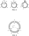
- Figure 4 shows a cross-sectional view of a smoking article comprising a filter element according to the present disclosure, through the location of the perforation 8 and slot 13.
- the smoking article according to the present invention is substantially similar in structure to that shown in Figures 1 to 3 , with the exception that the plug wrap provided is substantially air permeable or porous.
- plug wrap papers having porosities ranging from about 1300 CU to 24000 CU can be used in the smoking article of the present invention.
- the user can rotate the mouth end filter segment 5 to vary the relative locations of the slot 13 and perforation 8 and vary the ventilation for the filter component 3 varying air mixture received by a user when the tobacco rod 2 is lit.
- the plug wrap 40 is porous, therefore allowing at least some airflow through the filter at all times, irrespective of the alignment of the slot 13 and perforation 8. Since airflow always passes through the filter element 3, the variation of air dilution obtained by the relative positions of the slot 13 and perforation 8 is smaller than in the case of Figure 3 .
- this improves control of the user who is able to steadily vary the smoke intensity, i.e. the tar delivery of the smoking article between two ventilated states.
- the filter of the invention provides pressure drops of below 130 mmH2O and preferably below 120 mmH2O in any respective position of the slot 13 and perforation 8. This particularly reduces resistance to drawing smoke through the filter element 3 whilst a user tuned the filter to obtain high tar delivery states.
- any plurality of perforations 8 and/or slots 13 could be provided to achieve the same function of varying the ventilation level in the filter component 3, the common principle of ventilation variation remaining identical and based on alignment/misalignment of said perforations 8 and slot 13 upon rotation of the mouth end segment 5 of the filter with respect to the tobacco end segment 6.
- the perforations 8 are of equal length and can vary from 2.00 mm to 4.5 mm, for example.
- FIGs 6A and 6B shows the variation of the airflow through the filter component 3 represented in Figure 7 , using relatively small perforations 8, e.g. 2.5 mm and matching slots 13 ( Figure 6A ) and relatively large perforations 8, e.g. 4.0 mm and matching slots 13 ( Figure 6B ). Since the plug wrap 40 is porous, airflow always passes through the filter component 3, resulting in a relatively weak but permanent airflow in the case of relatively small perforations 8 and matching slots 13 ( Figure 6A ), and a relatively strong, permanent airflow in the case of relatively large perforations 8 and matching slots 13 ( Figure 6B ).
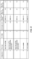
- Figure 8 is a table reproducing minimum and maximum tar deliveries obtained for five different smoking articles according to the invention, with different filter structures (dual charcoal acetate or mono-acetate filters), different plug wrap porosities and different perforations sizes.
- the tar deliveries reproduced in that table were obtained under standard ISO smoking regime, following ISO standards for testing smoking articles (ISO 3308, ISO 4387).
- filter plug-forming material that may be a material such as cellulose acetate tow in a conventional and well-known manner in the industry of cigarette filter making.
- a continuous filter rod is hereby obtained. This continuous rod is then surrounded with a porous plug wrap 40 to hold the acetate tow in shape and segmented to produce individual filter components 3.
- filter components 3 are then loaded into a conventional smoking article maker which is equipped with a processing module to assemble filter components 3 and tobacco rods 2 to form cigarettes 1.
- the filter components 3 are then cut transversally to form two rotatable interconnected segments 5, 6.
- Perforations 8 are formed in the filter components 3 by laser or blade cutting.
- the pre-perforated tipping paper 9 may be used.
- the tipping paper 9 may be perforated and cut or preferably pre-cut to define separation line 12 between bands 10, 11 of the tipping paper 9 and then supplied and wrapped around the filter component 3 to connect it with the tobacco rod 2 to form a cigarette product.
- the filter components 3 are submitted to a laser or blade cut to form simultaneously perforations 8 in the tobacco end filter segment 6 and corresponding slots 13 in the tipping paper 9.
- the mouth end filter segment 5 is then twisted to misalign perforations 8 and slots 13 of the filters and thereby set the cigarette products 1 at the lowest level of ventilation of the filter components 3.
- the finished cigarette products are then gathered to form a bundle which is then packed for sale.
Landscapes
- Chemical & Material Sciences (AREA)
- Inorganic Chemistry (AREA)
- Engineering & Computer Science (AREA)
- Materials Engineering (AREA)
- Cigarettes, Filters, And Manufacturing Of Filters (AREA)
Description
- The present invention relates to a filter element for a smoking article. In particular, the present invention relates to a filter element which enables a user to vary the ratio of tobacco smoke to air inhaled by providing a mechanism by varying the pressure drop across the filter.
- Filter elements for smoking articles are, of course, well known. It is also well known to provide filter elements that have means for varying the ratio of tobacco smoke to air inhaled by a user by providing a mechanism to the user to vary the pressure drop across the filter. Examples of such configurations are shown in
US4646763 ,US4649944 ,US4570649 orWO 2013/079645 , for example. Such configurations allow for variations of the ventilation level of the filter, therefore of the smoke intensity and tar delivery of the smoking articles, between a maximum tar delivery in a first state and a second tar delivery in a second state. - Whilst such known filter elements have some benefits in that they allow a user control over the smoke intensity, they also have a number of disadvantages. In particular, the level of control of the user is restricted because the variation of air dilution is relatively limited. The level of control is particularly restricted if a user wants to vary the filter between two ventilated states of the smoking articles, i.e. two reduced tar delivery states.
- The present invention seeks to provide a filter element which improves control of the smoke intensity by a user, enabling the user to vary the pressure drop across the filter between reduced tar delivery states whilst still ensuring that a cost effective filter element is provided.
- To that aim, the present invention provides a filter element for a smoking article, the filter element comprising: at least one plug of filter material surrounded by a substantially air permeable plug wrap, wherein the plug of filter material comprises at least two segments being longitudinally aligned and rotatably mounted about a common longitudinal axis, at least one of the segments comprising at least one perforation formed in the substantially air permeable plug wrap; and a wrapping material surrounding at least one portion of the substantially air permeable plug wrap, the wrapping material comprising a first part attached to a first of the two segments of the plug of filter material and a second part attached to the second segment of the plug of filter material, and comprising at least one aperture formed therein, the first and second parts of the wrapping material and first and second segments of the plug of filter material being arranged such that the respective at least one perforation of the substantially air permeable plug wrap and the at least one aperture of the wrapping material can be superimposed upon rotation of one of the segments of the plug of filter material about the common longitudinal axis to vary the filter ventilation; wherein each of the at least one perforation has a first length and each of the at least one aperture has a second length different to the first length.
- The filter element according to the present invention therefore includes a combination of aligning slots, respectively referred to as perforations and apertures, and a substantially air permeable or porous plug wrap for allowing air flow into the filter. Importantly, using this combination of aligning slots and porous plug wrap allows for a relatively small variation of air dilution, which results in an improved stability and fine tuning of the variable filter product. Advantageously, this enables the manufacture of cigarettes having variable taste strength and tar deliveries, by providing a filter element adjustable between two ventilated cigarette configurations.
- The at least one perforation may be formed in the second segment of the filter material and the at least one aperture may be formed in the second part of the wrapping material.
- Preferably, each of the at least one perforation has a first length and each of the at least one aperture has a second length. In other words, each of the perforations have the same length, while each of the apertures also have the same length (which is different from the length of the apertures), which facilitates manufacturing of the filter element.
- Preferably, at least one of the segments of the filter material comprises at least three perforations spaced equidistally from each other. For example, there may be three perforations of equal length located in the same plane around a circumference of the plug wrap, at approximately 120 degrees from each other.
- A further aspect of the invention relates to a smoking article comprising a filter element as previously described. Such a smoking article would typically include a tobacco rod connected to an end of the filter by the wrapping material which overlaps said end of the filter element and one end of the tobacco rod.
- Preferably, the second part of the wrapping material comprising the aperture surrounds a segment of the plug of filter material including the perforation and at least part of a segment of the plug of filter material free from the at least one perforation.
- The first and second parts of the wrapping material may be separated by a circumferential slit around the filter plug, while the first and second segments of the plug of filter material may be separated by a circumferential cut in a second plane perpendicular to the common longitudinal axis, and wherein the circumferential slit is located in the second plane. As such, the circumferential slit in the wrapping material corresponds to a circumferential cut in the plug of filter material, both being located in the same plane. It will be appreciated that the terms "slit" and "cut" convey the same meaning, however the different terms, referring to the wrapping and filter materials, are respectively used for the sake of clarity.
- An example of the present invention, together with a method of manufacture thereof, will now be described with reference to the accompanying drawings, in which:
-
Figures 1 and 2 show a conventional variable flow filter for a smoking article; -
Figure 3 is a cross-sectional view of a smoking article comprising a conventional variable flow filter for a smoking article; -
Figures 4 and 5 are cross-sectional views of smoking articles comprising a filter element according to the present disclosure; -
Figures 6A and 6B show sequences of alignment corresponding to relative positions of perforations in the porous plug wrap and slots in the tipping paper to control the amount of air that can be drawn through the combination of aligning slots and perforations; -
Figure 7 shows another filter element according to the present invention; and -
Figure 8 is a table reproducing minimum and maximum tar deliveries obtained for five different smoking articles according to the invention. - Referring to
Figure 1 , afilter cigarette 1 comprises atobacco rod 2 and afilter component 3. Thefilter component 3 is configured to allow adjustment of the filter ventilation by a user to adjust the taste strength of thecigarette 1. Thefilter component 3 comprises a plug of filter material such as cellulose acetate having aplug wrap 4 extending over its outer surface. In the known priorart filter components 3, theplug wrap 4 is substantially air impermeable. - The
filter component 3 is divided into a mouthend filter segment 5 and a tobaccoend filter segment 6, by a circumferential transverse cut 7, which is perpendicular to the longitudinal axis of thecigarette 1. The cut 7 is only partial throughout the diameter of thefilter plug 4 so as to leave a central connecting member of filter material between the twosegments segments - At least one slit, also referred to as a
perforation 8, is formed into theplug wrap 4 in the tobaccoend filter segment 6. Thisperforation 8 allows air to be drawn in through theplug wrap 4 and into the core of thefilter component 3. - To assemble the
filter component 3 to thetobacco rod 2, a suitable wrapping material such as tippingpaper 9 is provided and wrapped over theplug wrap 4 andfilter segments paper 9 is comprised of twobands cut line 12. Afirst band 10 of thetipping paper 9 is attached, usually by gluing, to the mouthend filter segment 5 of thecigarette 1 and extends over the cut 7 between the twofilter segments second filter segment 6 and theperforation 8 without being attached to thesecond segment 6. Thisfirst tipping band 10 comprises at least onetransverse slot 13 which is positioned so that it can be aligned over theperforation 8 in thesecond filter segment 6. Asecond tipping band 11 of thetipping paper 9 is attached, usually by gluing, on the remaining part of thetobacco end segment 6 not covered byband 10 and thetobacco rod 2 to attach thefilter component 3 to thetobacco rod 2. -
Figure 2 showsFigure 1 when assembled with theslot 13 offirst band 10 oftipping paper 9 aligned over theperforation 8. - Such configuration of the
filter component 3 and tippingpaper 9 makes the mouthend filter segment 5 capable of rotation around the longitudinal axis of thecigarette 1 relative to the tobaccoend filter segment 6 connected to thetobacco rod 2. This varies the respective positions of theperforation 8 in the tobaccoend filter segment 6 and theslot 13 in thefirst tipping band 10 as shown inFigure 3 in order to adjust the ventilation of thefilter component 3, and hence the strength of thecigarette 1. -
Figure 3 shows a cross-sectional view of thefilter component 3 through the location of theperforation 8 andslot 13. From this it can be seen that relative rotation of the mouthend filter segment 5 with respect to tobaccoend filter segment 6 in either direction can adjust the relative positions of theslot 13 andperforation 8 to control the amount of air that can be drawn through the combination of theslot 13 andperforation 8 and into thefilter component 3 when thecigarette 1 is being smoked. - In use, the user can rotate the mouth
end filter segment 5 to vary the relative locations of theslot 13 andperforation 8 and vary the ventilation for thefilter component 3 varying air mixture received by a user when thetobacco rod 2 is lit. Importantly, with theconventional filter component 3, airflow can only be drawn through the combination of theslot 13 andperforation 8 and into thefilter component 3, since theplug wrap 4 in the known configurations is substantially air impermeable. -
Figure 4 shows a cross-sectional view of a smoking article comprising a filter element according to the present disclosure, through the location of theperforation 8 andslot 13. The smoking article according to the present invention is substantially similar in structure to that shown inFigures 1 to 3 , with the exception that the plug wrap provided is substantially air permeable or porous. For example, plug wrap papers having porosities ranging from about 1300 CU to 24000 CU can be used in the smoking article of the present invention. As inFigure 3 , it can be seen that relative rotation of the mouthend filter segment 5 with respect to tobaccoend filter segment 6 in either direction can adjust the relative positions of theslot 13 andperforation 8 to control the amount of air that can be drawn through the combination of theslot 13 andperforation 8 and into thefilter component 3 when thecigarette 1 is being smoked. - In use, the user can rotate the mouth
end filter segment 5 to vary the relative locations of theslot 13 andperforation 8 and vary the ventilation for thefilter component 3 varying air mixture received by a user when thetobacco rod 2 is lit. Unlike in the known case ofFigure 3 , however, theplug wrap 40 is porous, therefore allowing at least some airflow through the filter at all times, irrespective of the alignment of theslot 13 andperforation 8. Since airflow always passes through thefilter element 3, the variation of air dilution obtained by the relative positions of theslot 13 andperforation 8 is smaller than in the case ofFigure 3 . Advantageously, this improves control of the user who is able to steadily vary the smoke intensity, i.e. the tar delivery of the smoking article between two ventilated states. It is thereby possible to vary for example the tar delivery between 0.1 mg and 8.0 mg for example. Another advantage provided by the filter of the invention is that it is possible to obtain relatively high tar delivery states (in particular above 7 mg of tar) without the need to have high pressure drop values of thesmoking article 1, in particular pressure drop values of 130 mmH2O and above. The filter and smoking article of the invention provide pressure drops of below 130 mmH2O and preferably below 120 mmH2O in any respective position of theslot 13 andperforation 8. This particularly reduces resistance to drawing smoke through thefilter element 3 whilst a user tuned the filter to obtain high tar delivery states. - It will be understood that any plurality of
perforations 8 and/orslots 13 could be provided to achieve the same function of varying the ventilation level in thefilter component 3, the common principle of ventilation variation remaining identical and based on alignment/misalignment of saidperforations 8 and slot 13 upon rotation of themouth end segment 5 of the filter with respect to thetobacco end segment 6. - Preferably, the
perforations 8 are of equal length and can vary from 2.00 mm to 4.5 mm, for example. In a preferred embodiment, there are threeperforations 8 formed into theplug wrap 40, situated on the same plane and located at an angle θ of approximately 120 degrees from each other, as shown inFigure 5 . -
Figures 6A and 6B shows the variation of the airflow through thefilter component 3 represented inFigure 7 , using relativelysmall perforations 8, e.g. 2.5 mm and matching slots 13 (Figure 6A ) and relativelylarge perforations 8, e.g. 4.0 mm and matching slots 13 (Figure 6B ). Since theplug wrap 40 is porous, airflow always passes through thefilter component 3, resulting in a relatively weak but permanent airflow in the case of relativelysmall perforations 8 and matching slots 13 (Figure 6A ), and a relatively strong, permanent airflow in the case of relativelylarge perforations 8 and matching slots 13 (Figure 6B ). -
Figure 8 is a table reproducing minimum and maximum tar deliveries obtained for five different smoking articles according to the invention, with different filter structures (dual charcoal acetate or mono-acetate filters), different plug wrap porosities and different perforations sizes. The tar deliveries reproduced in that table were obtained under standard ISO smoking regime, following ISO standards for testing smoking articles (ISO 3308, ISO 4387). - An example method of manufacturing the filter according to the present disclosure will now be described.
- In a first stage there is provided filter plug-forming material that may be a material such as cellulose acetate tow in a conventional and well-known manner in the industry of cigarette filter making. A continuous filter rod is hereby obtained. This continuous rod is then surrounded with a
porous plug wrap 40 to hold the acetate tow in shape and segmented to produceindividual filter components 3. -
Individual filter components 3 are then loaded into a conventional smoking article maker which is equipped with a processing module to assemblefilter components 3 andtobacco rods 2 to formcigarettes 1. Thefilter components 3 are then cut transversally to form two rotatableinterconnected segments Perforations 8 are formed in thefilter components 3 by laser or blade cutting. - In some embodiments, the
pre-perforated tipping paper 9 may be used. Alternatively, the tippingpaper 9 may be perforated and cut or preferably pre-cut to defineseparation line 12 betweenbands paper 9 and then supplied and wrapped around thefilter component 3 to connect it with thetobacco rod 2 to form a cigarette product. Thefilter components 3 are submitted to a laser or blade cut to form simultaneously perforations 8 in the tobaccoend filter segment 6 andcorresponding slots 13 in thetipping paper 9. Finally, the mouthend filter segment 5 is then twisted to misalignperforations 8 andslots 13 of the filters and thereby set thecigarette products 1 at the lowest level of ventilation of thefilter components 3. The finished cigarette products are then gathered to form a bundle which is then packed for sale.
Claims (11)
- A filter element (3) for a smoking article, the filter element (3) comprising:at least one plug of filter material surrounded by a substantially air permeable plug wrap (40), wherein the plug of filter material comprises at least two segments (5, 6) being longitudinally aligned and rotatably mounted about a common longitudinal axis, at least one of the segments (5, 6) comprising at least one perforation (8) formed in the substantially air permeable plug wrap (40); anda wrapping material (9) surrounding at least one portion of the substantially air permeable plug wrap (40), the wrapping material (9) comprising a first part (10) attached to a first (5) of the two segments of the plug of filter material and a second part (11) attached to the second segment (6) of the plug of filter material, and comprising at least one aperture (13) formed therein,the first and second parts (10, 11) of the wrapping material (9) and first and second segments (5, 6) of the plug of filter material being arranged such that the respective at least one perforation (8) of the substantially air permeable plug wrap (40) and the at least one aperture (13) of the wrapping material (9) can be superimposed upon rotation of one of the segments (5, 6) of the plug of filter material about the common longitudinal axis to vary the filter ventilation; characterized in that each of the at least one perforation (8) has a first length and each of the at least one aperture (13) has a second length different to the first length.
- A filter element (3) according to claim 1, wherein the at least one perforation (8) is formed in the second segment (6) of the filter material and the at least one aperture (13) is formed in the second part (11) of the wrapping material (9).
- A filter element (3) according to any one of the preceding claims, wherein each of the at least one perforation (8) and each of the at least one aperture (13) is located in a first plane perpendicular to the common longitudinal axis.
- A filter element according to claim 3, wherein the at least one of the segments (5, 6) of the filter material comprises at least three perforations (8) spaced equidistally from each other.
- A filter element according to any preceding claim, further comprising at least one second plug of filter material comprising an adsorbent material, preferably activated charcoal.
- A filter element according to any preceding claim, wherein the plug wrap porosity is comprised between about 1300 CU and about 24000 CU.
- A smoking article (1) comprising a filter element (3) according to any of claims 1 to 6 and a tobacco rod (2) connected to an end of the filter element (3) by the wrapping material (9) overlapping said end of the filter element (3) and one end of the tobacco rod (2).
- A smoking article according to claim 7, having a maximum pressure drop of below 130 mmH2O.
- A smoking article (1) according to claim 7 or claim 8, wherein the second part of the wrapping material (11) comprising the aperture (13) surrounds a segment (6) of the plug of filter material including the perforation (8) and at least part of a segment (6) of the plug of filter material free from the at least one perforation (8).
- A smoking article (1) according to any of claims 8 to 9, wherein the first and second parts (10, 11) of the wrapping material (9) are separated by a circumferential slit (12) around the filter plug.
- A smoking article according to claim 10, wherein the first and second segments (5, 6) of the plug of filter material are separated by a circumferential cut (7) in a second plane perpendicular to the common longitudinal axis, and wherein the circumferential slit (12) is located in the second plane.
Priority Applications (1)
| Application Number | Priority Date | Filing Date | Title |
|---|---|---|---|
| PL15704818T PL3116333T3 (en) | 2014-03-11 | 2015-02-18 | Filter element for a smoking article |
Applications Claiming Priority (2)
| Application Number | Priority Date | Filing Date | Title |
|---|---|---|---|
| EP14158737 | 2014-03-11 | ||
| PCT/EP2015/053418 WO2015135723A1 (en) | 2014-03-11 | 2015-02-18 | Filter element for a smoking article |
Publications (2)
| Publication Number | Publication Date |
|---|---|
| EP3116333A1 EP3116333A1 (en) | 2017-01-18 |
| EP3116333B1 true EP3116333B1 (en) | 2018-12-19 |
Family
ID=50239489
Family Applications (1)
| Application Number | Title | Priority Date | Filing Date |
|---|---|---|---|
| EP15704818.2A Active EP3116333B1 (en) | 2014-03-11 | 2015-02-18 | Filter element for a smoking article |
Country Status (8)
| Country | Link |
|---|---|
| EP (1) | EP3116333B1 (en) |
| JP (1) | JP2017507660A (en) |
| KR (1) | KR20160134732A (en) |
| EA (1) | EA032253B1 (en) |
| ES (1) | ES2706491T3 (en) |
| PL (1) | PL3116333T3 (en) |
| TR (1) | TR201900291T4 (en) |
| WO (1) | WO2015135723A1 (en) |
Cited By (1)
| Publication number | Priority date | Publication date | Assignee | Title |
|---|---|---|---|---|
| EP4118981A4 (en) * | 2021-05-31 | 2023-08-23 | China Tobacco Yunnan Industrial Co., Ltd | Heating cigarette with adjustable tube wall air permeability and air permeation position, and adjustment method |
Families Citing this family (3)
| Publication number | Priority date | Publication date | Assignee | Title |
|---|---|---|---|---|
| CN110392533B (en) | 2017-04-03 | 2022-04-08 | 菲利普莫里斯生产公司 | Smoking article mouthpiece configured to receive an insertion unit |
| JP7096354B2 (en) * | 2019-04-29 | 2022-07-05 | 雲南中煙工業有限責任公司 | Low cut-off heated non-burning tobacco tobacco stick |
| WO2025126308A1 (en) * | 2023-12-12 | 2025-06-19 | 日本たばこ産業株式会社 | Flavor-generating article |
Family Cites Families (8)
| Publication number | Priority date | Publication date | Assignee | Title |
|---|---|---|---|---|
| US4649944A (en) * | 1982-09-30 | 1987-03-17 | Philip Morris Incorporated | Filter cigarette |
| US4570649A (en) * | 1982-09-30 | 1986-02-18 | Philip Morris Incorporated | Filter cigarette |
| US4646763A (en) * | 1985-11-19 | 1987-03-03 | Philip Morris Incorporated | Adjustable filter cigarette |
| US4687009A (en) * | 1986-02-24 | 1987-08-18 | Philip Morris Incorporated | Adjustable filter cigarette and method of manufacture thereof |
| JP3181248B2 (en) * | 1997-10-06 | 2001-07-03 | 日本たばこ産業株式会社 | Cigarette with filter and filter for cigarette |
| EP2368448A1 (en) * | 2010-03-26 | 2011-09-28 | Philip Morris Products S.A. | Smoking article with variable ventilation |
| GB201116866D0 (en) * | 2011-09-29 | 2011-11-09 | British American Tobacco Co | Smoking articles |
| AR089183A1 (en) * | 2011-11-30 | 2014-08-06 | Philip Morris Products Sa | ARTICLE TO SMOKE WITH A VENTILATED NOZZLE THAT INCLUDES FIRST AND SECOND ROADS OF AIR FLOW |
-
2015
- 2015-02-18 TR TR2019/00291T patent/TR201900291T4/en unknown
- 2015-02-18 PL PL15704818T patent/PL3116333T3/en unknown
- 2015-02-18 EA EA201691601A patent/EA032253B1/en not_active IP Right Cessation
- 2015-02-18 EP EP15704818.2A patent/EP3116333B1/en active Active
- 2015-02-18 ES ES15704818T patent/ES2706491T3/en active Active
- 2015-02-18 WO PCT/EP2015/053418 patent/WO2015135723A1/en not_active Ceased
- 2015-02-18 JP JP2016556290A patent/JP2017507660A/en active Pending
- 2015-02-18 KR KR1020167028283A patent/KR20160134732A/en not_active Ceased
Non-Patent Citations (1)
| Title |
|---|
| None * |
Cited By (1)
| Publication number | Priority date | Publication date | Assignee | Title |
|---|---|---|---|---|
| EP4118981A4 (en) * | 2021-05-31 | 2023-08-23 | China Tobacco Yunnan Industrial Co., Ltd | Heating cigarette with adjustable tube wall air permeability and air permeation position, and adjustment method |
Also Published As
| Publication number | Publication date |
|---|---|
| KR20160134732A (en) | 2016-11-23 |
| JP2017507660A (en) | 2017-03-23 |
| EA201691601A1 (en) | 2017-03-31 |
| PL3116333T3 (en) | 2019-06-28 |
| WO2015135723A1 (en) | 2015-09-17 |
| EA032253B1 (en) | 2019-04-30 |
| ES2706491T3 (en) | 2019-03-29 |
| EP3116333A1 (en) | 2017-01-18 |
| TR201900291T4 (en) | 2019-02-21 |
Similar Documents
| Publication | Publication Date | Title |
|---|---|---|
| RU2668750C1 (en) | Smoking article, filter and method of manufacturing of smoking article | |
| EP2785207B1 (en) | Smoking article with a ventilated mouthpiece comprising first and second airflow pathways | |
| EP3027071B1 (en) | Filter element for a smoking article | |
| EP0908110B1 (en) | Filter-tipped cigarette and filter for a cigarette | |
| EP2033531A1 (en) | Smoking article with variable ventilation | |
| EP3102055B1 (en) | Multi-segment filter tube | |
| EP2661184B1 (en) | Smoking article | |
| EP2352398B1 (en) | Filter for a smoking article | |
| WO2015135723A1 (en) | Filter element for a smoking article | |
| EP3242569B1 (en) | Variable pressure drop smoking article | |
| WO2019081913A1 (en) | A smoking article or an aerosol generating product | |
| EP2967132B1 (en) | Filter cigarette with variable ventilation | |
| HK1228209A1 (en) | Multi-segment filter tube | |
| HK1228209B (en) | Multi-segment filter tube | |
| HK1157150A (en) | Filter for a smoking article | |
| HK1197978A (en) | Smoking article with a ventilated mouthpiece comprising first and second airflow pathways |
Legal Events
| Date | Code | Title | Description |
|---|---|---|---|
| STAA | Information on the status of an ep patent application or granted ep patent |
Free format text: STATUS: THE INTERNATIONAL PUBLICATION HAS BEEN MADE |
|
| PUAI | Public reference made under article 153(3) epc to a published international application that has entered the european phase |
Free format text: ORIGINAL CODE: 0009012 |
|
| STAA | Information on the status of an ep patent application or granted ep patent |
Free format text: STATUS: REQUEST FOR EXAMINATION WAS MADE |
|
| 17P | Request for examination filed |
Effective date: 20160907 |
|
| AK | Designated contracting states |
Kind code of ref document: A1 Designated state(s): AL AT BE BG CH CY CZ DE DK EE ES FI FR GB GR HR HU IE IS IT LI LT LU LV MC MK MT NL NO PL PT RO RS SE SI SK SM TR |
|
| AX | Request for extension of the european patent |
Extension state: BA ME |
|
| RIN1 | Information on inventor provided before grant (corrected) |
Inventor name: OKUNO, HIROSHI Inventor name: NAGAI, NOBUO |
|
| DAX | Request for extension of the european patent (deleted) | ||
| STAA | Information on the status of an ep patent application or granted ep patent |
Free format text: STATUS: EXAMINATION IS IN PROGRESS |
|
| 17Q | First examination report despatched |
Effective date: 20171124 |
|
| GRAP | Despatch of communication of intention to grant a patent |
Free format text: ORIGINAL CODE: EPIDOSNIGR1 |
|
| STAA | Information on the status of an ep patent application or granted ep patent |
Free format text: STATUS: GRANT OF PATENT IS INTENDED |
|
| INTG | Intention to grant announced |
Effective date: 20180713 |
|
| GRAS | Grant fee paid |
Free format text: ORIGINAL CODE: EPIDOSNIGR3 |
|
| GRAA | (expected) grant |
Free format text: ORIGINAL CODE: 0009210 |
|
| STAA | Information on the status of an ep patent application or granted ep patent |
Free format text: STATUS: THE PATENT HAS BEEN GRANTED |
|
| AK | Designated contracting states |
Kind code of ref document: B1 Designated state(s): AL AT BE BG CH CY CZ DE DK EE ES FI FR GB GR HR HU IE IS IT LI LT LU LV MC MK MT NL NO PL PT RO RS SE SI SK SM TR |
|
| REG | Reference to a national code |
Ref country code: GB Ref legal event code: FG4D |
|
| REG | Reference to a national code |
Ref country code: CH Ref legal event code: EP Ref country code: CH Ref legal event code: NV Representative=s name: VALIPAT S.A. GEVERS SA, CH |
|
| REG | Reference to a national code |
Ref country code: IE Ref legal event code: FG4D |
|
| REG | Reference to a national code |
Ref country code: DE Ref legal event code: R096 Ref document number: 602015021818 Country of ref document: DE |
|
| REG | Reference to a national code |
Ref country code: AT Ref legal event code: REF Ref document number: 1077733 Country of ref document: AT Kind code of ref document: T Effective date: 20190115 |
|
| REG | Reference to a national code |
Ref country code: RO Ref legal event code: EPE |
|
| REG | Reference to a national code |
Ref country code: NL Ref legal event code: FP |
|
| REG | Reference to a national code |
Ref country code: ES Ref legal event code: FG2A Ref document number: 2706491 Country of ref document: ES Kind code of ref document: T3 Effective date: 20190329 Ref country code: CH Ref legal event code: PCAR Free format text: NEW ADDRESS: RUE DES NOYERS 11, 2000 NEUCHATEL (CH) |
|
| REG | Reference to a national code |
Ref country code: GR Ref legal event code: EP Ref document number: 20190400203 Country of ref document: GR Effective date: 20190422 |
|
| PG25 | Lapsed in a contracting state [announced via postgrant information from national office to epo] |
Ref country code: BG Free format text: LAPSE BECAUSE OF FAILURE TO SUBMIT A TRANSLATION OF THE DESCRIPTION OR TO PAY THE FEE WITHIN THE PRESCRIBED TIME-LIMIT Effective date: 20190319 Ref country code: FI Free format text: LAPSE BECAUSE OF FAILURE TO SUBMIT A TRANSLATION OF THE DESCRIPTION OR TO PAY THE FEE WITHIN THE PRESCRIBED TIME-LIMIT Effective date: 20181219 Ref country code: LT Free format text: LAPSE BECAUSE OF FAILURE TO SUBMIT A TRANSLATION OF THE DESCRIPTION OR TO PAY THE FEE WITHIN THE PRESCRIBED TIME-LIMIT Effective date: 20181219 Ref country code: LV Free format text: LAPSE BECAUSE OF FAILURE TO SUBMIT A TRANSLATION OF THE DESCRIPTION OR TO PAY THE FEE WITHIN THE PRESCRIBED TIME-LIMIT Effective date: 20181219 Ref country code: HR Free format text: LAPSE BECAUSE OF FAILURE TO SUBMIT A TRANSLATION OF THE DESCRIPTION OR TO PAY THE FEE WITHIN THE PRESCRIBED TIME-LIMIT Effective date: 20181219 Ref country code: NO Free format text: LAPSE BECAUSE OF FAILURE TO SUBMIT A TRANSLATION OF THE DESCRIPTION OR TO PAY THE FEE WITHIN THE PRESCRIBED TIME-LIMIT Effective date: 20190319 |
|
| REG | Reference to a national code |
Ref country code: LT Ref legal event code: MG4D |
|
| REG | Reference to a national code |
Ref country code: AT Ref legal event code: MK05 Ref document number: 1077733 Country of ref document: AT Kind code of ref document: T Effective date: 20181219 |
|
| PG25 | Lapsed in a contracting state [announced via postgrant information from national office to epo] |
Ref country code: SE Free format text: LAPSE BECAUSE OF FAILURE TO SUBMIT A TRANSLATION OF THE DESCRIPTION OR TO PAY THE FEE WITHIN THE PRESCRIBED TIME-LIMIT Effective date: 20181219 Ref country code: RS Free format text: LAPSE BECAUSE OF FAILURE TO SUBMIT A TRANSLATION OF THE DESCRIPTION OR TO PAY THE FEE WITHIN THE PRESCRIBED TIME-LIMIT Effective date: 20181219 Ref country code: AL Free format text: LAPSE BECAUSE OF FAILURE TO SUBMIT A TRANSLATION OF THE DESCRIPTION OR TO PAY THE FEE WITHIN THE PRESCRIBED TIME-LIMIT Effective date: 20181219 |
|
| PG25 | Lapsed in a contracting state [announced via postgrant information from national office to epo] |
Ref country code: CZ Free format text: LAPSE BECAUSE OF FAILURE TO SUBMIT A TRANSLATION OF THE DESCRIPTION OR TO PAY THE FEE WITHIN THE PRESCRIBED TIME-LIMIT Effective date: 20181219 Ref country code: PT Free format text: LAPSE BECAUSE OF FAILURE TO SUBMIT A TRANSLATION OF THE DESCRIPTION OR TO PAY THE FEE WITHIN THE PRESCRIBED TIME-LIMIT Effective date: 20190419 |
|
| PG25 | Lapsed in a contracting state [announced via postgrant information from national office to epo] |
Ref country code: SK Free format text: LAPSE BECAUSE OF FAILURE TO SUBMIT A TRANSLATION OF THE DESCRIPTION OR TO PAY THE FEE WITHIN THE PRESCRIBED TIME-LIMIT Effective date: 20181219 Ref country code: IS Free format text: LAPSE BECAUSE OF FAILURE TO SUBMIT A TRANSLATION OF THE DESCRIPTION OR TO PAY THE FEE WITHIN THE PRESCRIBED TIME-LIMIT Effective date: 20190419 Ref country code: SM Free format text: LAPSE BECAUSE OF FAILURE TO SUBMIT A TRANSLATION OF THE DESCRIPTION OR TO PAY THE FEE WITHIN THE PRESCRIBED TIME-LIMIT Effective date: 20181219 Ref country code: EE Free format text: LAPSE BECAUSE OF FAILURE TO SUBMIT A TRANSLATION OF THE DESCRIPTION OR TO PAY THE FEE WITHIN THE PRESCRIBED TIME-LIMIT Effective date: 20181219 |
|
| REG | Reference to a national code |
Ref country code: DE Ref legal event code: R097 Ref document number: 602015021818 Country of ref document: DE |
|
| PLBE | No opposition filed within time limit |
Free format text: ORIGINAL CODE: 0009261 |
|
| STAA | Information on the status of an ep patent application or granted ep patent |
Free format text: STATUS: NO OPPOSITION FILED WITHIN TIME LIMIT |
|
| PG25 | Lapsed in a contracting state [announced via postgrant information from national office to epo] |
Ref country code: AT Free format text: LAPSE BECAUSE OF FAILURE TO SUBMIT A TRANSLATION OF THE DESCRIPTION OR TO PAY THE FEE WITHIN THE PRESCRIBED TIME-LIMIT Effective date: 20181219 Ref country code: MC Free format text: LAPSE BECAUSE OF FAILURE TO SUBMIT A TRANSLATION OF THE DESCRIPTION OR TO PAY THE FEE WITHIN THE PRESCRIBED TIME-LIMIT Effective date: 20181219 Ref country code: LU Free format text: LAPSE BECAUSE OF NON-PAYMENT OF DUE FEES Effective date: 20190218 Ref country code: DK Free format text: LAPSE BECAUSE OF FAILURE TO SUBMIT A TRANSLATION OF THE DESCRIPTION OR TO PAY THE FEE WITHIN THE PRESCRIBED TIME-LIMIT Effective date: 20181219 |
|
| REG | Reference to a national code |
Ref country code: BE Ref legal event code: MM Effective date: 20190228 |
|
| 26N | No opposition filed |
Effective date: 20190920 |
|
| PG25 | Lapsed in a contracting state [announced via postgrant information from national office to epo] |
Ref country code: BE Free format text: LAPSE BECAUSE OF NON-PAYMENT OF DUE FEES Effective date: 20190228 Ref country code: SI Free format text: LAPSE BECAUSE OF FAILURE TO SUBMIT A TRANSLATION OF THE DESCRIPTION OR TO PAY THE FEE WITHIN THE PRESCRIBED TIME-LIMIT Effective date: 20181219 |
|
| PG25 | Lapsed in a contracting state [announced via postgrant information from national office to epo] |
Ref country code: MT Free format text: LAPSE BECAUSE OF NON-PAYMENT OF DUE FEES Effective date: 20190218 |
|
| PG25 | Lapsed in a contracting state [announced via postgrant information from national office to epo] |
Ref country code: CY Free format text: LAPSE BECAUSE OF FAILURE TO SUBMIT A TRANSLATION OF THE DESCRIPTION OR TO PAY THE FEE WITHIN THE PRESCRIBED TIME-LIMIT Effective date: 20181219 |
|
| PG25 | Lapsed in a contracting state [announced via postgrant information from national office to epo] |
Ref country code: HU Free format text: LAPSE BECAUSE OF FAILURE TO SUBMIT A TRANSLATION OF THE DESCRIPTION OR TO PAY THE FEE WITHIN THE PRESCRIBED TIME-LIMIT; INVALID AB INITIO Effective date: 20150218 |
|
| PGFP | Annual fee paid to national office [announced via postgrant information from national office to epo] |
Ref country code: IE Payment date: 20220216 Year of fee payment: 8 Ref country code: CH Payment date: 20220216 Year of fee payment: 8 |
|
| PGFP | Annual fee paid to national office [announced via postgrant information from national office to epo] |
Ref country code: TR Payment date: 20220216 Year of fee payment: 8 Ref country code: RO Payment date: 20220210 Year of fee payment: 8 Ref country code: PL Payment date: 20220210 Year of fee payment: 8 Ref country code: NL Payment date: 20220216 Year of fee payment: 8 Ref country code: GR Payment date: 20220221 Year of fee payment: 8 |
|
| PG25 | Lapsed in a contracting state [announced via postgrant information from national office to epo] |
Ref country code: MK Free format text: LAPSE BECAUSE OF FAILURE TO SUBMIT A TRANSLATION OF THE DESCRIPTION OR TO PAY THE FEE WITHIN THE PRESCRIBED TIME-LIMIT Effective date: 20181219 |
|
| PGFP | Annual fee paid to national office [announced via postgrant information from national office to epo] |
Ref country code: ES Payment date: 20220426 Year of fee payment: 8 |
|
| P01 | Opt-out of the competence of the unified patent court (upc) registered |
Effective date: 20230522 |
|
| REG | Reference to a national code |
Ref country code: CH Ref legal event code: PL |
|
| REG | Reference to a national code |
Ref country code: NL Ref legal event code: MM Effective date: 20230301 |
|
| PG25 | Lapsed in a contracting state [announced via postgrant information from national office to epo] |
Ref country code: RO Free format text: LAPSE BECAUSE OF NON-PAYMENT OF DUE FEES Effective date: 20230218 Ref country code: LI Free format text: LAPSE BECAUSE OF NON-PAYMENT OF DUE FEES Effective date: 20230228 Ref country code: CH Free format text: LAPSE BECAUSE OF NON-PAYMENT OF DUE FEES Effective date: 20230228 |
|
| PG25 | Lapsed in a contracting state [announced via postgrant information from national office to epo] |
Ref country code: NL Free format text: LAPSE BECAUSE OF NON-PAYMENT OF DUE FEES Effective date: 20230301 Ref country code: GR Free format text: LAPSE BECAUSE OF NON-PAYMENT OF DUE FEES Effective date: 20230906 |
|
| REG | Reference to a national code |
Ref country code: IE Ref legal event code: MM4A |
|
| PG25 | Lapsed in a contracting state [announced via postgrant information from national office to epo] |
Ref country code: IE Free format text: LAPSE BECAUSE OF NON-PAYMENT OF DUE FEES Effective date: 20230218 |
|
| REG | Reference to a national code |
Ref country code: ES Ref legal event code: FD2A Effective date: 20240405 |
|
| PG25 | Lapsed in a contracting state [announced via postgrant information from national office to epo] |
Ref country code: ES Free format text: LAPSE BECAUSE OF NON-PAYMENT OF DUE FEES Effective date: 20230219 |
|
| PG25 | Lapsed in a contracting state [announced via postgrant information from national office to epo] |
Ref country code: ES Free format text: LAPSE BECAUSE OF NON-PAYMENT OF DUE FEES Effective date: 20230219 |
|
| PG25 | Lapsed in a contracting state [announced via postgrant information from national office to epo] |
Ref country code: PL Free format text: LAPSE BECAUSE OF NON-PAYMENT OF DUE FEES Effective date: 20230218 |
|
| PG25 | Lapsed in a contracting state [announced via postgrant information from national office to epo] |
Ref country code: PL Free format text: LAPSE BECAUSE OF NON-PAYMENT OF DUE FEES Effective date: 20230218 |
|
| PGFP | Annual fee paid to national office [announced via postgrant information from national office to epo] |
Ref country code: GB Payment date: 20260219 Year of fee payment: 12 |
|
| PGFP | Annual fee paid to national office [announced via postgrant information from national office to epo] |
Ref country code: DE Payment date: 20260218 Year of fee payment: 12 |
|
| PGFP | Annual fee paid to national office [announced via postgrant information from national office to epo] |
Ref country code: IT Payment date: 20260224 Year of fee payment: 12 |
|
| PGFP | Annual fee paid to national office [announced via postgrant information from national office to epo] |
Ref country code: FR Payment date: 20260218 Year of fee payment: 12 |