EP3116288A1 - Method for controlling an induction cooking hob including a number of induction coils - Google Patents
Method for controlling an induction cooking hob including a number of induction coils Download PDFInfo
- Publication number
- EP3116288A1 EP3116288A1 EP15176048.5A EP15176048A EP3116288A1 EP 3116288 A1 EP3116288 A1 EP 3116288A1 EP 15176048 A EP15176048 A EP 15176048A EP 3116288 A1 EP3116288 A1 EP 3116288A1
- Authority
- EP
- European Patent Office
- Prior art keywords
- induction
- power
- induction coils
- time slot
- nic
- Prior art date
- Legal status (The legal status is an assumption and is not a legal conclusion. Google has not performed a legal analysis and makes no representation as to the accuracy of the status listed.)
- Granted
Links
Images


Classifications
-
- H—ELECTRICITY
- H05—ELECTRIC TECHNIQUES NOT OTHERWISE PROVIDED FOR
- H05B—ELECTRIC HEATING; ELECTRIC LIGHT SOURCES NOT OTHERWISE PROVIDED FOR; CIRCUIT ARRANGEMENTS FOR ELECTRIC LIGHT SOURCES, IN GENERAL
- H05B6/00—Heating by electric, magnetic or electromagnetic fields
- H05B6/02—Induction heating
- H05B6/06—Control, e.g. of temperature, of power
- H05B6/062—Control, e.g. of temperature, of power for cooking plates or the like
- H05B6/065—Control, e.g. of temperature, of power for cooking plates or the like using coordinated control of multiple induction coils
-
- H—ELECTRICITY
- H05—ELECTRIC TECHNIQUES NOT OTHERWISE PROVIDED FOR
- H05B—ELECTRIC HEATING; ELECTRIC LIGHT SOURCES NOT OTHERWISE PROVIDED FOR; CIRCUIT ARRANGEMENTS FOR ELECTRIC LIGHT SOURCES, IN GENERAL
- H05B2206/00—Aspects relating to heating by electric, magnetic, or electromagnetic fields covered by group H05B6/00
- H05B2206/02—Induction heating
-
- H—ELECTRICITY
- H05—ELECTRIC TECHNIQUES NOT OTHERWISE PROVIDED FOR
- H05B—ELECTRIC HEATING; ELECTRIC LIGHT SOURCES NOT OTHERWISE PROVIDED FOR; CIRCUIT ARRANGEMENTS FOR ELECTRIC LIGHT SOURCES, IN GENERAL
- H05B2213/00—Aspects relating both to resistive heating and to induction heating, covered by H05B3/00 and H05B6/00
- H05B2213/03—Heating plates made out of a matrix of heating elements that can define heating areas adapted to cookware randomly placed on the heating plate
-
- H—ELECTRICITY
- H05—ELECTRIC TECHNIQUES NOT OTHERWISE PROVIDED FOR
- H05B—ELECTRIC HEATING; ELECTRIC LIGHT SOURCES NOT OTHERWISE PROVIDED FOR; CIRCUIT ARRANGEMENTS FOR ELECTRIC LIGHT SOURCES, IN GENERAL
- H05B2213/00—Aspects relating both to resistive heating and to induction heating, covered by H05B3/00 and H05B6/00
- H05B2213/05—Heating plates with pan detection means
Definitions
- the core of the present invention is the division of the fixed time cycles into one or more flexible time slots, wherein the induction coils within one time slot work at the same frequency, and wherein the number of time slots is given by the number of groups of induction coils having the same requested power.
- the same frequencies avoid acoustic interference noise, while the flexible time slots allow that the average current power of each induction coil within the time cycle corresponds with the requested power for said induction coil.
- an array of different requested powers is defined, in which said different requested powers increase, wherein the number of said different requested powers corresponds with the number of time slots in each time cycle, and wherein a corresponding weight array is defined in order to indicate the number of induction coils having the same requested power.
- the number of activated induction coils in the first time slot may be given by the number of induction coils to be activated, and the numbers of activated induction coils in the further time slots may be given by:
- Nic 1 Num zones active
- Nic i Nic i - 1 - w i - 1 , wherein i > 1, and wherein w(i) is the number of activated induction coils in the i-th time slot.
- a power loss for each induction coil may be determined, wherein said power loss is given by the difference between the requested power and the estimated power.
- the duration of each time cycle is between three seconds and ten seconds, in particular six seconds.
- FIG 3 illustrates a schematic block diagram of the induction cooking hob 10 according to the preferred embodiment of the present invention.
- An algorithm of the present invention manages the activation of each group of induction coils 12, 14, 16 and/or 18 according to the user's request, wherein acoustic interference noise is avoided.
- the heating or cooking process includes a plurality of subsequent fixed time cycles, so that each time cycle has the same time period.
- the time cycle takes between three seconds and ten seconds, preferably six seconds.
- the time cycle is subdivided into one or more flexible time slots, so that the number and time period of said time slots are variable.
- the time cycle includes only one time slot 1.
- FIG 7 illustrates a schematic flow chart diagram of an algorithm for a convergence power routine 58 according to the preferred embodiment of the present invention.
Landscapes
- Physics & Mathematics (AREA)
- Electromagnetism (AREA)
- Induction Heating Cooking Devices (AREA)
Abstract
- setting a requested power (rPj) for each induction coil (12, 14, 16, 18; 38, 40) to be activated by a user,
- defining at least one group of one or more induction coils (12, 14, 16, 18; 38, 40), wherein the induction coils (12, 14, 16, 18; 38, 40) of one group have the same requested power (rPj),
- determining a number of time slots (Nts) for each time cycle, wherein the number of time slots (Nts) is given by the number of different requested powers (rPj),
- activating all groups of induction coils (12, 14, 16, 18; 38, 40) to be activated during a first time slot (ts1) at a same current power (cP(1)) for a calculated duration (T(1)), and
- activating a part of groups of induction coils (12, 14, 16, 18; 38, 40) to be activated during at least one further time slot (ts2, ts3, ts4) at the same current powers (cP(2), cP(3), cP(4)) in each time slot (ts2, ts3, ts4) for a calculated duration (T(2), T(3), T(4)), if more than one group of induction coils (12, 14, 16, 18; 38, 40) are defined,
- so that an average current power (aPj) of each induction coil (12, 14, 16, 18; 38, 40) within the time cycle corresponds with the requested power (rPj) for said induction coil (12, 14, 16, 18; 38, 40).
Description
- The present invention relates to a method for controlling an induction cooking hob including a number of induction coils. Further, the present invention relates to an induction cooking hob including a number of induction coils.
- Many current induction cooking hobs include number of induction coils forming flexible cooking zones. Said flexible cooking zones may be adapted to the shapes of different cookware. The induction coils are driven by induction generators. The frequency of the induction generator depends on the power of the induction coil. If adjacent induction coils work with a frequency difference within the audible range, then an acoustic interference noise may occur.
- It is an object of the present invention to provide a method for controlling an induction cooking hob including a number of induction coils, wherein said method allows the formation of cooking zones by one or more induction coils with a suitable heat distribution, and wherein an acoustic interference noise is avoided.
- The object is achieved by the method according to claim 1.
- The present invention provides a method for controlling an induction cooking hob including a number of induction coils, wherein a heating process includes a plurality of subsequent fixed time cycles subdivided into one or more flexible time slots, and wherein each induction coil is driven by at least one dedicated induction generator, and wherein the method comprises the following steps:
- setting a requested power for each induction coil to be activated by a user,
- defining at least one group of one or more induction coils, wherein the induction coils of one group have the same requested power,
- determining a number of time slots for each time cycle, wherein the number of time slots is given by the number of groups of induction coils having the same requested power,
- activating all groups of induction coils to be activated during a first time slot at a same current power for a calculated duration, and
- activating a part of groups of induction coils to be activated during at least one further time slot at the same current powers in each time slot for a calculated duration, if more than one group of induction coils are defined,
- so that an average current power of each induction coil within the time cycle corresponds with the requested power for said induction coil.
- The core of the present invention is the division of the fixed time cycles into one or more flexible time slots, wherein the induction coils within one time slot work at the same frequency, and wherein the number of time slots is given by the number of groups of induction coils having the same requested power. The same frequencies avoid acoustic interference noise, while the flexible time slots allow that the average current power of each induction coil within the time cycle corresponds with the requested power for said induction coil.
- Preferably, the method is provided for controlling an induction cooking hob, wherein the induction coils are arranged as a matrix.
- In particular, an array of different requested powers is defined, in which said different requested powers increase, wherein the number of said different requested powers corresponds with the number of time slots in each time cycle, and wherein a corresponding weight array is defined in order to indicate the number of induction coils having the same requested power.
- Further, the number of activated induction coils in the first time slot may be given by the number of induction coils to be activated, and the numbers of activated induction coils in the further time slots may be given by:


wherein i > 1,
and wherein w(i) is the number of activated induction coils in the i-th time slot. - The average power (aP(1)) in the first time slot may be given by:

wherein rP(1) is the lowest requested power and Nic(1) is the number of activated induction coils in the first time slot, and the average power in the further time slots i is given by:
wherein i > 1. - The durations of the time slots i may be given by:

wherein aP(i) is the average power of the induction coils and rP is the total requested power. - The percentage power for each induction coil within one time slot i may be given by:

- For example, an estimated power for each induction coil is determined and compared with the requested power for said induction coil, wherein the induction coil is excluded, if the relation between the estimated power and the requested power exceeds a high threshold value and/or falls below a low threshold value.
- Furthermore, a power loss for each induction coil may be determined, wherein said power loss is given by the difference between the requested power and the estimated power.
- Moreover, the power losses of the induction coils may form a power loss array, wherein said power loss array is periodically updated.
- Preferably, the duration of each time cycle is between three seconds and ten seconds, in particular six seconds.
- Further, the present invention relates to an induction cooking hob including a number of induction coils, wherein a heating process performed by said induction cooking hob includes a plurality of subsequent fixed time cycles subdivided into one or more flexible time slots, and wherein the induction cooking hob includes at least one induction generator for each induction coil, so that each induction coil is driven by at least one dedicated induction generator, wherein the induction cooking hob is provided for the method mentioned above.
- In particular, the induction coils are arranged as a matrix.
- Further, the induction cooking hob may include at least one control unit for controlling the induction generators. Additionally, the induction cooking hob may include at least one user interface connected or connectable to the control unit.
- At last the present invention relates to a computer program stored in a computer usable medium, comprising computer readable program means for causing a computer to perform the method mentioned above.
- Novel and inventive features of the present invention are set forth in the appended claims.
- The present invention will be described in further detail with reference to the drawing, in which
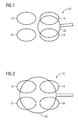
- FIG 1
- illustrates a schematic top view of an induction cooking hob according to a preferred embodiment of the present invention,
- FIG 2
- illustrates a further schematic top view of the induction cooking hob according to the preferred embodiment of the present invention,
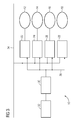
- FIG 3
- illustrates a schematic block diagram of the induction cooking hob according to the preferred embodiment of the present invention,
- FIG 4
- illustrates a schematic top view of the induction cooking hob according to a further embodiment of the present invention,
- FIG 5
- illustrates a schematic diagram of the relationships between the frequency and the power of an induction heating generator according to the preferred embodiment of the present invention,
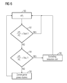
- FIG 6
- illustrates a schematic flow chart diagram of an algorithm for evaluating estimated powers of the inductions coils according to the preferred embodiment of the present invention, and
- FIG 7
- illustrates a schematic flow chart diagram of an algorithm for a convergence power routine according to the preferred embodiment of the present invention.
-
FIG 1 illustrates a schematic top view of aninduction cooking hob 10 according to a preferred embodiment of the present invention. In this example, theinduction cooking hob 10 comprises fourinduction coils induction cooking hob 10 may comprise an arbitrary number of induction coils arranged in matrix from. In this example, theinduction coils induction coils induction coils - A
frying pan 20 is arranged above thesecond induction coil 14 and thefourth induction coil 18. In this case, thesecond induction coil 14 and thefourth induction coil 18 are activated, while thefirst induction coil 12 and thethird induction coil 16 remain deactivated. The heated area of theinduction cooking hob 10 can be adapted to the size of thefrying pan 20. -
FIG 2 illustrates a further schematic top view of theinduction cooking hob 10 according to the preferred embodiment of the present invention. Theinduction cooking hob 10 comprises the fourinduction coils frying pan 20 is arranged above the induction coils 12, 14, 16 and 18. All fourinduction coils frying pan 20 inFIG 2 is bigger than thefrying pan 20 shown inFIG 1 . -
FIG 3 illustrates a schematic block diagram of theinduction cooking hob 10 according to the preferred embodiment of the present invention. - The
induction cooking hob 10 comprises the fourinduction coils dedicated induction generator induction generators induction generator power supply line 34. Saidpower supply line 34 provides rectified mains voltage for theinduction generators - Further, the
induction generators control unit 30 via control lines 36. Eachinduction generator control unit 30 is connected to auser interface 32. - As mentioned above, the four
induction coils - The four
induction coils induction coils induction coils induction coils induction coils induction coil induction coils induction coil - An algorithm of the present invention manages the activation of each group of induction coils 12, 14, 16 and/or 18 according to the user's request, wherein acoustic interference noise is avoided. The heating or cooking process includes a plurality of subsequent fixed time cycles, so that each time cycle has the same time period. The time cycle takes between three seconds and ten seconds, preferably six seconds. The time cycle is subdivided into one or more flexible time slots, so that the number and time period of said time slots are variable.
- The user sets a requested power rPj for each
induction coil induction coil induction coils - The different requested powers rP(i) of the induction coils 12, 14, 16 and 18 to be activated are ordered in an array of requested powers

wherein rP(i+1) > rP(i),
and wherein Nts is the number of time slots in each time cycle. In the example mentioned above the array of requested powers is given by
- Further a corresponding weight array

is defined in order to indicate the number of induction coils 12, 14, 16 and/or 18 having the same requested power rP(i). In this example, the weight array {2, 2} and the array of different requested powers {500 W, 1000 W} indicate that the requested power rP(i) for two induction coils is rP(1) = rP1 = rP2 = 500 W and for the other two induction coils is rP(2) = rP3 = rP4 = 1000 W. - A current power cPj of each
induction coil - The number Nic(i) of activated
induction coils 

wherein i > 1,
and wherein Nic is the number of induction coils 12, 14, 16 and/or 18 to be activated. The average power aP(i) of each time slot i is given by

wherein i > 1. - The durations T(i) of the time slots i are given by

- The percentage power pP(i) for each
induction coil 
- For the example mentioned above the percentage powers pP(i) for each induction coil in each time slot i are given by:
rPj time slot 1 T(1) = 0.66 time slot 2 T(2) = 0.33 pP(1) pP(2) 500 W 0.25 500 W 0.25 1000 W 0.25 0.5 1000 W 0.25 0.5 - The total requested power rP = 3000 W is delivered in two time slots, wherein the duration of the first time slot is T(1) = 0.66 and the duration of the second time slot is T(2) = 0.33 of the total time cycle. In the first time slot the total power is splitted equally on four
induction coils induction coil induction coils induction coils - The current powers cP(i) for each induction coil in the first and second time slots are given by:
rPj time slot 1 T(1) = 0.66 time slot 2 T(2) = 0.33 aPj cP(1) cP(2) 500 W 750 W 500 W 500 W 750 W 500 W 1000 W 750 W 1500 W 1000 W 1000 W 750 W 1500 W 1000 W - According to another example one group of four
induction coils induction coil induction coil rPj time slot 1 T(1) = 1.0 pP(1) 500 W 0.25 500 W 0.25 500 W 0.25 500 W 0.25 - In this special case the time cycle includes only one time slot 1. The current powers cP(i) for each induction coil in the one time slot 1 are given by:
rPj time slot 1 T(1) = 1.0 aPj cP(1) 500 W 500 W 500 W 500 W 500 W 500 W 500 W 500 W 500 W 500 W 500 W 500 W - According to the next example four
induction coils induction coil rPj time slot 1 T(1) = 0.4 time slot 2 T(2) = 0.3 time slot 3 T(3) = 0.2 time slot 4 T(4) = 0.1 pP(1) pP(2) pP(3) pP(4) 200 W 0.25 400 W 0.25 0.33 600 W 0.25 0.33 0.5 800 W 0.25 0.33 0.5 1.0 - The current powers cP(i) for the activated
induction coils rPj time slot 1 T(1) = 0.4 time slot 2 T(2) = 0.3 time slot 3 T(3) = 0.2 time slot 4 T(4) = 0.1 aPi cP(1) cP(2) cP(3) cP (4) 200 W 500 W 200 W 400 W 500 W 660 W 400 W 600 W 500 W 660 W 1000 W 600 W 800 W 500 W 660 W 1000 W 2000 W 800 W - In the next example one
induction coil induction coils induction coils rPi time slot 1 T(1) = 0.57 time slot 2 T(2) = 0.43 pP(1) pP(2) 500 W 0.25 1000 W 0.25 0.33 1000 W 0.25 0.33 1000 W 0.25 0.33 - The current powers cP(i) for activated
induction coils rPi time slot 1 T(1) = 0.57 time slot 2 T(2) = 0.43 aPj cP(1) cP(2) 500 W 875 W 500 W 1000 W 875 W 1155 W 1000 W 1000 W 875 W 1155 W 1000 W 1000 W 875 W 1155 W 1000 W - According to a further example two single induction coils 12, 14, 16 and/or 18 have the requested power rP1 = 500 W and rP2 = 700 W and one group with two
induction coils induction coils rPj time slot 1 T(1) = 0.625 time slot 2 T(2) = 0.188 time slot 2 T(3) = 0.187 pP(1) pP(2) pP(2) 500 W 0.25 700 W 0.25 0.33 1000 W 0.25 0.33 0.5 1000 W 0.25 0.33 0.5 - The current powers cP(i) for activated
induction coils rPj time slot 1 T(1) = 0.625 time slot 2 T(2) = 0.188 time slot 2 T(3) = 0.187 aPj cP(1) cP(2) cP(3) 500 W 800 W 500 W 700 W 800 W 1056 W 700 W 1000 W 800 W 1056 W 1600 W 1000 W 1000 W 800 W 1056 W 1600 W 1000 W -
FIG 4 illustrates a schematic top view of theinduction cooking hob 10 according to a further embodiment of the present invention. Theinduction cooking hob 10 comprises sixinduction coils - According to an example the induction coils 12, 14, 16, 18, 38 and 40 have the requested powers rP1 = 200 W, rP2 = 200 W, rP3 = 300 W, rP4 = 300 W, rP5 = 400 W and rP6 = 700 W. Thus, the total requested power of the induction coils 12, 14, 16, 18, 38 and 40 is rP = 2100 W. Since two pairs of
induction coils
{200 W, 300 W, 400 W, 700 W},
and the weight array is given by
- There are four groups of induction coils 12, 14, 16, 18, 38 and 40. The number of time slots corresponds with said number of groups:

- The numbers Nic(i) of activated
induction coils 



- The average powers aP(i) for the time slots i are given by



- The durations T(i) of the time slots i are given by



- The percentage powers pPi for each induction coil in each time slot are given by:


- The percentage powers pPi for each induction coil in each time slot are shown in detail below:
rPj time slot 1 T(1) = 0.57 time slot 2 T(2) = 0.19 time slot 3 T(3) = 0.09 time slot 4 T(4) = 0.15 pP(1) pP(2) pP(3) pP (4) 200 W 0.16 200 W 0.16 300 W 0.16 0.25 300 W 0.16 0.25 400 W 0.16 0.25 0.5 700 W 0.16 0.25 0.5 1.0 - The current powers cP(i) for the activated induction coils in each time slot are given by:
rPj time slot 1 T(1) = 0.57 time slot 2 T(2) = 0.19 time slot 3 T(3) = 0.09 time slot 4 T(4) = 0.15 aPj cP(1) cP(2) cP(3) cP (4) 200 W 336 W 200 W 200 W 336 W 200 W 300 W 336 W 525 W 300 W 300 W 336 W 525 W 300 W 400 W 336 W 525 W 1050 W 400 W 700 W 336 W 525 W 1050 W 2100 W 700 W -
FIG 5 illustrates a schematic diagram of therelationships induction heating generator - A first diagram 42 shows the relationship between the frequency f and the power P of the
induction heating generator induction heating generator - In order to avoid the bad coverage of the cooking pot on the
corresponding induction coil -
FIG 6 illustrates a schematic flow chart diagram of an algorithm for evaluating estimated powers of the inductions coils 12, 14, 16, 18, 38 and/or 40 according to the preferred embodiment of the present invention. - In a
first step 50 the real powers ePj of each induction coil j are estimated. In anext step 52 the relation between the estimated power ePj and requested power rPj of each induction coil j is compared with a predetermined high threshold value ThrH. For example, said high threshold value ThrH is about 70 %. If the relation between the estimated power ePj and requested power rPj of the induction coil j is bigger than the high threshold value ThrH, then step 50 is activated again. If the relation between the estimated power ePj and requested power rPj of the induction coil j is smaller than the high threshold value ThrH, then afurther step 54 is activated. - In the
step 54 the relation between the estimated power ePj and requested power rPj of the induction coil j is compared with a predetermined low threshold value ThrL. For example, said low threshold value ThrL is about 30 %. If the relation between the estimated power ePj and requested power rPj of the induction coil j is smaller than the low threshold value ThrL, then the induction coil j is excluded instep 56. If the relation between the estimated power ePj and requested power rPj of the induction coil j is bigger than the low threshold value ThrL, then a convergence power routine is performed instep 58. -
FIG 7 illustrates a schematic flow chart diagram of an algorithm for aconvergence power routine 58 according to the preferred embodiment of the present invention. - As a first step 60 a time warp is performed. In this example, the time wrap extends two time cycles. In a next step 62 a power loss IPj of each induction coil j is calculated. A total power loss is given by the sum of power losses IPj of all activated induction coils j. In a
further step 64 the power losses IPj are ordered into a power loss array
step 68. In thestep 68 the requested power rPj is reduced of a quantity equal to a certain percentage quotation of the power loss of the induction coil j. The decrement of the requested power of the induction coil j is stopped, when IPj is decreasing within the threshold value Thr. Further, the original requested power is checked periodically in order to avoid a permanent reduction of power. - Although an illustrative embodiment of the present invention has been described herein with reference to the accompanying drawing, it is to be understood that the present invention is not limited to that precise embodiment, and that various other changes and modifications may be affected therein by one skilled in the art without departing from the scope or spirit of the invention. All such changes and modifications are intended to be included within the scope of the invention as defined by the appended claims.
-
- 10
- induction cooking hob
- 12
- first induction coil
- 14
- second induction coil
- 16
- third induction coil
- 18
- fourth induction coil
- 20
- frying pan
- 22
- first induction generator
- 24
- second induction generator
- 26
- third induction generator
- 28
- fourth induction generator
- 30
- control unit
- 32
- user interface
- 34
- power supply line
- 36
- control line
- 38
- fifth induction coil
- 40
- sixth induction coil
- 42
- diagram of frequency as function of the delivered power
- 44
- diagram of frequency as function of the delivered power
- 50
- step of estimating the power
- 52
- step of comparing the estimated power
- 54
- step of further comparing the estimated power
- 56
- step of excluding the induction coil
- 58
- step of performing the convergence power routine
- 60
- step of time warp
- 62
- step of calculating the power loss
- 64
- step of updating the power loss array
- 66
- step of checking the decrease of power
- 68
- step of reducing the requested power
- P
- power of an induction coil
- rP
- total requested power of the induction coils
- rPj
- requested power of the j-th induction coil
- pP(i)
- percentage power of each induction coil in the time slot i
- cP(i)
- current power of each induction coil in the time slot i
- aPj
- average power of the j-th induction coil
- Nts
- number of time slots
- Nic
- number of induction coils to be activated
- Nic(i)
- number of activated induction coils in the time slot i
- ts
- time slot
- T(i)
- duration of time slot i
- f
- frequency
- ePj
- estimated power of the j-th induction coil
- ThrH
- high threshold value
- ThrL
- low threshold value
- IPj
- power loss of the j-th induction coil
- Thr
- threshold value for the decrease of power loss
Claims (15)
- A method for controlling an induction cooking hob (10) including a number of induction coils (12, 14, 16, 18; 38, 40), wherein a heating process includes a plurality of subsequent fixed time cycles subdivided into one or more flexible time slots (ts), and wherein each induction coil (12, 14, 16, 18; 38, 40) is driven by at least one dedicated induction generator (22, 24, 26, 28), and wherein the method comprises the following steps:- setting a requested power (rPj) for each induction coil (12, 14, 16, 18; 38, 40) to be activated by a user,- defining at least one group of one or more induction coils (12, 14, 16, 18; 38, 40), wherein the induction coils (12, 14, 16, 18; 38, 40) of one group have the same requested power (rPj),- determining a number of time slots (Nts) for each time cycle, wherein the number of time slots (Nts) is given by the number of groups of induction coils (12, 14, 16, 18; 38, 40) having the same requested power (rPj),- activating all groups of induction coils (12, 14, 16, 18; 38, 40) to be activated during a first time slot (ts1) at a same current power (cP(1)) for a calculated duration (T(1)), and- activating a part of groups of induction coils (12, 14, 16, 18; 38, 40) to be activated during at least one further time slot (ts2, ts3, ts4) at the same current powers (cP(2), cP(3), cP(4)) in each time slot (ts2, ts3, ts4) for a calculated duration (T(2), T(3), T(4)), if more than one group of induction coils (12, 14, 16, 18; 38, 40) are defined,- so that an average current power (aPj) of each induction coil (12, 14, 16, 18; 38, 40) within the time cycle corresponds with the requested power (rPj) for said induction coil (12, 14, 16, 18; 38, 40).
- The method according to claim 1,
characterised in that
the method is provided for controlling an induction cooking hob (10), wherein the induction coils (12, 14, 16, 18; 38, 40) are arranged as a matrix. - The method according to claim 1 or 2,
characterised in that
an array ({rP(1), rP(2), rP(3), ..., rP(Nts)}) of different requested powers (rP(i)) is defined, in which said different requested powers increase, wherein the number of said different requested powers (rP(i)) corresponds with the number of time slots (Nts) in each time cycle, and wherein a corresponding weight array ({w(1), w(2), ..., w(Nts)}) is defined in order to indicate the number of induction coils (12, 14, 16, 18; 38, 40) having the same requested power (rP(i)). - The method according to any one of the preceding claims,
characterised in that
the number (Nic(1)) of activated induction coils (12, 14, 16, 18; 38, 40) in the first time slot is given by the number (Nic) of induction coils (12, 14, 16, 18; 38, 40) to be activated, and the number (Nic(i)) of activated induction coils (12, 14, 16, 18; 38, 40) in the further time slots is given by:
and wherein w(i) is the number of activated induction coils (12, 14, 16, 18; 38, 40) in the i-th time slot. - The method according to any one of the preceding claims, characterised in that the average power (aP(1)) in the first time slot is given by:

wherein rP(1) is the lowest requested power and Nic(1) is the number of activated induction coils (12, 14, 16, 18; 38, 40) in the first time slot, and the average power (aP(1)) in the further time slots (i) is given by:
- The method according to any one of the preceding claims, characterised in that
the durations (T(i)) of the time slots (i) are given by:
wherein aP(i) is the average power of the induction coils (12, 14, 16, 18; 38, 40) and rP is the total requested power. - The method according to any one of the preceding claims, characterised in that
the percentage power (pP(i)) for each induction coil (12, 14, 16, 18; 38, 40) within one time slot (i) is given by:
wherein Nic(i) is the number of activated induction coils in the i-th time slot. - The method according to any one of the preceding claims,
characterised in that
an estimated power (ePj) for each induction coil (12, 14, 16, 18; 38, 40) is determined and compared with the requested power (rPj) for said induction coil (12, 14, 16, 18; 38, 40), wherein the induction coil (12, 14, 16, 18; 38, 40) is excluded, if the relation between the estimated power (ePj) and the requested power (rPj) exceeds a high threshold value (ThrH) and/or falls below a low threshold value (ThrH). - The method according to claim 8,
characterised in that
a power loss (lPj) for each induction coil (12, 14, 16, 18; 38, 40) is determined, wherein said power loss (lPj) is given by the difference between the requested power (rPj) and the estimated power (ePj). - The method according to claim 9,
characterised in that
the power losses (lPj) of the induction coils (12, 14, 16, 18; 38, 40) form a power loss array ({lP1, lP2,..., lP(Nic)}), wherein said power loss array ({lP1, lP2,..., lP(Nic)}) is periodically updated. - The method according to any one of the preceding claims,
characterised in that
the duration of each time cycle is between three seconds and ten seconds, in particular six seconds. - An induction cooking hob (10) including a number of induction coils (12, 14, 16, 18; 38, 40), wherein a heating process performed by said induction cooking hob (10) includes a plurality of subsequent fixed time cycles subdivided into one or more flexible time slots (ts), and wherein the induction cooking hob (10) includes at least one induction generator (22, 24, 26, 28) for each induction coil (12, 14, 16, 18; 38, 40), so that each induction coil (12, 14, 16, 18; 38, 40) is driven by at least one dedicated induction generator (22, 24, 26, 28),
characterised in that
the induction cooking hob (10) is provided for a method according to any one of the claims 1 to 11. - The induction cooking hob according to claim 12
characterised in that
the induction coils (12, 14, 16, 18; 38, 40) are arranged as a matrix. - The induction cooking hob according to claim 12 or 13,
characterised in that
the induction cooking hob (10) includes at least one control unit (30) for controlling the induction generators (22, 24, 26, 28), wherein preferably the induction cooking hob (10) includes at least one user interface (32) connected or connectable to the control unit (30). - A computer program stored in a computer usable medium, comprising computer readable program means for causing a computer to perform a method according to any one of the claims 1 to 11.
Priority Applications (6)
| Application Number | Priority Date | Filing Date | Title |
|---|---|---|---|
| EP15176048.5A EP3116288B1 (en) | 2015-07-09 | 2015-07-09 | Method for controlling an induction cooking hob including a number of induction coils |
| BR112017028022-1A BR112017028022B1 (en) | 2015-07-09 | 2016-06-28 | METHOD FOR CONTROLING AN INDUCTION COOKING HOB AND INDUCTION COOKING HOB |
| CN201680036912.1A CN107787603B (en) | 2015-07-09 | 2016-06-28 | Method for controlling an induction cooking hob comprising a plurality of induction coils |
| AU2016290360A AU2016290360B2 (en) | 2015-07-09 | 2016-06-28 | Method for controlling an induction cooking hob including a number of induction coils |
| US15/572,932 US10772161B2 (en) | 2015-07-09 | 2016-06-28 | Method for controlling an induction cooking hob including a number of induction coils |
| PCT/EP2016/064952 WO2017005541A1 (en) | 2015-07-09 | 2016-06-28 | Method for controlling an induction cooking hob including a number of induction coils |
Applications Claiming Priority (1)
| Application Number | Priority Date | Filing Date | Title |
|---|---|---|---|
| EP15176048.5A EP3116288B1 (en) | 2015-07-09 | 2015-07-09 | Method for controlling an induction cooking hob including a number of induction coils |
Publications (2)
| Publication Number | Publication Date |
|---|---|
| EP3116288A1 true EP3116288A1 (en) | 2017-01-11 |
| EP3116288B1 EP3116288B1 (en) | 2020-05-13 |
Family
ID=53540682
Family Applications (1)
| Application Number | Title | Priority Date | Filing Date |
|---|---|---|---|
| EP15176048.5A Active EP3116288B1 (en) | 2015-07-09 | 2015-07-09 | Method for controlling an induction cooking hob including a number of induction coils |
Country Status (5)
| Country | Link |
|---|---|
| US (1) | US10772161B2 (en) |
| EP (1) | EP3116288B1 (en) |
| CN (1) | CN107787603B (en) |
| AU (1) | AU2016290360B2 (en) |
| WO (1) | WO2017005541A1 (en) |
Cited By (1)
| Publication number | Priority date | Publication date | Assignee | Title |
|---|---|---|---|---|
| EP3432682B1 (en) * | 2017-07-18 | 2026-04-08 | Whirlpool Corporation | Method for operating an induction cooking hob and cooking hob using such method |
Families Citing this family (2)
| Publication number | Priority date | Publication date | Assignee | Title |
|---|---|---|---|---|
| CN111742613B (en) * | 2018-02-23 | 2022-06-28 | 三菱电机株式会社 | Induction heating cooker |
| EP3592109B1 (en) * | 2018-07-01 | 2021-03-17 | Electrolux Appliances Aktiebolag | Cooking hob |
Citations (3)
| Publication number | Priority date | Publication date | Assignee | Title |
|---|---|---|---|---|
| WO2008122495A1 (en) * | 2007-04-09 | 2008-10-16 | BSH Bosch und Siemens Hausgeräte GmbH | Hob and method for operating a hob |
| EP2389045A1 (en) * | 2010-05-21 | 2011-11-23 | FagorBrandt SAS | Method for controlling the operation of a set of inductors of an induction cooktop |
| EP2846607A1 (en) * | 2013-09-05 | 2015-03-11 | Electrolux Appliances Aktiebolag | An induction cooking hob including a cooking area with three or more induction coils and a method for controlling a cooking area |
Family Cites Families (17)
| Publication number | Priority date | Publication date | Assignee | Title |
|---|---|---|---|---|
| DE102006058874B4 (en) * | 2006-12-06 | 2024-10-31 | E.G.O. Elektro-Gerätebau GmbH | Method for controlling induction heating devices in an electric cooking appliance |
| ATE528591T1 (en) * | 2008-05-30 | 2011-10-15 | Electrolux Home Prod Corp | INTERACTION DEVICE |
| ES2382431B1 (en) * | 2009-07-29 | 2013-05-08 | BSH Electrodomésticos España S.A. | COOKING DEVICE WITH AT LEAST TWO HEATING AREAS |
| EP3771288B1 (en) * | 2009-10-05 | 2021-12-15 | Whirlpool Corporation | Method for supplying power to induction cooking zones of an induction cooking hob having a plurality of power converters, and induction cooking hob using such method |
| EP3270661A1 (en) * | 2011-03-28 | 2018-01-17 | Samsung Electronics Co., Ltd. | Control method of induction heating cooker |
| KR101844405B1 (en) * | 2011-04-08 | 2018-04-03 | 삼성전자주식회사 | Induction heating cooker and control method thereof |
| EP2731402B1 (en) * | 2012-11-09 | 2015-08-19 | Electrolux Home Products Corporation N.V. | A method for controlling an induction cooking hob with a plurality of induction coils and an induction cooking hob |
| EP2779788B1 (en) * | 2013-03-11 | 2015-08-19 | Electrolux Appliances Aktiebolag | A method for assigning induction coils of an induction cooking hob and an induction cooking hob |
| EP2800453B1 (en) * | 2013-04-30 | 2018-09-19 | Electrolux Appliances Aktiebolag | Hob and methods for operating such a hob |
| EP3028535B2 (en) * | 2013-07-31 | 2022-09-21 | BSH Hausgeräte GmbH | Cooktop device |
| US9470423B2 (en) * | 2013-12-02 | 2016-10-18 | Bose Corporation | Cooktop power control system |
| US10455647B2 (en) * | 2014-11-26 | 2019-10-22 | Samsung Electronics Co., Ltd. | Cooking apparatus and method for controlling the same |
| WO2017068716A1 (en) * | 2015-10-23 | 2017-04-27 | 三菱電機株式会社 | Inductive heating cooker |
| KR102629987B1 (en) * | 2016-09-01 | 2024-01-29 | 삼성전자주식회사 | Cooking apparatus and method for controlling the same |
| KR102642315B1 (en) * | 2017-02-20 | 2024-03-04 | 삼성전자주식회사 | Cooking apparatus and method of controlling thereof |
| KR102329134B1 (en) * | 2017-04-28 | 2021-11-19 | 삼성전자주식회사 | Cooking apparatus and control method thereof |
| US12302478B2 (en) * | 2018-04-23 | 2025-05-13 | Whirlpool Corporation | Control circuits and methods for distributed induction heating devices |
-
2015
- 2015-07-09 EP EP15176048.5A patent/EP3116288B1/en active Active
-
2016
- 2016-06-28 CN CN201680036912.1A patent/CN107787603B/en active Active
- 2016-06-28 WO PCT/EP2016/064952 patent/WO2017005541A1/en not_active Ceased
- 2016-06-28 AU AU2016290360A patent/AU2016290360B2/en active Active
- 2016-06-28 US US15/572,932 patent/US10772161B2/en active Active
Patent Citations (3)
| Publication number | Priority date | Publication date | Assignee | Title |
|---|---|---|---|---|
| WO2008122495A1 (en) * | 2007-04-09 | 2008-10-16 | BSH Bosch und Siemens Hausgeräte GmbH | Hob and method for operating a hob |
| EP2389045A1 (en) * | 2010-05-21 | 2011-11-23 | FagorBrandt SAS | Method for controlling the operation of a set of inductors of an induction cooktop |
| EP2846607A1 (en) * | 2013-09-05 | 2015-03-11 | Electrolux Appliances Aktiebolag | An induction cooking hob including a cooking area with three or more induction coils and a method for controlling a cooking area |
Cited By (1)
| Publication number | Priority date | Publication date | Assignee | Title |
|---|---|---|---|---|
| EP3432682B1 (en) * | 2017-07-18 | 2026-04-08 | Whirlpool Corporation | Method for operating an induction cooking hob and cooking hob using such method |
Also Published As
| Publication number | Publication date |
|---|---|
| US20180146514A1 (en) | 2018-05-24 |
| AU2016290360A1 (en) | 2017-11-23 |
| CN107787603A (en) | 2018-03-09 |
| BR112017028022A2 (en) | 2018-11-06 |
| CN107787603B (en) | 2020-12-29 |
| US10772161B2 (en) | 2020-09-08 |
| WO2017005541A1 (en) | 2017-01-12 |
| EP3116288B1 (en) | 2020-05-13 |
| AU2016290360B2 (en) | 2021-06-24 |
Similar Documents
| Publication | Publication Date | Title |
|---|---|---|
| EP2846607B1 (en) | An induction cooking hob including a cooking area with three or more induction coils and a method for controlling a cooking area | |
| CN104685965B (en) | For controlling method and the induction cook kitchen range of the induction cook kitchen range with multiple induction coils | |
| EP1951003B2 (en) | Control method for induction cooking hob and induction cooking hob adapted to carry out such method | |
| EP2306784A1 (en) | Method for supplying power to induction cooking zones of an induction cooking hob having a plurality of power converters, and induction cooking hob using such method | |
| EP3116288B1 (en) | Method for controlling an induction cooking hob including a number of induction coils | |
| EP3282815B1 (en) | Method for controlling an induction hob | |
| CN109984623A (en) | Cooking apparatus and its clocking method and device | |
| CN112312603A (en) | Heating control method and device for induction cooker and induction cooker | |
| EP3855086A1 (en) | Air conditioner control method and device, and computer storage medium | |
| EP3582587B1 (en) | Method for controlling two cooking zones of an induction cooking hob | |
| US12604373B2 (en) | Induction device | |
| US20220191976A1 (en) | Cooking appliance | |
| DE102019218792A1 (en) | Cooking device | |
| CN109527978A (en) | Cooking mode control method and cooking equipment | |
| WO2025168344A1 (en) | Domestic appliance apparatus | |
| CN118250848A (en) | Heating control method, heating control device, induction heating equipment and storage medium |
Legal Events
| Date | Code | Title | Description |
|---|---|---|---|
| PUAI | Public reference made under article 153(3) epc to a published international application that has entered the european phase |
Free format text: ORIGINAL CODE: 0009012 |
|
| STAA | Information on the status of an ep patent application or granted ep patent |
Free format text: STATUS: THE APPLICATION HAS BEEN PUBLISHED |
|
| AK | Designated contracting states |
Kind code of ref document: A1 Designated state(s): AL AT BE BG CH CY CZ DE DK EE ES FI FR GB GR HR HU IE IS IT LI LT LU LV MC MK MT NL NO PL PT RO RS SE SI SK SM TR |
|
| AX | Request for extension of the european patent |
Extension state: BA ME |
|
| STAA | Information on the status of an ep patent application or granted ep patent |
Free format text: STATUS: REQUEST FOR EXAMINATION WAS MADE |
|
| 17P | Request for examination filed |
Effective date: 20170711 |
|
| RBV | Designated contracting states (corrected) |
Designated state(s): AL AT BE BG CH CY CZ DE DK EE ES FI FR GB GR HR HU IE IS IT LI LT LU LV MC MK MT NL NO PL PT RO RS SE SI SK SM TR |
|
| GRAP | Despatch of communication of intention to grant a patent |
Free format text: ORIGINAL CODE: EPIDOSNIGR1 |
|
| STAA | Information on the status of an ep patent application or granted ep patent |
Free format text: STATUS: GRANT OF PATENT IS INTENDED |
|
| INTG | Intention to grant announced |
Effective date: 20200108 |
|
| GRAS | Grant fee paid |
Free format text: ORIGINAL CODE: EPIDOSNIGR3 |
|
| GRAA | (expected) grant |
Free format text: ORIGINAL CODE: 0009210 |
|
| STAA | Information on the status of an ep patent application or granted ep patent |
Free format text: STATUS: THE PATENT HAS BEEN GRANTED |
|
| AK | Designated contracting states |
Kind code of ref document: B1 Designated state(s): AL AT BE BG CH CY CZ DE DK EE ES FI FR GB GR HR HU IE IS IT LI LT LU LV MC MK MT NL NO PL PT RO RS SE SI SK SM TR |
|
| REG | Reference to a national code |
Ref country code: GB Ref legal event code: FG4D |
|
| REG | Reference to a national code |
Ref country code: CH Ref legal event code: EP |
|
| REG | Reference to a national code |
Ref country code: DE Ref legal event code: R096 Ref document number: 602015052644 Country of ref document: DE |
|
| REG | Reference to a national code |
Ref country code: AT Ref legal event code: REF Ref document number: 1271934 Country of ref document: AT Kind code of ref document: T Effective date: 20200615 |
|
| REG | Reference to a national code |
Ref country code: LT Ref legal event code: MG4D |
|
| REG | Reference to a national code |
Ref country code: NL Ref legal event code: MP Effective date: 20200513 |
|
| PG25 | Lapsed in a contracting state [announced via postgrant information from national office to epo] |
Ref country code: LT Free format text: LAPSE BECAUSE OF FAILURE TO SUBMIT A TRANSLATION OF THE DESCRIPTION OR TO PAY THE FEE WITHIN THE PRESCRIBED TIME-LIMIT Effective date: 20200513 Ref country code: GR Free format text: LAPSE BECAUSE OF FAILURE TO SUBMIT A TRANSLATION OF THE DESCRIPTION OR TO PAY THE FEE WITHIN THE PRESCRIBED TIME-LIMIT Effective date: 20200814 Ref country code: NO Free format text: LAPSE BECAUSE OF FAILURE TO SUBMIT A TRANSLATION OF THE DESCRIPTION OR TO PAY THE FEE WITHIN THE PRESCRIBED TIME-LIMIT Effective date: 20200813 Ref country code: PT Free format text: LAPSE BECAUSE OF FAILURE TO SUBMIT A TRANSLATION OF THE DESCRIPTION OR TO PAY THE FEE WITHIN THE PRESCRIBED TIME-LIMIT Effective date: 20200914 Ref country code: IS Free format text: LAPSE BECAUSE OF FAILURE TO SUBMIT A TRANSLATION OF THE DESCRIPTION OR TO PAY THE FEE WITHIN THE PRESCRIBED TIME-LIMIT Effective date: 20200913 Ref country code: SE Free format text: LAPSE BECAUSE OF FAILURE TO SUBMIT A TRANSLATION OF THE DESCRIPTION OR TO PAY THE FEE WITHIN THE PRESCRIBED TIME-LIMIT Effective date: 20200513 Ref country code: FI Free format text: LAPSE BECAUSE OF FAILURE TO SUBMIT A TRANSLATION OF THE DESCRIPTION OR TO PAY THE FEE WITHIN THE PRESCRIBED TIME-LIMIT Effective date: 20200513 |
|
| PG25 | Lapsed in a contracting state [announced via postgrant information from national office to epo] |
Ref country code: HR Free format text: LAPSE BECAUSE OF FAILURE TO SUBMIT A TRANSLATION OF THE DESCRIPTION OR TO PAY THE FEE WITHIN THE PRESCRIBED TIME-LIMIT Effective date: 20200513 Ref country code: LV Free format text: LAPSE BECAUSE OF FAILURE TO SUBMIT A TRANSLATION OF THE DESCRIPTION OR TO PAY THE FEE WITHIN THE PRESCRIBED TIME-LIMIT Effective date: 20200513 Ref country code: BG Free format text: LAPSE BECAUSE OF FAILURE TO SUBMIT A TRANSLATION OF THE DESCRIPTION OR TO PAY THE FEE WITHIN THE PRESCRIBED TIME-LIMIT Effective date: 20200813 Ref country code: RS Free format text: LAPSE BECAUSE OF FAILURE TO SUBMIT A TRANSLATION OF THE DESCRIPTION OR TO PAY THE FEE WITHIN THE PRESCRIBED TIME-LIMIT Effective date: 20200513 |
|
| REG | Reference to a national code |
Ref country code: AT Ref legal event code: MK05 Ref document number: 1271934 Country of ref document: AT Kind code of ref document: T Effective date: 20200513 |
|
| PG25 | Lapsed in a contracting state [announced via postgrant information from national office to epo] |
Ref country code: AL Free format text: LAPSE BECAUSE OF FAILURE TO SUBMIT A TRANSLATION OF THE DESCRIPTION OR TO PAY THE FEE WITHIN THE PRESCRIBED TIME-LIMIT Effective date: 20200513 Ref country code: NL Free format text: LAPSE BECAUSE OF FAILURE TO SUBMIT A TRANSLATION OF THE DESCRIPTION OR TO PAY THE FEE WITHIN THE PRESCRIBED TIME-LIMIT Effective date: 20200513 |
|
| PG25 | Lapsed in a contracting state [announced via postgrant information from national office to epo] |
Ref country code: SM Free format text: LAPSE BECAUSE OF FAILURE TO SUBMIT A TRANSLATION OF THE DESCRIPTION OR TO PAY THE FEE WITHIN THE PRESCRIBED TIME-LIMIT Effective date: 20200513 Ref country code: EE Free format text: LAPSE BECAUSE OF FAILURE TO SUBMIT A TRANSLATION OF THE DESCRIPTION OR TO PAY THE FEE WITHIN THE PRESCRIBED TIME-LIMIT Effective date: 20200513 Ref country code: RO Free format text: LAPSE BECAUSE OF FAILURE TO SUBMIT A TRANSLATION OF THE DESCRIPTION OR TO PAY THE FEE WITHIN THE PRESCRIBED TIME-LIMIT Effective date: 20200513 Ref country code: ES Free format text: LAPSE BECAUSE OF FAILURE TO SUBMIT A TRANSLATION OF THE DESCRIPTION OR TO PAY THE FEE WITHIN THE PRESCRIBED TIME-LIMIT Effective date: 20200513 Ref country code: CZ Free format text: LAPSE BECAUSE OF FAILURE TO SUBMIT A TRANSLATION OF THE DESCRIPTION OR TO PAY THE FEE WITHIN THE PRESCRIBED TIME-LIMIT Effective date: 20200513 Ref country code: AT Free format text: LAPSE BECAUSE OF FAILURE TO SUBMIT A TRANSLATION OF THE DESCRIPTION OR TO PAY THE FEE WITHIN THE PRESCRIBED TIME-LIMIT Effective date: 20200513 Ref country code: DK Free format text: LAPSE BECAUSE OF FAILURE TO SUBMIT A TRANSLATION OF THE DESCRIPTION OR TO PAY THE FEE WITHIN THE PRESCRIBED TIME-LIMIT Effective date: 20200513 |
|
| REG | Reference to a national code |
Ref country code: DE Ref legal event code: R097 Ref document number: 602015052644 Country of ref document: DE |
|
| PG25 | Lapsed in a contracting state [announced via postgrant information from national office to epo] |
Ref country code: PL Free format text: LAPSE BECAUSE OF FAILURE TO SUBMIT A TRANSLATION OF THE DESCRIPTION OR TO PAY THE FEE WITHIN THE PRESCRIBED TIME-LIMIT Effective date: 20200513 Ref country code: MC Free format text: LAPSE BECAUSE OF FAILURE TO SUBMIT A TRANSLATION OF THE DESCRIPTION OR TO PAY THE FEE WITHIN THE PRESCRIBED TIME-LIMIT Effective date: 20200513 Ref country code: SK Free format text: LAPSE BECAUSE OF FAILURE TO SUBMIT A TRANSLATION OF THE DESCRIPTION OR TO PAY THE FEE WITHIN THE PRESCRIBED TIME-LIMIT Effective date: 20200513 |
|
| REG | Reference to a national code |
Ref country code: CH Ref legal event code: PL |
|
| PLBE | No opposition filed within time limit |
Free format text: ORIGINAL CODE: 0009261 |
|
| STAA | Information on the status of an ep patent application or granted ep patent |
Free format text: STATUS: NO OPPOSITION FILED WITHIN TIME LIMIT |
|
| 26N | No opposition filed |
Effective date: 20210216 |
|
| GBPC | Gb: european patent ceased through non-payment of renewal fee |
Effective date: 20200813 |
|
| REG | Reference to a national code |
Ref country code: BE Ref legal event code: MM Effective date: 20200731 |
|
| PG25 | Lapsed in a contracting state [announced via postgrant information from national office to epo] |
Ref country code: CH Free format text: LAPSE BECAUSE OF NON-PAYMENT OF DUE FEES Effective date: 20200731 Ref country code: LU Free format text: LAPSE BECAUSE OF NON-PAYMENT OF DUE FEES Effective date: 20200709 Ref country code: LI Free format text: LAPSE BECAUSE OF NON-PAYMENT OF DUE FEES Effective date: 20200731 |
|
| PG25 | Lapsed in a contracting state [announced via postgrant information from national office to epo] |
Ref country code: BE Free format text: LAPSE BECAUSE OF NON-PAYMENT OF DUE FEES Effective date: 20200731 Ref country code: SI Free format text: LAPSE BECAUSE OF FAILURE TO SUBMIT A TRANSLATION OF THE DESCRIPTION OR TO PAY THE FEE WITHIN THE PRESCRIBED TIME-LIMIT Effective date: 20200513 |
|
| PG25 | Lapsed in a contracting state [announced via postgrant information from national office to epo] |
Ref country code: GB Free format text: LAPSE BECAUSE OF NON-PAYMENT OF DUE FEES Effective date: 20200813 Ref country code: IE Free format text: LAPSE BECAUSE OF NON-PAYMENT OF DUE FEES Effective date: 20200709 |
|
| PG25 | Lapsed in a contracting state [announced via postgrant information from national office to epo] |
Ref country code: TR Free format text: LAPSE BECAUSE OF FAILURE TO SUBMIT A TRANSLATION OF THE DESCRIPTION OR TO PAY THE FEE WITHIN THE PRESCRIBED TIME-LIMIT Effective date: 20200513 Ref country code: MT Free format text: LAPSE BECAUSE OF FAILURE TO SUBMIT A TRANSLATION OF THE DESCRIPTION OR TO PAY THE FEE WITHIN THE PRESCRIBED TIME-LIMIT Effective date: 20200513 Ref country code: CY Free format text: LAPSE BECAUSE OF FAILURE TO SUBMIT A TRANSLATION OF THE DESCRIPTION OR TO PAY THE FEE WITHIN THE PRESCRIBED TIME-LIMIT Effective date: 20200513 |
|
| PG25 | Lapsed in a contracting state [announced via postgrant information from national office to epo] |
Ref country code: MK Free format text: LAPSE BECAUSE OF FAILURE TO SUBMIT A TRANSLATION OF THE DESCRIPTION OR TO PAY THE FEE WITHIN THE PRESCRIBED TIME-LIMIT Effective date: 20200513 |
|
| P01 | Opt-out of the competence of the unified patent court (upc) registered |
Effective date: 20230625 |
|
| PGFP | Annual fee paid to national office [announced via postgrant information from national office to epo] |
Ref country code: DE Payment date: 20250728 Year of fee payment: 11 |
|
| PGFP | Annual fee paid to national office [announced via postgrant information from national office to epo] |
Ref country code: IT Payment date: 20250721 Year of fee payment: 11 |
|
| PGFP | Annual fee paid to national office [announced via postgrant information from national office to epo] |
Ref country code: FR Payment date: 20250725 Year of fee payment: 11 |