EP3116257A1 - Method of making mobile originated calls using user equipment in iops dual plmn mode of operation - Google Patents
Method of making mobile originated calls using user equipment in iops dual plmn mode of operation Download PDFInfo
- Publication number
- EP3116257A1 EP3116257A1 EP16176592.0A EP16176592A EP3116257A1 EP 3116257 A1 EP3116257 A1 EP 3116257A1 EP 16176592 A EP16176592 A EP 16176592A EP 3116257 A1 EP3116257 A1 EP 3116257A1
- Authority
- EP
- European Patent Office
- Prior art keywords
- plmn
- user equipment
- call
- iops
- primary
- Prior art date
- Legal status (The legal status is an assumption and is not a legal conclusion. Google has not performed a legal analysis and makes no representation as to the accuracy of the status listed.)
- Granted
Links
Images



Classifications
-
- H—ELECTRICITY
- H04—ELECTRIC COMMUNICATION TECHNIQUE
- H04W—WIRELESS COMMUNICATION NETWORKS
- H04W60/00—Affiliation to network, e.g. registration; Terminating affiliation with the network, e.g. de-registration
- H04W60/005—Multiple registrations, e.g. multihoming
-
- H—ELECTRICITY
- H04—ELECTRIC COMMUNICATION TECHNIQUE
- H04W—WIRELESS COMMUNICATION NETWORKS
- H04W8/00—Network data management
- H04W8/18—Processing of user or subscriber data, e.g. subscribed services, user preferences or user profiles; Transfer of user or subscriber data
- H04W8/20—Transfer of user or subscriber data
-
- H—ELECTRICITY
- H04—ELECTRIC COMMUNICATION TECHNIQUE
- H04W—WIRELESS COMMUNICATION NETWORKS
- H04W48/00—Access restriction; Network selection; Access point selection
- H04W48/18—Selecting a network or a communication service
-
- H—ELECTRICITY
- H04—ELECTRIC COMMUNICATION TECHNIQUE
- H04W—WIRELESS COMMUNICATION NETWORKS
- H04W76/00—Connection management
- H04W76/10—Connection setup
- H04W76/18—Management of setup rejection or failure
-
- H—ELECTRICITY
- H04—ELECTRIC COMMUNICATION TECHNIQUE
- H04W—WIRELESS COMMUNICATION NETWORKS
- H04W8/00—Network data management
- H04W8/22—Processing or transfer of terminal data, e.g. status or physical capabilities
- H04W8/24—Transfer of terminal data
-
- H—ELECTRICITY
- H04—ELECTRIC COMMUNICATION TECHNIQUE
- H04M—TELEPHONIC COMMUNICATION
- H04M1/00—Substation equipment, e.g. for use by subscribers
- H04M1/72—Mobile telephones; Cordless telephones, i.e. devices for establishing wireless links to base stations without route selection
- H04M1/724—User interfaces specially adapted for cordless or mobile telephones
-
- H—ELECTRICITY
- H04—ELECTRIC COMMUNICATION TECHNIQUE
- H04W—WIRELESS COMMUNICATION NETWORKS
- H04W76/00—Connection management
- H04W76/50—Connection management for emergency connections
-
- H—ELECTRICITY
- H04—ELECTRIC COMMUNICATION TECHNIQUE
- H04W—WIRELESS COMMUNICATION NETWORKS
- H04W84/00—Network topologies
- H04W84/02—Hierarchically pre-organised networks, e.g. paging networks, cellular networks, WLAN [Wireless Local Area Network] or WLL [Wireless Local Loop]
- H04W84/04—Large scale networks; Deep hierarchical networks
- H04W84/042—Public Land Mobile systems, e.g. cellular systems
-
- H—ELECTRICITY
- H04—ELECTRIC COMMUNICATION TECHNIQUE
- H04W—WIRELESS COMMUNICATION NETWORKS
- H04W88/00—Devices specially adapted for wireless communication networks, e.g. terminals, base stations or access point devices
- H04W88/02—Terminal devices
- H04W88/06—Terminal devices adapted for operation in multiple networks or having at least two operational modes, e.g. multi-mode terminals
-
- H—ELECTRICITY
- H04—ELECTRIC COMMUNICATION TECHNIQUE
- H04W—WIRELESS COMMUNICATION NETWORKS
- H04W92/00—Interfaces specially adapted for wireless communication networks
- H04W92/04—Interfaces between hierarchically different network devices
- H04W92/14—Interfaces between hierarchically different network devices between access point controllers and backbone network device
Definitions
- the present invention is related to a method of making an MO call using a user equipment in an IOPS dual PLMN mode of operation by provide PLMN precedence.
- the 3rd Generation Partnership Project (3GPP) has developed a universal mobile telecommunications system (UMTS) which adopts a wideband code division multiple access (WCDMA) technology capable of providing high frequency spectrum utilization, universal coverage, and high-speed/quality multimedia data transmission.
- UMTS universal mobile telecommunications system
- WCDMA wideband code division multiple access
- UTRAN universal terrestrial radio access network
- NBs Node-Bs
- UE user equipment
- LTE long-term evolution
- the LTE system includes a new radio interface and radio network architecture which provides a high data rate, low latency, packet optimization, and improved system capacity and coverage.
- a radio access network known as an evolved UTRAN (E-UTRAN) includes multiple evolved NBs (eNBs) for communicating with multiple UEs and a core network (CN) which includes a mobility management entity (MME), a serving gateway (SGW) and other devices for non-access stratum (NAS)control.
- E-UTRAN evolved UTRAN
- eNBs evolved NBs
- CN core network
- MME mobility management entity
- SGW serving gateway
- NAS non-access stratum
- the general IOPS architectural requirements include:
- the macro EPC is the EPC which serves an eNB in normal mode of operation, while the local EPC is an entity which provides functionality used by an eNB in IOPS mode of operation in order to support public safety services.
- a nomadic eNB (NeNB) is a nomadic cell which may include a base station, antennas, microwave backhaul and support for local services.
- the NeNB is intended for PS use by providing coverage or additional capacity where coverage was never present (e.g. forest fire or underground rescue) or where coverage is no longer present (e.g. due to natural disaster).
- An isolated E-UTRAN can be created by either an E-UTRAN without normal connectivity with the macro EPC or deployed NeNBs with E-UTRAN functionality provided by a local EPC.
- PLMN public land mobile network
- the present invention aims at providing a method of making an MO call using a user equipment in an IOPS dual PLMN mode of operation by provide PLMN precedence.
- the claimed method includes the user equipment registering on both a first PLMN and a second PLMN, wherein the first PLMN is connected to a macro EPC and the second PLMN is isolated from the macro EPC; the user equipment setting one of the first PLMN and the second PLMN as a primary PLMN and an other one of the first PLMN and the second PLMN as a secondary PLMN randomly, according to a PLMN preference provided by a user of the user equipment, or according to a dialing history of the user equipment; and the user equipment making a first communication attempt by dialing the MO call via the primary PLMN.
- FIG. 1 is a diagram illustrating an IOPS architecture of an E-UTRAN 100 in response to an outage event within the network.
- An isolated E-UTRAN 100A can be created from the E-UTRAN 100 following an event which isolates a part of the E-UTRAN 100 from normal connectivity with the macro EPC or following deployment of standalone E-UTRAN NeNBs within a part of the E-UTRAN 100.
- the isolated E-UTRAN 100A may include (1) operation with no connection to the macro EPC; (2) one or multiple eNBs; (3) interconnection between eNBs; (4) limited backhaul capacity to the macro EPC; and (5) the services required to support local operations (e.g. group communication) in the case of no network coverage or of limited network coverage.
- the isolated E-UTRAN 100A can be created when the outage event has been occurred within the wireless communication system.
- the eNBs in the normal-mode E-UTRAN 100B are connected to the macro EPC by backhaul connection and the macro EPC is connected to the application server.
- the eNBs in the isolated E-UTRAN 100A are able to support services required for local operations even though a connection to the normal mode E-UTRAN 100A, as well as to the macro EPC, has been cut off.
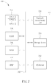
- FIG. 2 is a diagram illustrating UE behavior in an lOPS-capable wireless communication system.
- a coverage area 20A is served by an IOPS-mode eNBI (i.e., isolated from the macro EPC) and a coverage area 20B is served by a normal-mode eNB2 (i.e., connected to the macro EPC).
- PS UE0 ⁇ UE5 represent lOPS-capable mobile devices which can support a PS band.
- the PS UE1 ⁇ UE3 may be served by one or multiple cells in the IOPS-mode eNBI and get connected to each other if the IOPS operation allows it.
- the PS UE4 ⁇ UE5 may be served by one or multiple cells in the normal-mode eNB2 and get connected to each other.
- the PS UE0 is under the coverage of both the IOPS-mode eNBI and the normal-mode eNB2.
- the PS UE0 In an IOPS dual PLMN mode of operation, the PS UE0 is configured to register on both a PLMN of the IOPS-mode eNBI and a PLMN of the normal-mode eNB2. Therefore, the PS UE0 is able to receive mobile terminated (MT) calls from any of the PS UE0 ⁇ UE5.
- MT mobile terminated
- FIG. 3 is a flowchart illustrating a method of making an MO call using a user equipment which operates in the IOPS dual PLMN mode according to an embodiment of the present invention.
- the embodiment depicted in FIG. 3 includes the following steps:
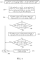
- FIG. 4 is a flowchart illustrating a method of making an MO call using a user equipment which operates in the IOPS dual PLMN mode according to another embodiment of the present invention.
- the embodiment depicted in FIG. 4 includes the following steps:
- FIG. 5 is a flowchart illustrating a method of making an MO call using a user equipment which operates in the IOPS dual PLMN mode according to another embodiment of the present invention.
- the embodiment depicted in FIG. 5 includes the following steps:
- the user equipment when operating in the IOPS dual PLMN mode, is configured to register on both the first PLMN connected to a macro EPC and the second PLMN isolated from the macro EPC.
- All exemplary methods illustrated in FIGs. 3-5 include steps 310 and 330-380, but differ in the steps associated with setting the primary PLMN and the secondary PLMN (steps 320, 322, 324 and 326).
- the user equipment is configured to register on both the first PLMN and the second PLMN.
- the first PLMN may be a normal PLMN connected to the macro EPC which serves the user equipment in normal mode of operation
- the second PLMN may be an IOPS PLMN connected to a local EPC which provides a local IP connectivity and public safety services to the user equipment in IOPS mode of operation when the backhaul to the macro EPC is lost or not available.
- the method and decision associated with IOPS dual PLMN registration does not limit the scope of the present invention.
- steps 320 and 322 are executed for setting the primary PLMN and the secondary PLMN.
- the user equipment is configured to allow or request the user to enter the MO PLMN preference via the user interface.
- an "MO PLMN preference" option may be included in the "Settings" menu of the user interface.
- the user may find "MO PLMN preference” by sequentially tapping Settings->More->...->Mobile Network->IOPS setting->MO PLMN preference, thereby selecting "normal mode” or "IOPS mode” as the MO PLMN preference.
- the method of providing the user interface for acquiring the MO PLMN preference does not limit the scope of the present invention.
- the user equipment may display the user interface, such as a pop-out window, every time when it enters the IOPS dual PLMN mode to request the user to enter the MO PLMN preference.
- the user equipment may display the user interface, such as a pop-out window, every time when it receives an MO call request from the user for requesting the user to enter the PLMN preference.
- the method of providing the user interface for acquiring the MO PLMN preference does not limit the scope of the present invention.
- the user equipment may then set one of the first and the second PLMNs as the primary PLMN and the other one of the first and the second PLMNs as the secondary PLMN according to the MO PLMN preference acquired in step 320.
- step 324 is executed for setting the primary PLMN and the secondary PLMN.
- the user equipment when receiving an MO call request from the user, the user equipment is configured to randomly set one of the first and second PLMNs as the primary PLMN and the other one of the first and second PLMNs as the secondary PLMN.
- step 326 is executed for setting the primary PLMN and the secondary PLMN.
- the user equipment is configured to set one of the first and second PLMNs as the primary PLMN and the other one of the first and second PLMNs as the secondary PLMN according to the dialing history of the user equipment.
- the primary PLMN set according to the dialing history may be one of the first and second PLMNs which was used to make the last successful MO call.
- the primary PLMN set according to the dialing history may be one of the first and second PLMNs which has been selected to make MO calls more frequently during a predetermined past period of time.
- the primary PLMN set according to the dialing history may be one of the first and second PLMNs via which more successful MO calls have been conducted during a predetermined past period of time.
- the contents of the dialing history based on which the primary PLMN and the secondary PLMN are set do not limit the scope of the present invention.
- step 330 the user equipment is configured to make the first communication attempt by dialing the MO call via the primary PLMN. If it is determined that the MO call cannot be conducted via the primary PLMN in step 340, the user equipment is configured to make the second communication attempt by dialing the MO call via the secondary PLMN in step 350. If it is determined that the MO call cannot be conducted via the secondary PLMN in step 360, the user equipment is configured to display the connection failure message in step 370.
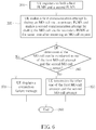
- FIG. 6 is a flowchart illustrating a method of making an MO call using a user equipment which operates in the IOPS dual PLMN mode according to another embodiment of the present invention.
- the embodiment depicted in FIG. 6 includes the following steps:
- the user equipment for implemented the method depicted in FIG. 6 may be a dual SIM dual active (DSDA) terminal in which a first smartcard may be used to listen to a first cell in the primary PLMN and a second smartcard may be used to listen to a second cell in the secondary PLMN simultaneously.
- the user equipment may thus make the first MO call attempt via the primary PLMN and the second MO call attempt via the secondary PLMN at the same time. If it is determined in step 345 that the MO call can be conducted in one of the first MO call attempt and the second MO call attempt, the other one of the first MO call attempt and the second MO call attempt may be terminated in step 355. If it is determined in step 345 that the MO call cannot be conducted via any of first and secondary PLMNs, the user equipment is configured to display the connection failure message in step 370.
- DSDA dual SIM dual active
- FIG. 7 is a functional diagram illustrating a system 700 which may be used in the user equipment for carrying out the present method.
- the system 700 includes a processing component 710, a network connectivity unit 720, random access memory (RAM) 730, read only memory (ROM) 740, a storage device 750, an input/output (I/O) device 760, and a digital signal processor (DSP) 770.
- These components might communicate with one another via a bus 780. In some cases, some of these components may not be present or may be combined in various combinations with one another or with other components not shown. These components might be located in a single physical entity or in more than one physical entity.
- any actions described herein as being taken by the processing component 710 may be taken by the processing component 710 alone or by the processing component 710 in conjunction with one or more components shown or not shown in the drawing, such as with the DSP 770.
- the DSP 770 is shown as a separate component, the DSP 770 might be incorporated into the processing component 710.
- the processing component 710 is configured to execute instructions, codes, computer programs, or scripts which may be accessed from the network connectivity units 720, RAM 730, ROM 740, or the storage device 750.
- the processing component 710 may include one or multiple processors CPU1 ⁇ CPUn for executing the present method simultaneously, serially, or otherwise by one processor.
- the one or multiple processors CPU1 ⁇ CPUn may include one or more application specific integrated circuits (ASICs), DSPs, digital signal processing devices (DSPDs), programmable logic devices (PLDs), field programmable gate arrays (FPGAs), controllers, microcontrollers, microprocessors, or any combination of above.
- ASICs application specific integrated circuits
- DSPs digital signal processing devices
- PLDs programmable logic devices
- FPGAs field programmable gate arrays
- controllers microcontrollers, microprocessors, or any combination of above.
- software code may be stored in the RAM 730, the ROM 740 or the storage device 750 and executed by
- the network connectivity unit 720 may include one or multiple modems, modem banks, Ethernet devices, universal serial bus (USB) interface devices, serial interfaces, token ring devices, fiber distributed data interface (FDDI) devices, wireless local area network (WLAN) devices, radio transceiver devices such as code division multiple access (CDMA) devices, GSM/UMTS/LTE radio transceiver devices, worldwide interoperability for microwave access (WiMAX) devices, and/or other well-known devices for connecting to the eNB.
- the network connectivity unit 720 allows the processing component 710 to communicate with the Internet or one or more telecommunications networks.
- the RAM 730 may be used to store volatile data and instructions that are executed by the processing component 710.
- the ROM 740 may be used to store instructions and data that are read during execution of the instructions.
- the storage device 750 may include various disk-based systems such as hard disk, floppy disk, or optical disk and may be used to store programs that are loaded into the RAM 730 when such programs are selected for execution. Access to both the RAM 730 and the ROM 740 is typically faster than access to the storage device 750, but the storage device 750 can provide larger memory capacity.
- the I/O devices 760 may include one or more of liquid crystal display (LCD) screens, touch screen displays, keyboards, keypads, switches, dials, mice, track balls, voice recognizers, card readers, paper tape readers, printers, video monitors, or other well-known input/output devices.
- LCD liquid crystal display
- the user equipment may be any lOPS-capable transportable electronic device such as a mobile telephone, a personal digital assistant (PDA), a hand-held computer, a tablet, a nettop, a laptop computer, or any device with similar telecommunication capabilities.
- PDA personal digital assistant
- the type of the user equipment does not limit the scope of the present invention.
- UE user equipment
- MS mobile station
- SS subscriber station
- MSS mobile subscriber station
- AMS advanced mobile station
- eNB may be replaced with the terms “BS(base station), “fixed station”, “NB”, “ABS (advanced base station), “AP (access point), etc.
- the user equipment when an lOPS-capable user equipment is registered on both a normal PLMN and an IOPS PLMN, the user equipment is configured to set one of the first PLMN and the second PLMN as a primary PLMN and the other one of the first PLMN and the second PLMN as a secondary PLMN randomly, according to an MO PLMN preference provided by a user of the user equipment, or according to a dialing history of the user equipment. Therefore, the present invention can provide PLMN precedence for the user equipment in the IOPS dual PLMN mode of operation to make MO calls.
Landscapes
- Engineering & Computer Science (AREA)
- Computer Networks & Wireless Communication (AREA)
- Signal Processing (AREA)
- Computer Security & Cryptography (AREA)
- Databases & Information Systems (AREA)
- Mobile Radio Communication Systems (AREA)
Abstract
Description
- The present invention is related to a method of making an MO call using a user equipment in an IOPS dual PLMN mode of operation by provide PLMN precedence.
- The 3rd Generation Partnership Project (3GPP) has developed a universal mobile telecommunications system (UMTS) which adopts a wideband code division multiple access (WCDMA) technology capable of providing high frequency spectrum utilization, universal coverage, and high-speed/quality multimedia data transmission. In the UMTS, a radio access network known as a universal terrestrial radio access network (UTRAN) includes multiple Node-Bs (NBs) for communicating with multiple user equipment (UE). Furthermore, a long-term evolution (LTE) system is now being developed by the 3GPP in order to further improve performance of the UMTS to satisfy users' increasing needs. The LTE system includes a new radio interface and radio network architecture which provides a high data rate, low latency, packet optimization, and improved system capacity and coverage. In the LTE system, a radio access network known as an evolved UTRAN (E-UTRAN) includes multiple evolved NBs (eNBs) for communicating with multiple UEs and a core network (CN) which includes a mobility management entity (MME), a serving gateway (SGW) and other devices for non-access stratum (NAS)control.
- In 3GPP Release 13, a study item was studied on isolated E-UTRAN operations for public safety (IOPS) in support of mission critical network operation for public safety (PS). The main idea laid behind this IOPS study item is to investigate needs and requirements for E-UTRAN operations when encountering connection problems with the macro evolved packet core (EPC).
- For the scenario that an eNB has no backhaul to the macro EPC, the general IOPS architectural requirements include:
- (a) When a UE accesses the eNB in an IOPS mode of operation, a local IP connectivity and transport public safety service shall be provided to the UE by a local EPC connected to the eNB, if authorized.
- (b) An eNB that supports IOPS may enter the IOPS mode of operation after it detects lack of S1 connectivity to the macro EPC. The decision by an eNB to enter the IOPS mode of operation shall be made in accordance with the local policies of the radio access network (RAN) operator.
- According to related 3GPP document, the macro EPC is the EPC which serves an eNB in normal mode of operation, while the local EPC is an entity which provides functionality used by an eNB in IOPS mode of operation in order to support public safety services. A nomadic eNB (NeNB) is a nomadic cell which may include a base station, antennas, microwave backhaul and support for local services. The NeNB is intended for PS use by providing coverage or additional capacity where coverage was never present (e.g. forest fire or underground rescue) or where coverage is no longer present (e.g. due to natural disaster). An isolated E-UTRAN can be created by either an E-UTRAN without normal connectivity with the macro EPC or deployed NeNBs with E-UTRAN functionality provided by a local EPC. There is a need for a method of making mobile originated (MO) calls using a user equipment which is registered on both a normal public land mobile network (PLMN) and an IOPS PLMN.
- The present invention aims at providing a method of making an MO call using a user equipment in an IOPS dual PLMN mode of operation by provide PLMN precedence.
- This is achieved by a method of making an MO call using a user equipment in an IOPS dual PLMN mode of operation according to claims 1 and 7. The dependent claims pertain to corresponding further developments and improvements.
- . As will be seen more clearly from the detailed description following below, the claimed method includes the user equipment registering on both a first PLMN and a second PLMN, wherein the first PLMN is connected to a macro EPC and the second PLMN is isolated from the macro EPC; the user equipment setting one of the first PLMN and the second PLMN as a primary PLMN and an other one of the first PLMN and the second PLMN as a secondary PLMN randomly, according to a PLMN preference provided by a user of the user equipment, or according to a dialing history of the user equipment; and the user equipment making a first communication attempt by dialing the MO call via the primary PLMN.
- In the following, the invention is further illustrated by way of example, taking reference to the accompanying drawings.
-
FIG. 1 is a diagram illustrating an IPSO architecture of an E-UTRAN in response to an outage event within the network. -
FIG. 2 is a diagram illustrating UE behavior in an lOPS-capable wireless communication system. -
FIG. 3 is a flowchart illustrating a method of making an MO call using a user equipment which operates in the IOPS dual PLMN mode according to an embodiment of the present invention. -
FIG. 4 is a flowchart illustrating a method of making an MO call using a user equipment which operates in the IOPS dual PLMN mode according to another embodiment of the present invention. -
FIG. 5 is a flowchart illustrating a method of making an MO call using a user equipment which operates in the IOPS dual PLMN mode according to another embodiment of the present invention. -
FIG. 6 is a flowchart illustrating a method of making an MO call using a user equipment which operates in the IOPS dual PLMN mode according to another embodiment of the present invention. -
FIG. 7 is a functional diagram illustrating a system used in an lOPS-capable wireless communication system for carrying out the present method. -
FIG. 1 is a diagram illustrating an IOPS architecture of anE-UTRAN 100 in response to an outage event within the network. An isolated E-UTRAN 100A can be created from the E-UTRAN 100 following an event which isolates a part of theE-UTRAN 100 from normal connectivity with the macro EPC or following deployment of standalone E-UTRAN NeNBs within a part of theE-UTRAN 100. The isolated E-UTRAN 100A may include (1) operation with no connection to the macro EPC; (2) one or multiple eNBs; (3) interconnection between eNBs; (4) limited backhaul capacity to the macro EPC; and (5) the services required to support local operations (e.g. group communication) in the case of no network coverage or of limited network coverage. - Referring to
FIG. 1 , the isolated E-UTRAN 100A can be created when the outage event has been occurred within the wireless communication system. The eNBs in the normal-mode E-UTRAN 100B are connected to the macro EPC by backhaul connection and the macro EPC is connected to the application server. When the isolated E-UTRAN 100A is created, the eNBs in the isolated E-UTRAN 100A are able to support services required for local operations even though a connection to the normal mode E-UTRAN 100A, as well as to the macro EPC, has been cut off. -
FIG. 2 is a diagram illustrating UE behavior in an lOPS-capable wireless communication system. For illustrative purpose, it is assumed that acoverage area 20A is served by an IOPS-mode eNBI (i.e., isolated from the macro EPC) and acoverage area 20B is served by a normal-mode eNB2 (i.e., connected to the macro EPC). PS UE0~UE5 represent lOPS-capable mobile devices which can support a PS band. The PS UE1~UE3 may be served by one or multiple cells in the IOPS-mode eNBI and get connected to each other if the IOPS operation allows it. The PS UE4~UE5 may be served by one or multiple cells in the normal-mode eNB2 and get connected to each other. The PS UE0 is under the coverage of both the IOPS-mode eNBI and the normal-mode eNB2. - In an IOPS dual PLMN mode of operation, the PS UE0 is configured to register on both a PLMN of the IOPS-mode eNBI and a PLMN of the normal-mode eNB2. Therefore, the PS UE0 is able to receive mobile terminated (MT) calls from any of the PS UE0~UE5. However, there is a need for a method of making MO calls using a user equipment which is registered on both a normal PLMN and an IOPS PLMN.
-
FIG. 3 is a flowchart illustrating a method of making an MO call using a user equipment which operates in the IOPS dual PLMN mode according to an embodiment of the present invention. The embodiment depicted inFIG. 3 includes the following steps: - Step 310:
- the user equipment registers on both a first PLMN which is connected to a macro EPC and a second PLMN which is isolated from the macro EPC; execute
step 320. - Step 320:
- the user equipment allows or requests a user to enter an MO PLMN preference via a user interface; execute
step 330. - Step 322:
- the user equipment sets one of the first and the second PLMNs as a primary PLMN and the other one of the first and the second PLMNs as a secondary PLMN according to the MO PLMN preference; execute
step 340. - Step 330:
- the user equipment makes a first communication attempt by dialing an MO call via the primary PLMN; execute
step 340. - Step 340:
- the user equipment determines if the MO call can be conducted via the primary PLMN; if yes, execute
step 380; if no, executestep 350. - Step 350:
- the user equipment makes a second communication attempt by dialing the MO call via the secondary PLMN; execute
step 360. - Step 360:
- the user equipment determines if the MO call can be conducted via the secondary PLMN; if yes, execute
step 380; if no, executestep 370. - Step 370:
- the user equipment displays a connection failure message; execute
step 380. - Step 380:
- end.
-
FIG. 4 is a flowchart illustrating a method of making an MO call using a user equipment which operates in the IOPS dual PLMN mode according to another embodiment of the present invention. The embodiment depicted inFIG. 4 includes the following steps: - Step 310:
- the user equipment registers on both a first PLMN which is connected to a macro EPC and a second PLMN which is isolated from the macro EPC; execute
step 324. - Step 324:
- the user equipment randomly sets one of the first and second PLMNs as a primary PLMN and the other one of the first and second PLMNs as a secondary PLMN when receiving an MO call request; execute
step 330. - Step 330:
- the user equipment makes a first communication attempt by dialing an MO call via the primary PLMN; execute
step 340. - Step 340:
- the user equipment determines if the MO call can be conducted via the primary PLMN; if yes, execute
step 380; if no, executestep 350. - Step 350:
- the user equipment makes a second communication attempt by dialing the MO call via the secondary PLMN; execute
step 360. - Step 360:
- the user equipment determines if the MO call can be conducted via the secondary PLMN; if yes, execute
step 380; if no, executestep 370. - Step 370:
- the user equipment displays a connection failure message; execute
step 380. - Step 380:
- end.
-
FIG. 5 is a flowchart illustrating a method of making an MO call using a user equipment which operates in the IOPS dual PLMN mode according to another embodiment of the present invention. The embodiment depicted inFIG. 5 includes the following steps: - Step 310:
- the user equipment registers on both a first PLMN which is connected to a macro EPC and a second PLMN which is isolated from the macro EPC; execute
step 326. - Step 326:
- the user equipment sets one of the first and second PLMNs as a primary PLMN and the other one of the first and second PLMNs as a secondary PLMN according to a dialing history; execute
step 330. - Step 330:
- the user equipment makes a first communication attempt by dialing an MO call via the primary PLMN; execute
step 340. - Step 340:
- the user equipment determines if the MO call can be conducted via the primary PLMN; if yes, execute
step 380; if no, executestep 350. - Step 350:
- the user equipment makes a second communication attempt by dialing the MO call via the secondary PLMN; execute
step 360. - Step 360:
- the user equipment determines if the MO call can be conducted via the secondary PLMN; if yes, execute
step 380; if no, executestep 370. - Step 370:
- the user equipment displays a connection failure message; execute
step 380. - Step 380:
- end.
- In the present invention, when operating in the IOPS dual PLMN mode, the user equipment is configured to register on both the first PLMN connected to a macro EPC and the second PLMN isolated from the macro EPC. All exemplary methods illustrated in
FIGs. 3-5 includesteps 310 and 330-380, but differ in the steps associated with setting the primary PLMN and the secondary PLMN (steps - In
step 310, the user equipment is configured to register on both the first PLMN and the second PLMN. In the present invention, the first PLMN may be a normal PLMN connected to the macro EPC which serves the user equipment in normal mode of operation, while the second PLMN may be an IOPS PLMN connected to a local EPC which provides a local IP connectivity and public safety services to the user equipment in IOPS mode of operation when the backhaul to the macro EPC is lost or not available. The method and decision associated with IOPS dual PLMN registration does not limit the scope of the present invention. - In the method depicted in
FIG. 3 ,steps step 320, the user equipment is configured to allow or request the user to enter the MO PLMN preference via the user interface. In an embodiment, an "MO PLMN preference" option may be included in the "Settings" menu of the user interface. For example, the user may find "MO PLMN preference" by sequentially tapping Settings->More->...->Mobile Network->IOPS setting->MO PLMN preference, thereby selecting "normal mode" or "IOPS mode" as the MO PLMN preference. However, the method of providing the user interface for acquiring the MO PLMN preference does not limit the scope of the present invention. - In another embodiment, the user equipment may display the user interface, such as a pop-out window, every time when it enters the IOPS dual PLMN mode to request the user to enter the MO PLMN preference. In yet another embodiment, the user equipment may display the user interface, such as a pop-out window, every time when it receives an MO call request from the user for requesting the user to enter the PLMN preference. However, the method of providing the user interface for acquiring the MO PLMN preference does not limit the scope of the present invention.
- In
step 322, the user equipment may then set one of the first and the second PLMNs as the primary PLMN and the other one of the first and the second PLMNs as the secondary PLMN according to the MO PLMN preference acquired instep 320. - In the method depicted in
FIG. 4 ,step 324 is executed for setting the primary PLMN and the secondary PLMN. Instep 324, when receiving an MO call request from the user, the user equipment is configured to randomly set one of the first and second PLMNs as the primary PLMN and the other one of the first and second PLMNs as the secondary PLMN. - In the method depicted in
FIG. 5 ,step 326 is executed for setting the primary PLMN and the secondary PLMN. Instep 326, the user equipment is configured to set one of the first and second PLMNs as the primary PLMN and the other one of the first and second PLMNs as the secondary PLMN according to the dialing history of the user equipment. In one embodiment, the primary PLMN set according to the dialing history may be one of the first and second PLMNs which was used to make the last successful MO call. In another embodiment, the primary PLMN set according to the dialing history may be one of the first and second PLMNs which has been selected to make MO calls more frequently during a predetermined past period of time. In yet another embodiment, the primary PLMN set according to the dialing history may be one of the first and second PLMNs via which more successful MO calls have been conducted during a predetermined past period of time. However, the contents of the dialing history based on which the primary PLMN and the secondary PLMN are set do not limit the scope of the present invention. - In
step 330, the user equipment is configured to make the first communication attempt by dialing the MO call via the primary PLMN. If it is determined that the MO call cannot be conducted via the primary PLMN instep 340, the user equipment is configured to make the second communication attempt by dialing the MO call via the secondary PLMN instep 350. If it is determined that the MO call cannot be conducted via the secondary PLMN instep 360, the user equipment is configured to display the connection failure message instep 370. -
FIG. 6 is a flowchart illustrating a method of making an MO call using a user equipment which operates in the IOPS dual PLMN mode according to another embodiment of the present invention. The embodiment depicted inFIG. 6 includes the following steps: - Step 310:
- the user equipment registers on both a first PLMN which is connected to a macro EPC and a second PLMN which is isolated from the macro EPC; execute
step 335. - Step 335:
- the user equipment makes a first communication attempt by dialing an MO call via the primary PLMN and makes a second communication attempt by dialing the MO call via the secondary PLMN at the same time after receiving an MO call request; execute
step 345. - Step 345:
- the user equipment determines if the MO call can be conducted in one of the first MO call attempt and the second MO call attempt; if yes, execute
step 355; if no, executestep 370. - Step 355:
- the user equipment terminates the other one of the first MO call attempt and the second MO call attempt; execute
step 380. - Step 370:
- the user equipment displays a connection failure message; execute
step 380. - Step 380:
- end.
- The user equipment for implemented the method depicted in
FIG. 6 may be a dual SIM dual active (DSDA) terminal in which a first smartcard may be used to listen to a first cell in the primary PLMN and a second smartcard may be used to listen to a second cell in the secondary PLMN simultaneously. Instep 335 when receiving an MO call request, the user equipment may thus make the first MO call attempt via the primary PLMN and the second MO call attempt via the secondary PLMN at the same time. If it is determined instep 345 that the MO call can be conducted in one of the first MO call attempt and the second MO call attempt, the other one of the first MO call attempt and the second MO call attempt may be terminated instep 355. If it is determined instep 345 that the MO call cannot be conducted via any of first and secondary PLMNs, the user equipment is configured to display the connection failure message instep 370. -
FIG. 7 is a functional diagram illustrating asystem 700 which may be used in the user equipment for carrying out the present method. Thesystem 700 includes aprocessing component 710, anetwork connectivity unit 720, random access memory (RAM) 730, read only memory (ROM) 740, astorage device 750, an input/output (I/O)device 760, and a digital signal processor (DSP) 770. These components might communicate with one another via abus 780. In some cases, some of these components may not be present or may be combined in various combinations with one another or with other components not shown. These components might be located in a single physical entity or in more than one physical entity. Any actions described herein as being taken by theprocessing component 710 may be taken by theprocessing component 710 alone or by theprocessing component 710 in conjunction with one or more components shown or not shown in the drawing, such as with theDSP 770. Although theDSP 770 is shown as a separate component, theDSP 770 might be incorporated into theprocessing component 710. - The
processing component 710 is configured to execute instructions, codes, computer programs, or scripts which may be accessed from thenetwork connectivity units 720,RAM 730,ROM 740, or thestorage device 750. In a hardware configuration, theprocessing component 710 may include one or multiple processors CPU1~CPUn for executing the present method simultaneously, serially, or otherwise by one processor. The one or multiple processors CPU1~CPUn may include one or more application specific integrated circuits (ASICs), DSPs, digital signal processing devices (DSPDs), programmable logic devices (PLDs), field programmable gate arrays (FPGAs), controllers, microcontrollers, microprocessors, or any combination of above. In a firmware or software configuration, software code may be stored in theRAM 730, theROM 740 or thestorage device 750 and executed by theprocessing component 710 for achieving the exemplary embodiments of the present invention. - The
network connectivity unit 720 may include one or multiple modems, modem banks, Ethernet devices, universal serial bus (USB) interface devices, serial interfaces, token ring devices, fiber distributed data interface (FDDI) devices, wireless local area network (WLAN) devices, radio transceiver devices such as code division multiple access (CDMA) devices, GSM/UMTS/LTE radio transceiver devices, worldwide interoperability for microwave access (WiMAX) devices, and/or other well-known devices for connecting to the eNB. Thenetwork connectivity unit 720 allows theprocessing component 710 to communicate with the Internet or one or more telecommunications networks. - The
RAM 730 may be used to store volatile data and instructions that are executed by theprocessing component 710. TheROM 740 may be used to store instructions and data that are read during execution of the instructions. Thestorage device 750 may include various disk-based systems such as hard disk, floppy disk, or optical disk and may be used to store programs that are loaded into theRAM 730 when such programs are selected for execution. Access to both theRAM 730 and theROM 740 is typically faster than access to thestorage device 750, but thestorage device 750 can provide larger memory capacity. - The I/
O devices 760 may include one or more of liquid crystal display (LCD) screens, touch screen displays, keyboards, keypads, switches, dials, mice, track balls, voice recognizers, card readers, paper tape readers, printers, video monitors, or other well-known input/output devices. - In the present invention, the user equipment may be any lOPS-capable transportable electronic device such as a mobile telephone, a personal digital assistant (PDA), a hand-held computer, a tablet, a nettop, a laptop computer, or any device with similar telecommunication capabilities. However, the type of the user equipment does not limit the scope of the present invention.
- As well-known to those skilled in the art, the term "UE (user equipment" may be replaced with the terms "MS (mobile station), "SS(subscriber station)", "MSS (mobile subscriber station), "AMS (advanced mobile station)", mobile terminal, etc. Also, the term "eNB" may be replaced with the terms "BS(base station), "fixed station", "NB", "ABS (advanced base station), "AP (access point), etc.
- In the present invention, when an lOPS-capable user equipment is registered on both a normal PLMN and an IOPS PLMN, the user equipment is configured to set one of the first PLMN and the second PLMN as a primary PLMN and the other one of the first PLMN and the second PLMN as a secondary PLMN randomly, according to an MO PLMN preference provided by a user of the user equipment, or according to a dialing history of the user equipment. Therefore, the present invention can provide PLMN precedence for the user equipment in the IOPS dual PLMN mode of operation to make MO calls.
Claims (9)
- A method of making a mobile-originated, MO, call using a user equipment (700) in an isolated evolved universal terrestrial radio access network operations for public safety, IOPS, dual public land mobile network (PLMN) mode of operation, the method characterized in that it comprises the steps of:the user equipment(700) registering on both a first PLMN and a second PLMN, wherein the first PLMN is connected to a macro evolved packet core, EPC, and the second PLMN is isolated from the macro EPC;the user equipment (700)setting one of the first PLMN and the second PLMN as a primary PLMN and an other one of the first PLMN and the second PLMN as a secondary PLMN randomly, according to a PLMN preference provided by a user of the user equipment, or according to a dialing history of the user equipment; andthe user equipment (700) making a first communication attempt by dialing the MO call via the primary PLMN.
- The method of claim 1, further characterized by comprising the further step of:the user equipment (700) making a second communication attempt by dialing the MO call via the secondary PLMN after determining that the MO call cannot be conducted via the primary PLMN.
- The method of any of claims 1-2, further characterized by comprising the further step of:the user equipment (700) requesting the user to enter the PLMN preference via a user interface (760) each time when the user equipment (700) enters the IOPS dual PLMN mode of operation or each time when the user equipment (700) receives an MO call request from the user.
- The method of any of claims 1-2, further characterized by comprising the further step of:the user equipment (700) providing a user interface (760) which includes an option of selecting one of the first PLMN and the second PLMN as the primary PLMN for allowing the user to enter the PLMN preference.
- The method of any of claims 1-4, characterized in that the primary PLMN set according to the dialing history is:one of the first PLMN and the second PLMN which was used to make a last successful MO call;one of the first PLMN and the second PLMN which has be selected to make MO calls more frequently during a past period of time; orone of the first PLMN and the second PLMN via which more successful MO calls have been conducted during the past period of time.
- The method of any of claims 1-5, further characterized by comprising the further step of:the user equipment (700) displaying a connection failure message after determining that the MO call cannot be conducted via the primary PLMN and the secondary PLMN.
- A method of making an MO call using a user equipment (700) in an IOPS dual PLMN mode of operation, the method comprising:the user equipment (700) registering on both a first PLMN using a first smartcard and a second PLMN using a second smartcard, wherein the first PLMN is connected to an EPC and the second PLMN is isolated from the macro EPC; andthe user equipment (700) making a first communication attempt by dialing an MO call via the first PLMN and making a second communication attempt by dialing the MO call via the second PLMN at a same time.
- The method of claim 7, further characterized by comprising the further step of:after determining that the MO call can be conducted in one of the first MO call attempt and the second MO call attempt, the user equipment (700) terminating an other one of the first MO call attempt and the second MO call attempt.
- The method of any of claims 7-8, further characterized by comprising the further step of:the user equipment (700) displaying a connection failure message after determining that the MO call cannot be conducted via the primary PLMN and the secondary PLMN.
Applications Claiming Priority (2)
| Application Number | Priority Date | Filing Date | Title |
|---|---|---|---|
| US201562190272P | 2015-07-09 | 2015-07-09 | |
| US15/186,551 US10004054B2 (en) | 2015-07-09 | 2016-06-20 | Method of making mobile originated calls using user equipment in IOPS dual PLMN mode of operation |
Publications (2)
| Publication Number | Publication Date |
|---|---|
| EP3116257A1 true EP3116257A1 (en) | 2017-01-11 |
| EP3116257B1 EP3116257B1 (en) | 2020-04-08 |
Family
ID=56737867
Family Applications (1)
| Application Number | Title | Priority Date | Filing Date |
|---|---|---|---|
| EP16176592.0A Active EP3116257B1 (en) | 2015-07-09 | 2016-06-28 | Method of making mobile originated calls using user equipment in iops dual plmn mode of operation |
Country Status (4)
| Country | Link |
|---|---|
| US (1) | US10004054B2 (en) |
| EP (1) | EP3116257B1 (en) |
| CN (1) | CN106341808A (en) |
| TW (1) | TWI609594B (en) |
Cited By (1)
| Publication number | Priority date | Publication date | Assignee | Title |
|---|---|---|---|---|
| US11297480B2 (en) * | 2019-10-31 | 2022-04-05 | Samsung Electronics Co., Ltd. | Method for performing emergency call and electronic device therefor |
Families Citing this family (7)
| Publication number | Priority date | Publication date | Assignee | Title |
|---|---|---|---|---|
| CN110121217B (en) * | 2018-02-05 | 2021-10-12 | 中兴通讯股份有限公司 | Networking method of communication system and network architecture |
| US11540105B2 (en) * | 2018-06-25 | 2022-12-27 | Nec Corporation | UE behavior when the device is attached for emergency service |
| CN110719586B (en) * | 2018-07-13 | 2022-06-03 | 成都鼎桥通信技术有限公司 | Service establishing method, device and server |
| WO2020015606A1 (en) * | 2018-07-16 | 2020-01-23 | 华为技术有限公司 | Communication method, device and system |
| CN110730483A (en) * | 2018-07-16 | 2020-01-24 | 华为技术有限公司 | Communication method, device and system |
| WO2020074368A1 (en) | 2018-10-08 | 2020-04-16 | Telefonaktiebolaget Lm Ericsson (Publ) | Isolated e-utran operations for public safety (iops) awareness with multimedia broadcast multicast services (mbms) |
| CN115052308B (en) * | 2021-03-09 | 2024-03-01 | 成都鼎桥通信技术有限公司 | Fault weakening processing method, base station, trunking terminal and communication system |
Citations (1)
| Publication number | Priority date | Publication date | Assignee | Title |
|---|---|---|---|---|
| US20090054061A1 (en) * | 2007-08-21 | 2009-02-26 | International Business Machines Corporation | System and method of locating wireless connection among a plurality of wireless connections |
Family Cites Families (12)
| Publication number | Priority date | Publication date | Assignee | Title |
|---|---|---|---|---|
| JP3984922B2 (en) * | 2003-03-20 | 2007-10-03 | 株式会社エヌ・ティ・ティ・ドコモ | Mobile device, server device, and information providing method |
| GB2407732B (en) * | 2003-11-03 | 2007-04-11 | Qualcomm | Prioritizing phonebook numbers |
| US7613171B2 (en) * | 2004-08-31 | 2009-11-03 | Ephraim Zehavi | Cellular network service over WLAN |
| JPWO2008069054A1 (en) * | 2006-12-08 | 2010-03-18 | 日本電気株式会社 | Telephone terminal, transmission method and program |
| US9288751B2 (en) * | 2007-08-29 | 2016-03-15 | Qualcomm Incorporated | Use of position data to select wireless access point |
| US7929993B2 (en) * | 2007-08-30 | 2011-04-19 | International Business Machines Corporation | Multi-SIM-based mobile device |
| CN101291540A (en) * | 2008-05-21 | 2008-10-22 | 德信无线通讯科技(北京)有限公司 | Method and device for user call processing |
| KR101124482B1 (en) * | 2008-06-17 | 2012-03-15 | 삼성전자주식회사 | Apparatus and method for operating dual mode of mobile communication terminal |
| US9906254B2 (en) * | 2013-02-11 | 2018-02-27 | Apple Inc. | Facilitating multiple subscriber identity support in a wireless device |
| CN103516546A (en) * | 2013-08-19 | 2014-01-15 | 北京佳讯飞鸿电气股份有限公司 | IP terminal device management system and method for double-center networking |
| WO2016111600A1 (en) * | 2015-01-09 | 2016-07-14 | Samsung Electronics Co., Ltd. | Mutual authentication between user equipment and an evolved packet core |
| KR102324538B1 (en) * | 2015-07-03 | 2021-11-10 | 삼성전자 주식회사 | Method and apparatus for network access in wireless communication system supporting Isolated E-UTRAN Operation for Public Safety(IOPS) |
-
2016
- 2016-06-20 US US15/186,551 patent/US10004054B2/en active Active
- 2016-06-28 EP EP16176592.0A patent/EP3116257B1/en active Active
- 2016-06-30 TW TW105120676A patent/TWI609594B/en active
- 2016-07-04 CN CN201610519518.5A patent/CN106341808A/en active Pending
Patent Citations (1)
| Publication number | Priority date | Publication date | Assignee | Title |
|---|---|---|---|---|
| US20090054061A1 (en) * | 2007-08-21 | 2009-02-26 | International Business Machines Corporation | System and method of locating wireless connection among a plurality of wireless connections |
Non-Patent Citations (4)
| Title |
|---|
| "3rd Generation Partnership Project; Technical Specification Group Services and System Aspects; Study on architecture enhancements to support isolated Evolved Universal Terrestrial Radio Access Network (E-UTRAN) operation for public safety (Release 13)", 22 June 2015 (2015-06-22), XP050986016, Retrieved from the Internet <URL:http://www.3gpp.org/ftp/tsg_sa/WG2_Arch/Latest_SA2_Specs/Rel-13/> [retrieved on 20150622] * |
| "3rd Generation Partnership Project; Technical Specification Group Services and System Aspects; Study on Isolated Evolved Universal Terrestrial Radio Access Network (E-UTRAN) Operation for Public Safety; Security aspects (Release 13)", 13 May 2015 (2015-05-13), XP050967496, Retrieved from the Internet <URL:http://www.3gpp.org/ftp/tsg_sa/WG3_Security/TSGS3_79_Nanjing/Docs/> [retrieved on 20150513] * |
| SAMSUNG ET AL: "IOPS solution for backhaul-less scenario", vol. SA WG2, no. Sorrento, Italy; 20150126 - 20150130, 25 January 2015 (2015-01-25), XP050942317, Retrieved from the Internet <URL:http://www.3gpp.org/ftp/Meetings_3GPP_SYNC/SA2/Docs/> [retrieved on 20150125] * |
| SAMSUNG: "Way forward on IOPS solution for the backhaul-less scenarios", vol. SA WG2, no. Sorrento, Italy; 20150126 - 20150130, 25 January 2015 (2015-01-25), XP050942320, Retrieved from the Internet <URL:http://www.3gpp.org/ftp/Meetings_3GPP_SYNC/SA2/Docs/> [retrieved on 20150125] * |
Cited By (1)
| Publication number | Priority date | Publication date | Assignee | Title |
|---|---|---|---|---|
| US11297480B2 (en) * | 2019-10-31 | 2022-04-05 | Samsung Electronics Co., Ltd. | Method for performing emergency call and electronic device therefor |
Also Published As
| Publication number | Publication date |
|---|---|
| CN106341808A (en) | 2017-01-18 |
| TWI609594B (en) | 2017-12-21 |
| EP3116257B1 (en) | 2020-04-08 |
| TW201703553A (en) | 2017-01-16 |
| US10004054B2 (en) | 2018-06-19 |
| US20170013583A1 (en) | 2017-01-12 |
Similar Documents
| Publication | Publication Date | Title |
|---|---|---|
| EP3116257B1 (en) | Method of making mobile originated calls using user equipment in iops dual plmn mode of operation | |
| EP3096571A1 (en) | Method of performing automatic plmn selection in iops-capable wireless communication system | |
| JP6461913B2 (en) | Paging area defined by the radio access network | |
| US10021673B2 (en) | Mechanisms for optimizing communications band selection depending on ongoing quality of service | |
| EP3952575A1 (en) | User device and communication method | |
| WO2019075691A1 (en) | Method and apparatus for controlling restricted ue capability, and computer storage medium | |
| WO2015128020A1 (en) | Determination of the real tracking-area when dynamic-ta techniques are applied | |
| US20170201915A1 (en) | Handover method, handover apparatus and handover system | |
| US20180139652A1 (en) | Base station and access class barring method thereof and communication terminal | |
| WO2022068903A1 (en) | Network selection method and apparatus, information transmission method and apparatus, and information acquisition method and apparatus | |
| US11910472B2 (en) | Systems and methods for cell selection and reselection based on user equipment (“UE”) access level | |
| EP3823387A1 (en) | Information indicating method and apparatus | |
| EP2635010B1 (en) | Method of handling local emergeny number list and related communiction device | |
| EP3796735B1 (en) | User device, base station apparatus and method performed by a user device | |
| EP3811685B1 (en) | Apparatus, method and computer program for emergency call | |
| WO2024017244A1 (en) | Information sending method and apparatus, information receiving method and apparatus, and related device | |
| CN116709524A (en) | Communication method and related device | |
| EP3920586A1 (en) | Cell selection method, broadcast message sending method, terminal and network device | |
| US10244046B2 (en) | Managing traffic at a node within a wireless communication network upon the node entering service | |
| KR20210009323A (en) | Information transmission method, terminal device and network device | |
| US12302287B2 (en) | Method to communicate service type in a paging message for 4G/5G cellular communication | |
| US12477497B2 (en) | Concurrent services of non-public and public networks | |
| EP4362578A1 (en) | Resource processing method and apparatus, electronic device, and storage medium | |
| US20240224232A1 (en) | Systems and methods for providing out of home region notifications | |
| US8818348B1 (en) | Systems and methods for selectively enabling and disabling secondary-band radios via primary-band signaling |
Legal Events
| Date | Code | Title | Description |
|---|---|---|---|
| PUAI | Public reference made under article 153(3) epc to a published international application that has entered the european phase |
Free format text: ORIGINAL CODE: 0009012 |
|
| STAA | Information on the status of an ep patent application or granted ep patent |
Free format text: STATUS: THE APPLICATION HAS BEEN PUBLISHED |
|
| AK | Designated contracting states |
Kind code of ref document: A1 Designated state(s): AL AT BE BG CH CY CZ DE DK EE ES FI FR GB GR HR HU IE IS IT LI LT LU LV MC MK MT NL NO PL PT RO RS SE SI SK SM TR |
|
| AX | Request for extension of the european patent |
Extension state: BA ME |
|
| STAA | Information on the status of an ep patent application or granted ep patent |
Free format text: STATUS: REQUEST FOR EXAMINATION WAS MADE |
|
| 17P | Request for examination filed |
Effective date: 20170706 |
|
| RBV | Designated contracting states (corrected) |
Designated state(s): AL AT BE BG CH CY CZ DE DK EE ES FI FR GB GR HR HU IE IS IT LI LT LU LV MC MK MT NL NO PL PT RO RS SE SI SK SM TR |
|
| STAA | Information on the status of an ep patent application or granted ep patent |
Free format text: STATUS: EXAMINATION IS IN PROGRESS |
|
| 17Q | First examination report despatched |
Effective date: 20180613 |
|
| GRAJ | Information related to disapproval of communication of intention to grant by the applicant or resumption of examination proceedings by the epo deleted |
Free format text: ORIGINAL CODE: EPIDOSDIGR1 |
|
| STAA | Information on the status of an ep patent application or granted ep patent |
Free format text: STATUS: GRANT OF PATENT IS INTENDED |
|
| GRAP | Despatch of communication of intention to grant a patent |
Free format text: ORIGINAL CODE: EPIDOSNIGR1 |
|
| RIC1 | Information provided on ipc code assigned before grant |
Ipc: H04W 24/04 20090101AFI20191030BHEP Ipc: H04W 76/18 20180101ALI20191030BHEP Ipc: H04W 92/14 20090101ALN20191030BHEP Ipc: H04W 76/50 20180101ALN20191030BHEP Ipc: H04W 60/00 20090101ALI20191030BHEP Ipc: H04M 1/725 20060101ALN20191030BHEP Ipc: H04W 88/06 20090101ALN20191030BHEP Ipc: H04W 48/18 20090101ALI20191030BHEP |
|
| INTG | Intention to grant announced |
Effective date: 20191127 |
|
| RIN1 | Information on inventor provided before grant (corrected) |
Inventor name: CHEN, PEI-JUNG |
|
| GRAS | Grant fee paid |
Free format text: ORIGINAL CODE: EPIDOSNIGR3 |
|
| GRAA | (expected) grant |
Free format text: ORIGINAL CODE: 0009210 |
|
| STAA | Information on the status of an ep patent application or granted ep patent |
Free format text: STATUS: THE PATENT HAS BEEN GRANTED |
|
| AK | Designated contracting states |
Kind code of ref document: B1 Designated state(s): AL AT BE BG CH CY CZ DE DK EE ES FI FR GB GR HR HU IE IS IT LI LT LU LV MC MK MT NL NO PL PT RO RS SE SI SK SM TR |
|
| REG | Reference to a national code |
Ref country code: CH Ref legal event code: EP Ref country code: AT Ref legal event code: REF Ref document number: 1256045 Country of ref document: AT Kind code of ref document: T Effective date: 20200415 |
|
| REG | Reference to a national code |
Ref country code: DE Ref legal event code: R096 Ref document number: 602016033398 Country of ref document: DE |
|
| REG | Reference to a national code |
Ref country code: IE Ref legal event code: FG4D |
|
| REG | Reference to a national code |
Ref country code: NL Ref legal event code: MP Effective date: 20200408 |
|
| REG | Reference to a national code |
Ref country code: LT Ref legal event code: MG4D |
|
| PG25 | Lapsed in a contracting state [announced via postgrant information from national office to epo] |
Ref country code: GR Free format text: LAPSE BECAUSE OF FAILURE TO SUBMIT A TRANSLATION OF THE DESCRIPTION OR TO PAY THE FEE WITHIN THE PRESCRIBED TIME-LIMIT Effective date: 20200709 Ref country code: FI Free format text: LAPSE BECAUSE OF FAILURE TO SUBMIT A TRANSLATION OF THE DESCRIPTION OR TO PAY THE FEE WITHIN THE PRESCRIBED TIME-LIMIT Effective date: 20200408 Ref country code: PT Free format text: LAPSE BECAUSE OF FAILURE TO SUBMIT A TRANSLATION OF THE DESCRIPTION OR TO PAY THE FEE WITHIN THE PRESCRIBED TIME-LIMIT Effective date: 20200817 Ref country code: IS Free format text: LAPSE BECAUSE OF FAILURE TO SUBMIT A TRANSLATION OF THE DESCRIPTION OR TO PAY THE FEE WITHIN THE PRESCRIBED TIME-LIMIT Effective date: 20200808 Ref country code: NO Free format text: LAPSE BECAUSE OF FAILURE TO SUBMIT A TRANSLATION OF THE DESCRIPTION OR TO PAY THE FEE WITHIN THE PRESCRIBED TIME-LIMIT Effective date: 20200708 Ref country code: SE Free format text: LAPSE BECAUSE OF FAILURE TO SUBMIT A TRANSLATION OF THE DESCRIPTION OR TO PAY THE FEE WITHIN THE PRESCRIBED TIME-LIMIT Effective date: 20200408 Ref country code: LT Free format text: LAPSE BECAUSE OF FAILURE TO SUBMIT A TRANSLATION OF THE DESCRIPTION OR TO PAY THE FEE WITHIN THE PRESCRIBED TIME-LIMIT Effective date: 20200408 Ref country code: NL Free format text: LAPSE BECAUSE OF FAILURE TO SUBMIT A TRANSLATION OF THE DESCRIPTION OR TO PAY THE FEE WITHIN THE PRESCRIBED TIME-LIMIT Effective date: 20200408 |
|
| REG | Reference to a national code |
Ref country code: AT Ref legal event code: MK05 Ref document number: 1256045 Country of ref document: AT Kind code of ref document: T Effective date: 20200408 |
|
| PG25 | Lapsed in a contracting state [announced via postgrant information from national office to epo] |
Ref country code: BG Free format text: LAPSE BECAUSE OF FAILURE TO SUBMIT A TRANSLATION OF THE DESCRIPTION OR TO PAY THE FEE WITHIN THE PRESCRIBED TIME-LIMIT Effective date: 20200708 Ref country code: HR Free format text: LAPSE BECAUSE OF FAILURE TO SUBMIT A TRANSLATION OF THE DESCRIPTION OR TO PAY THE FEE WITHIN THE PRESCRIBED TIME-LIMIT Effective date: 20200408 Ref country code: RS Free format text: LAPSE BECAUSE OF FAILURE TO SUBMIT A TRANSLATION OF THE DESCRIPTION OR TO PAY THE FEE WITHIN THE PRESCRIBED TIME-LIMIT Effective date: 20200408 Ref country code: LV Free format text: LAPSE BECAUSE OF FAILURE TO SUBMIT A TRANSLATION OF THE DESCRIPTION OR TO PAY THE FEE WITHIN THE PRESCRIBED TIME-LIMIT Effective date: 20200408 |
|
| PG25 | Lapsed in a contracting state [announced via postgrant information from national office to epo] |
Ref country code: AL Free format text: LAPSE BECAUSE OF FAILURE TO SUBMIT A TRANSLATION OF THE DESCRIPTION OR TO PAY THE FEE WITHIN THE PRESCRIBED TIME-LIMIT Effective date: 20200408 |
|
| REG | Reference to a national code |
Ref country code: DE Ref legal event code: R097 Ref document number: 602016033398 Country of ref document: DE |
|
| PG25 | Lapsed in a contracting state [announced via postgrant information from national office to epo] |
Ref country code: ES Free format text: LAPSE BECAUSE OF FAILURE TO SUBMIT A TRANSLATION OF THE DESCRIPTION OR TO PAY THE FEE WITHIN THE PRESCRIBED TIME-LIMIT Effective date: 20200408 Ref country code: MC Free format text: LAPSE BECAUSE OF FAILURE TO SUBMIT A TRANSLATION OF THE DESCRIPTION OR TO PAY THE FEE WITHIN THE PRESCRIBED TIME-LIMIT Effective date: 20200408 Ref country code: AT Free format text: LAPSE BECAUSE OF FAILURE TO SUBMIT A TRANSLATION OF THE DESCRIPTION OR TO PAY THE FEE WITHIN THE PRESCRIBED TIME-LIMIT Effective date: 20200408 Ref country code: DK Free format text: LAPSE BECAUSE OF FAILURE TO SUBMIT A TRANSLATION OF THE DESCRIPTION OR TO PAY THE FEE WITHIN THE PRESCRIBED TIME-LIMIT Effective date: 20200408 Ref country code: IT Free format text: LAPSE BECAUSE OF FAILURE TO SUBMIT A TRANSLATION OF THE DESCRIPTION OR TO PAY THE FEE WITHIN THE PRESCRIBED TIME-LIMIT Effective date: 20200408 Ref country code: SM Free format text: LAPSE BECAUSE OF FAILURE TO SUBMIT A TRANSLATION OF THE DESCRIPTION OR TO PAY THE FEE WITHIN THE PRESCRIBED TIME-LIMIT Effective date: 20200408 Ref country code: EE Free format text: LAPSE BECAUSE OF FAILURE TO SUBMIT A TRANSLATION OF THE DESCRIPTION OR TO PAY THE FEE WITHIN THE PRESCRIBED TIME-LIMIT Effective date: 20200408 Ref country code: RO Free format text: LAPSE BECAUSE OF FAILURE TO SUBMIT A TRANSLATION OF THE DESCRIPTION OR TO PAY THE FEE WITHIN THE PRESCRIBED TIME-LIMIT Effective date: 20200408 Ref country code: CZ Free format text: LAPSE BECAUSE OF FAILURE TO SUBMIT A TRANSLATION OF THE DESCRIPTION OR TO PAY THE FEE WITHIN THE PRESCRIBED TIME-LIMIT Effective date: 20200408 |
|
| REG | Reference to a national code |
Ref country code: CH Ref legal event code: PL |
|
| PLBE | No opposition filed within time limit |
Free format text: ORIGINAL CODE: 0009261 |
|
| STAA | Information on the status of an ep patent application or granted ep patent |
Free format text: STATUS: NO OPPOSITION FILED WITHIN TIME LIMIT |
|
| PG25 | Lapsed in a contracting state [announced via postgrant information from national office to epo] |
Ref country code: PL Free format text: LAPSE BECAUSE OF FAILURE TO SUBMIT A TRANSLATION OF THE DESCRIPTION OR TO PAY THE FEE WITHIN THE PRESCRIBED TIME-LIMIT Effective date: 20200408 Ref country code: SK Free format text: LAPSE BECAUSE OF FAILURE TO SUBMIT A TRANSLATION OF THE DESCRIPTION OR TO PAY THE FEE WITHIN THE PRESCRIBED TIME-LIMIT Effective date: 20200408 |
|
| 26N | No opposition filed |
Effective date: 20210112 |
|
| PG25 | Lapsed in a contracting state [announced via postgrant information from national office to epo] |
Ref country code: LU Free format text: LAPSE BECAUSE OF NON-PAYMENT OF DUE FEES Effective date: 20200628 |
|
| REG | Reference to a national code |
Ref country code: BE Ref legal event code: MM Effective date: 20200630 |
|
| PG25 | Lapsed in a contracting state [announced via postgrant information from national office to epo] |
Ref country code: LI Free format text: LAPSE BECAUSE OF NON-PAYMENT OF DUE FEES Effective date: 20200630 Ref country code: CH Free format text: LAPSE BECAUSE OF NON-PAYMENT OF DUE FEES Effective date: 20200630 Ref country code: IE Free format text: LAPSE BECAUSE OF NON-PAYMENT OF DUE FEES Effective date: 20200628 |
|
| PG25 | Lapsed in a contracting state [announced via postgrant information from national office to epo] |
Ref country code: BE Free format text: LAPSE BECAUSE OF NON-PAYMENT OF DUE FEES Effective date: 20200630 Ref country code: SI Free format text: LAPSE BECAUSE OF FAILURE TO SUBMIT A TRANSLATION OF THE DESCRIPTION OR TO PAY THE FEE WITHIN THE PRESCRIBED TIME-LIMIT Effective date: 20200408 |
|
| PG25 | Lapsed in a contracting state [announced via postgrant information from national office to epo] |
Ref country code: TR Free format text: LAPSE BECAUSE OF FAILURE TO SUBMIT A TRANSLATION OF THE DESCRIPTION OR TO PAY THE FEE WITHIN THE PRESCRIBED TIME-LIMIT Effective date: 20200408 Ref country code: MT Free format text: LAPSE BECAUSE OF FAILURE TO SUBMIT A TRANSLATION OF THE DESCRIPTION OR TO PAY THE FEE WITHIN THE PRESCRIBED TIME-LIMIT Effective date: 20200408 Ref country code: CY Free format text: LAPSE BECAUSE OF FAILURE TO SUBMIT A TRANSLATION OF THE DESCRIPTION OR TO PAY THE FEE WITHIN THE PRESCRIBED TIME-LIMIT Effective date: 20200408 |
|
| PG25 | Lapsed in a contracting state [announced via postgrant information from national office to epo] |
Ref country code: MK Free format text: LAPSE BECAUSE OF FAILURE TO SUBMIT A TRANSLATION OF THE DESCRIPTION OR TO PAY THE FEE WITHIN THE PRESCRIBED TIME-LIMIT Effective date: 20200408 |
|
| REG | Reference to a national code |
Ref country code: DE Ref legal event code: R082 Ref document number: 602016033398 Country of ref document: DE Representative=s name: STRAUS, ALEXANDER, DIPL.-CHEM.UNIV. DR.PHIL., DE |
|
| PGFP | Annual fee paid to national office [announced via postgrant information from national office to epo] |
Ref country code: DE Payment date: 20250507 Year of fee payment: 10 |
|
| PGFP | Annual fee paid to national office [announced via postgrant information from national office to epo] |
Ref country code: GB Payment date: 20250508 Year of fee payment: 10 |
|
| PGFP | Annual fee paid to national office [announced via postgrant information from national office to epo] |
Ref country code: FR Payment date: 20250508 Year of fee payment: 10 |