EP3116183B1 - Signal transmission device and multicarrier communication system - Google Patents
Signal transmission device and multicarrier communication system Download PDFInfo
- Publication number
- EP3116183B1 EP3116183B1 EP15759327.8A EP15759327A EP3116183B1 EP 3116183 B1 EP3116183 B1 EP 3116183B1 EP 15759327 A EP15759327 A EP 15759327A EP 3116183 B1 EP3116183 B1 EP 3116183B1
- Authority
- EP
- European Patent Office
- Prior art keywords
- signal
- noise ratio
- transmission
- configuration
- probing
- Prior art date
- Legal status (The legal status is an assumption and is not a legal conclusion. Google has not performed a legal analysis and makes no representation as to the accuracy of the status listed.)
- Active
Links
Images


Classifications
-
- H—ELECTRICITY
- H04—ELECTRIC COMMUNICATION TECHNIQUE
- H04L—TRANSMISSION OF DIGITAL INFORMATION, e.g. TELEGRAPHIC COMMUNICATION
- H04L27/00—Modulated-carrier systems
- H04L27/26—Systems using multi-frequency codes
- H04L27/2601—Multicarrier modulation systems
-
- H—ELECTRICITY
- H04—ELECTRIC COMMUNICATION TECHNIQUE
- H04B—TRANSMISSION
- H04B10/00—Transmission systems employing electromagnetic waves other than radio-waves, e.g. infrared, visible or ultraviolet light, or employing corpuscular radiation, e.g. quantum communication
- H04B10/07—Arrangements for monitoring or testing transmission systems; Arrangements for fault measurement of transmission systems
- H04B10/075—Arrangements for monitoring or testing transmission systems; Arrangements for fault measurement of transmission systems using an in-service signal
- H04B10/077—Arrangements for monitoring or testing transmission systems; Arrangements for fault measurement of transmission systems using an in-service signal using a supervisory or additional signal
- H04B10/0775—Performance monitoring and measurement of transmission parameters
-
- H—ELECTRICITY
- H04—ELECTRIC COMMUNICATION TECHNIQUE
- H04L—TRANSMISSION OF DIGITAL INFORMATION, e.g. TELEGRAPHIC COMMUNICATION
- H04L1/00—Arrangements for detecting or preventing errors in the information received
- H04L1/0001—Systems modifying transmission characteristics according to link quality, e.g. power backoff
- H04L1/0002—Systems modifying transmission characteristics according to link quality, e.g. power backoff by adapting the transmission rate
- H04L1/0003—Systems modifying transmission characteristics according to link quality, e.g. power backoff by adapting the transmission rate by switching between different modulation schemes
-
- H—ELECTRICITY
- H04—ELECTRIC COMMUNICATION TECHNIQUE
- H04L—TRANSMISSION OF DIGITAL INFORMATION, e.g. TELEGRAPHIC COMMUNICATION
- H04L1/00—Arrangements for detecting or preventing errors in the information received
- H04L1/0001—Systems modifying transmission characteristics according to link quality, e.g. power backoff
- H04L1/0023—Systems modifying transmission characteristics according to link quality, e.g. power backoff characterised by the signalling
- H04L1/0025—Transmission of mode-switching indication
-
- H—ELECTRICITY
- H04—ELECTRIC COMMUNICATION TECHNIQUE
- H04L—TRANSMISSION OF DIGITAL INFORMATION, e.g. TELEGRAPHIC COMMUNICATION
- H04L1/00—Arrangements for detecting or preventing errors in the information received
- H04L1/20—Arrangements for detecting or preventing errors in the information received using signal quality detector
- H04L1/203—Details of error rate determination, e.g. BER, FER or WER
-
- H—ELECTRICITY
- H04—ELECTRIC COMMUNICATION TECHNIQUE
- H04L—TRANSMISSION OF DIGITAL INFORMATION, e.g. TELEGRAPHIC COMMUNICATION
- H04L25/00—Baseband systems
- H04L25/02—Details ; arrangements for supplying electrical power along data transmission lines
- H04L25/0202—Channel estimation
-
- H—ELECTRICITY
- H04—ELECTRIC COMMUNICATION TECHNIQUE
- H04L—TRANSMISSION OF DIGITAL INFORMATION, e.g. TELEGRAPHIC COMMUNICATION
- H04L27/00—Modulated-carrier systems
- H04L27/26—Systems using multi-frequency codes
- H04L27/2601—Multicarrier modulation systems
- H04L27/2626—Arrangements specific to the transmitter only
- H04L27/2646—Arrangements specific to the transmitter only using feedback from receiver for adjusting OFDM transmission parameters, e.g. transmission timing or guard interval length
-
- H—ELECTRICITY
- H04—ELECTRIC COMMUNICATION TECHNIQUE
- H04L—TRANSMISSION OF DIGITAL INFORMATION, e.g. TELEGRAPHIC COMMUNICATION
- H04L5/00—Arrangements affording multiple use of the transmission path
- H04L5/003—Arrangements for allocating sub-channels of the transmission path
- H04L5/0048—Allocation of pilot signals, i.e. of signals known to the receiver
-
- H—ELECTRICITY
- H04—ELECTRIC COMMUNICATION TECHNIQUE
- H04W—WIRELESS COMMUNICATION NETWORKS
- H04W52/00—Power management, e.g. Transmission Power Control [TPC] or power classes
- H04W52/04—Transmission power control [TPC]
- H04W52/06—TPC algorithms
- H04W52/08—Closed loop power control
-
- H—ELECTRICITY
- H04—ELECTRIC COMMUNICATION TECHNIQUE
- H04J—MULTIPLEX COMMUNICATION
- H04J11/00—Orthogonal multiplex systems, e.g. using WALSH codes
-
- H—ELECTRICITY
- H04—ELECTRIC COMMUNICATION TECHNIQUE
- H04L—TRANSMISSION OF DIGITAL INFORMATION, e.g. TELEGRAPHIC COMMUNICATION
- H04L5/00—Arrangements affording multiple use of the transmission path
- H04L5/003—Arrangements for allocating sub-channels of the transmission path
- H04L5/0044—Allocation of payload; Allocation of data channels, e.g. PDSCH or PUSCH
- H04L5/0046—Determination of the number of bits transmitted on different sub-channels
-
- H—ELECTRICITY
- H04—ELECTRIC COMMUNICATION TECHNIQUE
- H04L—TRANSMISSION OF DIGITAL INFORMATION, e.g. TELEGRAPHIC COMMUNICATION
- H04L5/00—Arrangements affording multiple use of the transmission path
- H04L5/003—Arrangements for allocating sub-channels of the transmission path
- H04L5/0058—Allocation criteria
- H04L5/006—Quality of the received signal, e.g. BER, SNR, water filling
Definitions
- the present disclosure relates to the field of communications, and in particular to a signal transmission apparatus and multicarrier communication system.
- a multicarrier communication system is a communication system based on multicarrier modulation, which is widely used in wireless and access networks at present due to its advantages, such as high transmission rate, high spectral efficiency, and multipath and frequency domain fading proof, and to which wide attention is paid and studied as being taken as an important solution for future higher speed and complex network communications.
- FIG. 1 is a schematic diagram of a channel probing stage in the multicarrier communication system. As shown in FIG. 1 , its main function is that before actual transmission, channel information is collected by using a probe signal, so as to estimate signal to noise ratios of subcarriers of a channel at the actual transmission stage; then modulation formats and power allocation adopted at the actual transmission stage are selected for available subcarriers in an adaptive optimization or direct designation manner according to recommended actual transmission signal configuration selected according to the signal to noise ratios, such as abandoning channel subcarriers of bad conditions, so as to improve a transmission rate or performance.
- SNR channel signal to noise ratio
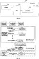
- FIG. 2 is a schematic diagram of a method for probing a channel signal to noise ratio of each subcarrier in the relevant art.
- a predefined probe signal is generated at and transmitted from a transmitting end, and the signal to noise ratio of each subcarrier is obtained by comparing an original probe signal with the predefined probe signal after it is subjected to channel transmission and receiving end processing; then, based on an important assumption that a signal to noise ratio of a probe signal may feature a signal to noise ratio of an actually transmitted signal, the signal to noise ratio of each subcarrier at the actual transmission stage is directly obtained.
- IEEE 802.16e is a standard provided by the IEEE for wideband wireless metropolitan area network communications, in which an adaptive modulation technique of the applied scalable orthogonal frequency division multiple access determines channel modulation under different channel conditions based on such a method for probing a channel signal to noise ratio.
- EP 2 387 171 A2 relates to a managing access to a shared transmission medium such as upstream transmissions in a content distribution or data network.
- a bandwidth allocation and monitoring method divides available bandwidth on a shared communication medium into a plurality of discrete tones that can be individually allocated to modems on an as-needed basis.
- the effective modulation rate that a particular modem can use for each discrete tone is monitored overtime using a schedule of pilot tones transmitted from the modems on different tones at different times.
- the schedule defines representative pilot tones, in which case effective modulation rates for neighboring tones are inferred from a determined effective modulation rate of a pilot tone.
- nonlinearity usually exists in an actual system.
- the nonlinearity will make a signal to noise ratio measured in a probing stage unable to accurately feature a signal to noise ratio at an actual transmission stage, and transmission configuration obtained based on the inaccurate signal to noise ratio at the probing stage is also not optimal, influence of which being directly embodied by great increase of a probability of out-of-range of a bit error at the actual transmission stage, thereby greatly affecting stability of the transmission system.
- a method counteracting such deviation in an existing system and application is at a cost of sacrificing efficiency of the system, artificially preserving sufficient performance margins.
- the method of artificially preserving sufficient performance margins will obviously applicable no longer.
- Embodiments of the present disclosure provide a signal transmission apparatus and multicarrier communication system, with an aim of not only reducing deviation of a signal to noise ratio probed in the last time of recursion from a signal to noise ratio at an actual transmission stage and improving accuracy of a nonlinear channel signal to noise ratio probing, but also accurately predicting transmission performance at the actual transmission stage according to a correct signal to noise ratio and recommended signal configuration, so as to provide support to flexible system adaptive control reception, thereby ensuring reliability and stability of the communication system.
- a signal transmission apparatus including:
- a signal transmission apparatus including:
- a multicarrier communication system including:
- An advantage of the embodiments of the present disclosure exists in that by probing channel SNR based on multiple times of recursion, not only reducing deviation of a signal to noise ratio probed in the last time of recursion from a signal to noise ratio at an actual transmission stage and improving accuracy of a nonlinear channel signal to noise ratio probing, but also accurately predicting transmission performance at the actual transmission stage according to a correct signal to noise ratio and recommended signal configuration, so as to provide support to flexible system adaptive control reception, thereby ensuring reliability and stability of the communication system.
- FIG. 3 is a schematic diagram of a structure of the signal transmission apparatus of the embodiment of the present disclosure. As shown in FIG 3 , the signal transmission apparatus 300 includes:
- the characteristics of the recommended signal configuration are one or more of the following: a power allocation characteristic, a bit allocation characteristic, and a bandwidth characteristic.
- the above characteristics wholly or partially embody a contribution of a nonlinear noise of a signal at an actual transmission stage to the signal to noise ratio, thereby being more advantageous to reducing deviation of a signal to noise ratio probed at latter time of recursion from a signal to noise ratio at the actual transmission stage.
- the power allocation characteristic may be that power allocation of each subcarrier also satisfies a recommended configured power allocation relationship
- the bit allocation characteristic may be a modulation format of each subcarrier, etc., and this embodiment is not limited thereto.
- configuration of a predetermined probe signal probed for a first time may be determined by using the relevant art, and this embodiment is not limited thereto.
- the number of times of the signal to noise ratio probing may be any predetermined value, and this embodiment is not limited thereto.
- the transmission signal configuration may include such configuration information of a signal as power allocation, bit allocation, and a bandwidth, etc.
- the transmission performance may include determining such performance of the signal as a bit error rate, and a Q value margin, etc., and this embodiment is not limited thereto.
- the signal transmission apparatus may further include a preprocessing unit (not shown) configured to preprocess the probe signal received by the first receiving unit 301, and the first processing unit 302 is configured to probe the signal to noise ratio according to the probe signal processed by the preprocessing unit; the preprocessing may include equalization processing, etc., and this embodiment is not limited thereto.
- a preprocessing unit (not shown) configured to preprocess the probe signal received by the first receiving unit 301, and the first processing unit 302 is configured to probe the signal to noise ratio according to the probe signal processed by the preprocessing unit; the preprocessing may include equalization processing, etc., and this embodiment is not limited thereto.
- the used probe signals are different, that is, the nonlinear noise probed after multiple times of recursion are more close to the nonlinear noise at the actual transmission stage, thereby improving accuracy of probing nonlinear channel signal to noise ratio.
- optimal transmission signal configuration and signal transmission performance may be obtained, and finally actually transmitted signals with optimal configuration are generated.
- the actually transmitted signals with optimal configuration not only contain optimal signal configuration of transmission data provided at the channel probing stage, but also contain configuration information on controllable modules according to the predicted transmission performance, such as an adaptive module, etc., thereby ensuring reliability and stability of the communication system.
- FIG. 4 is a schematic diagram of a structure of the signal transmission apparatus of the embodiment of the present disclosure.
- the signal transmission apparatus 400 includes a first receiving unit 401, a first processing unit 402, a first determining unit 403 and a first transmitting unit 404, implementations of which being identical to those of the first receiving unit 301, the first processing unit 302, the first determining unit 303 and the first transmitting unit 304 in Embodiment 1, and being not going to be described herein any further.
- the signal transmission apparatus 400 may further include:
- the first determining unit 403 further includes:
- the second determining unit 4031 is configured to use a channel signal to noise ratio probed after the number of times of signal to noise ratio probing by the first processing unit 402 reaches the first threshold value as a final channel signal to noise ratio, and determine the transmission signal configuration by using the final channel signal to noise ratio to perform adaptive modulation allocation.
- a method for obtaining the transmission signal configuration by using the signal to noise ratio to perform adaptive modulation allocation may use the relevant art.
- a target of a bit error rate of the adaptive modulation allocation is set to be 1e-3, and an allocation criterion is that a rate is optimal, etc.; and furthermore, the first threshold value may be arbitrarily set as demanded, and what described here is illustrative only, and this embodiment is not limited thereto.
- FIG. 5 is a schematic diagram of an implementation of the third determining unit 4032 of the embodiment of the present disclosure. As shown in FIG. 5 , the third determining unit 4032 may include:
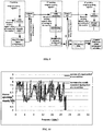
- FIG. 6 is a schematic diagram of a structure of the DMT transmission system.
- the number of subcarriers in the DMT transmission system may be set as demanded, a digital signal sampling rate is 64 Gsa/s, and a laser is a low-side device, hence there exists relatively large nonlinearity.
- FIG. 7 is a schematic diagram of comparison of a curve of a signal transmission method in the relevant art and a curve of a signal to noise ratio at an actual transmission stage relevant art.
- the curve of the signal to noise ratio probed by using the relevant art is higher than the curve of the actually transmitted signal to noise ratio by 2 dB, that is, the channel signal to noise ratio is over-estimated in the relevant art, which may result in that actually transmitted bit error performance is degraded and even result in transmission failure, and such deviation of signal to noise ratios is originated from that spectral characteristics of transmission signals at the probing stage and at the actual transmission stage are different, hence the nonlinear noises are different.
- FIG. 8 is a schematic diagram of comparison of power spectra of a predetermined probe signal in the relevant art and power spectra of an actually transmitted signal relevant art. As shown in FIG. 8 , as a spectral characteristics of the actually transmitted signal is determined by a bit power allocation algorithm, in which such operations as abandoning subcarriers and optimizing power, etc., are contained, the spectrum of the actually transmitted signal is obvious different from that of the predetermined probe signal.
- FIG. 9 is a schematic diagram of a method for probing a channel signal to noise ratio of each subcarrier based on multiple times of recursion of the embodiment of the present disclosure.
- predetermined probe signal configuration of the first time of probing is a pseudo-random sequence of a known data source
- power of all subcarriers is identical and their modulation formats are QPSK
- a probe signal of the first time of recursion is identical to the probe signal probed by using an existing method
- recommended signal configuration 1 is given according to a signal to noise ratio 1 obtained in the first time of probing, and all or part of characteristics are selected according to configuration 1, and a probe signal 2 is generated; for example, available subcarriers of the second time of probe signal adopt available subcarriers of the recommended signal configuration probed at the first time, power allocation of the subcarriers satisfying a power allocation relationship of the
- FIG. 10 is a schematic diagram of comparison of a spectrum of a signal and a spectrum of an actually transmitted signal probed at the second time of Embodiment 2 of the present disclosure
- FIG. 11 is a schematic diagram of comparison of a curve of the signal to noise ratio probed in two times of recursion and a curve of the actually transmitted signal to noise ratio of the embodiment of the present disclosure.
- the signal to noise ratio at the actual transmission stage may still be accurately probed.
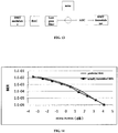
- FIG. 12 is a schematic diagram of comparison of a transmission signal modulation format obtained by taking the signal to noise ratio probed by using the probing method in the relevant art as input and a transmission signal modulation format obtained by taking the signal to noise ratio probed by using the embodiment of the present disclosure as input. As shown in FIG.
- the recommended modulation bits of the signal to noise ratio probed based on the embodiment of the present disclosure are less than 1 bit in most subcarriers than the recommended modulation bits of the signal to noise ratio of the existing method, this avoids a risk of possible degradation of the bit error rate of the actual transmission, even transmission failure, of the existing method, and ensures the reliability and stability of the communication system.
- the transmission signal configuration determining the signal modulation formats of the embodiment of the present disclosure is illustrated above only, and furthermore, for example, the relevant art may be adopted for determining power allocation configuration or bandwidth configuration of a signal, which shall not be described herein any further.
- the accurate signal to noise ratio and the optimal transmission signal configuration probed based on the signal transmission apparatus of the embodiment of the present disclosure are able to improve performance of the signal transmission.
- symbols of the signal configuration at the actual transmission stage are those shown in Table 1 below; where, n is an index of a subcarrier, and N is the number of available subcarriers.
- Table 1 Meaning Values are expressed by variables as Unit Power of each subcarrier P1, P2,..., Pn,... watt Modulation bits of each subcarrier b1, b2,..., bn,... bit Probed signal to noise ratio of each subcarrier g1, g2,..., gn,... 1 Symbol error rate target SERtrgt 1
- the first calculating unit 501 is configured to calculate owned signal to noise ratio, denoted by SNRmargin, under given power allocation and bit allocation according to the probed signal to noise ratio and symbol error rate target of each subcarrier by using Formula (1):
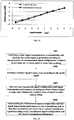
- FIG. 13 is a systematic block diagram of DMT simulation of the linear channel of the embodiment of the present disclosure, which is used to explain performance of the above method for predicting the bit error rate.
- the number of the subcarriers in the DMT system may be set as demanded, a data sampling rate is 61 Gsa/s, an actual transmission capacity is fixed as 107 Gbps, and the symbol error rate target is 1e-3.
- FIGs. 14 and 15 are schematic diagrams of comparison of predicted transmission performance and actually transmitted transmission performance of the embodiment of the present disclosure described by taking the DMT system as an example. As shown in FIGs. 14 and 15 , the predicted bit error rate and Q value margin are extremely close to the actually transmitted bit error rate and Q value margin, that is, with the above embodiment of the present disclosure, accuracy of the prediction of performance of the actual transmission may be improved based on the probed accurate signal to noise ratio and optimal actually transmitted signal configuration.
- An embodiment of the present disclosure provides a signal transmission method, corresponding to the signal transmission apparatus in Embodiment 1 or 2, with identical contents being not going to be described herein any further.
- FIG. 16 is a flowchart of the signal transmission method of the embodiment of the present disclosure. As shown in FIG. 16 , the signal transmission method includes:
- the used probe signals are different, that is, the nonlinear noise probed after multiple times of recursion are more close to the nonlinear noise at the actual transmission stage, thereby improving accuracy of probing nonlinear channel signal to noise ratio.
- optimal transmission signal configuration and signal transmission performance may be obtained, and finally actually transmitted signals with optimal configuration are generated.
- the actually transmitted signals with optimal configuration not only contain optimal signal configuration of transmission data provided at the channel probing stage, but also contain configuration information on controllable modules according to the predicted transmission performance, such as an adaptive module, etc., thereby ensuring reliability and stability of the communication system.
- the characteristics of the recommended signal configuration are one or more of the following: a power allocation characteristic, a bit allocation characteristic, and a bandwidth characteristic.
- the above characteristics wholly or partially embody a contribution of a nonlinear noise of a signal at an actual transmission stage to the signal to noise ratio, thereby being more advantageous to reducing deviation of a signal to noise ratio probed at latter time of recursion from a signal to noise ratio at the actual transmission stage.
- configuration of a predetermined probe signal probed for a first time may be determined by using the relevant art, and this embodiment is not limited thereto.
- the power allocation characteristic may be that power allocation of each subcarrier also satisfies a recommended configured power allocation relationship
- the bit allocation characteristic may be a modulation format of each subcarrier, etc., and this embodiment is not limited thereto.
- configuration of a predetermined probe signal probed for a first time may be determined by using the relevant art, and this embodiment is not limited thereto.
- the number of times of the signal to noise ratio probing may be any predetermined value, and this embodiment is not limited thereto.
- the transmission signal configuration may include such configuration information of a signal as power allocation, bit allocation, and a bandwidth, etc.
- the transmission performance may include determining such performance of the signal as a bit error rate, and a Q value margin, etc., and this embodiment is not limited thereto.
- the signal transmission method may further include (not shown) generating the recommended signal configuration according to a signal to noise ratio obtained in each time of probing, and transmitting the recommended signal configuration to the transmitting end, so that the transmitting end generates and transmits the probe signal according to the characteristics of the recommended signal configuration.
- the transmission signal configuration is determined according to a finally probed channel signal to noise ratio, and the signal transmission performance is determined according to the finally probed channel signal to noise ratio and the transmission signal configuration.
- the finally probed channel signal to noise ratio may be used to perform adaptive modulation allocation to determine the transmission signal configuration, and a particular implementation is similar to that in Embodiment 2, and shall not be described herein any further.
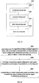
- FIG. 17 is a flowchart of an implementation of step 1603 of Embodiment 3 of the present disclosure in which the signal transmission performance is determined according to a finally probed channel signal to noise ratio and the transmission signal configuration.
- the method may include:
- steps 1701-1703 are identical to those of the first calculating unit 501, the second calculating unit 502 and the third calculating unit 503 in Embodiment 2, the contents of which being incorporated herein, and being not going to be described herein any further.
- an extra signal to noise ratio margin value of the bit error rate is calculated according to the difference between the definitions of the symbol error rate and the bit error rate, thereby improving accuracy of prediction of the transmission performance.
- the signal transmission method may further include a preprocessing step (not shown), in which the probe signal is preprocessed;
- the preprocessing may include equalization processing, etc., and this embodiment is not limited thereto.
- Embodiment 4 of the present disclosure provides a receiver, including the signal transmission apparatus as described in Embodiment 1 or 2, with identical contents being not going to be described herein any further.
- Embodiment 3 may be referred to for a particular implementation of the receiver, with repeated parts being not going to be described herein any further.
- FIG. 18 is a block diagram of a systematic structure of the receiver 1800 of the embodiment of the present disclosure.
- the receiver 1800 may include a central processing unit 1801 and a memory 1840, the memory 1840 being coupled to the central processing unit 1801.
- this figure is illustrative only, and other types of structures may also be used, so as to supplement or replace this structure and achieve telecommunications function or other functions.
- the functions of the signal transmission apparatus may be integrated into the central processing unit 1801.
- the central processing unit 1801 may be configured to: receive a probe signal transmitted by a transmitting end; the probe signal is generated according to characteristics of recommended signal configuration obtained by previous one or more times of signal to noise ratio probing; probe a channel signal to noise ratio of according to the probe signal; determine transmission signal configuration and signal transmission performance according to a final channel signal to noise ratio obtained by multiple times of signal to noise ratio probing; and transmit the transmission signal configuration and signal transmission performance to the transmitting end, so that the transmitting end transmits an actual transmission signal according to the transmission signal configuration and the signal transmission performance.
- the central processing unit 1801 may further be configured to be that the characteristics of the recommended signal configuration are one or more of the following: a power allocation characteristic, a bit allocation characteristic, and a bandwidth characteristic.
- the central processing unit 1801 may further be configured to: generate the recommended signal configuration according to a channel signal to noise ratio obtained in each time of probing; and transmit the recommended signal configuration to the transmitting end, so that the transmitting end generates and transmits the probe signal according to the characteristics of the recommended signal configuration.
- the central processing unit 1801 may further be configured to: determine the transmission signal configuration according to a finally probed channel signal to noise ratio after the number of times of signal to noise ratio probing reaches a first threshold value; and determine the signal transmission performance according to the finally probed channel signal to noise ratio and the determined transmission signal configuration.
- the central processing unit 1801 may further be configured to: determine the transmission signal configuration by using the finally probed channel signal to noise ratio to perform adaptive modulation allocation after the number of times of signal to noise ratio probing reaches the first threshold value.
- the central processing unit 1801 may further be configured to: calculate a first signal to noise ratio margin value under given power allocation and bit allocation according to a signal to noise ratio and a symbol error rate target on each subcarrier; calculate a second signal to noise ratio margin value for a bit error rate according to a difference between definitions of a symbol error rate and a bit error rate; and calculate the signal transmission performance according to the first signal to noise ratio margin value the second signal to noise ratio margin value.
- the signal transmission apparatus and the central processing unit 1801 may be configured separately.
- the signal transmission apparatus may be configured as a chip connected to the central processing unit 1801, with its functions being realized under control of the central processing unit.
- the receiver 1800 may further include a transceiver 1820, and an antenna 1830, etc. It should be noted that the receiver 1800 does not necessarily include all the parts shown in FIG. 18 . And furthermore, the receiver 1800 may include components not shown in FIG. 18 , and the relevant art may be referred to.
- the central processing unit 1801 is sometimes referred to as a controller or control, and may include a microprocessor or other processor devices and/or logic devices.
- the memory 1840 may be, for example, one or more of a buffer memory, a flash memory, a hard drive, a mobile medium, a volatile memory, a nonvolatile memory, or other suitable devices. It may store SNRs of multiple times of recursion and signal configuration, and may further store programs executing related information. And the central processing unit 100 may execute the programs stored in the memory 1840, so as to realize information storage or processing, etc. Functions of other parts are similar to those of the relevant art, which shall not be described herein any further. The parts of the receiver 1800 may be realized by specific hardware, firmware, software, or any combination thereof, without departing from the scope of the present disclosure.
- the used probe signals are different, that is, the nonlinear noise probed after multiple times of recursion are more close to the nonlinear noise at the actual transmission stage, thereby improving accuracy of probing nonlinear channel signal to noise ratio.
- optimal transmission signal configuration and signal transmission performance may be obtained, and finally actually transmitted signals with optimal configuration are generated.
- the actually transmitted signals with optimal configuration not only contain optimal signal configuration of transmission data provided at the channel probing stage, but also contain configuration information on controllable modules according to the predicted transmission performance, such as an adaptive module, etc., thereby ensuring reliability and stability of the communication system.
- Embodiment 5 of the present disclosure provides a signal transmission apparatus.
- FIG. 19 is a schematic diagram of a structure of the signal transmission apparatus of the embodiment of the present disclosure. As shown in FIG. 19 , the signal transmission apparatus 1900 includes:
- the characteristics of the recommended signal configuration are one or more of the following: a power allocation characteristic, a bit allocation characteristic, and a bandwidth characteristic.
- the above characteristics wholly or partially embody a contribution of a nonlinear noise of a signal at an actual transmission stage to the signal to noise ratio, thereby being more advantageous to reducing deviation of a signal to noise ratio probed at latter time of recursion from a signal to noise ratio at the actual transmission stage.
- configuration of a predetermined probe signal probed for a first time may be determined by using the relevant art, and this embodiment is not limited thereto.
- the power allocation characteristic may be that power allocation of each subcarrier also satisfies a recommended configured power allocation relationship
- the bit allocation characteristic may be a modulation format of each subcarrier, etc., that is, the probe signal used for signal to noise ratio probing is generated according to the power allocation characteristic, the bit allocation characteristic, and the bandwidth characteristic, and this embodiment is not limited thereto.
- Embodiment 2 may be referred to for a particular implementation of the second processing unit 1901, which shall not be described herein any further.
- the signal transmission apparatus 1900 may further include: a third receiving unit 1904 configured to receive the recommended signal configuration generated according to a channel signal to noise ratio obtained in each time of probing and transmitted by the receiving end.
- the third receiving unit 1904 is optional.
- the used probe signals are different, that is, the nonlinear noise probed after multiple times of recursion are more close to the nonlinear noise at the actual transmission stage, thereby improving accuracy of probing nonlinear channel signal to noise ratio.
- optimal transmission signal configuration and signal transmission performance may be obtained, and finally actually transmitted signals with optimal configuration are generated.
- the actually transmitted signals with optimal configuration not only contain optimal signal configuration of transmission data provided at the channel probing stage, but also contain configuration information on controllable modules according to the predicted transmission performance, such as an adaptive module, etc., thereby ensuring reliability and stability of the communication system.
- Embodiment 6 of the present disclosure provides a signal transmission method, corresponding to the signal transmission apparatus in Embodiment 5, with identical contents being not going to be described herein any further.
- FIG. 20 is a flowchart of the signal transmission method of the embodiment of the present disclosure. As shown in FIG. 20 , the signal transmission method includes:
- the characteristics of the recommended signal configuration are one or more of the following: a power allocation characteristic, a bit allocation characteristic, and a bandwidth characteristic.
- Embodiment 2 may be referred to for a particular implementation, and being not going to be described herein any further.
- the above characteristics wholly or partially embody a contribution of a nonlinear noise of a signal at an actual transmission stage to the signal to noise ratio, thereby being more advantageous to reducing deviation of a signal to noise ratio probed at latter time of recursion from a signal to noise ratio at the actual transmission stage.
- configuration of a predetermined probe signal probed for a first time may be determined by using the relevant art, and this embodiment is not limited thereto.
- Embodiment 2 may be referred to for a particular implementation of step 2001, the contents of which being incorporated herein, and being not going to be described herein any further.
- the signal transmission method may further include: receiving the recommended signal configuration generated according to a channel signal to noise ratio obtained in each time of probing and transmitted by the receiving end. This step is optional.
- the used probe signals are different, that is, the nonlinear noise probed after multiple times of recursion are more close to the nonlinear noise at the actual transmission stage, thereby improving accuracy of probing nonlinear channel signal to noise ratio.
- optimal transmission signal configuration and signal transmission performance may be obtained, and finally actually transmitted signals with optimal configuration are generated.
- the actually transmitted signals with optimal configuration not only contain optimal signal configuration of transmission data provided at the channel probing stage, but also contain configuration information on controllable modules according to the predicted transmission performance, such as an adaptive module, etc., thereby ensuring reliability and stability of the communication system.
- Embodiment 7 of the present disclosure provides a transmitter, including the signal transmission apparatus as described in Embodiment 5, with identical contents being not going to be described herein any further.
- Embodiment 6 may be referred to for a particular implementation of the transmitter, with repeated parts being not going to be described herein any further.
- FIG. 21 is a block diagram of a systematic structure of the transmitter 2100 of the embodiment of the present disclosure.
- the transmitter 2100 may include a central processing unit 2101 and a memory 2140, the memory 2140 being coupled to the central processing unit 2101.
- this figure is illustrative only, and other types of structures may also be used, so as to supplement or replace this structure and achieve telecommunications function or other functions.
- the functions of the signal transmission apparatus may be integrated into the central processing unit 2101.
- the central processing unit 2101 may be configured to: generate a probe signal for probing channel a signal to noise ratio according to characteristics of recommended signal configuration obtained by previous one or more times of signal to noise ratio probing; receive transmission signal configuration and signal transmission performance transmitted by a receiving end; and transmit an actual transmission signal according to the transmission signal configuration and the signal transmission performance.
- the central processing unit 2101 may further be configured to: receive recommended signal configuration generated according to a signal to noise ratio of a channel obtained in each time of detection and transmitted by the receiving end.
- the signal transmission apparatus and the central processing unit 2101 may be configured separately.
- the signal transmission apparatus may be configured as a chip connected to the central processing unit 2101, with its functions being realized under control of the central processing unit.
- the transmitter 2100 may further include a transceiver 2120, and an antenna 2130, etc. It should be noted that the transmitter 2100 does not necessarily include all the parts shown in FIG. 21 . And furthermore, the transmitter 2100 may include components not shown in FIG. 21 , and the relevant art may be referred to.
- the central processing unit 2101 is sometimes referred to as a controller or control, and may include a microprocessor or other processor devices and/or logic devices.
- the memory 2140 may be, for example, one or more of a buffer memory, a flash memory, a hard drive, a mobile medium, a volatile memory, a nonvolatile memory, or other suitable devices. It may store SNRs of multiple times of recursion and signal configuration, and may further store programs executing related information. And the central processing unit 100 may execute the programs stored in the memory 2140, so as to realize information storage or processing, etc. Functions of other parts are similar to those of the relevant art, which shall not be described herein any further. The parts of the transmitter 2100 may be realized by specific hardware, firmware, software, or any combination thereof, without departing from the scope of the present disclosure.
- the used probe signals are different, that is, the nonlinear noise probed after multiple times of recursion are more close to the nonlinear noise at the actual transmission stage, thereby improving accuracy of probing nonlinear channel signal to noise ratio.
- optimal transmission signal configuration and signal transmission performance may be obtained, and finally actually transmitted signals with optimal configuration are generated.
- the actually transmitted signals with optimal configuration not only contain optimal signal configuration of transmission data provided at the channel probing stage, but also contain configuration information on controllable modules according to the predicted transmission performance, such as an adaptive module, etc., thereby ensuring reliability and stability of the communication system.
- An embodiment of the present disclosure further provides a multicarrier communication system, including:
- Embodiment 4 may be referred to for an implementation of the receiver, and Embodiment 7 may be referred to for an implementation of the transmitter, with identical contents being not going to be described herein any further.
- FIG. 22 is a schematic diagram of a structure of the multicarrier communication system and the transmission scheme of Embodiment 8 of the present disclosure.
- the transmitter generates the predetermined probe signal, and transmits the signal to the receiver after the signal passes through a communication channel;
- the receiver performs signal processing after receiving the probe signal, compares the processed received signal with the original probe signal subcarrier by subcarrier, obtains a signal to noise ratio 1 through calculation, gives recommended signal configuration 1 according to the signal to noise ratio 1, and feeds the recommended signal configuration 1 back to the transmitter;
- the transmitter receives the configuration 1 and selects all or part of characteristics from the configuration 1, and generates and transmits a new probe signal 2;
- the probe signal 2 passes through the channel and is processed at the receiver, the probe signal 2 after being processed by the receiver is compared with the original probe signal 2 subcarrier by subcarrier, a signal to noise ratio 2 is calculated, recommended signal configuration 2 is given according to the signal to noise ratio 2, and a finally probed channel signal to noise ratio is obtained after multiple times of
- the transmission scheme of the multicarrier communication system provided by the embodiment of the present disclosure, based on the accurate signal to noise ratio probed by multiple times of recursion, actually transmitted signals of optimal configuration are generated, which not only contain optimal signal configuration of transmission data provided at the signal probing stage, but also contain configuration information on controllable modules according to the predicted transmission performance, such as an adaptive module, etc., thereby ensuring reliability and stability of the communication system.
- An embodiment of the present disclosure further provides a computer-readable program, when the program is executed in a receiver, the program enables a computer to carry out the signal transmission method as described in Embodiment 3 in the receiver.
- An embodiment of the present disclosure further provides a storage medium in which a computer readable program is stored, the computer readable program enables a computer to carry out the signal transmission method as described in Embodiment 3 in a receiver.
- An embodiment of the present disclosure further provides a computer-readable program, when the program is executed in a transmitter, the program enables a computer to carry out the signal transmission method as described in Embodiment 6 in the transmitter.
- An embodiment of the present disclosure further provides a storage medium which stores a computer readable program, the computer readable program enables a computer to carry out the signal transmission method as described in Embodiment 6 in a transmitter.
- the above apparatuses and methods of the present disclosure may be implemented by hardware, or by hardware in combination with software.
- the present disclosure relates to such a computer-readable program that when the program is executed by a logic device, the logic device is enabled to carry out the apparatus or components as described above, or to carry out the methods or steps as described above.
- the present disclosure also relates to a storage medium for storing the above program, such as a hard disk, a floppy disk, a CD, a DVD, and a flash memory, etc.
- signal transmission apparatus comprises:
- the signal transmission apparatus according to example 1, wherein the characteristics of the recommended signal configuration are one or more of the following: a power allocation characteristic, a bit allocation characteristic, and a bandwidth characteristic.
- the signal transmission apparatus according to example 3, wherein the signal transmission apparatus further comprises:
- the signal transmission apparatus according to example 1, wherein the first determining unit further comprises:
- the signal transmission apparatus according to example 4, wherein the second determining unit is configured to determine the transmission signal configuration by using the finally probed channel signal to noise ratio to performing adaptive modulation allocation after the number of times of signal to noise ratio probing by the first processing unit reaches the first threshold value.
- the third determining unit further comprises:
- a signal transmission apparatus comprises:
- Supplement 9 The signal transmission apparatus according to supplement 8, wherein the signal transmission apparatus further comprises: a third receiving unit configured to receive the recommended signal configuration generated according to a channel signal to noise ratio obtained in each time of probing and transmitted by the receiving end.
- a multicarrier communication system comprises:
- a signal transmission method includes:
- the signal transmission method according to example 11, wherein the characteristics of the recommended signal configuration are one or more of the following: a power allocation characteristic, a bit allocation characteristic, and a bandwidth characteristic.
- the determining transmission signal configuration and signal transmission performance according to a channel final signal to noise ratio obtained by multiple times of signal to noise ratio probing further includes:
- example 15 the signal transmission method according to example 14, wherein after the number of times of signal to noise ratio probing reaches the first threshold value, the finally probed channel signal to noise ratio is used for performing adaptive modulation allocation to determine the transmission signal configuration.
- the determining the signal transmission performance according to the finally probed channel signal to noise ratio and the transmission signal configuration further includes:
- a signal transmission method includes:
- the signal transmission method further includes: Receiving the recommended signal configuration generated according to a channel signal to noise ratio obtained in each time of probing and transmitted by the receiving end.
- a receiver includes the signal transmission apparatus as described in any one of examples 1-7.
- a transmitter includes the signal transmission apparatus as described in any one of examples 8-9.
- example 22 a computer-readable program, wherein when the program is executed in a transmitter, the program enables a computer to carry out the signal transmission method as described in any one of examples 18-19 in the transmitter.
- example 23 a storage medium in which a computer readable program is stored, wherein the computer readable program enables a computer to carry out the signal transmission method as described in any one of examples 11-17 in a receiver.
Landscapes
- Engineering & Computer Science (AREA)
- Signal Processing (AREA)
- Computer Networks & Wireless Communication (AREA)
- Quality & Reliability (AREA)
- Physics & Mathematics (AREA)
- Electromagnetism (AREA)
- Power Engineering (AREA)
- Mobile Radio Communication Systems (AREA)
- Digital Transmission Methods That Use Modulated Carrier Waves (AREA)
Description
- The present disclosure relates to the field of communications, and in particular to a signal transmission apparatus and multicarrier communication system.
- A multicarrier communication system is a communication system based on multicarrier modulation, which is widely used in wireless and access networks at present due to its advantages, such as high transmission rate, high spectral efficiency, and multipath and frequency domain fading proof, and to which wide attention is paid and studied as being taken as an important solution for future higher speed and complex network communications.
- A channel signal to noise ratio (SNR) probing technique is a necessary technique important to the multicarrier communication system.
FIG. 1 is a schematic diagram of a channel probing stage in the multicarrier communication system. As shown inFIG. 1 , its main function is that before actual transmission, channel information is collected by using a probe signal, so as to estimate signal to noise ratios of subcarriers of a channel at the actual transmission stage; then modulation formats and power allocation adopted at the actual transmission stage are selected for available subcarriers in an adaptive optimization or direct designation manner according to recommended actual transmission signal configuration selected according to the signal to noise ratios, such as abandoning channel subcarriers of bad conditions, so as to improve a transmission rate or performance. It can be seen that before actual transmission, obtaining a signal to noise ratio consistent with that in the actual transmission by using the probe signal is key to success of the transmission. This is because that first, optimal transmission configuration can be obtained and transmission efficiency can be maximized only when a correct channel signal to noise ratio in the actual transmission is obtained; and second, the transmission performance can be accurately estimated and services can be provided to design of the system only when the signal to noise ratio in the actual transmission is correctly obtained before the actual transmission, such as avoiding invalid transmission unsatisfying traffic demands, etc. - Currently, methods for probing a channel signal to noise ratio of each subcarrier are relatively simple and direct.
FIG. 2 is a schematic diagram of a method for probing a
channel signal to noise ratio of each subcarrier in the relevant art. As shown inFIG. 2 , a predefined probe signal is generated at and transmitted from a transmitting end, and the signal to noise ratio of each subcarrier is obtained by comparing an original probe signal with the predefined probe signal after it is subjected to channel transmission and receiving end processing; then, based on an important assumption that a signal to noise ratio of a probe signal may feature a signal to noise ratio of an actually transmitted signal, the signal to noise ratio of each subcarrier at the actual transmission stage is directly obtained. For example, IEEE 802.16e is a standard provided by the IEEE for wideband wireless metropolitan area network communications, in which an adaptive modulation technique of the applied scalable orthogonal frequency division multiple access determines channel modulation under different channel conditions based on such a method for probing a channel signal to noise ratio. -
EP 2 387 171 A2 - ANDRE NUNO SEQUEIRA ET AL, "Equalization techniques for high-speed OFDM-based access systems using direct modulation and direct detection", 2013 15TH INTERNATIONAL CONFERENCE ON TRANSPARENT OPTICAL NETWORKS (ICTON), IEEE, doi:10.1109/ICTON.2013.6602971, ISSN 2161-2056, (20130623), pages 1 - 6 [retrieved on 2013-09-17] relates to digital pre-distortion and equalization approaches for OFDM-based access systems, wherein these techniques accommodate for linear and nonlinear channel response. An adaptive bit-and-power loading algorithm suitable for laboratory use is proposed that converges quickly while efficiently adapting an OFDM signal to a transmission system. In addition, a nonlinear Volterra equalization scheme is presented that increases system performance even for a system with low sub-carrier to sub-carrier intermixing interferences.PENG LINNING ET AL, "On Bit-Loading for Discrete Multi-Tone Transmission Over Short Range POF Systems", JOURNAL OF LIGHTWAVE TECHNOLOGY, IEEE SERVICE CENTER, NEW YORK, NY, US, vol. 31, no. 24, doi:10.1109/JLT.2013.2290811, ISSN 0733-8724, (20131201), pages 4155 - 4165, (20131202), [retrieved on 2013-12-02] relates to a novel bit-loading approach for discrete multi-tone transmission over short range polymer optical fiber systems, which provides a better signal-to-noise ratio. From the extracted signal-to-noise ratio table of quadrature amplitude modulation for different desired bit error rates, a new linear approximation expression is introduced to implement bit-loading for discrete multi-tone systems. Based on water-filling concept, the performance bounds and optimal power allocations for the classical and the proposed bit-loading algorithms in Gaussian low-pass channel models are derived. Consequently, introducing the measured channel parameters of step-index (SI)-POF channels with different transmission distances, the theoretical performance bounds are computed and the practical transmission rates are simulated. The linear approximation expression based bit-loading outperforms the modulation gap based bit-loading in discrete multi-tone transmission systems over different transmission distances.
- Documents advantageous to the understanding of the present disclosure and conventional technologies are listed below.
- Reference 1: John A.C. Bingham, ADSL, VDSL, and Multicarrier Modulation, 5th chapter, 2000; and
- Reference 2: IEEE P802.16e, IEEE standard for local and metropolitan area networks, 2005.
- It should be noted that the above description of the background art is merely provided for clear and complete explanation of the present disclosure and for easy understanding by those skilled in the art. And it should not be understood that the above technical solution is known to those skilled in the art as it is described in the background art of the present disclosure.
- However, it was found by the inventors that in the above relevant art, when a channel
is linear, the above assumption is tenable. But for a channel of obvious nonlinearity, as bandwidths and power spectra, etc., of a probe signal and an actually transmitted signal, are different, their signal to noise ratios are also different, hence, deviation will occur in the above assumption. - Being limited to hardware process and cost, nonlinearity usually exists in an actual system. The nonlinearity will make a signal to noise ratio measured in a probing stage unable to accurately feature a signal to noise ratio at an actual transmission stage, and transmission configuration obtained based on the inaccurate signal to noise ratio at the probing stage is also not optimal, influence of which being directly embodied by great increase of a probability of out-of-range of a bit error at the actual transmission stage, thereby greatly affecting stability of the transmission system. A method counteracting such deviation in an existing system and application is at a cost of sacrificing efficiency of the system, artificially preserving sufficient performance margins. However, for a future communication application of a high rate, a high density and a low cost, the method of artificially preserving sufficient performance margins will obviously applicable no longer.
- Embodiments of the present disclosure provide a signal transmission apparatus and multicarrier communication system, with an aim of not only reducing deviation of a signal to noise ratio probed in the last time of recursion from a signal to noise ratio at an actual transmission stage and improving accuracy of a nonlinear channel signal to noise ratio probing, but also accurately predicting transmission performance at the actual transmission stage according to a correct signal to noise ratio and recommended signal configuration, so as to provide support to flexible system adaptive control reception, thereby ensuring reliability and stability of the communication system.
- The present invention is defined in the appended claims. According to an aspect of the embodiments of the present disclosure, there is provided a signal transmission apparatus, including:
- a first receiving unit configured to receive a probe signal transmitted by a transmitting end; wherein, the probe signal is generated according to characteristics of recommended signal configuration obtained by previous one or more times of signal to noise ratio probing;
- a first processing unit configured to probe a channel signal to noise ratio according to the probe signal;
- a first determining unit configured to determine transmission signal configuration and signal transmission performance according to a final channel signal to noise ratio obtained by multiple times of signal to noise ratio probing; and
- a first transmitting unit configured to transmit the transmission signal configuration and the signal transmission performance to the transmitting end, so that the transmitting end transmits an actual transmission signal according to the transmission signal configuration and the signal transmission performance.
- According to another aspect of the embodiments of the present disclosure, there is provided a signal transmission apparatus, including:
- a second processing unit configured to generate a probe signal for probing a channel signal to noise ratio according to characteristics of recommended signal configuration obtained by previous one or more times of signal to noise ratio probing;
- a second receiving unit configured to receive transmission signal configuration and signal transmission performance transmitted by a receiving end; and
- a third transmitting unit configured to transmit an actual transmission signal according to the transmission signal configuration and the signal transmission performance.
- According to a further aspect of the embodiments of the present disclosure, there is provided a multicarrier communication system, including:
- a receiver configured to receive a probe signal transmitted by a transmitter, probe a channel signal to noise ratio according to the probe signal, determine transmission signal configuration and signal transmission performance according to a final channel signal to noise ratio obtained by multiple times of signal to noise ratio probing, and transmit the transmission signal configuration and the signal transmission performance to the transmitter; and
- the transmitter configured to generate and transmit the probe signal, the probe signal being generated according to characteristics of recommended signal configuration obtained by previous one or more times of signal to noise ratio probing, receive the transmission signal configuration and the signal transmission performance transmitted by the receiver, and transmit an actual transmission signal according to the transmission signal configuration and the signal transmission performance.
- An advantage of the embodiments of the present disclosure exists in that by probing channel SNR based on multiple times of recursion, not only reducing deviation of a signal to noise ratio probed in the last time of recursion from a signal to noise ratio at an actual transmission stage and improving accuracy of a nonlinear channel signal to noise ratio probing, but also accurately predicting transmission performance at the actual transmission stage according to a correct signal to noise ratio and recommended signal configuration, so as to provide support to flexible system adaptive control reception, thereby ensuring reliability and stability of the communication system.
- With reference to the following description and drawings, the particular embodiments of the present disclosure are disclosed in detail, and the principle of the present disclosure and the manners of use are indicated. It should be understood that the scope of the embodiments of the present disclosure is not limited thereto. The embodiments of the present disclosure contain many alternations, modifications and equivalents within the scope of the terms of the appended claims.
- Features that are described and/or illustrated with respect to one embodiment may be used in the same way or in a similar way in one or more other embodiments and/or in combination with or instead of the features of the other embodiments.
- It should be emphasized that the term "comprise/include" when used in this specification is taken to specify the presence of stated features, integers, steps or components but does not preclude the presence or addition of one or more other features, integers, steps, components or groups thereof.
- Many aspects of the disclosure can be better understood with reference to the following drawings. The components in the drawings are not necessarily to scale, emphasis instead being placed upon clearly illustrating the principles of the present disclosure. To facilitate illustrating and describing some parts of the disclosure, corresponding portions of the drawings may be exaggerated in size.
- Elements and features depicted in one drawing or embodiment of the disclosure may be combined with elements and features depicted in one or more additional drawings or embodiments. Moreover, in the drawings, like reference numerals designate corresponding parts throughout the several views and may be used to designate like or similar parts in more than one embodiments.
-
FIG. 1 is a schematic diagram of a channel probing stage in the multicarrier communication system; -
FIG. 2 is a schematic diagram of a method for probing a channel signal to noise ratio of each subcarrier in the relevant art; -
FIG. 3 is a schematic diagram of a structure of the signal transmission apparatus ofEmbodiment 1 of the present disclosure; -
FIG. 4 is a schematic diagram of a structure of the signal transmission apparatus ofEmbodiment 2 of the present disclosure; -
FIG. 5 is a schematic diagram of a structure of the third determiningunit 4032 ofEmbodiment 2 of the present disclosure; -
FIG. 6 is a schematic diagram of a structure of the DMT transmission system of AMENDMENTS FOR THE PROSECUTION IN THE EPOREGIONAL PHASE Embodiment 2 of the present disclosure; -
FIG. 7 is a schematic diagram of comparison of a curve of signal to noise ratio of a signal transmission method in the relevant art and a curve of a signal to noise ratio at an actual transmission stage relevant art; -
FIG. 8 is a schematic diagram of comparison of power spectra of a predetermined probe signal in the relevant art and power spectra of an actually transmitted signal relevant art; -
FIG. 9 is a schematic diagram of a method for probing a channel signal to noise ratio of each subcarrier based on multiple times of recursion of an embodiment of the present disclosure; -
FIG. 10 is a schematic diagram of comparison of a spectrum of a signal and a spectrum of an actually transmitted signal probed at a second time ofEmbodiment 2 of the present disclosure; -
FIG. 11 is a schematic diagram of comparison of a curve of the signal to noise ratio probed in two times of recursion and a curve of the actually transmitted signal to noise ratio ofEmbodiment 2 of the present disclosure; -
FIG. 12 is a schematic diagram of comparison of a transmission signal modulation format obtained by taking the signal to noise ratio probed by using the probing method in the relevant art as input and a transmission signal modulation format obtained by taking the signal to noise ratio probed by using the embodiment of the present disclosure as input; -
FIG. 13 is a schematic diagram of a structure of the DMT transmission system ofEmbodiment 2 of the present disclosure; -
FIG. 14 is a schematic diagram of comparison of predicted transmission performance and actually transmitted transmission performance ofEmbodiment 2 of the present disclosure; -
FIG. 15 is a schematic diagram of comparison of predicted transmission performance and actually transmitted transmission performance ofEmbodiment 2 of the present disclosure; -
FIG. 16 is a flowchart of the signal transmission method ofEmbodiment 3 of the present disclosure; -
FIG. 17 is a flowchart of an implementation ofstep 1603 ofEmbodiment 3 of the present disclosure; -
FIG. 18 is a schematic diagram of a structure of the receiver ofEmbodiment 4 of the present disclosure; -
FIG. 19 is a schematic diagram of a structure of the signal transmission apparatus ofEmbodiment 5 of the present disclosure; -
FIG. 20 is a flowchart of the signal transmission method ofEmbodiment 6 of the present disclosure; -
FIG. 21 is a schematic diagram of a structure of the transmitter ofEmbodiment 7 of the present disclosure; and -
FIG. 22 is a schematic diagram of a structure of the multicarrier communication system and the transmission scheme ofEmbodiment 8 of the present disclosure. - These and further aspects and features of the present disclosure will be apparent with reference to the following description and attached drawings. In the description and drawings, particular embodiments of the disclosure have been disclosed in detail as being indicative of some of the ways in which the principles of the disclosure may be employed, but it is understood that the disclosure is not limited correspondingly in scope. Rather, the disclosure includes all changes, modifications and equivalents coming within the terms of the appended claims.
- An embodiment of the present disclosure provides a signal transmission apparatus.
FIG. 3 is a schematic diagram of a structure of the signal transmission apparatus of the embodiment of the present disclosure. As shown inFIG 3 , thesignal transmission apparatus 300 includes: - a
first receiving unit 301 configured to receive a probe signal transmitted by a transmitting end; the probe signal is generated according to characteristics of recommended signal configuration obtained by previous one or more times of signal to noise ratio probing; - a
first processing unit 302 configured to probe a channel signal to noise ratio according to the probe signal; - a first determining
unit 303 configured to determine transmission signal configuration and signal transmission performance according to a final channel signal to noise ratio obtained by multiple times of signal to noise ratio probing; and - a
first transmitting unit 304 configured to transmit the transmission signal configuration and the signal transmission performance to the transmitting end, so that the transmitting end transmits an actual transmission signal according to the transmission signal configuration and the signal transmission performance. - In this embodiment, the characteristics of the recommended signal configuration are one or more of the following: a power allocation characteristic, a bit allocation characteristic, and a bandwidth characteristic. The above characteristics wholly or partially embody a contribution of a nonlinear noise of a signal at an actual transmission stage to the signal to noise ratio, thereby being more advantageous to reducing deviation of a signal to noise ratio probed at latter time of recursion from a signal to noise ratio at the actual transmission stage. For example, the power allocation characteristic may be that power allocation of each subcarrier also satisfies a recommended configured power allocation relationship, and the bit allocation characteristic may be a modulation format of each subcarrier, etc., and this embodiment is not limited thereto.
- In this embodiment, configuration of a predetermined probe signal probed for a first time may be determined by using the relevant art, and this embodiment is not limited thereto.
- In this embodiment, the number of times of the signal to noise ratio probing, that is, the number of times of recursion of the signal to noise ratio probing, may be any predetermined value, and this embodiment is not limited thereto.
- In this embodiment, the transmission signal configuration may include such configuration information of a signal as power allocation, bit allocation, and a bandwidth, etc., and the transmission performance may include determining such performance of the signal as a bit error rate, and a Q value margin, etc., and this embodiment is not limited thereto.
- In this embodiment, the signal transmission apparatus may further include a preprocessing unit (not shown) configured to preprocess the probe signal received by the
first receiving unit 301, and thefirst processing unit 302 is configured to probe the signal to noise ratio according to the probe signal processed by the preprocessing unit; the preprocessing may include equalization processing, etc., and this embodiment is not limited thereto. - With the above signal transmission apparatus, in each time of probing a signal to noise ratio, the used probe signals are different, that is, the nonlinear noise probed after multiple times of recursion are more close to the nonlinear noise at the actual transmission stage, thereby improving accuracy of probing nonlinear channel signal to noise ratio. Based on the above accurate signal to noise ratio, optimal transmission signal configuration and signal transmission performance may be obtained, and finally actually transmitted signals with optimal configuration are generated. The actually transmitted signals with optimal configuration not only contain optimal signal configuration of transmission data provided at the channel probing stage, but also contain configuration information on controllable modules according to the predicted transmission performance, such as an adaptive module, etc., thereby ensuring reliability and stability of the communication system.
- An embodiment of the present disclosure provides a signal transmission apparatus.
FIG. 4 is a schematic diagram of a structure of the signal transmission apparatus of the embodiment of the present disclosure. As shown inFIG. 4 , thesignal transmission apparatus 400 includes afirst receiving unit 401, afirst processing unit 402, a first determiningunit 403 and afirst transmitting unit 404, implementations of which being identical to those of thefirst receiving unit 301, thefirst processing unit 302, the first determiningunit 303 and thefirst transmitting unit 304 inEmbodiment 1, and being not going to be described herein any further. - In this embodiment, as shown in
FIG 4 , in order that the transmitting end generates probe signals containing whole or partial characteristics of more actually transmitted signals, and reduces deviation between a signal to noise ratio probed at the latter time of recursion and a signal to noise ratio at the actual transmission stage, thesignal transmission apparatus 400 may further include: - a
first generating unit 405 configured to generate the recommended signal configuration according to a channel signal to noise ratio obtained in each time of probing; and - a
second transmitting unit 406 configured to transmit the recommended signal configuration to the transmitting end, so that the transmitting end generates and transmits the probe signal according to the characteristics of the recommended signal configuration. - In an implementation, the first determining
unit 403 further includes: - a second determining unit 4031 configured to determine the transmission signal configuration according to a finally probed channel signal to noise ratio after the number of times of signal to noise ratio probing by the first processing unit reaches a first threshold value; and
- a third determining
unit 4032 configured to determine the signal transmission performance according to the channel signal to noise ratio finally probed by thefirst processing unit 402 and the transmission signal configuration determined by the second determining unit 4031. - In this embodiment, the second determining unit 4031 is configured to use a channel signal to noise ratio probed after the number of times of signal to noise ratio probing by the
first processing unit 402 reaches the first threshold value as a final channel signal to noise ratio, and determine the transmission signal configuration by using the final channel signal to noise ratio to perform adaptive modulation allocation. - A method for obtaining the transmission signal configuration by using the signal to noise ratio to perform adaptive modulation allocation may use the relevant art. For example, a target of a bit error rate of the adaptive modulation allocation is set to be 1e-3, and an allocation criterion is that a rate is optimal, etc.; and furthermore, the first threshold value may be arbitrarily set as demanded, and what described here is illustrative only, and this embodiment is not limited thereto.
-
FIG. 5 is a schematic diagram of an implementation of the third determiningunit 4032 of the embodiment of the present disclosure. As shown inFIG. 5 , the third determiningunit 4032 may include: - a first calculating
unit 501 configured to calculate a first signal to noise ratio margin value under given power allocation and bit allocation according to a signal to noise ratio and symbol error rate target on each subcarrier; - a
second calculating unit 502 configured to calculate a second signal to noise ratio margin value for a bit error rate according to a difference between definitions of a symbol error rate and a bit error rate; and - a
third calculating unit 503 configured to calculate the signal transmission performance according to the first signal to noise ratio margin value calculated by the first calculatingunit 501 and the second signal to noise ratio margin value calculated by the second calculatingunit 502. - It can be seen from the embodiment of the present disclosure that calculating a extra signal to noise ratio margin value for a bit error rate based according to a difference between definitions of a symbol error rate and a bit error rate, thereby improving accuracy of prediction of the transmission performance.
- The signal transmission apparatus of the embodiment of the present disclosure shall be described below taking an optical discrete multi-tone (DMT) modulation transmission system as an example.
FIG. 6 is a schematic diagram of a structure of the DMT transmission system. The number of subcarriers in the DMT transmission system may be set as demanded, a digital signal sampling rate is 64 Gsa/s, and a laser is a low-side device, hence there exists relatively large nonlinearity. -
FIG. 7 is a schematic diagram of comparison of a curve of a signal transmission method in the relevant art and a curve of a signal to noise ratio at an actual transmission stage relevant art. As shown inFIG. 7 , the curve of the signal to noise ratio probed by using the relevant art is higher than the curve of the actually transmitted signal to noise ratio by 2 dB, that is, the channel signal to noise ratio is over-estimated in the relevant art, which may result in that actually transmitted bit error performance is degraded and even result in transmission failure, and such deviation of signal to noise ratios is originated from that spectral characteristics of transmission signals at the probing stage and at the actual transmission stage are different, hence the nonlinear noises are different. -
FIG. 8 is a schematic diagram of comparison of power spectra of a predetermined probe signal in the relevant art and power spectra of an actually transmitted signal relevant art. As shown inFIG. 8 , as a spectral characteristics of the actually transmitted signal is determined by a bit power allocation algorithm, in which such operations as abandoning subcarriers and optimizing power, etc., are contained, the spectrum of the actually transmitted signal is obvious different from that of the predetermined probe signal. -
FIG. 9 is a schematic diagram of a method for probing a channel signal to noise ratio of each subcarrier based on multiple times of recursion of the embodiment of the present disclosure. With the signal transmission apparatus in the above embodiment, as shown inFIG. 9 , assuming that the predetermined number of times of recursion of probing the signal to noise ratio is 2, predetermined probe signal configuration of the first time of probing is a pseudo-random sequence of a known data source, power of all subcarriers is identical and their modulation formats are QPSK, and a probe signal of the first time of recursion is identical to the probe signal probed by using an existing method, recommendedsignal configuration 1 is given according to a signal tonoise ratio 1 obtained in the first time of probing, and all or part of characteristics are selected according toconfiguration 1, and aprobe signal 2 is generated; for example, available subcarriers of the second time of probe signal adopt available subcarriers of the recommended signal configuration probed at the first time, power allocation of the subcarriers satisfying a power allocation relationship of the recommended configuration, modulation formats of the subcarriers being all QPSK, etc., and signal tonoise ratio 2 is calculated according toprobe signal 2. At this moment, asprobe signal 2 contains all or part of the characteristics of the more actually transmitted signals, signal tonoise ratio 2 is more close to the nonlinear noise at the actual transmission stage than signal tonoise ratio 1, that is, the probing of the signal to noise ratio is more accurate. -
FIG. 10 is a schematic diagram of comparison of a spectrum of a signal and a spectrum of an actually transmitted signal probed at the second time ofEmbodiment 2 of the present disclosure, andFIG. 11 is a schematic diagram of comparison of a curve of the signal to noise ratio probed in two times of recursion and a curve of the actually transmitted signal to noise ratio of the embodiment of the present disclosure. As shown inFIGs. 10 and11 , with the signal transmission apparatus of the above embodiment, in a case of obvious nonlinearity, the signal to noise ratio at the actual transmission stage may still be accurately probed. - Optimal transmission signal configuration is obtained according to the accurate signal to noise ratio obtained based on the signal transmission apparatus of the embodiment of the present disclosure.
FIG. 12 is a schematic diagram of comparison of a transmission signal modulation format obtained by taking the signal to noise ratio probed by using the probing method in the relevant art as input and a transmission signal modulation format obtained by taking the signal to noise ratio probed by using the embodiment of the present disclosure as input. As shown inFIG. 12 , as the signal to noise ratio is accurately estimated, the recommended modulation bits of the signal to noise ratio probed based on the embodiment of the present disclosure are less than 1 bit in most subcarriers than the recommended modulation bits of the signal to noise ratio of the existing method, this avoids a risk of possible degradation of the bit error rate of the actual transmission, even transmission failure, of the existing method, and ensures the reliability and stability of the communication system. The transmission signal configuration determining the signal modulation formats of the embodiment of the present disclosure is illustrated above only, and furthermore, for example, the relevant art may be adopted for determining power allocation configuration or bandwidth configuration of a signal, which shall not be described herein any further. - The accurate signal to noise ratio and the optimal transmission signal configuration probed based on the signal transmission apparatus of the embodiment of the present disclosure are able to improve performance of the signal transmission. For example, symbols of the signal configuration at the actual transmission stage are those shown in Table 1 below; where, n is an index of a subcarrier, and N is the number of available subcarriers.
Table 1 Meaning Values are expressed by variables as Unit Power of each subcarrier P1, P2,..., Pn,... watt Modulation bits of each subcarrier b1, b2,..., bn,... bit Probed signal to noise ratio of each subcarrier g1, g2,..., gn,... 1 Symbol error rate target SERtrgt 1 - Detailed steps for predicting the actual transmission performance are as follows, and it should be noted that the following formulae are implementations of the first calculating
unit 501, the second calculatingunit 502 and the third calculatingunit 503, and this embodiment of the present disclosure is not limited thereto. - First, the first calculating
unit 501 is configured to calculate owned signal to noise ratio, denoted by SNRmargin, under given power allocation and bit allocation according to the probed signal to noise ratio and symbol error rate target of each subcarrier by using Formula (1):
- The
second calculating unit 502 is configured to calculate the extra signal to noise ratio margin of the bit error rate, denoted by addmargin, introduced by the difference between the definitions of the symbol error rate and the bit error rate by using Formula (2):
- And the third calculating
unit 503 is configured to calculate the bit error rate and the Q value margin at the actual transmission stage, denoted respectively by estimateBER and QdBmargin, according to the signal to noise ratio margins calculated by formulae (1) and (2) by using formulae (3) and (4):

-
FIG. 13 is a systematic block diagram of DMT simulation of the linear channel of the embodiment of the present disclosure, which is used to explain performance of the above method for predicting the bit error rate. The number of the subcarriers in the DMT system may be set as demanded, a data sampling rate is 61 Gsa/s, an actual transmission capacity is fixed as 107 Gbps, and the symbol error rate target is 1e-3. -
FIGs. 14 and15 are schematic diagrams of comparison of predicted transmission performance and actually transmitted transmission performance of the embodiment of the present disclosure described by taking the DMT system as an example. As shown inFIGs. 14 and15 , the predicted bit error rate and Q value margin are extremely close to the actually transmitted bit error rate and Q value margin, that is, with the above embodiment of the present disclosure, accuracy of the prediction of performance of the actual transmission may be improved based on the probed accurate signal to noise ratio and optimal actually transmitted signal configuration. - An embodiment of the present disclosure provides a signal transmission method, corresponding to the signal transmission apparatus in
Embodiment -
FIG. 16 is a flowchart of the signal transmission method of the embodiment of the present disclosure. As shown inFIG. 16 , the signal transmission method includes: - step 1601: receiving a probe signal transmitted by a transmitting end; the probe signal is generated according to characteristics of recommended signal configuration obtained by previous one or more signal to noise ratio probing;
- step 1602: probing a channel signal to noise ratio according to the probe signal;
- step 1603: determining transmission signal configuration and signal transmission performance according to a final channel signal to noise ratio obtained by multiple times of signal to noise ratio probing; and
- step 1604: transmitting the transmission signal configuration and the signal transmission performance to the transmitting end, so that the transmitting end transmits an actual transmission signal according to the transmission signal configuration and the signal transmission performance.
- With the above signal transmission method, in each time of probing a signal to noise ratio, the used probe signals are different, that is, the nonlinear noise probed after multiple times of recursion are more close to the nonlinear noise at the actual transmission stage, thereby improving accuracy of probing nonlinear channel signal to noise ratio. Based on the above accurate signal to noise ratio, optimal transmission signal configuration and signal transmission performance may be obtained, and finally actually transmitted signals with optimal configuration are generated. The actually transmitted signals with optimal configuration not only contain optimal signal configuration of transmission data provided at the channel probing stage, but also contain configuration information on controllable modules according to the predicted transmission performance, such as an adaptive module, etc., thereby ensuring reliability and stability of the communication system.
- In this embodiment, the characteristics of the recommended signal configuration are one or more of the following: a power allocation characteristic, a bit allocation characteristic, and a bandwidth characteristic. The above characteristics wholly or partially embody a contribution of a nonlinear noise of a signal at an actual transmission stage to the signal to noise ratio, thereby being more advantageous to reducing deviation of a signal to noise ratio probed at latter time of recursion from a signal to noise ratio at the actual transmission stage. In this embodiment, configuration of a predetermined probe signal probed for a first time may be determined by using the relevant art, and this embodiment is not limited thereto.
- For example, the power allocation characteristic may be that power allocation of each subcarrier also satisfies a recommended configured power allocation relationship, and the bit allocation characteristic may be a modulation format of each subcarrier, etc., and this embodiment is not limited thereto.
- In this embodiment, configuration of a predetermined probe signal probed for a first time may be determined by using the relevant art, and this embodiment is not limited thereto.
- In this embodiment, the number of times of the signal to noise ratio probing, that is, the number of times of recursion of the signal to noise ratio probing, may be any predetermined value, and this embodiment is not limited thereto.
- In this embodiment, the transmission signal configuration may include such configuration information of a signal as power allocation, bit allocation, and a bandwidth, etc., and the transmission performance may include determining such performance of the signal as a bit error rate, and a Q value margin, etc., and this embodiment is not limited thereto.
- In this embodiment, the signal transmission method may further include (not shown) generating the recommended signal configuration according to a signal to noise ratio obtained in each time of probing, and transmitting the recommended signal configuration to the transmitting end, so that the transmitting end generates and transmits the probe signal according to the characteristics of the recommended signal configuration.
- In an implementation, after the number of times of signal to noise ratio probing reaches a first threshold value in
step 1603, the transmission signal configuration is determined according to a finally probed channel signal to noise ratio, and the signal transmission performance is determined according to the finally probed channel signal to noise ratio and the transmission signal configuration. - After the number of times of signal to noise ratio probing reaches the first threshold value, the finally probed channel signal to noise ratio may be used to perform adaptive modulation allocation to determine the transmission signal configuration, and a particular implementation is similar to that in
Embodiment 2, and shall not be described herein any further. -
FIG. 17 is a flowchart of an implementation ofstep 1603 ofEmbodiment 3 of the present disclosure in which the signal transmission performance is determined according to a finally probed channel signal to noise ratio and the transmission signal configuration. The method may include: - step 1701: calculating a first signal to noise ratio margin value under given power allocation and bit allocation according to a signal to noise ratio and a symbol error rate target on each subcarrier;
- step 1702: calculating a second signal to noise ratio margin value for a bit error rate according to a difference between definitions of a symbol error rate and a bit error rate; and
- step 1703: calculating the signal transmission performance according to the first signal to noise ratio margin value and the second signal to noise ratio margin value.
- Particular implementations of steps 1701-1703 are identical to those of the first calculating
unit 501, the second calculatingunit 502 and the third calculatingunit 503 inEmbodiment 2, the contents of which being incorporated herein, and being not going to be described herein any further. - In this embodiment, an extra signal to noise ratio margin value of the bit error rate is calculated according to the difference between the definitions of the symbol error rate and the bit error rate, thereby improving accuracy of prediction of the transmission performance.
- In this embodiment, before
step 1602, the signal transmission method may further include a preprocessing step (not shown), in which the probe signal is preprocessed; The preprocessing may include equalization processing, etc., and this embodiment is not limited thereto. -
Embodiment 4 of the present disclosure provides a receiver, including the signal transmission apparatus as described inEmbodiment - In this embodiment, the method in
Embodiment 3 may be referred to for a particular implementation of the receiver, with repeated parts being not going to be described herein any further. -
FIG. 18 is a block diagram of a systematic structure of thereceiver 1800 of the embodiment of the present disclosure. As shown inFIG. 18 , thereceiver 1800 may include acentral processing unit 1801 and amemory 1840, thememory 1840 being coupled to thecentral processing unit 1801. It should be noted that this figure is illustrative only, and other types of structures may also be used, so as to supplement or replace this structure and achieve telecommunications function or other functions. - In an implementation, the functions of the signal transmission apparatus may be integrated into the
central processing unit 1801. Thecentral processing unit 1801 may be configured to: receive a probe signal transmitted by a transmitting end; the probe signal is generated according to characteristics of recommended signal configuration obtained by previous one or more times of signal to noise ratio probing; probe a channel signal to noise ratio of according to the probe signal; determine transmission signal configuration and signal transmission performance according to a final channel signal to noise ratio obtained by multiple times of signal to noise ratio probing; and transmit the transmission signal configuration and signal transmission performance to the transmitting end, so that the transmitting end transmits an actual transmission signal according to the transmission signal configuration and the signal transmission performance. - The
central processing unit 1801 may further be configured to be that the characteristics of the recommended signal configuration are one or more of the following: a power allocation characteristic, a bit allocation characteristic, and a bandwidth characteristic. - The
central processing unit 1801 may further be configured to: generate the recommended signal configuration according to a channel signal to noise ratio obtained in each time of probing; and transmit the recommended signal configuration to the transmitting end, so that the transmitting end generates and transmits the probe signal according to the characteristics of the recommended signal configuration. - The
central processing unit 1801 may further be configured to: determine the transmission signal configuration according to a finally probed channel signal to noise ratio after the number of times of signal to noise ratio probing reaches a first threshold value; and determine the signal transmission performance according to the finally probed channel signal to noise ratio and the determined transmission signal configuration. - The
central processing unit 1801 may further be configured to: determine the transmission signal configuration by using the finally probed channel signal to noise ratio to perform adaptive modulation allocation after the number of times of signal to noise ratio probing reaches the first threshold value. - The
central processing unit 1801 may further be configured to: calculate a first signal to noise ratio margin value under given power allocation and bit allocation according to a signal to noise ratio and a symbol error rate target on each subcarrier;
calculate a second signal to noise ratio margin value for a bit error rate according to a difference between definitions of a symbol error rate and a bit error rate; and
calculate the signal transmission performance according to the first signal to noise ratio margin value the second signal to noise ratio margin value. - The
central processing unit 1801 may further be configured to be that the second signal to noise ratio margin value is calculated according to a formula as below:
- In another implementation, the signal transmission apparatus and the
central processing unit 1801 may be configured separately. For example, the signal transmission apparatus may be configured as a chip connected to thecentral processing unit 1801, with its functions being realized under control of the central processing unit. - As shown in
FIG. 18 , thereceiver 1800 may further include atransceiver 1820, and anantenna 1830, etc. It should be noted that thereceiver 1800 does not necessarily include all the parts shown inFIG. 18 . And furthermore, thereceiver 1800 may include components not shown inFIG. 18 , and the relevant art may be referred to. - As shown in
FIG. 18 , thecentral processing unit 1801 is sometimes referred to as a controller or control, and may include a microprocessor or other processor devices and/or logic devices. - The
memory 1840 may be, for example, one or more of a buffer memory, a flash memory, a hard drive, a mobile medium, a volatile memory, a nonvolatile memory, or other suitable devices. It may store SNRs of multiple times of recursion and signal configuration, and may further store programs executing related information. And the central processing unit 100 may execute the programs stored in thememory 1840, so as to realize information storage or processing, etc. Functions of other parts are similar to those of the relevant art, which shall not be described herein any further. The parts of thereceiver 1800 may be realized by specific hardware, firmware, software, or any combination thereof, without departing from the scope of the present disclosure. - With the above receiver, in each time of probing a signal to noise ratio, the used probe signals are different, that is, the nonlinear noise probed after multiple times of recursion are more close to the nonlinear noise at the actual transmission stage, thereby improving accuracy of probing nonlinear channel signal to noise ratio. Based on the above accurate signal to noise ratio, optimal transmission signal configuration and signal transmission performance may be obtained, and finally actually transmitted signals with optimal configuration are generated. The actually transmitted signals with optimal configuration not only contain optimal signal configuration of transmission data provided at the channel probing stage, but also contain configuration information on controllable modules according to the predicted transmission performance, such as an adaptive module, etc., thereby ensuring reliability and stability of the communication system.
-
Embodiment 5 of the present disclosure provides a signal transmission apparatus.FIG. 19 is a schematic diagram of a structure of the signal transmission apparatus of the embodiment of the present disclosure. As shown inFIG. 19 , thesignal transmission apparatus 1900 includes: - a
second processing unit 1901 configured to generate a probe signal for probing a channel signal to noise ratio according to characteristics of recommended signal configuration obtained by previous one or more times of signal to noise ratio probing; - a
second receiving unit 1902 configured to receive transmission signal configuration and signal transmission performance transmitted by a receiving end; and - a
third transmitting unit 1903 configured to transmit an actual transmission signal according to the transmission signal configuration and the signal transmission performance. - In this embodiment, the characteristics of the recommended signal configuration are one or more of the following: a power allocation characteristic, a bit allocation characteristic, and a bandwidth characteristic. The above characteristics wholly or partially embody a contribution of a nonlinear noise of a signal at an actual transmission stage to the signal to noise ratio, thereby being more advantageous to reducing deviation of a signal to noise ratio probed at latter time of recursion from a signal to noise ratio at the actual transmission stage. In this embodiment, configuration of a predetermined probe signal probed for a first time may be determined by using the relevant art, and this embodiment is not limited thereto.
- For example, the power allocation characteristic may be that power allocation of each subcarrier also satisfies a recommended configured power allocation relationship, and the bit allocation characteristic may be a modulation format of each subcarrier, etc., that is, the probe signal used for signal to noise ratio probing is generated according to the power allocation characteristic, the bit allocation characteristic, and the bandwidth characteristic, and this embodiment is not limited thereto.
Embodiment 2 may be referred to for a particular implementation of thesecond processing unit 1901, which shall not be described herein any further. - In this embodiment, the
signal transmission apparatus 1900 may further include:
athird receiving unit 1904 configured to receive the recommended signal configuration generated according to a channel signal to noise ratio obtained in each time of probing and transmitted by the receiving end. - In this embodiment, the
third receiving unit 1904 is optional. - With the above signal transmission apparatus, in each time of probing a signal to noise ratio, the used probe signals are different, that is, the nonlinear noise probed after multiple times of recursion are more close to the nonlinear noise at the actual transmission stage, thereby improving accuracy of probing nonlinear channel signal to noise ratio. Based on the above accurate signal to noise ratio, optimal transmission signal configuration and signal transmission performance may be obtained, and finally actually transmitted signals with optimal configuration are generated. The actually transmitted signals with optimal configuration not only contain optimal signal configuration of transmission data provided at the channel probing stage, but also contain configuration information on controllable modules according to the predicted transmission performance, such as an adaptive module, etc., thereby ensuring reliability and stability of the communication system.
-
Embodiment 6 of the present disclosure provides a signal transmission method, corresponding to the signal transmission apparatus inEmbodiment 5, with identical contents being not going to be described herein any further. -
FIG. 20 is a flowchart of the signal transmission method of the embodiment of the present disclosure. As shown inFIG. 20 , the signal transmission method includes: - step 2001: generating a probe signal for probing a channel signal to noise ratio according to characteristics of recommended signal configuration obtained by previous one or more times of signal to noise ratio probing;
- step 2002: receiving transmission signal configuration and signal transmission performance transmitted by a receiving end; and
- step 2003: transmitting an actual transmission signal according to the transmission signal configuration and the signal transmission performance.
- In this embodiment, the characteristics of the recommended signal configuration are one or more of the following: a power allocation characteristic, a bit allocation characteristic, and a bandwidth characteristic.
Embodiment 2 may be referred to for a particular implementation, and being not going to be described herein any further. The above characteristics wholly or partially embody a contribution of a nonlinear noise of a signal at an actual transmission stage to the signal to noise ratio, thereby being more advantageous to reducing deviation of a signal to noise ratio probed at latter time of recursion from a signal to noise ratio at the actual transmission stage. In this embodiment, configuration of a predetermined probe signal probed for a first time may be determined by using the relevant art, and this embodiment is not limited thereto. -
Embodiment 2 may be referred to for a particular implementation ofstep 2001, the contents of which being incorporated herein, and being not going to be described herein any further. - In this embodiment, the signal transmission method may further include: receiving the recommended signal configuration generated according to a channel signal to noise ratio obtained in each time of probing and transmitted by the receiving end. This step is optional.
- With the above signal transmission method, in each time of probing a signal to noise ratio, the used probe signals are different, that is, the nonlinear noise probed after multiple times of recursion are more close to the nonlinear noise at the actual transmission stage, thereby improving accuracy of probing nonlinear channel signal to noise ratio. Based on the above accurate signal to noise ratio, optimal transmission signal configuration and signal transmission performance may be obtained, and finally actually transmitted signals with optimal configuration are generated. The actually transmitted signals with optimal configuration not only contain optimal signal configuration of transmission data provided at the channel probing stage, but also contain configuration information on controllable modules according to the predicted transmission performance, such as an adaptive module, etc., thereby ensuring reliability and stability of the communication system.
-
Embodiment 7 of the present disclosure provides a transmitter, including the signal transmission apparatus as described inEmbodiment 5, with identical contents being not going to be described herein any further. - In this embodiment, the method in
Embodiment 6 may be referred to for a particular implementation of the transmitter, with repeated parts being not going to be described herein any further. -
FIG. 21 is a block diagram of a systematic structure of thetransmitter 2100 of the embodiment of the present disclosure. As shown inFIG. 21 , thetransmitter 2100 may include acentral processing unit 2101 and amemory 2140, thememory 2140 being coupled to thecentral processing unit 2101. It should be noted that this figure is illustrative only, and other types of structures may also be used, so as to supplement or replace this structure and achieve telecommunications function or other functions. - In an implementation, the functions of the signal transmission apparatus may be integrated into the
central processing unit 2101. Thecentral processing unit 2101 may be configured to: generate a probe signal for probing channel a signal to noise ratio according to characteristics of recommended signal configuration obtained by previous one or more times of signal to noise ratio probing; receive transmission signal configuration and signal transmission performance transmitted by a receiving end; and transmit an actual transmission signal according to the transmission signal configuration and the signal transmission performance. - The
central processing unit 2101 may further be configured to: receive recommended signal configuration generated according to a signal to noise ratio of a channel obtained in each time of detection and transmitted by the receiving end. - In another implementation, the signal transmission apparatus and the
central processing unit 2101 may be configured separately. For example, the signal transmission apparatus may be configured as a chip connected to thecentral processing unit 2101, with its functions being realized under control of the central processing unit. - As shown in
FIG. 21 , thetransmitter 2100 may further include atransceiver 2120, and anantenna 2130, etc. It should be noted that thetransmitter 2100 does not necessarily include all the parts shown inFIG. 21 . And furthermore, thetransmitter 2100 may include components not shown inFIG. 21 , and the relevant art may be referred to. - As shown in
FIG. 21 , thecentral processing unit 2101 is sometimes referred to as a controller or control, and may include a microprocessor or other processor devices and/or logic devices. - The
memory 2140 may be, for example, one or more of a buffer memory, a flash memory, a hard drive, a mobile medium, a volatile memory, a nonvolatile memory, or other suitable devices. It may store SNRs of multiple times of recursion and signal configuration, and may further store programs executing related information. And the central processing unit 100 may execute the programs stored in thememory 2140, so as to realize information storage or processing, etc. Functions of other parts are similar to those of the relevant art, which shall not be described herein any further. The parts of thetransmitter 2100 may be realized by specific hardware, firmware, software, or any combination thereof, without departing from the scope of the present disclosure. - With the above transmitter, in each time of probing a signal to noise ratio, the used probe signals are different, that is, the nonlinear noise probed after multiple times of recursion are more close to the nonlinear noise at the actual transmission stage, thereby improving accuracy of probing nonlinear channel signal to noise ratio. Based on the above accurate signal to noise ratio, optimal transmission signal configuration and signal transmission performance may be obtained, and finally actually transmitted signals with optimal configuration are generated. The actually transmitted signals with optimal configuration not only contain optimal signal configuration of transmission data provided at the channel probing stage, but also contain configuration information on controllable modules according to the predicted transmission performance, such as an adaptive module, etc., thereby ensuring reliability and stability of the communication system.
- An embodiment of the present disclosure further provides a multicarrier communication system, including:
- a receiver configured to receive a probe signal transmitted by a transmitter, probe a channel signal to noise ratio according to the probe signal, determine transmission signal configuration and signal transmission performance according to a final channel signal to noise ratio obtained by multiple times of signal to noise ratio probing, and transmit the transmission signal configuration and the signal transmission performance to the transmitter; and
- the transmitter configured to generate and transmit the probe signal, the probe signal being generated according to characteristics of recommended signal configuration obtained by previous one or more times of signal to noise ratio probing, receive the transmission signal configuration and the signal transmission performance transmitted by the receiver, and transmit an actual transmission signal according to the transmission signal configuration and the signal transmission performance.
- In an implementation of this embodiment,
Embodiment 4 may be referred to for an implementation of the receiver, andEmbodiment 7 may be referred to for an implementation of the transmitter, with identical contents being not going to be described herein any further. -
FIG. 22 is a schematic diagram of a structure of the multicarrier communication system and the transmission scheme ofEmbodiment 8 of the present disclosure. As shown inFIG. 22 , the transmitter generates the predetermined probe signal, and transmits the signal to the receiver after the signal passes through a communication channel; the receiver performs signal processing after receiving the probe signal, compares the processed received signal with the original probe signal subcarrier by subcarrier, obtains a signal to noise ratio 1 through calculation, gives recommended signal configuration 1 according to the signal to noise ratio 1, and feeds the recommended signal configuration 1 back to the transmitter; the transmitter receives the configuration 1 and selects all or part of characteristics from the configuration 1, and generates and transmits a new probe signal 2; the probe signal 2 passes through the channel and is processed at the receiver, the probe signal 2 after being processed by the receiver is compared with the original probe signal 2 subcarrier by subcarrier, a signal to noise ratio 2 is calculated, recommended signal configuration 2 is given according to the signal to noise ratio 2, and a finally probed channel signal to noise ratio is obtained after multiple times of recursion; the receiver determines actually transmitted optimal signal configuration according to the final signal to noise ratio and predicts transmission performance, and at the same time, transmits the determined signal configuration and transmission performance to the transmitter; and the transmitter generates an optimally-configured actually transmitted signal according to the signal configuration and transmission performance, and transmits the signal, so that the receiver accurately estimates performance of the actual transmission, thereby providing services to design of the system, such as avoiding invalid transmission unsatisfying traffic demands, etc. - According to the transmission scheme of the multicarrier communication system provided by the embodiment of the present disclosure, based on the accurate signal to noise ratio probed by multiple times of recursion, actually transmitted signals of optimal configuration are generated, which not only contain optimal signal configuration of transmission data provided at the signal probing stage, but also contain configuration information on controllable modules according to the predicted transmission performance, such as an adaptive module, etc., thereby ensuring reliability and stability of the communication system.
- An embodiment of the present disclosure further provides a computer-readable program, when the program is executed in a receiver, the program enables a computer to carry out the signal transmission method as described in
Embodiment 3 in the receiver. - An embodiment of the present disclosure further provides a storage medium in which a computer readable program is stored, the computer readable program enables a computer to carry out the signal transmission method as described in
Embodiment 3 in a receiver. - An embodiment of the present disclosure further provides a computer-readable program, when the program is executed in a transmitter, the program enables a computer to carry out the signal transmission method as described in
Embodiment 6 in the transmitter. - An embodiment of the present disclosure further provides a storage medium which stores a computer readable program, the computer readable program enables a computer to carry out the signal transmission method as described in
Embodiment 6 in a transmitter. - The above apparatuses and methods of the present disclosure may be implemented by hardware, or by hardware in combination with software. The present disclosure relates to such a computer-readable program that when the program is executed by a logic device, the logic device is enabled to carry out the apparatus or components as described above, or to carry out the methods or steps as described above. The present disclosure also relates to a storage medium for storing the above program, such as a hard disk, a floppy disk, a CD, a DVD, and a flash memory, etc.
- The present disclosure is described above with reference to particular embodiments. However, it should be understood by those skilled in the art that such a description is illustrative only, and not intended to limit the protection scope of the present disclosure. Various variants and modifications may be made by those skilled in the art according to the principle of the present disclosure, and such variants and modifications fall within the scope of the present disclosure.
- For the implementation containing the above embodiments, following examples are further disclosed.
- According to example 1 signal transmission apparatus comprises:
- a first receiving unit configured to receive a probe signal transmitted by a transmitting end; wherein, the probe signal is generated according to characteristics of recommended signal configuration obtained by previous one or more times of signal to noise ratio probing;
- a first processing unit configured to probe a channel signal to noise ratio according to the probe signal;
- a first determining unit configured to determine transmission signal configuration and signal transmission performance according to a final channel signal to noise ratio obtained by multiple times of signal to noise ratio probing; and
- a first transmitting unit configured to transmit the transmission signal configuration and the signal transmission performance to the transmitting end, so that the transmitting end transmits an actual transmission signal according to the transmission signal configuration and the signal transmission performance.
- According to example 2 the signal transmission apparatus according to example 1, wherein the characteristics of the recommended signal configuration are one or more of the following: a power allocation characteristic, a bit allocation characteristic, and a bandwidth characteristic.
- According to example 3 the signal transmission apparatus according to example 1, wherein the signal transmission apparatus further comprises:
- a first generating unit configured to generate the recommended signal configuration according to a channel signal to noise ratio obtained in each time of probing; and
- a second transmitting unit configured to transmit the recommended signal configuration to the transmitting end, so that the transmitting end generates and transmits the probe signal according to the characteristics of the recommended signal configuration.
- According to example 4 the signal transmission apparatus according to example 1, wherein the first determining unit further comprises:
- a second determining unit configured to determine the transmission signal configuration according to a finally probed channel signal to noise ratio after the number of times of signal to noise ratio probing by the first processing unit reaches a first threshold value; and
- a third determining unit configured to determine the signal transmission performance according to the channel signal to noise ratio finally probed by the first processing unit and the transmission signal configuration determined by the second determining unit.
- According to example 5 the signal transmission apparatus according to example 4, wherein the second determining unit is configured to determine the transmission signal configuration by using the finally probed channel signal to noise ratio to performing adaptive modulation allocation after the number of times of signal to noise ratio probing by the first processing unit reaches the first threshold value.
- According to example 6 the signal transmission apparatus according to example 4, wherein the third determining unit further comprises:
- a first calculating unit configured to calculate a first signal to noise ratio margin value under given power allocation and bit allocation according to a signal to noise ratio and a symbol error rate target on each subcarrier;
- a second calculating unit configured to calculate a second signal to noise ratio margin value for a bit error rate according to a difference between definitions of a symbol error rate and a bit error rate; and
- a third calculating unit configured to calculate the signal transmission performance according to the first signal to noise ratio margin value calculated by the first calculating unit and the second signal to noise ratio margin value calculated by the second calculating unit.
- According to example 7 the signal transmission apparatus according to example 6, wherein the second calculating unit calculates the second signal to noise ratio margin value according to a formula as below:

- According to example 8 . a signal transmission apparatus comprises:
- a second processing unit configured to generate a probe signal for probing a channel signal to noise ratio according to characteristics of recommended signal configuration obtained by previous one or more times of signal to noise ratio probing;
- a second receiving unit configured to receive transmission signal configuration and signal transmission performance transmitted by a receiving end; and
- a third transmitting unit configured to transmit an actual transmission signal according to the transmission signal configuration and the signal transmission performance.
-
Supplement 9. The signal transmission apparatus according tosupplement 8, wherein the signal transmission apparatus further comprises:
a third receiving unit configured to receive the recommended signal configuration generated according to a channel signal to noise ratio obtained in each time of probing and transmitted by the receiving end. - According to example 10 a multicarrier communication system comprises:
- a receiver configured to receive a probe signal transmitted by a transmitter, probe a channel signal to noise ratio according to the probe signal, determine transmission signal configuration and signal transmission performance according to a final channel signal to noise ratio obtained by multiple times of signal to noise ratio probing, and transmit the transmission signal configuration and the signal transmission performance to the transmitter; and
- the transmitter configured to generate and transmit the probe signal, the probe signal being generated according to characteristics of recommended signal configuration obtained by previous one or more times of signal to noise ratio probing, receive the transmission signal configuration and the signal transmission performance transmitted by the receiver, and transmit an actual transmission signal according to the transmission signal configuration and the signal transmission performance.
- According to example 11. a signal transmission method includes:
- receiving a probe signal transmitted by a transmitting end; wherein, the probe signal is generated according to characteristics of recommended signal configuration obtained by detecting previous one or more times of signal to noise ratio probing;
- probing a channel signal to noise ratio according to the probe signal;
- determining transmission signal configuration and signal transmission performance according to a final channel signal to noise ratio obtained by multiple times of signal to noise ratio probing; and
- transmitting the transmission signal configuration and the signal transmission performance to the transmitting end, so that the transmitting end transmits an actual transmission signal according to the transmission signal configuration and the signal transmission performance.
- According to example 12 the signal transmission method according to example 11, wherein the characteristics of the recommended signal configuration are one or more of the following: a power allocation characteristic, a bit allocation characteristic, and a bandwidth characteristic.
- According to example 13 the signal transmission method according to example 1, wherein the signal transmission method further includes:
- generating the recommended signal configuration according to a channel signal to noise ratio obtained in each time of probing; and
- transmitting the recommended signal configuration to the transmitting end, so that the transmitting end generates and transmits the probe signal according to the characteristics of the recommended signal configuration.
- According to example 14 the signal transmission method according to example 11, wherein the determining transmission signal configuration and signal transmission performance according to a channel final signal to noise ratio obtained by multiple times of signal to noise ratio probing further includes:
- determining the transmission signal configuration according to a finally probed channel signal to noise ratio after the number of times of signal to noise ratio probing reaches a first threshold value; and
- determining the signal transmission performance according to the finally probed channel signal to noise ratio and the transmission signal configuration.
- According to example 15 the signal transmission method according to example 14, wherein after the number of times of signal to noise ratio probing reaches the first threshold value, the finally probed channel signal to noise ratio is used for performing adaptive modulation allocation to determine the transmission signal configuration.
- According to example the signal transmission method according to example 14, wherein the determining the signal transmission performance according to the finally probed channel signal to noise ratio and the transmission signal configuration further includes:
- calculating a first signal to noise ratio margin value under given power allocation and bit allocation according to a signal to noise ratio and a symbol error rate target of each subcarrier;
- calculating a second signal to noise ratio margin value for a bit error rate according to a difference between definitions of a symbol error rate and a bit error rate; and
- calculating the signal transmission performance according to the first signal to noise ratio margin value and the second signal to noise ratio margin value.
- According to example 17 the signal transmission method according to example 16, wherein the second signal to noise ratio margin value is calculated according to a formula as below:

- According to example 18 a signal transmission methodincludes:
- generating a probe signal for probing a channel signal to noise ratio according to characteristics of recommended signal configuration obtained by previous one or more times of signal to noise ratio probing;
- receiving transmission signal configuration and signal transmission performance transmitted by a receiving end; and
- transmitting an actual transmission signal according to the transmission signal configuration and the signal transmission performance.
- According to example 19 the signal transmission method according to example 18, wherein the signal transmission method further includes:
Receiving the recommended signal configuration generated according to a channel signal to noise ratio obtained in each time of probing and transmitted by the receiving end. - According to example 20 a receiver includes the signal transmission apparatus as described in any one of examples 1-7.
- According to example 21 a transmitter includes the signal transmission apparatus as described in any one of examples 8-9.
- According to example 22 a computer-readable program, wherein when the program is executed in a transmitter, the program enables a computer to carry out the signal transmission method as described in any one of examples 18-19 in the transmitter.
- According to example 23 a storage medium in which a computer readable program is stored, wherein the computer readable program enables a computer to carry out the signal transmission method as described in any one of examples 11-17 in a receiver.
Claims (5)
- A signal transmission apparatus (400), comprising:a first receiving unit (401) configured to receive a probe signal transmitted by a transmitting end; wherein, the probe signal is generated according to characteristics of recommended signal configuration obtained by previous one or more times of signal to noise ratio probing;a first processing unit (402) configured to probe a channel signal to noise ratio according to the probe signal;a first determining unit (403) configured to determine actual transmission signal configuration and signal transmission performance according to a final channel signal to noise ratio obtained by multiple times of signal to noise ratio probing; anda first transmitting unit (404) configured to transmit the actual transmission signal configuration and the signal transmission performance to the transmitting end, so that the transmitting end transmits an actual transmission signal according to the actual transmission signal configuration and the signal transmission performance;characterized in that the first determining unit further comprises:a second determining unit (4031) configured to determine the actual transmission signal configuration according to a finally probed channel signal to noise ratio after the number of times of signal to noise ratio probing by the first processing unit (402) reaches a first threshold value; anda third determining unit (4032) configured to determine the signal transmission performance according to the channel signal to noise ratio finally probed by the first processing unit (402) and the actual transmission signal configuration determined by the second determining unit (4031);wherein the third determining unit (4032) further comprises:a first calculating unit (501) configured to calculate a first signal to noise ratio margin value under given power allocation and bit allocation according to a signal to noise ratio and a symbol error rate target on each subcarrier;a second calculating unit (502) configured to calculate a second signal to noise ratio margin value for a bit error rate according to a difference between definitions of a symbol error rate and a bit error rate; anda third calculating unit (503) configured to calculate the signal transmission performance according to the first signal to noise ratio margin value calculated by the first calculating unit (501)and the second signal to noise ratio margin value calculated by the second calculating unit (502).
- The signal transmission apparatus (400) according to claim 1, wherein the characteristics of the recommended signal configuration are one or more of the following: a power allocation characteristic, a bit allocation characteristic, and a bandwidth characteristic.
- The signal transmission apparatus (400) according to claim 1, wherein the signal transmission apparatus (400) further comprises:a first generating unit (405) configured to generate the recommended signal configuration according to a channel signal to noise ratio obtained in each time of probing; anda second transmitting unit (406) configured to transmit the recommended signal configuration to the transmitting end, so that the transmitting end generates and transmits the probe signal according to the characteristics of the recommended signal configuration.
- The signal transmission apparatus (400) according to claim 1, wherein the second determining unit (4031) is configured to determine the actual transmission signal configuration by using the finally probed channel signal to noise ratio to performing adaptive modulation allocation after the number of times of signal to noise ratio probing by the first processing unit (402) reaches the first threshold value.
- The signal transmission apparatus (400) according to claim 1, wherein the second calculating unit (502) is configured to calculate the second signal to noise ratio margin value according to a formula as below:

Applications Claiming Priority (2)
| Application Number | Priority Date | Filing Date | Title |
|---|---|---|---|
| CN201410083273.7A CN104901787B (en) | 2014-03-07 | 2014-03-07 | Signal transmitting apparatus and multi-carrier communications systems |
| PCT/CN2015/073599 WO2015131812A1 (en) | 2014-03-07 | 2015-03-04 | Signal transmission device and multicarrier communication system |
Publications (3)
| Publication Number | Publication Date |
|---|---|
| EP3116183A1 EP3116183A1 (en) | 2017-01-11 |
| EP3116183A4 EP3116183A4 (en) | 2017-11-08 |
| EP3116183B1 true EP3116183B1 (en) | 2019-10-16 |
Family
ID=54034196
Family Applications (1)
| Application Number | Title | Priority Date | Filing Date |
|---|---|---|---|
| EP15759327.8A Active EP3116183B1 (en) | 2014-03-07 | 2015-03-04 | Signal transmission device and multicarrier communication system |
Country Status (5)
| Country | Link |
|---|---|
| US (1) | US10270634B2 (en) |
| EP (1) | EP3116183B1 (en) |
| JP (1) | JP6202218B2 (en) |
| CN (1) | CN104901787B (en) |
| WO (1) | WO2015131812A1 (en) |
Cited By (1)
| Publication number | Priority date | Publication date | Assignee | Title |
|---|---|---|---|---|
| GB2640727A (en) * | 2024-05-03 | 2025-11-05 | Nokia Technologies Oy | Method, apparatus and computer program |
Families Citing this family (6)
| Publication number | Priority date | Publication date | Assignee | Title |
|---|---|---|---|---|
| CN105163387B (en) * | 2015-10-15 | 2018-09-25 | 南京新联电子股份有限公司 | 230MHz wireless private network end modification speed self-adaption methods |
| CN105450259B (en) * | 2015-11-13 | 2018-06-29 | 湖南工业大学 | Intelligent meter data recording system multi-carrier communication module self-adaptive modulation method |
| CN106972913A (en) * | 2016-01-13 | 2017-07-21 | 晨星半导体股份有限公司 | Apparatus and method for processing bit allocation |
| US10044440B2 (en) * | 2016-10-18 | 2018-08-07 | Fujitsu Limited | Noise margin monitor and control method |
| CN115412432B (en) * | 2022-07-15 | 2023-08-22 | 浙江大华技术股份有限公司 | System, method and device for adjusting signal-to-noise ratio of Ethernet |
| GB2640726A (en) * | 2024-05-03 | 2025-11-05 | Nokia Technologies Oy | Method, apparatus and computer program |
Family Cites Families (12)
| Publication number | Priority date | Publication date | Assignee | Title |
|---|---|---|---|---|
| GB0012258D0 (en) * | 2000-05-19 | 2000-07-12 | Fujitsu Ltd | Transmission rate changes in communications networks |
| CN100452688C (en) * | 2003-06-27 | 2009-01-14 | 上海贝尔阿尔卡特股份有限公司 | Self-adaptive modulating and coding method and device based on channel information second order statistics |
| AU2007233563B2 (en) * | 2006-04-03 | 2011-07-14 | National Ict Australia Limited | Channel estimation for rapid dispersive fading channels |
| CN101170531B (en) * | 2006-10-24 | 2012-01-18 | 北京大学 | A channel estimate method and corresponding communication method and system |
| JP4512087B2 (en) * | 2006-12-29 | 2010-07-28 | 住友電工ネットワークス株式会社 | Communication apparatus and communication method |
| US8611439B2 (en) * | 2007-06-28 | 2013-12-17 | Edgewater Computer Systems, Inc. | System and method to optimize multicarrier communication |
| US8218419B2 (en) * | 2009-02-12 | 2012-07-10 | Alcatel Lucent | Simultaneous estimation of multiple channel coefficients using a common probing sequence |
| CN101808369B (en) * | 2009-06-30 | 2012-12-12 | 中山大学 | Adaptive modulation coding method based on CQI prediction |
| US8867561B2 (en) * | 2010-05-10 | 2014-10-21 | Comcast Cable Communications, Llc | Managing upstream transmission in a network |
| JP2012244604A (en) * | 2011-05-24 | 2012-12-10 | Toyota Motor Corp | Power line communication system |
| CN102413557B (en) * | 2011-11-25 | 2015-06-17 | 中国电信股份有限公司 | Uplink reference signal transmission method, terminal and multi-antenna communication system |
| US9326230B2 (en) * | 2013-10-08 | 2016-04-26 | Qualcomm Incorporated | Multidimensional algorithm for roaming |
-
2014
- 2014-03-07 CN CN201410083273.7A patent/CN104901787B/en not_active Expired - Fee Related
-
2015
- 2015-03-04 JP JP2016555696A patent/JP6202218B2/en not_active Expired - Fee Related
- 2015-03-04 WO PCT/CN2015/073599 patent/WO2015131812A1/en not_active Ceased
- 2015-03-04 EP EP15759327.8A patent/EP3116183B1/en active Active
-
2016
- 2016-09-07 US US15/258,359 patent/US10270634B2/en active Active
Non-Patent Citations (1)
| Title |
|---|
| None * |
Cited By (2)
| Publication number | Priority date | Publication date | Assignee | Title |
|---|---|---|---|---|
| GB2640727A (en) * | 2024-05-03 | 2025-11-05 | Nokia Technologies Oy | Method, apparatus and computer program |
| WO2025229619A1 (en) * | 2024-05-03 | 2025-11-06 | Nokia Technologies Oy | Method, apparatus and computer program technical field |
Also Published As
| Publication number | Publication date |
|---|---|
| WO2015131812A1 (en) | 2015-09-11 |
| US10270634B2 (en) | 2019-04-23 |
| CN104901787A (en) | 2015-09-09 |
| JP2017512442A (en) | 2017-05-18 |
| JP6202218B2 (en) | 2017-09-27 |
| CN104901787B (en) | 2018-07-10 |
| EP3116183A1 (en) | 2017-01-11 |
| EP3116183A4 (en) | 2017-11-08 |
| US20160380793A1 (en) | 2016-12-29 |
Similar Documents
| Publication | Publication Date | Title |
|---|---|---|
| EP3116183B1 (en) | Signal transmission device and multicarrier communication system | |
| EP2849400B1 (en) | Signal transmission method, emitter and signal transmission system | |
| KR101161382B1 (en) | Radio transmitter apparatus and modulation scheme selecting method | |
| US8687646B2 (en) | Method and apparatus for bit and power allocation, and communication system | |
| US20050078759A1 (en) | Subcarrier and bit allocation for real time services in multiuser orthogonal frequency division multiplex (OFDM) systems | |
| US7969205B2 (en) | Peak power reduction method | |
| US20160285548A1 (en) | Multi-carrier optical transmission system, optical transmitter, and optical receiver | |
| KR20110018379A (en) | Methods and Systems for Adaptive Effective CINRE Reporting in a Wireless Communication System | |
| US20060251180A1 (en) | Method and system for selecting mcs in a communication network | |
| US8457675B2 (en) | Wireless communication apparatus and method | |
| KR20040019962A (en) | Optical transmission system | |
| US9876694B2 (en) | Apparatus and method for detecting online failure and system | |
| CN112260976A (en) | Broadband system anti-interference method based on F-OFDM modulation | |
| EP3931973B1 (en) | Distortion-optimized transmission in hybrid fiber coax networks | |
| US20070036064A1 (en) | Apparatus and method for estimating CINR in an OFDM communication system | |
| EP3289722B1 (en) | Methods and apparatus for multiplexing and demultiplexing signals | |
| US9485740B2 (en) | Signal transmission method, communications equipment, and system | |
| CN114375029B (en) | NB-IoT water meter power control optimizing method, system, device and storage medium | |
| Al-Mawali et al. | Simple discrete bit-loading for OFDM systems in power line communications | |
| US20160226613A1 (en) | Bit allocation method and apparatus for multicarrier modulation signal, and system | |
| US20250330917A1 (en) | Priority based radio overbooking | |
| US10028157B2 (en) | Device and method for handling bit allocation | |
| JP2014022994A (en) | Radio communication device, transmission power controller and radio communication method | |
| EP4578125A1 (en) | Handling of cqi reports in the presence of prb blocking | |
| CN102244629A (en) | Area reservation method and device |
Legal Events
| Date | Code | Title | Description |
|---|---|---|---|
| STAA | Information on the status of an ep patent application or granted ep patent |
Free format text: STATUS: THE INTERNATIONAL PUBLICATION HAS BEEN MADE |
|
| PUAI | Public reference made under article 153(3) epc to a published international application that has entered the european phase |
Free format text: ORIGINAL CODE: 0009012 |
|
| STAA | Information on the status of an ep patent application or granted ep patent |
Free format text: STATUS: REQUEST FOR EXAMINATION WAS MADE |
|
| 17P | Request for examination filed |
Effective date: 20160809 |
|
| AK | Designated contracting states |
Kind code of ref document: A1 Designated state(s): AL AT BE BG CH CY CZ DE DK EE ES FI FR GB GR HR HU IE IS IT LI LT LU LV MC MK MT NL NO PL PT RO RS SE SI SK SM TR |
|
| AX | Request for extension of the european patent |
Extension state: BA ME |
|
| DAV | Request for validation of the european patent (deleted) | ||
| DAX | Request for extension of the european patent (deleted) | ||
| REG | Reference to a national code |
Ref country code: DE Ref legal event code: R079 Ref document number: 602015039929 Country of ref document: DE Free format text: PREVIOUS MAIN CLASS: H04L0027260000 Ipc: H04L0001000000 |
|
| A4 | Supplementary search report drawn up and despatched |
Effective date: 20171010 |
|
| RIC1 | Information provided on ipc code assigned before grant |
Ipc: H04L 27/26 20060101ALI20171004BHEP Ipc: H04J 11/00 20060101ALI20171004BHEP Ipc: H04B 17/309 20150101ALI20171004BHEP Ipc: H04B 10/077 20130101ALI20171004BHEP Ipc: H04L 5/00 20060101ALI20171004BHEP Ipc: H04W 52/08 20090101ALI20171004BHEP Ipc: H04L 1/20 20060101ALI20171004BHEP Ipc: H04L 1/00 20060101AFI20171004BHEP |
|
| GRAP | Despatch of communication of intention to grant a patent |
Free format text: ORIGINAL CODE: EPIDOSNIGR1 |
|
| STAA | Information on the status of an ep patent application or granted ep patent |
Free format text: STATUS: GRANT OF PATENT IS INTENDED |
|
| INTG | Intention to grant announced |
Effective date: 20190529 |
|
| GRAS | Grant fee paid |
Free format text: ORIGINAL CODE: EPIDOSNIGR3 |
|
| GRAA | (expected) grant |
Free format text: ORIGINAL CODE: 0009210 |
|
| STAA | Information on the status of an ep patent application or granted ep patent |
Free format text: STATUS: THE PATENT HAS BEEN GRANTED |
|
| AK | Designated contracting states |
Kind code of ref document: B1 Designated state(s): AL AT BE BG CH CY CZ DE DK EE ES FI FR GB GR HR HU IE IS IT LI LT LU LV MC MK MT NL NO PL PT RO RS SE SI SK SM TR |
|
| REG | Reference to a national code |
Ref country code: GB Ref legal event code: FG4D |
|
| REG | Reference to a national code |
Ref country code: CH Ref legal event code: EP |
|
| REG | Reference to a national code |
Ref country code: DE Ref legal event code: R096 Ref document number: 602015039929 Country of ref document: DE |
|
| REG | Reference to a national code |
Ref country code: IE Ref legal event code: FG4D |
|
| REG | Reference to a national code |
Ref country code: AT Ref legal event code: REF Ref document number: 1192335 Country of ref document: AT Kind code of ref document: T Effective date: 20191115 |
|
| REG | Reference to a national code |
Ref country code: NL Ref legal event code: MP Effective date: 20191016 |
|
| REG | Reference to a national code |
Ref country code: LT Ref legal event code: MG4D |
|
| REG | Reference to a national code |
Ref country code: AT Ref legal event code: MK05 Ref document number: 1192335 Country of ref document: AT Kind code of ref document: T Effective date: 20191016 |
|
| PG25 | Lapsed in a contracting state [announced via postgrant information from national office to epo] |
Ref country code: SE Free format text: LAPSE BECAUSE OF FAILURE TO SUBMIT A TRANSLATION OF THE DESCRIPTION OR TO PAY THE FEE WITHIN THE PRESCRIBED TIME-LIMIT Effective date: 20191016 Ref country code: AT Free format text: LAPSE BECAUSE OF FAILURE TO SUBMIT A TRANSLATION OF THE DESCRIPTION OR TO PAY THE FEE WITHIN THE PRESCRIBED TIME-LIMIT Effective date: 20191016 Ref country code: LV Free format text: LAPSE BECAUSE OF FAILURE TO SUBMIT A TRANSLATION OF THE DESCRIPTION OR TO PAY THE FEE WITHIN THE PRESCRIBED TIME-LIMIT Effective date: 20191016 Ref country code: FI Free format text: LAPSE BECAUSE OF FAILURE TO SUBMIT A TRANSLATION OF THE DESCRIPTION OR TO PAY THE FEE WITHIN THE PRESCRIBED TIME-LIMIT Effective date: 20191016 Ref country code: BG Free format text: LAPSE BECAUSE OF FAILURE TO SUBMIT A TRANSLATION OF THE DESCRIPTION OR TO PAY THE FEE WITHIN THE PRESCRIBED TIME-LIMIT Effective date: 20200116 Ref country code: PT Free format text: LAPSE BECAUSE OF FAILURE TO SUBMIT A TRANSLATION OF THE DESCRIPTION OR TO PAY THE FEE WITHIN THE PRESCRIBED TIME-LIMIT Effective date: 20200217 Ref country code: NO Free format text: LAPSE BECAUSE OF FAILURE TO SUBMIT A TRANSLATION OF THE DESCRIPTION OR TO PAY THE FEE WITHIN THE PRESCRIBED TIME-LIMIT Effective date: 20200116 Ref country code: PL Free format text: LAPSE BECAUSE OF FAILURE TO SUBMIT A TRANSLATION OF THE DESCRIPTION OR TO PAY THE FEE WITHIN THE PRESCRIBED TIME-LIMIT Effective date: 20191016 Ref country code: GR Free format text: LAPSE BECAUSE OF FAILURE TO SUBMIT A TRANSLATION OF THE DESCRIPTION OR TO PAY THE FEE WITHIN THE PRESCRIBED TIME-LIMIT Effective date: 20200117 Ref country code: NL Free format text: LAPSE BECAUSE OF FAILURE TO SUBMIT A TRANSLATION OF THE DESCRIPTION OR TO PAY THE FEE WITHIN THE PRESCRIBED TIME-LIMIT Effective date: 20191016 Ref country code: LT Free format text: LAPSE BECAUSE OF FAILURE TO SUBMIT A TRANSLATION OF THE DESCRIPTION OR TO PAY THE FEE WITHIN THE PRESCRIBED TIME-LIMIT Effective date: 20191016 |
|
| PG25 | Lapsed in a contracting state [announced via postgrant information from national office to epo] |
Ref country code: HR Free format text: LAPSE BECAUSE OF FAILURE TO SUBMIT A TRANSLATION OF THE DESCRIPTION OR TO PAY THE FEE WITHIN THE PRESCRIBED TIME-LIMIT Effective date: 20191016 Ref country code: IS Free format text: LAPSE BECAUSE OF FAILURE TO SUBMIT A TRANSLATION OF THE DESCRIPTION OR TO PAY THE FEE WITHIN THE PRESCRIBED TIME-LIMIT Effective date: 20200224 Ref country code: RS Free format text: LAPSE BECAUSE OF FAILURE TO SUBMIT A TRANSLATION OF THE DESCRIPTION OR TO PAY THE FEE WITHIN THE PRESCRIBED TIME-LIMIT Effective date: 20191016 |
|
| PG25 | Lapsed in a contracting state [announced via postgrant information from national office to epo] |
Ref country code: AL Free format text: LAPSE BECAUSE OF FAILURE TO SUBMIT A TRANSLATION OF THE DESCRIPTION OR TO PAY THE FEE WITHIN THE PRESCRIBED TIME-LIMIT Effective date: 20191016 |
|
| REG | Reference to a national code |
Ref country code: DE Ref legal event code: R097 Ref document number: 602015039929 Country of ref document: DE |
|
| PG2D | Information on lapse in contracting state deleted |
Ref country code: IS |
|
| PG25 | Lapsed in a contracting state [announced via postgrant information from national office to epo] |
Ref country code: EE Free format text: LAPSE BECAUSE OF FAILURE TO SUBMIT A TRANSLATION OF THE DESCRIPTION OR TO PAY THE FEE WITHIN THE PRESCRIBED TIME-LIMIT Effective date: 20191016 Ref country code: CZ Free format text: LAPSE BECAUSE OF FAILURE TO SUBMIT A TRANSLATION OF THE DESCRIPTION OR TO PAY THE FEE WITHIN THE PRESCRIBED TIME-LIMIT Effective date: 20191016 Ref country code: RO Free format text: LAPSE BECAUSE OF FAILURE TO SUBMIT A TRANSLATION OF THE DESCRIPTION OR TO PAY THE FEE WITHIN THE PRESCRIBED TIME-LIMIT Effective date: 20191016 Ref country code: ES Free format text: LAPSE BECAUSE OF FAILURE TO SUBMIT A TRANSLATION OF THE DESCRIPTION OR TO PAY THE FEE WITHIN THE PRESCRIBED TIME-LIMIT Effective date: 20191016 Ref country code: DK Free format text: LAPSE BECAUSE OF FAILURE TO SUBMIT A TRANSLATION OF THE DESCRIPTION OR TO PAY THE FEE WITHIN THE PRESCRIBED TIME-LIMIT Effective date: 20191016 Ref country code: IS Free format text: LAPSE BECAUSE OF FAILURE TO SUBMIT A TRANSLATION OF THE DESCRIPTION OR TO PAY THE FEE WITHIN THE PRESCRIBED TIME-LIMIT Effective date: 20200216 |
|
| PLBE | No opposition filed within time limit |
Free format text: ORIGINAL CODE: 0009261 |
|
| STAA | Information on the status of an ep patent application or granted ep patent |
Free format text: STATUS: NO OPPOSITION FILED WITHIN TIME LIMIT |
|
| PG25 | Lapsed in a contracting state [announced via postgrant information from national office to epo] |
Ref country code: SM Free format text: LAPSE BECAUSE OF FAILURE TO SUBMIT A TRANSLATION OF THE DESCRIPTION OR TO PAY THE FEE WITHIN THE PRESCRIBED TIME-LIMIT Effective date: 20191016 Ref country code: IT Free format text: LAPSE BECAUSE OF FAILURE TO SUBMIT A TRANSLATION OF THE DESCRIPTION OR TO PAY THE FEE WITHIN THE PRESCRIBED TIME-LIMIT Effective date: 20191016 Ref country code: SK Free format text: LAPSE BECAUSE OF FAILURE TO SUBMIT A TRANSLATION OF THE DESCRIPTION OR TO PAY THE FEE WITHIN THE PRESCRIBED TIME-LIMIT Effective date: 20191016 |
|
| 26N | No opposition filed |
Effective date: 20200717 |
|
| PG25 | Lapsed in a contracting state [announced via postgrant information from national office to epo] |
Ref country code: MC Free format text: LAPSE BECAUSE OF FAILURE TO SUBMIT A TRANSLATION OF THE DESCRIPTION OR TO PAY THE FEE WITHIN THE PRESCRIBED TIME-LIMIT Effective date: 20191016 |
|
| REG | Reference to a national code |
Ref country code: CH Ref legal event code: PL |
|
| PG25 | Lapsed in a contracting state [announced via postgrant information from national office to epo] |
Ref country code: SI Free format text: LAPSE BECAUSE OF FAILURE TO SUBMIT A TRANSLATION OF THE DESCRIPTION OR TO PAY THE FEE WITHIN THE PRESCRIBED TIME-LIMIT Effective date: 20191016 |
|
| REG | Reference to a national code |
Ref country code: BE Ref legal event code: MM Effective date: 20200331 |
|
| PG25 | Lapsed in a contracting state [announced via postgrant information from national office to epo] |
Ref country code: LU Free format text: LAPSE BECAUSE OF NON-PAYMENT OF DUE FEES Effective date: 20200304 |
|
| PG25 | Lapsed in a contracting state [announced via postgrant information from national office to epo] |
Ref country code: IE Free format text: LAPSE BECAUSE OF NON-PAYMENT OF DUE FEES Effective date: 20200304 Ref country code: CH Free format text: LAPSE BECAUSE OF NON-PAYMENT OF DUE FEES Effective date: 20200331 Ref country code: LI Free format text: LAPSE BECAUSE OF NON-PAYMENT OF DUE FEES Effective date: 20200331 |
|
| PG25 | Lapsed in a contracting state [announced via postgrant information from national office to epo] |
Ref country code: BE Free format text: LAPSE BECAUSE OF NON-PAYMENT OF DUE FEES Effective date: 20200331 |
|
| PG25 | Lapsed in a contracting state [announced via postgrant information from national office to epo] |
Ref country code: TR Free format text: LAPSE BECAUSE OF FAILURE TO SUBMIT A TRANSLATION OF THE DESCRIPTION OR TO PAY THE FEE WITHIN THE PRESCRIBED TIME-LIMIT Effective date: 20191016 Ref country code: MT Free format text: LAPSE BECAUSE OF FAILURE TO SUBMIT A TRANSLATION OF THE DESCRIPTION OR TO PAY THE FEE WITHIN THE PRESCRIBED TIME-LIMIT Effective date: 20191016 Ref country code: CY Free format text: LAPSE BECAUSE OF FAILURE TO SUBMIT A TRANSLATION OF THE DESCRIPTION OR TO PAY THE FEE WITHIN THE PRESCRIBED TIME-LIMIT Effective date: 20191016 |
|
| PG25 | Lapsed in a contracting state [announced via postgrant information from national office to epo] |
Ref country code: MK Free format text: LAPSE BECAUSE OF FAILURE TO SUBMIT A TRANSLATION OF THE DESCRIPTION OR TO PAY THE FEE WITHIN THE PRESCRIBED TIME-LIMIT Effective date: 20191016 |
|
| PGFP | Annual fee paid to national office [announced via postgrant information from national office to epo] |
Ref country code: FR Payment date: 20230208 Year of fee payment: 9 |
|
| PGFP | Annual fee paid to national office [announced via postgrant information from national office to epo] |
Ref country code: GB Payment date: 20230202 Year of fee payment: 9 Ref country code: DE Payment date: 20230131 Year of fee payment: 9 |
|
| REG | Reference to a national code |
Ref country code: DE Ref legal event code: R119 Ref document number: 602015039929 Country of ref document: DE |
|
| GBPC | Gb: european patent ceased through non-payment of renewal fee |
Effective date: 20240304 |
|
| PG25 | Lapsed in a contracting state [announced via postgrant information from national office to epo] |
Ref country code: DE Free format text: LAPSE BECAUSE OF NON-PAYMENT OF DUE FEES Effective date: 20241001 |
|
| PG25 | Lapsed in a contracting state [announced via postgrant information from national office to epo] |
Ref country code: GB Free format text: LAPSE BECAUSE OF NON-PAYMENT OF DUE FEES Effective date: 20240304 |
|
| PG25 | Lapsed in a contracting state [announced via postgrant information from national office to epo] |
Ref country code: FR Free format text: LAPSE BECAUSE OF NON-PAYMENT OF DUE FEES Effective date: 20240331 |
|
| PG25 | Lapsed in a contracting state [announced via postgrant information from national office to epo] |
Ref country code: GB Free format text: LAPSE BECAUSE OF NON-PAYMENT OF DUE FEES Effective date: 20240304 Ref country code: FR Free format text: LAPSE BECAUSE OF NON-PAYMENT OF DUE FEES Effective date: 20240331 Ref country code: DE Free format text: LAPSE BECAUSE OF NON-PAYMENT OF DUE FEES Effective date: 20241001 |