EP3116114A1 - Apparatus for sensing input power source - Google Patents
Apparatus for sensing input power source Download PDFInfo
- Publication number
- EP3116114A1 EP3116114A1 EP16178502.7A EP16178502A EP3116114A1 EP 3116114 A1 EP3116114 A1 EP 3116114A1 EP 16178502 A EP16178502 A EP 16178502A EP 3116114 A1 EP3116114 A1 EP 3116114A1
- Authority
- EP
- European Patent Office
- Prior art keywords
- winding
- power source
- voltage
- light
- converter
- Prior art date
- Legal status (The legal status is an assumption and is not a legal conclusion. Google has not performed a legal analysis and makes no representation as to the accuracy of the status listed.)
- Ceased
Links
Images
Classifications
-
- H—ELECTRICITY
- H02—GENERATION; CONVERSION OR DISTRIBUTION OF ELECTRIC POWER
- H02M—APPARATUS FOR CONVERSION BETWEEN AC AND AC, BETWEEN AC AND DC, OR BETWEEN DC AND DC, AND FOR USE WITH MAINS OR SIMILAR POWER SUPPLY SYSTEMS; CONVERSION OF DC OR AC INPUT POWER INTO SURGE OUTPUT POWER; CONTROL OR REGULATION THEREOF
- H02M3/00—Conversion of DC power input into DC power output
- H02M3/22—Conversion of DC power input into DC power output with intermediate conversion into AC
- H02M3/24—Conversion of DC power input into DC power output with intermediate conversion into AC by static converters
- H02M3/28—Conversion of DC power input into DC power output with intermediate conversion into AC by static converters using discharge tubes with control electrode or semiconductor devices with control electrode to produce the intermediate AC
- H02M3/325—Conversion of DC power input into DC power output with intermediate conversion into AC by static converters using discharge tubes with control electrode or semiconductor devices with control electrode to produce the intermediate AC using devices of a triode or a transistor type requiring continuous application of a control signal
- H02M3/335—Conversion of DC power input into DC power output with intermediate conversion into AC by static converters using discharge tubes with control electrode or semiconductor devices with control electrode to produce the intermediate AC using devices of a triode or a transistor type requiring continuous application of a control signal using semiconductor devices only
- H02M3/33561—Conversion of DC power input into DC power output with intermediate conversion into AC by static converters using discharge tubes with control electrode or semiconductor devices with control electrode to produce the intermediate AC using devices of a triode or a transistor type requiring continuous application of a control signal using semiconductor devices only having more than one ouput with independent control
-
- H—ELECTRICITY
- H02—GENERATION; CONVERSION OR DISTRIBUTION OF ELECTRIC POWER
- H02M—APPARATUS FOR CONVERSION BETWEEN AC AND AC, BETWEEN AC AND DC, OR BETWEEN DC AND DC, AND FOR USE WITH MAINS OR SIMILAR POWER SUPPLY SYSTEMS; CONVERSION OF DC OR AC INPUT POWER INTO SURGE OUTPUT POWER; CONTROL OR REGULATION THEREOF
- H02M3/00—Conversion of DC power input into DC power output
- H02M3/22—Conversion of DC power input into DC power output with intermediate conversion into AC
- H02M3/24—Conversion of DC power input into DC power output with intermediate conversion into AC by static converters
- H02M3/28—Conversion of DC power input into DC power output with intermediate conversion into AC by static converters using discharge tubes with control electrode or semiconductor devices with control electrode to produce the intermediate AC
- H02M3/325—Conversion of DC power input into DC power output with intermediate conversion into AC by static converters using discharge tubes with control electrode or semiconductor devices with control electrode to produce the intermediate AC using devices of a triode or a transistor type requiring continuous application of a control signal
- H02M3/335—Conversion of DC power input into DC power output with intermediate conversion into AC by static converters using discharge tubes with control electrode or semiconductor devices with control electrode to produce the intermediate AC using devices of a triode or a transistor type requiring continuous application of a control signal using semiconductor devices only
-
- H—ELECTRICITY
- H02—GENERATION; CONVERSION OR DISTRIBUTION OF ELECTRIC POWER
- H02M—APPARATUS FOR CONVERSION BETWEEN AC AND AC, BETWEEN AC AND DC, OR BETWEEN DC AND DC, AND FOR USE WITH MAINS OR SIMILAR POWER SUPPLY SYSTEMS; CONVERSION OF DC OR AC INPUT POWER INTO SURGE OUTPUT POWER; CONTROL OR REGULATION THEREOF
- H02M3/00—Conversion of DC power input into DC power output
- H02M3/22—Conversion of DC power input into DC power output with intermediate conversion into AC
- H02M3/24—Conversion of DC power input into DC power output with intermediate conversion into AC by static converters
- H02M3/28—Conversion of DC power input into DC power output with intermediate conversion into AC by static converters using discharge tubes with control electrode or semiconductor devices with control electrode to produce the intermediate AC
- H02M3/325—Conversion of DC power input into DC power output with intermediate conversion into AC by static converters using discharge tubes with control electrode or semiconductor devices with control electrode to produce the intermediate AC using devices of a triode or a transistor type requiring continuous application of a control signal
- H02M3/335—Conversion of DC power input into DC power output with intermediate conversion into AC by static converters using discharge tubes with control electrode or semiconductor devices with control electrode to produce the intermediate AC using devices of a triode or a transistor type requiring continuous application of a control signal using semiconductor devices only
- H02M3/33507—Conversion of DC power input into DC power output with intermediate conversion into AC by static converters using discharge tubes with control electrode or semiconductor devices with control electrode to produce the intermediate AC using devices of a triode or a transistor type requiring continuous application of a control signal using semiconductor devices only with automatic control of the output voltage or current, e.g. flyback converters
-
- H—ELECTRICITY
- H05—ELECTRIC TECHNIQUES NOT OTHERWISE PROVIDED FOR
- H05B—ELECTRIC HEATING; ELECTRIC LIGHT SOURCES NOT OTHERWISE PROVIDED FOR; CIRCUIT ARRANGEMENTS FOR ELECTRIC LIGHT SOURCES, IN GENERAL
- H05B45/00—Circuit arrangements for operating light-emitting diodes [LED]
- H05B45/10—Controlling the intensity of the light
-
- H—ELECTRICITY
- H05—ELECTRIC TECHNIQUES NOT OTHERWISE PROVIDED FOR
- H05B—ELECTRIC HEATING; ELECTRIC LIGHT SOURCES NOT OTHERWISE PROVIDED FOR; CIRCUIT ARRANGEMENTS FOR ELECTRIC LIGHT SOURCES, IN GENERAL
- H05B45/00—Circuit arrangements for operating light-emitting diodes [LED]
- H05B45/30—Driver circuits
- H05B45/37—Converter circuits
- H05B45/3725—Switched mode power supply [SMPS]
- H05B45/385—Switched mode power supply [SMPS] using flyback topology
-
- H—ELECTRICITY
- H05—ELECTRIC TECHNIQUES NOT OTHERWISE PROVIDED FOR
- H05B—ELECTRIC HEATING; ELECTRIC LIGHT SOURCES NOT OTHERWISE PROVIDED FOR; CIRCUIT ARRANGEMENTS FOR ELECTRIC LIGHT SOURCES, IN GENERAL
- H05B47/00—Circuit arrangements for operating light sources in general, i.e. where the type of light source is not relevant
- H05B47/10—Controlling the light source
-
- H—ELECTRICITY
- H02—GENERATION; CONVERSION OR DISTRIBUTION OF ELECTRIC POWER
- H02M—APPARATUS FOR CONVERSION BETWEEN AC AND AC, BETWEEN AC AND DC, OR BETWEEN DC AND DC, AND FOR USE WITH MAINS OR SIMILAR POWER SUPPLY SYSTEMS; CONVERSION OF DC OR AC INPUT POWER INTO SURGE OUTPUT POWER; CONTROL OR REGULATION THEREOF
- H02M1/00—Details of apparatus for conversion
- H02M1/0003—Details of control, feedback or regulation circuits
- H02M1/0016—Control circuits providing compensation of output voltage deviations using feedforward of disturbance parameters
- H02M1/0022—Control circuits providing compensation of output voltage deviations using feedforward of disturbance parameters the disturbance parameters being input voltage fluctuations
-
- H—ELECTRICITY
- H02—GENERATION; CONVERSION OR DISTRIBUTION OF ELECTRIC POWER
- H02M—APPARATUS FOR CONVERSION BETWEEN AC AND AC, BETWEEN AC AND DC, OR BETWEEN DC AND DC, AND FOR USE WITH MAINS OR SIMILAR POWER SUPPLY SYSTEMS; CONVERSION OF DC OR AC INPUT POWER INTO SURGE OUTPUT POWER; CONTROL OR REGULATION THEREOF
- H02M1/00—Details of apparatus for conversion
- H02M1/0067—Converter structures employing plural converter units, other than for parallel operation of the units on a single load
- H02M1/007—Plural converter units in cascade
-
- H—ELECTRICITY
- H02—GENERATION; CONVERSION OR DISTRIBUTION OF ELECTRIC POWER
- H02M—APPARATUS FOR CONVERSION BETWEEN AC AND AC, BETWEEN AC AND DC, OR BETWEEN DC AND DC, AND FOR USE WITH MAINS OR SIMILAR POWER SUPPLY SYSTEMS; CONVERSION OF DC OR AC INPUT POWER INTO SURGE OUTPUT POWER; CONTROL OR REGULATION THEREOF
- H02M1/00—Details of apparatus for conversion
- H02M1/42—Circuits or arrangements for compensating for or adjusting power factor in converters or inverters
- H02M1/4208—Arrangements for improving power factor of AC input
- H02M1/4258—Arrangements for improving power factor of AC input using a single converter stage both for correction of AC input power factor and generation of a regulated and galvanically isolated DC output voltage
-
- H—ELECTRICITY
- H02—GENERATION; CONVERSION OR DISTRIBUTION OF ELECTRIC POWER
- H02M—APPARATUS FOR CONVERSION BETWEEN AC AND AC, BETWEEN AC AND DC, OR BETWEEN DC AND DC, AND FOR USE WITH MAINS OR SIMILAR POWER SUPPLY SYSTEMS; CONVERSION OF DC OR AC INPUT POWER INTO SURGE OUTPUT POWER; CONTROL OR REGULATION THEREOF
- H02M7/00—Conversion of AC power input into DC power output; Conversion of DC power input into AC power output
- H02M7/02—Conversion of AC power input into DC power output without possibility of reversal
- H02M7/04—Conversion of AC power input into DC power output without possibility of reversal by static converters
- H02M7/06—Conversion of AC power input into DC power output without possibility of reversal by static converters using discharge tubes without control electrode or semiconductor devices without control electrode
-
- Y—GENERAL TAGGING OF NEW TECHNOLOGICAL DEVELOPMENTS; GENERAL TAGGING OF CROSS-SECTIONAL TECHNOLOGIES SPANNING OVER SEVERAL SECTIONS OF THE IPC; TECHNICAL SUBJECTS COVERED BY FORMER USPC CROSS-REFERENCE ART COLLECTIONS [XRACs] AND DIGESTS
- Y02—TECHNOLOGIES OR APPLICATIONS FOR MITIGATION OR ADAPTATION AGAINST CLIMATE CHANGE
- Y02B—CLIMATE CHANGE MITIGATION TECHNOLOGIES RELATED TO BUILDINGS, e.g. HOUSING, HOUSE APPLIANCES OR RELATED END-USER APPLICATIONS
- Y02B70/00—Technologies for an efficient end-user side electric power management and consumption
- Y02B70/10—Technologies improving the efficiency by using switched-mode power supplies [SMPS], i.e. efficient power electronics conversion e.g. power factor correction or reduction of losses in power supplies or efficient standby modes
Definitions
- the present invention relates to an apparatus for sensing input power source which includes an input power source, providing an input voltage (Vin); a rectifier for rectifying input voltage (Vin) of the input power source into rectified voltage (Vr); a dimming interface for sensing the state of the input power source; a first light; and a converter for converting the rectified voltage (Vr) into a first voltage source (V21) and a second voltage source (V22) which were preset to apply them to the dimming interface and the first light, wherein the dimming interface and the first light are connected with the converter in a feedback type.
- LEDs are a sort of semiconductor devices which convert electric energy into light.
- the LEDs are lower in power consumption than conventional light sources, such as fluorescent lamps or incandescent lamps and have various advantages of semi-permanent lifespan, rapid speed of response, safety and environment friendliness.
- LED lighting devices can show various effects through control of flickering order, luminous colors and brightness of a plurality of arrayed LEDs.
- LEDs are also used as lighting for room interior, stage lighting for showing a special atmosphere, lighting for advertisement, landscape lighting and so on.
- Lighting devices as landscape lighting may be installed on the outer wall of a building, in a park, on a street lamp, on a bridge rail or in a performing place, and sizes and application systems of the lighting devices may be changed according to applied purposes, targets or locations. That is, the lighting devices installed on the outer wall of a building are used just to provide a flickering function in a band type or used for simple expression of a single color or a combined color, and the lighting devices installed in a park or on a street lamp or a bridge rail are irregularly installed according to the form of the object to which the lighting devices are installed while changing flickers or colors.
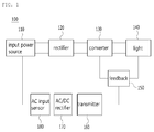
- the conventional lighting control apparatus in order to sense the state (150V to 250V) of input voltage in real time and receive a value, the conventional lighting control apparatus essentially includes various components at the primary winding, for instance, an AC input sensor 180, an AC/DC rectifier 170 and a transmitter 160.
- the present invention has been made in view of the above-mentioned problems occurring in the prior art, and it is an object of the present invention to provide an apparatus for sensing input power source capable of simplifying structure and miniaturizing parts by removing unnecessary components of the primary side due to a dimming interface mounted at the secondary side.
- an apparatus for sensing input power source including: an input power source providing an input voltage (Vin); a rectifier for rectifying input voltage (Vin) of the input power source into rectified voltage (Vr); a dimming interface for sensing the state of the input power source; a first light; and a converter for converting the rectified voltage (Vr) into a first voltage source (V21) and a second voltage source (V22) which were preset to apply them to the dimming interface and the first light, wherein the dimming interface and the first light are connected with the converter in a feedback type.
- the converter includes: a transformer having a winding of the primary side and a plurality of windings of the secondary side; a switch for turning on and off the converter; and a PWM controller for controlling the switch.
- the transformer includes: a first winding which is located at the primary side to receive the rectified voltage (Vr); a second winding which is located at the secondary side to receive the first voltage source (V21) according to the turns ratio with the first winding and is connected to the dimming interface; and a third winding which is located at the secondary side to receive the second voltage source (V22) according to the turns ratio with the first winding and is connected to the first light.
- the turns ratio of the first winding to the second winding is 1:N1 and the turns ratio of the first winding to the third winding is 1:N2.
- the first winding and the switch are connected to each other in series.
- the second winding is a forward converter which is in the same direction as the first winding
- the third winding is a flyback converter which is in the reverse direction to the first winding.
- the apparatus for sensing input power source further includes a second light, a third light,..., and a nth light
- the transformer includes a plurality of windings which are located at the secondary side to receive voltage source according to the turns ratio with the first winding and are respectively connected to a plurality of the lights.
- the windings are flyback converters which are in the opposite direction to the first winding, and the second light, the third light... and the nth light are reconnected with the converter in the feedback type.
- the switch is an FET
- the PWM controller is connected with a gate of the FET.
- the input power source is commercial AC power source (220V)
- the rectifier is a bridge rectifier.
- the dimming interface includes: a dimming output terminal for sensing the output power source when the output power source is applied in proportion to the preset input power source; a peak rectifier for rectifying the output power source into DC; and a dimming signal generator which is connected with the peak rectifier in series to generate references.
- Vin is input voltage
- Vout is output voltage
- N1 is a turns ratio of the second winding
- D is a cycle of input power source.
- the apparatus for sensing input power source further includes: a compensator which compensates according to references generated by the dimming interface and transfers a compensated value to the feedback controller; and a feedback controller which transfers the value compensated by the compensator to the converter.
- the compensator is connected with the dimming interface and the first light, and the compensator and the feedback controller are connected to the PWM controller of the converter in series.
- the conventional lighting control apparatus has a disadvantage in that a configuration of circuits to satisfy the safety requirements is required and must be applied to components because components, such as the AC input sensor, the AC/DC rectifier, the transmitter and the u-processing unit, are mounted at the primary side in order to sense input power source.
- the apparatus for sensing input power source can directly sense input power source of the primary side at the secondary side because a winding is additionally disposed at the secondary side of the transformer 231 of the converter to connect the dimming interface.
- a winding 233 for the forward converter is additionally mounted on the transformer 231 and output voltage is converted into peak output voltage through a peak rectifier so as to sense the state of input power source for implementing the existing AC dimming. Therefore, the present invention does not need the component to transfer the value of the sensed input power source to the dimming interface.
- the conventional apparatus has a disadvantage in that all of the first circuit and the second circuit must be inspected for maintenance.
- the apparatus for sensing input power source according to the preferred embodiment of the present invention has an advantage in that only the dimming interface 240 included in the second circuit is inspected.
- the apparatus for sensing input power source does not require additional configuration of circuits and applied components for satisfying the safety requirements which are different in many countries, thereby simplifying the structure and miniaturizing the components.
- 'power source' includes all kinds of electric energies to be used to general electric circuits, such as 'voltage', 'electric power' and 'current'.
- FIG. 1 illustrates a configuration of a conventional lighting control apparatus.
- the conventional lighting control apparatus requisitely includes various components, such as the AC input sensor 180, the AC/DC rectifier 170 and the transmitter 160, in order to configure circuits to sense input power source and apply the circuits to the components. Additionally, the conventional lighting control apparatus still has inconvenience to control the circuits not to be against the safety requirements which are different in many countries.
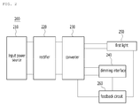
- FIG. 2 is a view of a configuration of an apparatus for sensing input power source according to a preferred embodiment of the present invention
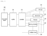
- FIG. 3 is an exemplary view showing a configuration that a plurality of lights are mounted on the input power sensing apparatus according to the present invention.
- the input power source sensing apparatus 200 includes an input power unit 210 providing an input voltage (Vin), a rectifier 220, a converter 230, a dimming interface 240, a first light 250 and a feedback circuit 260.
- the input power unit 210 provides input voltage necessary for the input power source sensing apparatus or a dimming control apparatus, and in this instance, it is preferable that input power source 210 be commercial AC power 220V.
- the rectifier 220 rectifies the input voltage (Vin) of the input power source into rectified voltage (Vr).
- the lighting unit is operated by DC power source, but because the power source is AC power source, it is necessary to convert the commercial AC power source into DC power source.
- the present invention includes the rectifier 220.
- the rectifier 220 may be implemented through rectifier elements of various types, such as a bridge rectifier, a half bridge rectifier, a full bridge rectifier and so on.
- the converter 230 converts the rectified voltage (Vr) into a first voltage source (V21) and a second voltage source (V22) which were preset and applies the converted voltage sources to the dimming interface and the first light.
- the first voltage source and the second voltage source which were preset can be controlled according to a turns ratio of the primary side/the secondary side of the transformer 231 included in the converter 230.
- the converter includes the transformer 231, a switch 235 and a PWM controller 236, and referring to FIG. 4 , operations of the components will be described in detail.
- the dimming interface 240 is connected to the converter to sense the state of the input power source. Furthermore, the dimming interface includes a dimming output terminal 241, a peak rectifier 242 and a dimming signal generator 243, and referring to FIG. 4 , operations of the components will be described in detail.
- the first light 250 is connected to the converter, serves as a light source by converting the applied second voltage source into light energy.
- All light sources capable of being used as a lighting unit such as incandescent lamps, fluorescent lamps, LEDs and OLEDs, can be applied.
- the dimming interface and the first light are reconnected to the converter in a feedback type so as to transfer information of the present output voltage to the PWM controller included in the converter.
- a second light, a third light,..., a nth light may be further included in such a way that a single input power sensing apparatus can control the plural lights.
- the lights can receive electric voltage through windings added to the secondary side of the transformer. Because the received electric voltage is varied according to the turns ratio between the primary side and the secondary side, when the turns ratio is controlled, different voltage sources can be applied to the plural lights.
- the second light, the third light... and the nth light are reconnected with the converter in the feedback type so as to transfer information of the present output voltage source to the PWM controller included in the converter.
- the order that the lights and the dimming interface are located on the transformer can be freely arranged according to a user's setting.
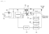
- FIG. 4 is a circuit diagram showing a detailed configuration of the input power sensing apparatus according to the present invention.
- the converter 230 includes the transformer 231, the switch 235 and the PWM controller 236.
- the transformer 231 includes a primary winding and a plurality of secondary windings, and can apply voltage source applied to the primary winding by an induced electromotive force to the secondary winding according to the turns ratio.
- the transformer includes: a first winding 232 which is located at the primary side to receive the rectified voltage (Vr); a second winding (233) which is located at the secondary side to receive the first voltage source (V21) according to the turns ratio with the first winding and is connected to the dimming interface; and a third winding 234 which is located at the secondary side to receive the second voltage source (V22) according to the turns ratio with the first winding and is connected to the first light. Therefore, the second voltage source (V22) is applied to the first light, and the first voltage source (V21) is applied to the dimming interface.
- the turns ratio of the first winding 232 to the second winding 233 is 1:N1 and the turns ratio of the first winding 232 to the third winding 234 is 1:N2
- intensity of voltage is determined by the following relational formula.
- the turns ratios, 1:N1 and 1:N2 may be implemented at the same turns ratio or at different turns ratios according to the user's setting.
- V r V 21 N 1
- V r V 22 N 2
- the second winding is a forward converter in the same direction as the first winding
- the third winding is a flyback converter in the reverse direction to the first winding.
- the dimming interface uses winding for the forward converter to transfer voltage as it is because serving to sense input power source
- the lighting unit uses winding for the flyback converter which is varied according to output voltage.
- windings respectively connected with the lights are flyback converters.
- the switch 235 turns on and off the entire of the converter 230.
- the switch may be connected with the first winding in series. Additionally, it is preferable that the switch be a field effect transistor (FET), and the PWM controller may be connected with a gate of the FET.
- FET field effect transistor
- the PWM controller 236 controls the switch.
- the voltage source applied to the first winding 232 becomes DC power source after passing through the rectifier 220, and in this instance, when the switch is turned on and off on a cycle (D; duty) by the PWM controller, the DC power source is converted into a square wave form.
- the dimming interface 240 senses the state of the input power source.
- the dimming interface includes the dimming output terminal 241, the peak rectifier 242 and the dimming signal generator 243.
- the dimming output terminal 241 can sense output power source when the output power source is applied in proportion to the preset input power source.
- Vin is input voltage
- Vout is output voltage
- N1 is a turns ratio of the second winding
- D is a cycle of input power source.
- the output power source sensed by the output terminal of the input power source sensing apparatus is proportional to the input power source, when the output power source is measured, the input power source can be sensed.
- the peak rectifier 242 rectifies the output power source into DC and transfers the rectified DC power source to the dimming signal generator 243. Moreover, the dimming signal generator 243 is connected with the peak rectifier in series to generate references to be used in a compensator 261.
- the input power source sensing apparatus 200 further includes a compensator 261 and a feedback controller 262.
- the compensator 261 compensates according to references generated by the dimming interface and transfers a compensated value to the feedback controller, and the feedback controller 262 transfers the value compensated by the compensator to the converter.
- the compensator is connected with the dimming interface and the first light, and the compensator and the feedback controller are connected to the PWM controller in series.
Landscapes
- Engineering & Computer Science (AREA)
- Power Engineering (AREA)
- Circuit Arrangement For Electric Light Sources In General (AREA)
- General Engineering & Computer Science (AREA)
- Dc-Dc Converters (AREA)
- Microelectronics & Electronic Packaging (AREA)
Abstract
Description
- The present invention relates to an apparatus for sensing input power source which includes an input power source, providing an input voltage (Vin); a rectifier for rectifying input voltage (Vin) of the input power source into rectified voltage (Vr); a dimming interface for sensing the state of the input power source; a first light; and a converter for converting the rectified voltage (Vr) into a first voltage source (V21) and a second voltage source (V22) which were preset to apply them to the dimming interface and the first light, wherein the dimming interface and the first light are connected with the converter in a feedback type.
- In general, light emitting diodes (LEDs) are a sort of semiconductor devices which convert electric energy into light. The LEDs are lower in power consumption than conventional light sources, such as fluorescent lamps or incandescent lamps and have various advantages of semi-permanent lifespan, rapid speed of response, safety and environment friendliness. Particularly, LED lighting devices can show various effects through control of flickering order, luminous colors and brightness of a plurality of arrayed LEDs.
- Therefore, lots of studies to substitute the conventional light sources with LEDs have been made, and the use of LEDs as light sources for lighting devices, such as various lamps, liquid crystal display devices, electric sign boards, street lamps and so on, which are used outdoors is on a rising trend. Especially, LEDs are also used as lighting for room interior, stage lighting for showing a special atmosphere, lighting for advertisement, landscape lighting and so on.
- Lighting devices as landscape lighting may be installed on the outer wall of a building, in a park, on a street lamp, on a bridge rail or in a performing place, and sizes and application systems of the lighting devices may be changed according to applied purposes, targets or locations. That is, the lighting devices installed on the outer wall of a building are used just to provide a flickering function in a band type or used for simple expression of a single color or a combined color, and the lighting devices installed in a park or on a street lamp or a bridge rail are irregularly installed according to the form of the object to which the lighting devices are installed while changing flickers or colors.
- In this instance, referring to
FIG. 1 , because a conventional lighting control apparatus is varied in LED dimming degree according to input power sources, in order to sense the state (150V to 250V) of input voltage in real time and receive a value, the conventional lighting control apparatus essentially includes various components at the primary winding, for instance, anAC input sensor 180, an AC/DC rectifier 170 and atransmitter 160. - However, because countries in the world have different safety requirements for lighting devices and it is difficult to realize standards of lighting control apparatuses to satisfy all countries, various studies to apply a configuration of circuits and components which are not against the safety requirements of an isolated converter have been made.
- Accordingly, the present invention has been made in view of the above-mentioned problems occurring in the prior art, and it is an object of the present invention to provide an apparatus for sensing input power source capable of simplifying structure and miniaturizing parts by removing unnecessary components of the primary side due to a dimming interface mounted at the secondary side.
- The present invention is not limited to the above-mentioned object, and additional various objects will be apparent from the following detailed description of the present invention within the technical scope, which is obvious to those skilled in the art.
- To accomplish the above object, according to the present invention, there is provided an apparatus for sensing input power source including: an input power source providing an input voltage (Vin); a rectifier for rectifying input voltage (Vin) of the input power source into rectified voltage (Vr); a dimming interface for sensing the state of the input power source; a first light; and a converter for converting the rectified voltage (Vr) into a first voltage source (V21) and a second voltage source (V22) which were preset to apply them to the dimming interface and the first light, wherein the dimming interface and the first light are connected with the converter in a feedback type.
- Moreover, in the preferred embodiment of the present invention, the converter includes: a transformer having a winding of the primary side and a plurality of windings of the secondary side; a switch for turning on and off the converter; and a PWM controller for controlling the switch.
- In this instance, in the preferred embodiment of the present invention, the transformer includes: a first winding which is located at the primary side to receive the rectified voltage (Vr); a second winding which is located at the secondary side to receive the first voltage source (V21) according to the turns ratio with the first winding and is connected to the dimming interface; and a third winding which is located at the secondary side to receive the second voltage source (V22) according to the turns ratio with the first winding and is connected to the first light.
- Furthermore, in the preferred embodiment of the present invention, the turns ratio of the first winding to the second winding is 1:N1 and the turns ratio of the first winding to the third winding is 1:N2. The first winding and the switch are connected to each other in series.
- Additionally, the second winding is a forward converter which is in the same direction as the first winding, and the third winding is a flyback converter which is in the reverse direction to the first winding.
- In addition, the apparatus for sensing input power source further includes a second light, a third light,..., and a nth light, wherein the transformer includes a plurality of windings which are located at the secondary side to receive voltage source according to the turns ratio with the first winding and are respectively connected to a plurality of the lights.
- In this instance, in the preferred embodiment of the present invention, the windings are flyback converters which are in the opposite direction to the first winding, and the second light, the third light... and the nth light are reconnected with the converter in the feedback type.
- Moreover, in the preferred embodiment of the present invention, the switch is an FET, and the PWM controller is connected with a gate of the FET.
- Furthermore, in the preferred embodiment of the present invention, the input power source is commercial AC power source (220V), and the rectifier is a bridge rectifier.
- Meanwhile, in the preferred embodiment of the present invention, the dimming interface includes: a dimming output terminal for sensing the output power source when the output power source is applied in proportion to the preset input power source; a peak rectifier for rectifying the output power source into DC; and a dimming signal generator which is connected with the peak rectifier in series to generate references.
- In this instance, in the preferred embodiment of the present invention, the output voltage of the output terminal is determined by the following formula:

- wherein Vin is input voltage, Vout is output voltage, N1 is a turns ratio of the second winding, and D is a cycle of input power source.
- Additionally, in the preferred embodiment of the present invention, the apparatus for sensing input power source further includes: a compensator which compensates according to references generated by the dimming interface and transfers a compensated value to the feedback controller; and a feedback controller which transfers the value compensated by the compensator to the converter.
- In this instance, in the preferred embodiment of the present invention, the compensator is connected with the dimming interface and the first light, and the compensator and the feedback controller are connected to the PWM controller of the converter in series.
- The conventional lighting control apparatus has a disadvantage in that a configuration of circuits to satisfy the safety requirements is required and must be applied to components because components, such as the AC input sensor, the AC/DC rectifier, the transmitter and the u-processing unit, are mounted at the primary side in order to sense input power source.
- However, the apparatus for sensing input power source according to the preferred embodiment of the present invention can directly sense input power source of the primary side at the secondary side because a winding is additionally disposed at the secondary side of the
transformer 231 of the converter to connect the dimming interface. - For this, a
winding 233 for the forward converter is additionally mounted on thetransformer 231 and output voltage is converted into peak output voltage through a peak rectifier so as to sense the state of input power source for implementing the existing AC dimming. Therefore, the present invention does not need the component to transfer the value of the sensed input power source to the dimming interface. - Moreover, the conventional apparatus has a disadvantage in that all of the first circuit and the second circuit must be inspected for maintenance. However, the apparatus for sensing input power source according to the preferred embodiment of the present invention has an advantage in that only the
dimming interface 240 included in the second circuit is inspected. - Furthermore, if a converter is mounted, the apparatus for sensing input power source according to the preferred embodiment of the present invention does not require additional configuration of circuits and applied components for satisfying the safety requirements which are different in many countries, thereby simplifying the structure and miniaturizing the components.
- The above and other objects, features and advantages of the present invention will be apparent from the following detailed description of the preferred embodiments of the invention in conjunction with the accompanying drawings, in which:
-
FIG. 1 is a view of a configuration of a conventional lighting control apparatus; -
FIG. 2 is a view of a configuration of an apparatus for sensing input power source according to a preferred embodiment of the present invention; -
FIG. 3 is an exemplary view showing a configuration that a plurality of lights are mounted on the input power sensing apparatus according to the present invention; -
FIG. 4 is a circuit diagram showing a detailed configuration of the input power sensing apparatus according to the present invention; -
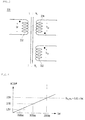
FIG. 5 is a circuit diagram showing a turns ratio and applied power source of windings of a transformer located at the primary side and the secondary side; and -
FIG. 6 is a graph showing that output voltage sensed by an output terminal of the input power source sensing apparatus according to the preferred embodiment of the present invention is proportional to the input voltage. - Hereinafter, with reference to the attached drawings, an apparatus for sensing input power source according to preferred embodiments of the present invention will be described in detail. The example embodiments which will be described later are provided to make those skilled in the art easily understand the present invention, and hence, it should be understood that there is no intent to limit the present invention to the particular forms of the embodiments. Matters illustrated in the attached drawings are schematized in the drawings in order to easily explain the embodiments of the present invention, and hence, may be different from the actual forms.
- In the meantime, it should be further understood that components described hereinafter are just examples for realizing the present invention. Therefore, the present invention may have different components without departing from the technical idea and scope of the present invention. Furthermore, the components of the present invention may be realized just by hardware or software, but may be realized in combination of various hardware and software parts which carry out the same functions.
- Moreover, it should be also understood that the terms of 'include' or 'have' in the specification are 'open type' expressions just to say that components exit and do not exclude additional components.
- Additionally, it should be also understood that the terms, such as 'first' and 'second', are just used to tell plural components and do not restrict order or characteristics among the components.
- In addition, in the present invention, 'power source' includes all kinds of electric energies to be used to general electric circuits, such as 'voltage', 'electric power' and 'current'.
-
FIG. 1 illustrates a configuration of a conventional lighting control apparatus. - Referring to
FIG. 1 , the conventional lighting control apparatus requisitely includes various components, such as theAC input sensor 180, the AC/DC rectifier 170 and thetransmitter 160, in order to configure circuits to sense input power source and apply the circuits to the components. Additionally, the conventional lighting control apparatus still has inconvenience to control the circuits not to be against the safety requirements which are different in many countries. -
FIG. 2 is a view of a configuration of an apparatus for sensing input power source according to a preferred embodiment of the present invention, andFIG. 3 is an exemplary view showing a configuration that a plurality of lights are mounted on the input power sensing apparatus according to the present invention. - Referring to
FIG. 2 , the input powersource sensing apparatus 200 according to the preferred embodiment of the present invention includes aninput power unit 210 providing an input voltage (Vin), arectifier 220, aconverter 230, adimming interface 240, afirst light 250 and afeedback circuit 260. - The
input power unit 210 provides input voltage necessary for the input power source sensing apparatus or a dimming control apparatus, and in this instance, it is preferable thatinput power source 210 be commercial AC power 220V. Therectifier 220 rectifies the input voltage (Vin) of the input power source into rectified voltage (Vr). The lighting unit is operated by DC power source, but because the power source is AC power source, it is necessary to convert the commercial AC power source into DC power source. For this, the present invention includes therectifier 220. - The
rectifier 220 may be implemented through rectifier elements of various types, such as a bridge rectifier, a half bridge rectifier, a full bridge rectifier and so on. - The
converter 230 converts the rectified voltage (Vr) into a first voltage source (V21) and a second voltage source (V22) which were preset and applies the converted voltage sources to the dimming interface and the first light. In this instance, the first voltage source and the second voltage source which were preset can be controlled according to a turns ratio of the primary side/the secondary side of thetransformer 231 included in theconverter 230. Moreover, the converter includes thetransformer 231, aswitch 235 and aPWM controller 236, and referring toFIG. 4 , operations of the components will be described in detail. - The dimming
interface 240 is connected to the converter to sense the state of the input power source. Furthermore, the dimming interface includes a dimmingoutput terminal 241, apeak rectifier 242 and adimming signal generator 243, and referring toFIG. 4 , operations of the components will be described in detail. - The
first light 250 is connected to the converter, serves as a light source by converting the applied second voltage source into light energy. All light sources capable of being used as a lighting unit, such as incandescent lamps, fluorescent lamps, LEDs and OLEDs, can be applied. In this instance, the dimming interface and the first light are reconnected to the converter in a feedback type so as to transfer information of the present output voltage to the PWM controller included in the converter. - Moreover, referring to
FIG. 3 , a second light, a third light,..., a nth light may be further included in such a way that a single input power sensing apparatus can control the plural lights. In this instance, the lights can receive electric voltage through windings added to the secondary side of the transformer. Because the received electric voltage is varied according to the turns ratio between the primary side and the secondary side, when the turns ratio is controlled, different voltage sources can be applied to the plural lights. In addition, the second light, the third light... and the nth light are reconnected with the converter in the feedback type so as to transfer information of the present output voltage source to the PWM controller included in the converter. - In this instance, the order that the lights and the dimming interface are located on the transformer can be freely arranged according to a user's setting.
-
FIG. 4 is a circuit diagram showing a detailed configuration of the input power sensing apparatus according to the present invention. - Referring to
FIG. 4 , theconverter 230 includes thetransformer 231, theswitch 235 and thePWM controller 236. - The
transformer 231 includes a primary winding and a plurality of secondary windings, and can apply voltage source applied to the primary winding by an induced electromotive force to the secondary winding according to the turns ratio. In this instance, the transformer includes: a first winding 232 which is located at the primary side to receive the rectified voltage (Vr); a second winding (233) which is located at the secondary side to receive the first voltage source (V21) according to the turns ratio with the first winding and is connected to the dimming interface; and a third winding 234 which is located at the secondary side to receive the second voltage source (V22) according to the turns ratio with the first winding and is connected to the first light. Therefore, the second voltage source (V22) is applied to the first light, and the first voltage source (V21) is applied to the dimming interface. - Referring to
FIG. 5 , when the turns ratio of the first winding 232 to the second winding 233 is 1:N1 and the turns ratio of the first winding 232 to the third winding 234 is 1:N2, intensity of voltage is determined by the following relational formula. In this instance, the turns ratios, 1:N1 and 1:N2, may be implemented at the same turns ratio or at different turns ratios according to the user's setting.
- Furthermore, the second winding is a forward converter in the same direction as the first winding, and the third winding is a flyback converter in the reverse direction to the first winding. The dimming interface uses winding for the forward converter to transfer voltage as it is because serving to sense input power source, and the lighting unit uses winding for the flyback converter which is varied according to output voltage. Moreover, if a plurality of the lights are added, windings respectively connected with the lights are flyback converters. The
switch 235 turns on and off the entire of theconverter 230. The switch may be connected with the first winding in series. Additionally, it is preferable that the switch be a field effect transistor (FET), and the PWM controller may be connected with a gate of the FET. - The
PWM controller 236 controls the switch. The voltage source applied to the first winding 232 becomes DC power source after passing through therectifier 220, and in this instance, when the switch is turned on and off on a cycle (D; duty) by the PWM controller, the DC power source is converted into a square wave form. - The dimming
interface 240 senses the state of the input power source. In this instance, the dimming interface includes the dimmingoutput terminal 241, thepeak rectifier 242 and thedimming signal generator 243. - The dimming
output terminal 241 can sense output power source when the output power source is applied in proportion to the preset input power source. The output power source sensed by the dimmingoutput terminal 241 is proportional to the input power source according to the turns ratio of the transformer. Therefore, when the output voltage is measured, the input voltage can be calculated by the following formula:
- wherein Vin is input voltage, Vout is output voltage, N1 is a turns ratio of the second winding, and D is a cycle of input power source.
- Therefore, referring to
FIG. 6 , because the output power source sensed by the output terminal of the input power source sensing apparatus is proportional to the input power source, when the output power source is measured, the input power source can be sensed. - The
peak rectifier 242 rectifies the output power source into DC and transfers the rectified DC power source to thedimming signal generator 243. Moreover, thedimming signal generator 243 is connected with the peak rectifier in series to generate references to be used in acompensator 261. - Furthermore, the input power
source sensing apparatus 200 according to the preferred embodiment of the present invention further includes acompensator 261 and afeedback controller 262. - The
compensator 261 compensates according to references generated by the dimming interface and transfers a compensated value to the feedback controller, and thefeedback controller 262 transfers the value compensated by the compensator to the converter. - In this instance, the compensator is connected with the dimming interface and the first light, and the compensator and the feedback controller are connected to the PWM controller in series.
- While the present invention has been particularly shown and described with reference to exemplary embodiments thereof, it will be understood by those of ordinary skill in the art that there is no intent to limit example embodiments of the invention to the particular forms disclosed and that various changes and modifications may be made therein without departing from the technical idea and scope of the present invention and such changes and modifications belong to the claims of the present invention.
Claims (16)
- An apparatus for sensing input power source (200) comprising:an input power source (210) providing an input voltage (Vin);a rectifier (220) for rectifying input voltage (Vin) of the input power source (210) into rectified voltage (Vr);a dimming interface (240) for sensing the state of the input power source (210);a first light (250); anda converter (230) for converting the rectified voltage (Vr) into a first voltage source (V21) and a second voltage source (V22) which were preset to apply them to the dimming interface (240) and the first light (250),wherein the dimming interface (240) and the first light (250) are connected with the converter (230) in a feedback type.
- The apparatus (200) according to claim 1, wherein the converter (230) comprises:a transformer (231) having a winding of the primary side and a plurality of windings of the secondary side;a switch (235) for turning on and off the converter (230); anda PWM controller (236) for controlling the switch (235).
- The apparatus (200) according to claim 2, wherein the transformer (231) comprises:a first winding (232) which is located at the primary side to receive the rectified voltage (Vr);a second winding (233) which is located at the secondary side to receive the first voltage source (V21) according to the turns ratio with the first winding (232) and is connected to the dimming interface (240); anda third winding (234) which is located at the secondary side to receive the second voltage source (V22) according to the turns ratio with the first winding (232) and is connected to the first light (250).
- The apparatus (200) according to claim 3, wherein the turns ratio of the first winding (232) to the second winding (233) is 1:N1 and the turns ratio of the first winding (232) to the third winding (234) is 1:N2.
- The apparatus (200) according to claim 3, wherein the first winding (232) and the switch (235) are connected to each other in series.
- The apparatus (200) according to claim 3, wherein the second winding (233) is a forward converter which is in the same direction as the first winding (232), and the third winding (234) is a flyback converter which is in the reverse direction to the first winding (232).
- The apparatus (200) according to claim 3, further comprising:a second light (251), a third light,..., and a nth light (252),wherein the transformer (231) includes a plurality of windings which are located at the secondary side to receive voltage source according to the turns ratio with the first winding (232) and are respectively connected to a plurality of the lights.
- The apparatus (200) according to claim 7, wherein the windings are flyback converters which are in the opposite direction to the first winding (232).
- The apparatus (200) according to claim 7, wherein the second light (251), the third light... and the nth light (252) are reconnected with the converter (230) in the feedback type.
- The apparatus (200) according to claim 2, wherein the switch (235) is an FET, and the PWM controller (236) is connected with a gate of the FET.
- The apparatus (200) according to claim 1, wherein the input power source (210) is commercial AC power source (220V).
- The apparatus (200) according to claim 1, wherein the rectifier (220) is a bridge rectifier.
- The apparatus (200) according to claim 1, wherein the dimming interface (240) comprises:a dimming output terminal (241) for sensing the output power source when the output power source is applied in proportion to the preset input power source;a peak rectifier (242) for rectifying the output power source into DC; anda dimming signal generator (243) which is connected with the peak rectifier (242) in series to generate references.
- The apparatus (200) according to claim 13, wherein the output voltage of the output terminal is determined by the following formula:

- The apparatus (200) according to claim 1, further comprising:a compensator (261) which compensates according to references generated by the dimming interface (240) and transfers a compensated value to the feedback controller (260); anda feedback controller (260) which transfers the value compensated by the compensator (261) to the converter (230).
- The apparatus (200) according to claim 15, wherein the compensator (261) is connected with the dimming interface (240) and the first light (250), and
wherein the compensator (261) and the feedback controller (260) are connected to the PWM controller (236) of the converter (230) in series.
Applications Claiming Priority (1)
| Application Number | Priority Date | Filing Date | Title |
|---|---|---|---|
| KR1020150097251A KR20170006522A (en) | 2015-07-08 | 2015-07-08 | Apparatus for sensing input voltage |
Publications (1)
| Publication Number | Publication Date |
|---|---|
| EP3116114A1 true EP3116114A1 (en) | 2017-01-11 |
Family
ID=57046940
Family Applications (1)
| Application Number | Title | Priority Date | Filing Date |
|---|---|---|---|
| EP16178502.7A Ceased EP3116114A1 (en) | 2015-07-08 | 2016-07-07 | Apparatus for sensing input power source |
Country Status (5)
| Country | Link |
|---|---|
| US (1) | US9615416B2 (en) |
| EP (1) | EP3116114A1 (en) |
| JP (1) | JP2017022981A (en) |
| KR (1) | KR20170006522A (en) |
| CN (1) | CN106341935A (en) |
Citations (2)
| Publication number | Priority date | Publication date | Assignee | Title |
|---|---|---|---|---|
| US20110031899A1 (en) * | 2009-08-07 | 2011-02-10 | Chung-Jen Chu | Dimmable led device with low ripple current and driving circuit thereof |
| WO2014195385A1 (en) * | 2013-06-05 | 2014-12-11 | Koninklijke Philips N.V. | Apparatus for controlling light module |
Family Cites Families (11)
| Publication number | Priority date | Publication date | Assignee | Title |
|---|---|---|---|---|
| US6486616B1 (en) * | 2000-02-25 | 2002-11-26 | Osram Sylvania Inc. | Dual control dimming ballast |
| CN201256471Y (en) * | 2008-09-11 | 2009-06-10 | 源辰光科股份有限公司 | Light emitting diode driving circuit |
| US8102683B2 (en) * | 2010-02-09 | 2012-01-24 | Power Integrations, Inc. | Phase angle measurement of a dimming circuit for a switching power supply |
| CN102238768B (en) * | 2010-04-26 | 2014-04-09 | 光宝电子(广州)有限公司 | Light emitting diode backlight source driving module |
| TWI440398B (en) * | 2010-09-13 | 2014-06-01 | Richtek Technology Corp | Direct current light emitting device control circuit with dimming function and method thereof |
| CN102469647B (en) * | 2010-11-04 | 2014-10-08 | 登丰微电子股份有限公司 | Feedback control circuit and LED drive circuit |
| TWI429175B (en) * | 2011-03-04 | 2014-03-01 | Wen Chung Yeh | Power manager, control method and integrated circuit |
| KR101455146B1 (en) | 2013-01-02 | 2014-11-03 | 주식회사 케이비텍 | LED dimming converter |
| KR20150051028A (en) | 2013-11-01 | 2015-05-11 | 주식회사 유신라이텍 | LED lamp capable of smoothly controlling the brightness thereof over the full range of the dimmer control |
| US9386648B2 (en) * | 2014-12-05 | 2016-07-05 | Abl Ip Holding, Llc | Systems, apparatus, and methods for converting a bi-level lighting system to a dimmable lighting system |
| US9787191B2 (en) * | 2015-07-08 | 2017-10-10 | Infineon Technologies Austria Ag | Converter with quasi-resonant mode of operation for supplying power to a load |
-
2015
- 2015-07-08 KR KR1020150097251A patent/KR20170006522A/en not_active Withdrawn
-
2016
- 2016-07-07 JP JP2016135036A patent/JP2017022981A/en not_active Withdrawn
- 2016-07-07 US US15/204,013 patent/US9615416B2/en not_active Expired - Fee Related
- 2016-07-07 EP EP16178502.7A patent/EP3116114A1/en not_active Ceased
- 2016-07-08 CN CN201610537624.6A patent/CN106341935A/en active Pending
Patent Citations (2)
| Publication number | Priority date | Publication date | Assignee | Title |
|---|---|---|---|---|
| US20110031899A1 (en) * | 2009-08-07 | 2011-02-10 | Chung-Jen Chu | Dimmable led device with low ripple current and driving circuit thereof |
| WO2014195385A1 (en) * | 2013-06-05 | 2014-12-11 | Koninklijke Philips N.V. | Apparatus for controlling light module |
Non-Patent Citations (2)
| Title |
|---|
| CARL NELSON: "Application Note 19 - LT1070 Design Manual", 1 June 1986 (1986-06-01), XP055218203, Retrieved from the Internet <URL:http://cds.linear.com/docs/en/application-note/an19fc.pdf> [retrieved on 20151005] * |
| MULLETT C ET AL: "Improving the Regulation of Multi-Output Flyback Converters", APPLIED POWER ELECTRONICS CONFERENCE AND EXPOSITION, 2009. APEC 2009. TWENTY-FOURTH ANNUAL IEEE, IEEE, PISCATAWAY, NJ, USA, 15 February 2009 (2009-02-15), pages 1923 - 1926, XP031442956, ISBN: 978-1-4244-2811-3 * |
Also Published As
| Publication number | Publication date |
|---|---|
| JP2017022981A (en) | 2017-01-26 |
| CN106341935A (en) | 2017-01-18 |
| US9615416B2 (en) | 2017-04-04 |
| US20170013687A1 (en) | 2017-01-12 |
| KR20170006522A (en) | 2017-01-18 |
Similar Documents
| Publication | Publication Date | Title |
|---|---|---|
| KR101016074B1 (en) | LED bulb having dimming function which can be adjusted by AC signal, light emitting device control method and light emitting device controller circuit | |
| JP6403042B2 (en) | Power supply apparatus and lighting apparatus using the same | |
| KR20080001050A (en) | LC backlight drive system with LED | |
| TW201234919A (en) | Single power stage for LED driver and other power supplies | |
| WO2012008800A2 (en) | Power integrated circuit for led lighting | |
| KR102396417B1 (en) | Apparatus for controlling Lamp light | |
| JP2010257718A (en) | LED lighting device and marker lamp system | |
| EP2936930B1 (en) | Led driver circuit using flyback converter to reduce observable optical flicker by reducing rectified ac mains ripple | |
| JP2006139755A5 (en) | ||
| US8674615B2 (en) | Control apparatus for LED diodes | |
| JP2009301876A (en) | Led lighting system | |
| JP2008166192A (en) | LED drive power circuit | |
| KR100966339B1 (en) | Lighting drive | |
| CN108156691B (en) | Non-point light source non-stroboscopic light modulation circuit | |
| US9101000B2 (en) | Dimmable LED illuminating system | |
| US8111015B2 (en) | Brightness-adjustable illumination driving system | |
| US9615416B2 (en) | Apparatus for sensing input power source | |
| Cardesín et al. | Low cost intelligent LED driver for public Lighting Smart Grids | |
| KR20190010261A (en) | Led lighting device, and light control method of the same | |
| CN103152934A (en) | LED (Light Emitting Diode) drive circuit capable of adjusting light and color temperature | |
| EP3764743A1 (en) | Lighting control apparatus | |
| KR101961850B1 (en) | Apparatus for controlling the led lighting | |
| KR102517841B1 (en) | Apparatus for controlling LEDs using integrated cable and radio dimming circuit | |
| KR101839052B1 (en) | Power converter | |
| US9380670B2 (en) | Generating a voltage feedback signal in non-isolated LED drivers |
Legal Events
| Date | Code | Title | Description |
|---|---|---|---|
| PUAI | Public reference made under article 153(3) epc to a published international application that has entered the european phase |
Free format text: ORIGINAL CODE: 0009012 |
|
| STAA | Information on the status of an ep patent application or granted ep patent |
Free format text: STATUS: THE APPLICATION HAS BEEN PUBLISHED |
|
| AK | Designated contracting states |
Kind code of ref document: A1 Designated state(s): AL AT BE BG CH CY CZ DE DK EE ES FI FR GB GR HR HU IE IS IT LI LT LU LV MC MK MT NL NO PL PT RO RS SE SI SK SM TR |
|
| AX | Request for extension of the european patent |
Extension state: BA ME |
|
| RAP3 | Party data changed (applicant data changed or rights of an application transferred) |
Owner name: LG INNOTEK CO., LTD. |
|
| RAP1 | Party data changed (applicant data changed or rights of an application transferred) |
Owner name: LG INNOTEK CO., LTD. |
|
| STAA | Information on the status of an ep patent application or granted ep patent |
Free format text: STATUS: REQUEST FOR EXAMINATION WAS MADE |
|
| 17P | Request for examination filed |
Effective date: 20170613 |
|
| RBV | Designated contracting states (corrected) |
Designated state(s): AL AT BE BG CH CY CZ DE DK EE ES FI FR GB GR HR HU IE IS IT LI LT LU LV MC MK MT NL NO PL PT RO RS SE SI SK SM TR |
|
| STAA | Information on the status of an ep patent application or granted ep patent |
Free format text: STATUS: EXAMINATION IS IN PROGRESS |
|
| 17Q | First examination report despatched |
Effective date: 20180410 |
|
| STAA | Information on the status of an ep patent application or granted ep patent |
Free format text: STATUS: THE APPLICATION HAS BEEN REFUSED |
|
| 18R | Application refused |
Effective date: 20200315 |