EP3115978A1 - Monitoring - Google Patents
Monitoring Download PDFInfo
- Publication number
- EP3115978A1 EP3115978A1 EP15175986.7A EP15175986A EP3115978A1 EP 3115978 A1 EP3115978 A1 EP 3115978A1 EP 15175986 A EP15175986 A EP 15175986A EP 3115978 A1 EP3115978 A1 EP 3115978A1
- Authority
- EP
- European Patent Office
- Prior art keywords
- computer
- space
- virtual boundary
- monitored scene
- implemented virtual
- Prior art date
- Legal status (The legal status is an assumption and is not a legal conclusion. Google has not performed a legal analysis and makes no representation as to the accuracy of the status listed.)
- Granted
Links
Images




Classifications
-
- G—PHYSICS
- G05—CONTROLLING; REGULATING
- G05D—SYSTEMS FOR CONTROLLING OR REGULATING NON-ELECTRIC VARIABLES
- G05D1/00—Control of position, course, altitude or attitude of land, water, air or space vehicles, e.g. using automatic pilots
- G05D1/60—Intended control result
- G05D1/656—Interaction with payloads or external entities
- G05D1/686—Maintaining a relative position with respect to moving targets, e.g. following animals or humans
-
- G—PHYSICS
- G05—CONTROLLING; REGULATING
- G05D—SYSTEMS FOR CONTROLLING OR REGULATING NON-ELECTRIC VARIABLES
- G05D1/00—Control of position, course, altitude or attitude of land, water, air or space vehicles, e.g. using automatic pilots
- G05D1/0094—Control of position, course, altitude or attitude of land, water, air or space vehicles, e.g. using automatic pilots involving pointing a payload, e.g. camera, weapon, sensor, towards a fixed or moving target
-
- G—PHYSICS
- G05—CONTROLLING; REGULATING
- G05D—SYSTEMS FOR CONTROLLING OR REGULATING NON-ELECTRIC VARIABLES
- G05D1/00—Control of position, course, altitude or attitude of land, water, air or space vehicles, e.g. using automatic pilots
- G05D1/10—Simultaneous control of position or course in three dimensions
- G05D1/101—Simultaneous control of position or course in three dimensions specially adapted for aircraft
-
- G—PHYSICS
- G05—CONTROLLING; REGULATING
- G05D—SYSTEMS FOR CONTROLLING OR REGULATING NON-ELECTRIC VARIABLES
- G05D1/00—Control of position, course, altitude or attitude of land, water, air or space vehicles, e.g. using automatic pilots
- G05D1/10—Simultaneous control of position or course in three dimensions
- G05D1/101—Simultaneous control of position or course in three dimensions specially adapted for aircraft
- G05D1/104—Simultaneous control of position or course in three dimensions specially adapted for aircraft involving a plurality of aircrafts, e.g. formation flying
-
- G—PHYSICS
- G05—CONTROLLING; REGULATING
- G05D—SYSTEMS FOR CONTROLLING OR REGULATING NON-ELECTRIC VARIABLES
- G05D1/00—Control of position, course, altitude or attitude of land, water, air or space vehicles, e.g. using automatic pilots
- G05D1/40—Control within particular dimensions
- G05D1/46—Control of position or course in three dimensions [3D]
-
- G—PHYSICS
- G06—COMPUTING OR CALCULATING; COUNTING
- G06V—IMAGE OR VIDEO RECOGNITION OR UNDERSTANDING
- G06V10/00—Arrangements for image or video recognition or understanding
- G06V10/20—Image preprocessing
- G06V10/22—Image preprocessing by selection of a specific region containing or referencing a pattern; Locating or processing of specific regions to guide the detection or recognition
- G06V10/235—Image preprocessing by selection of a specific region containing or referencing a pattern; Locating or processing of specific regions to guide the detection or recognition based on user input or interaction
-
- G—PHYSICS
- G06—COMPUTING OR CALCULATING; COUNTING
- G06V—IMAGE OR VIDEO RECOGNITION OR UNDERSTANDING
- G06V20/00—Scenes; Scene-specific elements
-
- G—PHYSICS
- G06—COMPUTING OR CALCULATING; COUNTING
- G06V—IMAGE OR VIDEO RECOGNITION OR UNDERSTANDING
- G06V20/00—Scenes; Scene-specific elements
- G06V20/10—Terrestrial scenes
-
- G—PHYSICS
- G06—COMPUTING OR CALCULATING; COUNTING
- G06V—IMAGE OR VIDEO RECOGNITION OR UNDERSTANDING
- G06V20/00—Scenes; Scene-specific elements
- G06V20/10—Terrestrial scenes
- G06V20/13—Satellite images
-
- G—PHYSICS
- G06—COMPUTING OR CALCULATING; COUNTING
- G06V—IMAGE OR VIDEO RECOGNITION OR UNDERSTANDING
- G06V20/00—Scenes; Scene-specific elements
- G06V20/10—Terrestrial scenes
- G06V20/17—Terrestrial scenes taken from planes or by drones
-
- G—PHYSICS
- G06—COMPUTING OR CALCULATING; COUNTING
- G06V—IMAGE OR VIDEO RECOGNITION OR UNDERSTANDING
- G06V20/00—Scenes; Scene-specific elements
- G06V20/50—Context or environment of the image
- G06V20/52—Surveillance or monitoring of activities, e.g. for recognising suspicious objects
-
- G—PHYSICS
- G06—COMPUTING OR CALCULATING; COUNTING
- G06V—IMAGE OR VIDEO RECOGNITION OR UNDERSTANDING
- G06V40/00—Recognition of biometric, human-related or animal-related patterns in image or video data
- G06V40/10—Human or animal bodies, e.g. vehicle occupants or pedestrians; Body parts, e.g. hands
- G06V40/16—Human faces, e.g. facial parts, sketches or expressions
-
- B—PERFORMING OPERATIONS; TRANSPORTING
- B64—AIRCRAFT; AVIATION; COSMONAUTICS
- B64U—UNMANNED AERIAL VEHICLES [UAV]; EQUIPMENT THEREFOR
- B64U2101/00—UAVs specially adapted for particular uses or applications
- B64U2101/30—UAVs specially adapted for particular uses or applications for imaging, photography or videography
- B64U2101/31—UAVs specially adapted for particular uses or applications for imaging, photography or videography for surveillance
-
- B—PERFORMING OPERATIONS; TRANSPORTING
- B64—AIRCRAFT; AVIATION; COSMONAUTICS
- B64U—UNMANNED AERIAL VEHICLES [UAV]; EQUIPMENT THEREFOR
- B64U2201/00—UAVs characterised by their flight controls
- B64U2201/10—UAVs characterised by their flight controls autonomous, i.e. by navigating independently from ground or air stations, e.g. by using inertial navigation systems [INS]
Definitions
- an apparatus comprising: at least one processor; and at least one memory including computer program code the at least one memory and the computer program code configured to, with the at least one processor, cause the apparatus at least to perform a method as claimed in any of claims 1-14.
- a “computer-implemented virtual boundary” is a boundary in the monitoring space, which is a computer-implemented virtual space.
- Some but not necessarily all of the events that are recognized may relate to an object 152 or a particular object 152 in the scene 140.
- An object may be an inanimate object, an animal, a person or a particular person in the scene 140.
- the system 100 is a real-time recognition system and the automatic recognition and decision, if any, occur substantially at the same time as the sensor data 112 is recorded.
- the system 100 may comprise a number of discrete apparatus.
- the sensors 110 may be housed in one or more separate apparatus
- the processing module 120 may be housed in one or more apparatus
- the communication module 130 may be housed in one or more apparatus.
- a component or components of the system 100 are housed in discrete apparatus, those apparatus may be local or remote to each other and, where they are remote they may communicate, for example, over a network.
- a scene 140 may comprise static components that have, for example, fixed relative positions, such as for example static objects. These static objects have different static positions in the scene's three-dimensional space (scene space).
- a scene 140 may comprise moving components, such as for example a moving object.
- a moving object has different positions in the scene space over time. Reference to 'the scene' in relation to different sensor data 112 or different times implies a continuity of those static components of the scene 140 that are sensed, it does not necessarily imply a continuity of some or all of the dynamic components although this may occur.
- the sensors are or comprise depth sensors 118.
- a depth sensor 118 may comprise a transmitter and a receiver.
- the transmitter transmits a signal (for example, a signal a human cannot sense such as ultrasound or infrared light) and the receiver receives the reflected signal.
- a signal for example, a signal a human cannot sense such as ultrasound or infrared light
- the receiver receives the reflected signal.
- some depth information may be achieved via measuring the time of flight from transmission to reception. Better resolution may be achieved by using more transmitters and/or more receivers (spatial diversity).
- the transmitter is configured to 'paint' the scene 140 with light, preferably invisible light such as infrared light, with a spatially dependent pattern. Detection of a certain pattern by the receiver allows the scene 140 to be spatially resolved.
- the distance to the spatially resolved portion of the scene 140 may be determined by time of flight and/or stereoscopy (if the receiver is in a stereoscopic position relative to the transmitter).
- the processing module 120 comprises a memory sub-module 122, a processing sub-module 124, a recognition sub-module 126, and a control sub-module 128. While the 'modules' are described and illustrated separately they may be, although they need not be, separate or combined in different combinations.
- the processing sub-module 124, the recognition sub-module 126, and the control sub-module 128 may be performed by the same circuitry or under the control of the same computer program.
- one or more of the processing sub-module 124, the recognition sub-module 126, and the control sub-module 128 may be performed by dedicated circuitry or a dedicated computer program.
- the sub-modules may be performed using software, dedicated hardware or a mix of programmed hardware and software.
- the memory sub-module 122 may be used to store unprocessed sensor data and/or processed sensor data 112 (scene data), computer programs, scene space models and other data used by the processing module 120, although other sub-modules may have their own memories.
- the system may track a plurality of objects and/or points in relation to a person's body, for example one or more joints of the person's body.
- the system 100 may perform full body skeletal tracking of a person's body.
- the recognition sub-module 126 may be configured as a machine (computer) inference engine or other recognition engine such as an artificial neural network or clustering in the parameter space.
- the recognition sub-module may 126, in some examples, be trained, via supervised learning, to recognize meaningful symbols as similar to reference symbols.
- recognizing the maneuver 146 may comprise processing received data.
- the received data may be image data that are analyzed to position the movable craft 200 using image processing.
- the received data may comprise position data that positions the movable craft 200, which in some examples may be a position provided by a positioning system within the movable craft 200.
- the computer-implemented virtual boundary 144 in the monitoring space passes through each of the points 216 in the set points ⁇ p n '(t x ) ⁇
- the computer-implemented virtual boundary 144 is an N-sided polygon having a vertex (angular point) at each of the points 216 in the set points ⁇ p n '(t x ) ⁇ .
- the maneuver 148 in the monitored scene space 140 specifies the points p 1 '(t 1 ), p 1 '(t 2 ) , p 1 '(t 3 ), p 4 ' (t 4 ) in the monitoring space 142, which define the computer-implemented virtual boundary 144.
- Each of the different movable craft 200 in the monitored scene space 140 defines one of the N vertices.
- a movable craft 200 may transmit a waypoint signal to identify to the system 100 that a waypoint at this time on its journey specifies a point 214 or that the waypoints of the multiple movable craft 200 at this time on their journey specify the points 214.
- the computer-implemented virtual boundary 144 is an N-sided polygon having N vertices (angular points) at the points 216.
- N vertices angular points
- Each of the different movable craft 200 in the monitored scene space 140 redefines one of the N vertices.
- a movable craft 200 may transmit a waypoint signal to identify to the system 100 that a waypoint at this time on its journey specifies a point 214 or that the waypoints of the multiple movable craft 200 at this time on their journey specify the points 214.
- a user may specify a shape of the computer-implemented virtual boundary 144.
- the user may define a fixed shape.
- the user may define rules that control re-sizing of the computer-implemented virtual boundary 144 autonomously. This may, for example, occur when more or less movable craft 200 are available for use.
- the user control provided to enable user specification of a feature of a computer-implemented virtual boundary 144 or a rule that controls a feature of a computer-implemented virtual boundary 144 may be by any suitable means.
- the user may be able to provide user input commands to the multiple movable craft 200, via the system 100 using for example gesture control, a touch screen interface, a programming interface, voice commands or similar.
- Each of the different movable craft 200 in the monitored scene space 140 defines one of the N vertices.
- a movable craft 200 may transmit a waypoint signal to identify to the system 100 that a waypoint at this time on its journey specifies a point 214 or that the waypoints of the multiple movable craft 200 at this time on their journey specify the points 214.
- the maneuver 148 in a monitored scene space 140 defines points p 1 (t 1 ), p 2 (t 1 ), p 3 (t 1 ), p 4 (t 1 ) in the monitored scene space 140.
- the points p 1 (t 2 ), p 5 (t 2 ), p 3 (t 2 ), p 4 (t 2 ) in the monitored scene space 140 determine corresponding points p 1 '(t 2 ), p 5 '(t 2 ), p 3 '(t 2 ), p 4 ' (t 2 ) in the monitoring space 142, which define the computer-implemented virtual boundary 144.
- the first movable craft 200 1 associated with position p 2 (t 1 ), no longer defines any part of the computer-implemented virtual boundary 144.
- the second movable craft 200 2 associated with position p 5 (t 2 ), defines part of the computer-implemented virtual boundary 144.
- the points p1 (t 3 ), p 5 (t 3 ), p 3 (t 3 ), p 4 (t 3 ) in the monitored scene space 140 determine corresponding points p 1 '(t 3 ), p 5 '(t 3 ), p 3 '(t 3 ), p 4 ' (t 3 ) in the monitoring space 142, which define the computer-implemented virtual boundary 144.
- the computer-implemented virtual boundary 144 at time t 3 is the same as the computer-implemented virtual boundary 144 at time t 1 , however, it is now defined by the second movable craft 200 2 and not by the first movable craft 200 1 .
- the system 100 between time t 1 and time t 2 recognizes a handover 300 from the first movable craft 200 1 to a second movable craft 200 2 .
- the system 100 may process data received by the sensors 110, such as audio and/or image data, to generate the response event.
- the system may analyze one or more audio and/or video feeds to generate the response event.
- processing the received data to generate the response event may be considered monitoring computer-implemented boundary 144.
- the response event may additionally or alternatively comprise incrementing a counter.
- the system 100 may monitor the number of times there is a boundary interaction such as an object 152 touching and/or crossing and/or approaching within a threshold of computer-implemented boundary 144.
- the system 100 may monitor the direction of boundary interactions, such as the direction of boundary crossings.
- the system 100 may be configured to provide statistics on boundary interactions.
- a user of the system 100 may indicate to the system 100 one or more objects 152.
- the system 100 in response the system 100 may generate a response event only when there is a change in a portion of the monitored scene space 140, relative to computer-implemented boundary 144, in relation to the indicated objects 152.
- the system 100 may generate a response event only when one of the indicated objects 152 crosses, touches and/or comes within a threshold of computer-implemented boundary 144.
- Such virtual boundaries 144 may be considered object specific virtual boundaries.
- Fig 9 illustrates an example of a method 800.
- the method 800 may be performed by the system 100.
- the method 800 comprises: positioning one or more movable craft 200 in a monitored scene space 140 to at least partially define a shape and position of a computer-implemented virtual boundary 144 in a corresponding monitoring space 142.
- the method 800 comprises: causing implementation of the computer-implemented virtual boundary 144 in the monitoring space 142 corresponding to the monitored scene space 140.
- the method 800 comprises: processing received data 112 from sensors 110 of the monitored scene space 140 to generate a response event in response to a change in at least a portion of the monitored scene space 140 relative to the computer-implemented virtual boundary 144 in the corresponding monitoring space 142.
- Examples of the disclosure provide for an easy and intuitive way to define virtual boundaries for a surveillance system.
Landscapes
- Engineering & Computer Science (AREA)
- Physics & Mathematics (AREA)
- General Physics & Mathematics (AREA)
- Multimedia (AREA)
- Theoretical Computer Science (AREA)
- Remote Sensing (AREA)
- Aviation & Aerospace Engineering (AREA)
- Automation & Control Theory (AREA)
- Radar, Positioning & Navigation (AREA)
- Astronomy & Astrophysics (AREA)
- Health & Medical Sciences (AREA)
- General Health & Medical Sciences (AREA)
- Oral & Maxillofacial Surgery (AREA)
- Human Computer Interaction (AREA)
- User Interface Of Digital Computer (AREA)
- Alarm Systems (AREA)
- Image Analysis (AREA)
- Control Of Position, Course, Altitude, Or Attitude Of Moving Bodies (AREA)
- Closed-Circuit Television Systems (AREA)
Description
- Embodiments of the present invention relate to monitoring a scene. In particular, they relate to automated monitoring of a scene.
- Current monitoring systems, such as surveillance systems, may comprise one or more cameras for video recording, with or without audio recording, connected via wires or wirelessly to a hub that stores or enables storage of the data recorded from the scene. An operator may, in some examples, be able to use the hub to program settings for the cameras and/or the hub.
- According to various, but not necessarily all, examples of the disclosure there is provided a method as claimed in any of claims 1-14.
- According to various, but not necessarily all, examples of the disclosure there is provided an apparatus as claimed in claim 14.
- According to various, but not necessarily all, examples of the disclosure there is provided an apparatus comprising: at least one processor; and
at least one memory including computer program code
the at least one memory and the computer program code configured to, with the at least one processor, cause the apparatus at least to perform a method as claimed in any of claims 1-14. - According to various, but not necessarily all, examples of the disclosure there is provided computer program code that, when performed by at least one processor, causes a method of at least one of claims 1-14 to be performed.
- According to various, but not necessarily all, examples of the disclosure there is provided a computer program that, when run on a computer, performs: a method as claimed in any of claims 1-14.
- According to various, but not necessarily all, examples of the disclosure there is provided a method comprising: positioning a first movable craft in a monitored scene space to at least partially define a shape and position of a computer-implemented virtual boundary in a corresponding monitoring space; causing implementation of the computer-implemented virtual boundary in the monitoring space corresponding to the monitored scene space; processing received data from sensors of the monitored scene space to enable generation of a response event in response to a change in at least a portion of the monitored scene space relative to the computer-implemented virtual boundary in the corresponding monitoring space; recognizing a handover from the first movable craft to a second movable craft; positioning the second movable craft in the monitored scene space to at least partially define a new computer-implemented virtual boundary in the corresponding monitoring space; and processing received data from sensors of the monitored scene space to enable generation of a response event in response to a change in at least a portion of the monitored scene space relative to the new computer-implemented virtual boundary in the corresponding monitoring space.
- According to various, but not necessarily all, embodiments of the invention there is provided examples as claimed in the appended claims.
- For a better understanding of various examples that are useful for understanding the brief description, reference will now be made by way of example only to the accompanying drawings in which:
-
Fig 1 schematically illustrates an example of a system; -
Fig 2 illustrates an example of a state machine; -
Fig 3 illustrates an example of a processing module; -
Fig 4 illustrates an example of a delivery mechanism for a computer program; -
Fig 5 illustrates an example of a movable craft; -
Figs 6A-D illustrate operation of the system; -
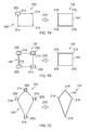
Figs 7A-7C illustrate computer-implemented virtual boundary definition/redefinition using movable craft; -
Figs 8A-8C illustrate computer-implemented virtual boundary definition using handover between movable crafts; -
Fig 9 illustrates an example of a method. - In this document the term "maneuver" when used as a noun in relation to one movable craft refers to a change in position of the movable craft over time and when used as a noun in relation to multiple movable craft relates to their relative positions at a moment in time or to a change in the positions or relative positions of one or more of the movable craft over time. If one considers that a set of space co-ordinates define a position at a particular time, a maneuver is defined by multiple different sets of space coordinates for one or more movable craft that define different positions in space. The term "maneuver" when used as a verb or adjective refers to the performance of a maneuver.
- In this document a "movable craft" is a conveyance, vehicle or other means of transport.
- In this document a "monitored scene space" or "scene space" or "scene" is a three dimensional space that is monitored.
- In this document a "monitoring space" is a virtual three dimensional space that corresponds to the monitored scene space and within which a computer-implemented virtual boundary is defined.
- In this document a "computer-implemented virtual boundary" is a boundary in the monitoring space, which is a computer-implemented virtual space.
- In this document an "event" is an occurrence.
- In this document a "response event" is an occurrence generated in response to a detected change in the monitored scene space.
- The
system 100 described is a system that monitors at least onescene 140. Ascene 140 is a space where an event may occur. Thescene 140 may consequentially also be referred to as a monitoredscene space 140. The operation of thesystem 100 can be controlled by one or more movable craft that maneuver within the monitoredscene space 140. For example, one or more movable craft can define at least one computer-implementedvirtual boundary 144 to be monitored by thesystem 100. -
Fig 1 schematically illustrates asystem 100 comprising: one ormore sensors 110 configured to recordsensor data 112 from ascene 140; aprocessing module 120 configured to process thesensor data 112 recorded from thescene 140 to recognize automatically events that occur in thescene 140 and to automatically take decisions as a consequence of the recognition; and acommunication module 130 configured to communicate, when a decision to communicate is taken by theprocessing module 120. - Some but not necessarily all of the events that are recognized may relate to an
object 152 or aparticular object 152 in thescene 140. An object may be an inanimate object, an animal, a person or a particular person in thescene 140. In some but not necessarily all examples of thesystem 100, thesystem 100 is a real-time recognition system and the automatic recognition and decision, if any, occur substantially at the same time as thesensor data 112 is recorded. - The
system 100 may enable a user to control monitoring, for example, from within thescene 140. Thesystem 100 may enable a user to control recognition and/or a consequence of recognition, for example, via motion of the user or other controllingobject 150 within the scene. The controllingobject 150 may be part of a person in thescene 140 or an object carried by a person or may be amovable craft 200 within thescene 140. - Examples of actions performed may be the generation of an alert or notification.
- In some but not necessarily all examples, the
system 100 may comprise a number of discrete apparatus. For example, thesensors 110 may be housed in one or more separate apparatus, theprocessing module 120 may be housed in one or more apparatus and thecommunication module 130 may be housed in one or more apparatus. Where a component or components of thesystem 100 are housed in discrete apparatus, those apparatus may be local or remote to each other and, where they are remote they may communicate, for example, over a network. - In some but not necessarily all examples, the
system 100 may be housed in a single apparatus. - The
sensors 110 are configured to record or enable recording ofsensor data 112 from thescene 140. - A
scene 140 may comprise static components that have, for example, fixed relative positions, such as for example static objects. These static objects have different static positions in the scene's three-dimensional space (scene space). Ascene 140 may comprise moving components, such as for example a moving object. A moving object has different positions in the scene space over time. Reference to 'the scene' in relation todifferent sensor data 112 or different times implies a continuity of those static components of thescene 140 that are sensed, it does not necessarily imply a continuity of some or all of the dynamic components although this may occur. - The recording of
sensor data 112 may comprise only temporary recording, or it may comprise permanent recording or it may comprise both temporary recording and permanent recording, Temporary recording implies the recording of data temporarily. This may, for example, occur during sensing, occur at a dynamic memory, occur at a buffer such as a circular buffer, a register, a cache or similar. Permanent recording implies that the data is in the form of an addressable data structure that is retrievable from an addressable memory space and can therefore be stored and retrieved until deleted or over-written, although long-term storage may or may not occur. - The
sensors 110 may be configured to transduce propagating waves, such as sound waves and/or light waves, to electrical signals encoding the propagating wave data from thescene 140 assensor data 112. - In some but not necessarily all examples, one or more of the
sensors 110 are fixed in space relative to thescene space 140. In other examples, which may be the same or different examples, one or more of thesensors 110 are movable or moving relative to thescene space 140. For example, one or more of thesensors 110 may be part of some, all or none of the one or moremovable craft 200. - In some, but not necessarily all embodiments, the
sensors 110 are or compriseimage sensors 114. An example of animage sensor 114 is a digital image sensor that is configured to operate as a camera. Such a camera may be operated to record static images and/or video images. - In some, but not necessarily all embodiments, cameras may be configured in a stereoscopic or other spatially distributed arrangement so that the
scene 140 is viewed from different perspectives. This may enable the creation of a three-dimensional image and/or processing to establish depth, for example, via the parallax effect. - In some, but not necessarily all embodiments, the
sensors 110 are or compriseaudio sensors 116. An example of anaudio sensor 116 is a microphone or microphones. Microphones may be configured in a stereoscopic or other spatially distributed arrangement such as a microphone array so that thescene 140 is sampled from different perspectives. This may enable three-dimensional spatial audio processing, that allows positioning of audio within thescene 140. - In some, but not necessarily all embodiments, the sensors are or comprise
depth sensors 118. Adepth sensor 118 may comprise a transmitter and a receiver. The transmitter transmits a signal (for example, a signal a human cannot sense such as ultrasound or infrared light) and the receiver receives the reflected signal. Using a single transmitter and a single receiver some depth information may be achieved via measuring the time of flight from transmission to reception. Better resolution may be achieved by using more transmitters and/or more receivers (spatial diversity). In one example, the transmitter is configured to 'paint' thescene 140 with light, preferably invisible light such as infrared light, with a spatially dependent pattern. Detection of a certain pattern by the receiver allows thescene 140 to be spatially resolved. The distance to the spatially resolved portion of thescene 140 may be determined by time of flight and/or stereoscopy (if the receiver is in a stereoscopic position relative to the transmitter). - In these 'passive' or 'non-active' examples of depth sensing are passive and merely reflect incident light or sound waves emitted by a transmitter. However, 'active' examples, which require activity at the sensed object, may additionally or alternatively be used.
- In the illustrated example, but not necessarily all examples, the
processing module 120 comprises amemory sub-module 122, aprocessing sub-module 124, arecognition sub-module 126, and acontrol sub-module 128. While the 'modules' are described and illustrated separately they may be, although they need not be, separate or combined in different combinations. For example, theprocessing sub-module 124, therecognition sub-module 126, and thecontrol sub-module 128 may be performed by the same circuitry or under the control of the same computer program. Alternatively one or more of theprocessing sub-module 124, therecognition sub-module 126, and thecontrol sub-module 128 may be performed by dedicated circuitry or a dedicated computer program. The sub-modules may be performed using software, dedicated hardware or a mix of programmed hardware and software. - The
memory sub-module 122 may be used to store unprocessed sensor data and/or processed sensor data 112 (scene data), computer programs, scene space models and other data used by theprocessing module 120, although other sub-modules may have their own memories. - The processing sub-module 124 may be configured to process the
sensor data 112 to determine scene data that is meaningful about thescene 140. - The processing sub-module 124 may be configured to perform image processing where the
sensor data 110 comprises image data from a camera orcameras 114. The processing sub-module 124 may be configured to perform audio processing where thesensor data 110 comprises audio data from a microphone ormicrophones 116. - The processing sub-module 124 may be configured to perform automatically one or more of the following tasks using the
sensor data 112 to create scene data that has potential meaning for the scene 140: - use machine (computer) vision to perform one or more of:
- detect a (moving or stationary) object or person,
- classify a (moving or stationary) object or person, and/or
- track a (moving or stationary) object or person;
- use spatial analysis to perform one or more of:
- position a (moving or stationary) object in the scene space using depth determination; and/or
- create a map of the scene space; and/or
scene 140 as a potentially meaningful symbol. - An example of image processing is 'histogram of gradient features' analysis which creates a distribution of intensity gradients or edge directions for an image. The image may be divided into small connected regions (cells), and for each cell, a histogram of gradient directions or edge orientations is created for the pixels within the cell. The combination of these histograms then represents a descriptor.
- An example of audio processing is 'mel-frequency cepstral coefficients' determination, spatial audio processing using, for example, audio beamforming techniques, audio event recognition or classification, speaker recognition or verification or speech recognition.
- Motion detection may be achieved, for example, using differencing with respect to a background model (background subtraction) or with respect to a preceding image (temporal differencing), or using some other approach such as optical flow analysis using a vector-based approach.
- Object classification may be achieved, for example, using shape-based analysis and/or motion-based analysis.
- Classification of a person may be classification that an object is human or classification that an object is a particular human (identification). Identification may be achieved using an attribute or a combination of attributes that uniquely identifies a person within the set of possible persons. Examples of attributes include: biometric features that are or may be particular to a person such as their face or their voice: their shape and size; their behavior.
- Object tracking may be achieved by labeling objects and recording the position in the
scene 140 of the labeled object. The algorithm may need to deal with one or more of the following events: object entrance to thescene 140; object exit from thescene 140; object re-entrance to thescene 140; object occlusion; object merge. How to deal with these events is known in the art. - Object tracking may be used to determine when an object or person changes. For example, tracking the object on a large macro-scale allows one to create a frame of reference that moves with the object. That frame of reference can then be used to track time-evolving changes of shape of the object, by using temporal differencing with respect to the object. This can be used to detect small scale human motion such as gestures, hand movement, facial movement. These are scene independent user (only) movements relative to the user.
- The system may track a plurality of objects and/or points in relation to a person's body, for example one or more joints of the person's body. In some examples, the
system 100 may perform full body skeletal tracking of a person's body. - The tracking of one or more objects and/or points in relation to a person's body may be used by the
system 100 in gesture recognition and so on. - Behavior analysis requires describing an event that occurs in the
scene 140 using a meaningful symbology. An event may be something that occurs at a spatio-temporal instance or it may be a spatio-temporal sequence (a pattern of spatio-temporal instances over time). An event may relate to motion of an object (or person) or interaction of a person and object. - In some, but not necessarily all implementations, an event may be represented by a putative symbol defined in terms of parameters determined from the machine (computer) vision analysis and/or the spatial analysis. These parameters encode some or more of what is happening, where it is happening, when it is happening and who is doing it.
- The
recognition sub-module 126 is configured to recognize a putative symbol encoding an event in thescene 140 as a meaningful symbol associated with a particular meaning. - The recognition sub-module 126 may be configured to recognize a putative symbol, defined in terms of parameters determined from the machine (computer) vision analysis and/or the spatial analysis, and produced by the
processing sub-module 124 as having meaning. The recognition sub-module 126 may, for example, store or access a database of meaningful reference symbols and may use a similarity test to determine whether a putative symbol is 'similar' to a meaningful symbol. - The recognition sub-module 126 may be configured as a machine (computer) inference engine or other recognition engine such as an artificial neural network or clustering in the parameter space. The recognition sub-module may 126, in some examples, be trained, via supervised learning, to recognize meaningful symbols as similar to reference symbols.
- The control sub-module 128 responds to the determination that a meaningful event has occurred in the
scene 140 in dependence on the event: - a) If the putative symbol is similar to a response symbol, the meaningful event is a 'response' event, and the
control sub-module 126 performs a response action. - In some but not necessarily all examples the action performed may be programmed by a user. In some but not necessarily all examples the programming may occur via motion of the user or other controlling
object 150 within the scene. Examples of actions performed may be the generation of an alert or notification. - The alert or notification may be provided via the
communications module 130. Thecommunications module 130 may communicate wirelessly, for example via radio waves or via a wired connection to a local or remote apparatus. Examples of such apparatus include but are not limited to displays, televisions, audio output apparatus, personal devices such as mobile telephone or personal computers, a projector or other user output apparatus. - In some but not necessarily all examples the response symbol may be programmed by a user. For example, a user may be able to program or teach a meaningful event that is represented by a meaningful response symbol. The response symbol, created by the user, may be added to the database of reference symbols or otherwise used to recognize a putative symbol as a meaningful symbol. In some but not necessarily all examples the programming may occur via motion of the user within the
scene 140. Examples of meaningful events that are represented by meaningful symbols include particular actions or movements performed such as user input gestures. - Action by a single person or collective action by many people may be used as a response symbol. In some but not necessarily all examples, a particular gesture user input or collection of gesture user inputs may be used a response symbol.
- b) If the putative symbol is similar to a control symbol, the meaningful event is a 'control' event, and the
control sub-module 126 enables control of monitoring and/or control of the response. - For example, a user may be able to program or teach a meaningful response symbol that is added to the database of reference symbols. In some but not necessarily all examples the programming may occur via motion of a
controlling object 150, for example a user or movable craft, within thescene 140. - For example, a user may be able to program or teach an action performed when the putative symbol is matched to a response symbol. Examples of actions performed may be the generation of an alert or notification.
- The operation of the
processing module 120 may be further understood fromFig 2 which illustrates astate machine 20 for theprocessing module 120. Thestate machine 20 has amonitoring state 21, acontrol state 22 and anautomatic response state 23. - In the
monitoring state 21, thesensors 110 providesensor data 112, and theprocessing sub-module 124 automatically processes the sensor data 112 (video and/or audio and/or depth) to create scene data that has potential meaning. The recognition sub-module 126 automatically processes the scene data to identify actual meaning, that is meaningful symbols, within the scene data. - The meaningful symbols are predetermined, that is actions have occurred that determine a symbol prior to recognition. However, 'predetermined' should not be considered to mean exact or fixed. The symbol used for similarity matching merely has prior determination, it may dynamically evolve or may be fixed.
- If the
recognition sub-module 126 determines that a meaningful event has occurred in thescene 140, thecontrol sub-module 126 responds automatically depending on the event. If the meaningful event is a 'response' event, then thestate machine 20 transitions to theresponse state 23 and thecontrol sub-module 126 performs a response action. The response action may be associated with the response event. If the event is a 'control' event, then thestate machine 20 transitions to thecontrol state 22 and control of monitoring and/or response is enabled. The enablement may be in a manner associated with thatcontrol state 22. - Action by a single person or collective action by many people may be used as a 'control' symbol. In some but not necessarily all examples, a particular gesture user input may be used a control symbol.
- In some examples, the
system 100 may track one or more objects and/or points in relation to a person's body in gesture recognition. For example, thesystem 100 may perform full skeletal tracking of a person's body in gesture recognition. - Implementation of the
processor module 120 or part of theprocessor module 120 may be as controller circuitry. Thecontroller circuitry 120 may be implemented in hardware alone, have certain aspects in software including firmware alone or can be a combination of hardware and software (including firmware). - As illustrated in
Fig 3 thecontroller 120 may be implemented using instructions that enable hardware functionality, for example, by using executablecomputer program instructions 322 in a general-purpose or special-purpose processor 310 that may be stored on a computer readable storage medium (disk, memory etc) to be executed by such aprocessor 310. - The
processor 310 is configured to read from and write to thememory 320. Theprocessor 310 may also comprise an output interface via which data and/or commands are output by theprocessor 310 and an input interface via which data and/or commands are input to theprocessor 310. - The
memory 320 stores acomputer program 322 comprising computer program instructions (computer program code) that controls the operation of theprocessing module 120 when loaded into theprocessor 310. The computer program instructions, of thecomputer program 322, provide the logic and routines that enables the processing module to perform the methods discussed with reference to the Figs. Theprocessor 310 by reading thememory 320 is able to load and execute thecomputer program 322. - The
system 100 may therefore comprise anapparatus 120 that comprises: - at least one
processor 310; and at least onememory 320 includingcomputer program code 322 the at least onememory 320 and thecomputer program code 322 configured to, with the at least oneprocessor 310, cause theapparatus 120 at least to perform one or more ofblocks Fig 1 and/or one or more of the blocks ofFig 8 . - As illustrated in
Fig 4 , thecomputer program 322 may arrive at such an apparatus via anysuitable delivery mechanism 324. Thedelivery mechanism 324 may be, for example, a non-transitory computer-readable storage medium, a computer program product, a memory device, a record medium such as a compact disc read-only memory (CD-ROM) or digital versatile disc (DVD), an article of manufacture that tangibly embodies thecomputer program 322. The delivery mechanism may be a signal configured to reliably transfer thecomputer program 322 such as a modulated electromagnetic wave or digitally encoded electrical signal. Theapparatus 120 may propagate or transmit thecomputer program 322 as a computer data signal. - Although the
memory 320 is illustrated as a single component/circuitry it may be implemented as one or more separate components/circuitry some or all of which may be integrated/removable and/or may provide permanent/semi-permanent/ dynamic/cached storage. - Although the
processor 310 is illustrated as a single component/circuitry it may be implemented as one or more separate components/circuitry some or all of which may be integrated/removable. Theprocessor 310 may be a single core or multi-core processor. - References to 'computer-readable storage medium', 'computer program product', 'tangibly embodied computer program' etc. or a 'controller', 'computer', 'processor' etc. should be understood to encompass not only computers having different architectures such as single /multi- processor architectures and sequential (Von Neumann)/parallel architectures but also specialized circuits such as field-programmable gate arrays (FPGA), application specific circuits (ASIC), signal processing devices and other processing circuitry. References to computer program, instructions, code etc. should be understood to encompass software for a programmable processor or firmware such as, for example, the programmable content of a hardware device whether instructions for a processor, or configuration settings for a fixed-function device, gate array or programmable logic device etc.
- As used in this application, the term 'circuitry' refers to all of the following:
- (a) hardware-only circuit implementations (such as implementations in only analog and/or digital circuitry) and
- (b) to combinations of circuits and software (and/or firmware), such as (as applicable): (i) to a combination of processor(s) or (ii) to portions of processor(s)/software (including digital signal processor(s)), software, and memory(ies) that work together to cause an apparatus, such as a mobile phone or server, to perform various functions) and
- (c) to circuits, such as a microprocessor(s) or a portion of a microprocessor(s), that require software or firmware for operation, even if the software or firmware is not physically present.
- This definition of 'circuitry' applies to all uses of this term in this application, including in any claims. As a further example, as used in this application, the term "circuitry" would also cover an implementation of merely a processor (or multiple processors) or portion of a processor and its (or their) accompanying software and/or firmware. The term "circuitry" would also cover, for example and if applicable to the particular claim element, a baseband integrated circuit or applications processor integrated circuit for a mobile phone or a similar integrated circuit in a server, a cellular network device, or other network device.
- The
blocks Fig 1 and/or the blocks illustrated inFig 9 may represent steps in a method and/or sections of code in thecomputer program 322. The illustration of a particular order to the blocks does not necessarily imply that there is a required or preferred order for the blocks and the order and arrangement of the block may be varied. Furthermore, it may be possible for some blocks to be omitted. - In some but not necessarily all examples the controlling
object 150 may be a user, for example, aperson 150 in thescene 140. In some but not necessarily all examples, which may be the same or different examples, the controllingobject 150 may be one or moremovable craft 200. In some but not necessarily all examples, themovable craft 200 may be an aircraft, One example of amovable craft 200 is a 'drone'. A drone Is a pilotless radio-controlled craft. An aircraft drone Is a pilotless radio-controlled aircraft. -
Fig 5 illustrates an example of adrone 200. In this example, but not necessarily all examples, the drone is an aircraft drone. Theaircraft drone 200 comprises apropulsion system 202 for moving theaircraft drone 200 in three dimensions. - The positioning or re-positioning of the aircraft drone may be performed by a user manually or via voice control, semi-autonomously or autonomously. The position of the
aircraft drone 200 may in some examples be defined by position only, in other examples by orientation only and in other examples by both position and orientation. Thus in some but not necessarily all examples, the aircraft drone may, be autonomous, semi-autonomous or entirely user-controlled at changing its three dimensional position and/or a three-dimensional orientation. - The term 'fully-autonomous' when used to describe a function means that the craft can perform the function according to pre-defined rules without the need for any real-time user input. The real-time control is entirely rule-based.
- The term 'semi-autonomous' when used to describe a function means that the craft can perform the function according to pre-defined rules but additionally requires some real-time user input. The real-time control is not entirely rule-based and not entirely under the control of a user.
- The term 'autonomous' encompasses both 'fully-autonomous' and "semi-autonomous'. Where a feature is described as 'autonomous' it may be 'fully-autonomous' or "semi-autonomous'.
- The
aircraft drone 200 may optionally comprise an autonomous position stability system 204. The autonomous position stability system 204 controls thepropulsion system 202 to maintain theaircraft drone 200 at a particular three dimensional position. The maintained three dimensional position may, for example, be an absolute position defined in a co-ordinate system fixed to the earth or the maintained three dimensional position may, for example, be a relative position defined in a co-ordinate system that moves, for example with a trackedobject 152 in the monitoredscene space 140. The trackedobject 152 may, for example, be anotheraircraft drone 200. - The
aircraft drone 200 may optionally comprise an autonomousorientation stability system 206. The autonomousorientation stability system 206 controls thepropulsion system 202 to maintain theaircraft drone 200 at a particular three dimensional orientation. The maintained three dimensional orientation may, for example, be an absolute orientation defined in a co-ordinate system fixed to the earth or the maintained three dimensional orientation may, for example, be a relative orientation defined in a co-ordinate system that moves, for example with a trackedobject 152 in the monitoredscene space 140. The trackedobject 152 may, for example, be anotheraircraft drone 200. - The
aircraft drone 200 may optionally comprise awireless communications system 208 for communicating with acommunications module 130 of thesystem 100. - The
aircraft drone 200 may optionally comprise anavigation system 210 for enabling position of theaircraft drone 200 in three dimensions, for example, via satellite position or some other position technology. In some examples, a position of theaircraft drone 200 is communicated to thesystem 100. Thenavigation system 210 may also enable planning of a route followed by theaircraft drone 200 and/or provide an input to the position stability system 204 and/or thepropulsion system 202 - The
aircraft drone 200 may optionally comprisekinematic sensors 212 for enabling detection of changes in position and/or orientation using, for example, an electronic compass, gyroscopes, magnetometers and accelerometers along different axes. Thesekinematic sensors 212 may provide input to the position stability system 204 and/or theorientation stability system 206. - The
aircraft drone 200 may optionally comprise at least some of thesensors 110 configured to monitor the monitoredscene space 140. Thesensors 110 are configured to record or enable recording ofsensor data 112 from thescene 140. - The
aircraft drone 200 may be configured to operate outdoors. For example, theaircraft drone 200 may be configured to operate in wind and rain. The aircraft drone may be waterproofed. - The
aircraft drone 200 may, for example, be used to define a computer-implemented virtual boundary outdoors, over a large area of tens, hundreds or thousands of meters and/or extending to a high altitude. This may be particularly useful at large scale outdoor events such as concerts, festivals, sports events, areas where crowd control is required or areas where surveillance is required. -
Fig 6 illustrates an example of operation of thesystem 100. Part A illustrates real-world scene within a three-dimensional space monitored by thesystem 100. Thescene 140 may also be referred to as a monitoredscene space 140. - In the example of
Fig 6 amovable craft 200, for example an aircraft drone, is performing amaneuver 146 to define at least one computer-implementedvirtual boundary 144. - In the illustrated example the
movable craft 200 is performing a maneuver to define a single computer-implemented virtual boundary 144.Themaneuver 148 comprise any motion or series of motions in one spatial dimension, two spatial dimensions or three spatial dimensions and may take any form. - Part C of the example of
Fig 6 illustrates an overhead view of the monitoredscene space 140 in which themovable craft 200 is illustrated making themaneuver 146 to define the computer-implementedvirtual boundary 144. - As can be seen in parts A and C of the example of
Fig 6 , themaneuver 146 has a position having Cartesian orthogonal coordinates (xi(t), yi(t), zi(t)) in thescene 140 for each user input object i, at time t. In this example, xi(t) is measured from the left, yi(t) is measured from the front and zi(t) is measured from the bottom. It will be understood that other coordinate systems may be used and that different orientations of the Cartesian coordinate system may be used - For simplicity of illustration in
Fig 6 , themaneuver 146 comprises motion of onemovable craft 200 in one spatial dimension as the value of x changes and the values of y and z remain constant. In other examples the values of x, y and/or z may vary in any way withmovement 148 from any starting position in the monitoredscene space 140. Also multiplemovable craft 200 may be used, for example, simultaneously. - Parts B and D of the example of
Fig 6 illustrate amonitoring space 142 that corresponds to the monitored scene space 140 (a corresponding monitoring space 142). Themonitoring space 142 comprises a virtual representation of the monitoredscene space 140 created and used by thesystem 100. Themonitoring space 142 may be formed, for example, from data received by thesensors 110, such as received image data and/or depth data. Parts B and D illustrate respectively the same views as illustrated in parts A and C ofFig 6 . - In some examples the
system 100 may use information of the geometry of the monitoredscene space 140 to form themonitoring space 142. For example, thesystem 100 may use a three dimensional model of the monitoredscene space 140 in the formation of themonitoring space 142. The three dimensional model of the monitoredscene space 140 may be created by thesystem 100 and/or may be received by thesystem 100. Methods for creating a three dimensional model of the monitoredscene space 140 are known in the art. - The
system 100 may use themonitoring space 142 to monitor thescene space 140. For example, the system may use themonitoring space 142 to implement and monitor at least one computer-implementedvirtual boundary 144. - As indicated by the arrows between parts A and B and parts C and D of
Fig 6 there is a correspondence between themonitoring space 142 and the monitoredscene space 140. In some examples there may be a one to one mapping M between themonitoring space 142 and the monitoredscene space 140. - In other examples there may be a scale invariant transformation between the monitored
scene space 140 and themonitoring space 142. - The
system 100 recognizes themaneuver 146 performed by themovable craft 200 and in response implements at least one computer-implementedvirtual boundary 144 in themonitoring space 142. - In some examples, recognizing the
maneuver 146 may comprise processing received data. In one example the received data may be image data that are analyzed to position themovable craft 200 using image processing. In another example the received data may comprise position data that positions themovable craft 200, which in some examples may be a position provided by a positioning system within themovable craft 200. - In examples, a shape and position of the computer-implemented
virtual boundary 144 in the monitoring space is determined, at least partially, by themaneuver 146 in the monitoredscene space 140 and the computer-implementedvirtual boundary 144 is located in the monitoring space at a corresponding position equivalent to the position of themaneuver 146 in the monitoredscene space 140. - It will therefore be understood that the
system 100 enables positioning of one or moremovable craft 200 in a monitoredscene space 140 to at least partially define a shape and position of a computer-implementedvirtual boundary 144 in acorresponding monitoring space 142; causing implementation of the computer-implementedvirtual boundary 144 in themonitoring space 142 corresponding to the monitoredscene space 140; and processing receiveddata 112 fromsensors 110 of the monitoredscene space 140 to generate a response event in response to a change in at least a portion of the monitoredscene space 140 relative to the computer-implementedvirtual boundary 144 in thecorresponding monitoring space 142. -
Figs 7A, 7B, 7C ,8A, 8B, 8C illustrate different examples of different positions of one or moremovable craft 200 in a monitoredscene space 140 that define 210 a shape and position of a computer-implementedvirtual boundary 144 in acorresponding monitoring space 142. - In some but not necessarily all examples it may be necessary for a
movable craft 200 to 'pair' with thesystem 100 to enable thatmovable craft 200 to control a shape and position of a computer-implementedvirtual boundary 144. The pairing may for example comprise an authentication procedure that identifies themovable craft 200 and/or an authorization procedure that checks one or more security credentials. - In these figures, a point pn(tx) refers to a
point 214 in the monitoredspace 140 at a time tx and defined by a movable craft n. A point pn(tx) corresponds to a particular point pn'(tx) 216 in the monitoredscene space 140, where the same label n is used consistently in both spaces to label correspondingpoints - The
maneuver 148 in the monitoredscene space 140 specifies a set of different points {pn(tx) } which map to a corresponding set of points {pn'(tx) } in themonitoring space 142. The mapping M that maps the monitoredscene space 140 to themonitoring space 142 also maps the set of different points {pn(tx) } in the monitoredscene space 140 to a corresponding set of different points {pn'(tx) } in themonitoring space 142. - The set of different points {pn'(tx) } in the
monitoring space 142 defines a shape and position of the computer-implementedvirtual boundary 144 in thecorresponding monitoring space 142. - In the example illustrated, the computer-implemented
virtual boundary 144 in the monitoring space passes through each of thepoints 216 in the set points {pn'(tx) } In the examples illustrated, the computer-implementedvirtual boundary 144 is an N-sided polygon having a vertex (angular point) at each of thepoints 216 in the set points {pn'(tx)}. - The computer-implemented
virtual boundary 144 may be one, two or three dimensional. - In
Fig 7A , a computer-implementedvirtual boundary 144 is defined 210 by amaneuver 148 comprising only movement of a singlemovable craft 200 in the monitoredscene space 140. The computer-implementedvirtual boundary 144 is defined 210 by the sequence ofpositions 214 of the singlemovable craft 200 in the monitoredscene space 140. Themovable craft 200 in the monitoredscene space 140 specifies a sequence ofpoints 214 in the monitoredscene space 140 which correspond topoints 216 in the monitoring space 143. The shape and position of the computer-implementedvirtual boundary 144 is defined by the position of thepoints 216 in themonitoring space 142. In this example, the computer-implementedvirtual boundary 144 is an N-sided polygon having N vertices (angular points) at thepoints 216. The singlemovable craft 200 in the monitoredscene space 140 defines, at eachposition 214, one of the N vertices. Themovable craft 200 may transmit a waypoint signal to identify to thesystem 100 that a waypoint on its journey specifies apoint 214. - As illustrated in
Fig 7A , themaneuver 148 in a monitoredscene space 140 defines points p1(t1), p1(t2), p1(t3), p1(t4) in the monitoredscene space 140. The points p1(t1), p1(t2) , p1(t3), p1(t4) in the monitoredscene space 140 determine 210 corresponding points p1'(t1), p1'(t2), p1'(t3), p1'(t4) 216 in themonitoring space 142. Thus, themaneuver 148 in the monitoredscene space 140 specifies the points p1'(t1), p1'(t2) , p1'(t3), p4' (t4) in themonitoring space 142, which define the computer-implementedvirtual boundary 144. - In
Fig 7B , a computer-implementedvirtual boundary 144 is defined by amaneuver 148 comprising simultaneous positioning of multiplemovable craft 200 in the monitoredscene space 140. The computer-implementedvirtual boundary 144 is defined 210 by thesimultaneous positions 214 of the multiplemovable craft 200 in the monitoredscene space 140. Themovable crafts 200 in the monitoredscene space 140 specify an arrangement ofpoints 214 in the monitoredscene space 140 which corresponds to an arrangement ofpoints 216 in themonitoring space 142. The shape and position of the computer-implementedvirtual boundary 144 is defined by the position of thepoints 216 in themonitoring space 142. In this example, the computer-implementedvirtual boundary 144 is an N-sided polygon having N vertices (angular points) at thepoints 216. Each of the differentmovable craft 200 in the monitoredscene space 140 defines one of the N vertices. Amovable craft 200 may transmit a waypoint signal to identify to thesystem 100 that a waypoint at this time on its journey specifies apoint 214 or that the waypoints of the multiplemovable craft 200 at this time on their journey specify thepoints 214. - As illustrated in
Fig 7B , themaneuver 148 in a monitoredscene space 140 defines points p1(t1), p2(t1), p3(t1), p4(t1) in the monitoredscene space 140. As illustrated inFig 7B , the points p1(t1), p2(t1) , p3(t1), p4(t1) in the monitoredscene space 140 determine corresponding points p1'(t1), p2'(t1), p3'(t1), p4' (t1) in themonitoring space 142. Thus, themaneuver 148 in the monitoredscene space 140 specifies the points p1'(t1), p2'(t1), p3'(t1), p4'(t1) in themonitoring space 142, which define the computer-implementedvirtual boundary 144. - In another example (not separately illustrated), a computer-implemented
virtual boundary 144 is defined by amaneuver 148 comprising simultaneous positioning of a first set of one or moremovable craft 200 in the monitored scene space 140 (as inFig 7B ) and, in addition, movement of a second set of one or moremovable craft 200 in the monitored scene space 140 (as inFig 7A ). The computer-implementedvirtual boundary 144 is defined 210, in part, by thesimultaneous positions 214 of the first set of multiplemovable craft 200 and, in part, by the sequence ofpositions 214 of the second set ofmovable craft 200 in the monitoredscene space 140. The first set ofmovable craft 200 in the monitoredscene space 140 specify an arrangement of a first set ofpoints 214 in the monitoredscene space 140 which corresponds to an arrangement ofpoints 216 in themonitoring space 142. The shape and position of a first part or first parts of the computer-implementedvirtual boundary 144 is defined by the position of the first set ofpoints 216 in themonitoring space 142. The second set ofmovable craft 200 in the monitoredscene space 140 specifies one or more sequences ofpoints 214 in the monitoredscene space 140 which correspond to a second set ofpoints 216 in the monitoring space 143. The shape and position of a second part or second parts of the computer-implementedvirtual boundary 144 is defined by the position of the second set ofpoints 216 in themonitoring space 142. In some examples, the computer-implementedvirtual boundary 144 is an N-sided polygon having N vertices (angular points) at the first and second set ofpoints 216. Themovable craft 200 may transmit waypoint signals to identify to thesystem 100 that a waypoint at this time on its journey specifies apoint 214. - Dynamic modification of the computer-implemented
virtual boundary 144 is possible. InFig 7C , the computer-implementedvirtual boundary 144 as defined inFig 7B is redefined by anew maneuver 148 comprising re-positioning of one or moremovable craft 200 in the monitoredscene space 140. The computer-implementedvirtual boundary 144 is redefined 210 by thenew positions 214 of the multiplemovable craft 200 in the monitoredscene space 140. Themovable crafts 200 in the monitoredscene space 140 specify a new arrangement ofpoints 214 in the monitoredscene space 140 which corresponds to a new arrangement ofpoints 216 in themonitoring space 142. The new shape and position of the computer-implementedvirtual boundary 144 is defined by the new positions of thepoints 216 in themonitoring space 142. In this example, the computer-implementedvirtual boundary 144 is an N-sided polygon having N vertices (angular points) at thepoints 216. Each of the differentmovable craft 200 in the monitoredscene space 140 redefines one of the N vertices. Amovable craft 200 may transmit a waypoint signal to identify to thesystem 100 that a waypoint at this time on its journey specifies apoint 214 or that the waypoints of the multiplemovable craft 200 at this time on their journey specify thepoints 214. - As illustrated in
Fig 7C , themaneuver 148 in a monitoredscene space 140 defines points p1(t2), p2(t2), p3(t2), p4(t2) in the monitoredscene space 140. As illustrated inFig 7C , the points p1(t2), p2(t2), p3(t2), p4(t2) in the monitoredscene space 140 determine corresponding points p1'(t2), p2'(t2), p3'(t2), p4' (t2) in themonitoring space 142. Thus, themaneuver 148 in the monitoredscene space 140 specifies the points p1'(t2), p2'(t2), p3'(t2), p4'(t2) in themonitoring space 142, which redefine the computer-implementedvirtual boundary 144. - The
maneuver 148, for example as described with reference toFigs 7A, 7B, 7C , may be autonomous, semi-autonomous or user controlled. - For example, a user may specify a size of the computer-implemented
virtual boundary 144. The user may define a fixed size. The user may define rules that control re-sizing of the computer-implementedvirtual boundary 144 autonomously. - For example, a user may specify a shape of the computer-implemented
virtual boundary 144. The user may define a fixed shape. The user may define rules that control re-sizing of the computer-implementedvirtual boundary 144 autonomously. This may, for example, occur when more or lessmovable craft 200 are available for use. - For example, a user may specify a position of the computer-implemented
virtual boundary 144. The user may define a fixed absolute position or a fixed relative position relative to a user-specified tracked object. The user may define rules that control re-positioning of the computer-implementedvirtual boundary 144 autonomously. This may, for example, occur when a tracked object or objects change position or when other contextual factors change such as a position of the sun. - The user control provided to enable user specification of a feature of a computer-implemented
virtual boundary 144 or a rule that controls a feature of a computer-implementedvirtual boundary 144, may be by any suitable means. For example, the user may be able to provide user input commands to the multiplemovable craft 200, via thesystem 100 using for example gesture control, a touch screen interface, a programming interface, voice commands or similar. -
Figs 8A, 8B and 8C illustrate a handover procedure from a firstmovable craft 2001 to a secondmovable craft 2002. Before the handover, the firstmovable craft 2001 is used to define a computer-implementedvirtual boundary 144. After the handover, the firstmovable craft 2001 is no longer used to define the computer-implementedvirtual boundary 144 and the secondmovable craft 2002 is used to define the computer-implementedvirtual boundary 144. - In these figures, a computer-implemented
virtual boundary 144 is defined by amaneuver 148 comprising simultaneous positioning of multiplemovable craft 200 in the monitoredscene space 140. The computer-implementedvirtual boundary 144 is defined 210 by thesimultaneous positions 214 of the multiplemovable craft 200 in the monitoredscene space 140. Themovable crafts 200 in the monitoredscene space 140 specify an arrangement ofpoints 214 in the monitoredscene space 140 which corresponds to an arrangement ofpoints 216 in themonitoring space 142. The shape and position of the computer-implementedvirtual boundary 144 is defined by the position of thepoints 216 in themonitoring space 142. In this example, the computer-implementedvirtual boundary 144 is an N-sided polygon having N vertices (angular points) at thepoints 216. Each of the differentmovable craft 200 in the monitoredscene space 140 defines one of the N vertices. Amovable craft 200 may transmit a waypoint signal to identify to thesystem 100 that a waypoint at this time on its journey specifies apoint 214 or that the waypoints of the multiplemovable craft 200 at this time on their journey specify thepoints 214. - The
maneuver 148 in a monitoredscene space 140 defines points p1(t1), p2(t1), p3(t1), p4(t1) in the monitoredscene space 140. - As illustrated in
Fig 8A , beforehandover 300, the points p1(t1), +p2(t1), p3(t1), p4(t1) in the monitoredscene space 140 determine corresponding points p1'(t1), p2'(t1), p3'(t1), p4' (t1) in themonitoring space 142, which define the computer-implementedvirtual boundary 144. The firstmovable craft 2001 is associated with position p2(t1) and defines at least part of the computer-implementedvirtual boundary 144. The secondmovable craft 2002 is associated with position p5(t1) and does not define any part of the computer-implementedvirtual boundary 144. - As illustrated in
Fig 8B , afterhandover 300, the points p1(t2), p5(t2), p3(t2), p4(t2) in the monitoredscene space 140 determine corresponding points p1'(t2), p5'(t2), p3'(t2), p4' (t2) in themonitoring space 142, which define the computer-implementedvirtual boundary 144. The firstmovable craft 2001, associated with position p2(t1), no longer defines any part of the computer-implementedvirtual boundary 144. The secondmovable craft 2002, associated with position p5(t2), defines part of the computer-implementedvirtual boundary 144. - In the example illustrated in
Fig 8C , but not necessarily all examples, next afterhandover 300, the secondmovable craft 2002, associated with position p5(t), changesposition 302 so that its position p5(t3) = p2(t1). That it, the secondmovable craft 2002 occupies thesame position 214 as the firstmovable craft 2001 did before handover. 300. The points p1(t3), p5(t3), p3(t3), p4(t3) in the monitoredscene space 140 determine corresponding points p1'(t3), p5'(t3), p3'(t3), p4' (t3) in themonitoring space 142, which define the computer-implementedvirtual boundary 144. The computer-implementedvirtual boundary 144 at time t3 is the same as the computer-implementedvirtual boundary 144 at time t1, however, it is now defined by the secondmovable craft 2002 and not by the firstmovable craft 2001. - The
handover 300 betweenmovable craft 200 may be automatic. For example, if a battery used by the firstmovable craft 2001 discharges below a threshold level, it may transmit a replacement signal. The secondmovable craft 2002 in response to the replacement signal approaches the firstmovable craft 2001 and performs ahandover 300 with the firstmovable craft 2001. - The
handover 300 may additional involve thesystem 100 so that communications from thesystem 100 to the firstmovable craft 2001 change to communications from thesystem 100 to the secondmovable craft 2002. It may, for example, be necessary for thesystem 100 to de-pair with the firstmovable craft 2001 and pair with the secondmovable craft 2002. - Thus, the
system 100 at time t1, positions the firstmovable craft 2001 in the monitoredscene space 140 to at least partially define a shape and position of a computer-implementedvirtual boundary 144 in acorresponding monitoring space 142 and causes implementation of the computer-implementedvirtual boundary 144 in themonitoring space 142 corresponding to the monitoredscene space 140. Thesystem 100 processes receiveddata 112 fromsensors 110 of the monitoredscene space 140 to enable generation of a response event in response to a change in at least a portion of the monitoredscene space 140 relative to the computer-implementedvirtual boundary 144 in thecorresponding monitoring space 142. - The
system 100 between time t1 and time t2, recognizes ahandover 300 from the firstmovable craft 2001 to a secondmovable craft 2002. - The
system 100 at time t2, positions the secondmovable craft 2002 in the monitoredscene space 140 to at least partially define a new computer-implementedvirtual boundary 144 in thecorresponding monitoring space 142; and processes receiveddata 112 fromsensors 110 of the monitoredscene space 140 to enable generation of a response event in response to a change in at least a portion of the monitoredscene space 140 relative to the new computer-implementedvirtual boundary 144 in thecorresponding monitoring space 142. - In the above example a
handover 300 is used to replace onemovable craft 200 with another. In other examples one or more movable craft may be added increasing N or removed decreasing N. - In other examples one or more different computer-implemented boundaries may be combined to define a new computer-implemented
boundary 214. - The
system 100 may provide feedback to a user to confirm that thesystem 100 has recognized amaneuver 146 and has implemented computer-implementedboundary 144. The feedback may comprise any suitable feedback, for example audio and/or visual and/or tactile feedback and so on. Additionally or alternatively thesystem 100 may send one or more messages to a device or devices to inform the user that thesystem 100 has implemented computer-implementedboundary 144. - The
system 100, may process received data to generate a response event when there is, relative to the at least onevirtual boundary 144, a change in a portion of the monitoredscene space 140 that causes a change in a portion of themonitoring space 142 demarcated by computer-implemented boundary. - For example, the
system 100 may process data received by thesensors 110, such as audio and/or image data, to generate the response event. The system may analyze one or more audio and/or video feeds to generate the response event. In some examples processing the received data to generate the response event may be considered monitoring computer-implementedboundary 144. - In examples the same sensor, such as a camera, may be used in recognition of the
maneuver 146 defining the at least onevirtual boundary 144 and for monitoring the at least onevirtual boundary 144. - In some examples, processing received data to generate the response event may comprise processing received data to monitor computer-implemented
boundary 144 to detect activity across computer-implementedboundary 144 and/or activity within a threshold of computer-implementedboundary 144. For example, thesystem 100 may process audio and/or image and/or depth data to monitor computer-implementedboundary 144 to detect activity across computer-implementedboundary 144 or within a threshold of computer-implementedboundary 144. - The response event may comprise providing feedback, for example using the
communication module 130. In some examples the feedback may comprise one or more alerts. The one or more alerts may comprise any form of alert such as audio and/or visual alerts. Additionally or alternatively, the feedback may comprise providing one or more messages to an apparatus such as a mobile telephone, tablet, laptop computer, desktop computer and so on. - In some examples, the response event may additionally or alternatively comprise incrementing a counter. For example, the
system 100 may monitor the number of times there is a boundary interaction such as anobject 152 touching and/or crossing and/or approaching within a threshold of computer-implementedboundary 144. In addition or alternatively thesystem 100 may monitor the direction of boundary interactions, such as the direction of boundary crossings. Thesystem 100 may be configured to provide statistics on boundary interactions. - A user of the
system 100, may configure the response event. - The
system 100, in some examples, may process received data to generate a response event when there is, relative to computer-implementedboundary 144, a change in a portion of the monitoredscene space 140 in relation to anyobject 152. For example, the system may generate a response event when anyobject 152 crosses, touches and/or comes within a threshold of computer-implementedboundary 144. Suchvirtual boundaries 144 may be considered generalvirtual boundaries 144. - In other examples, the system may process received data to generate a response event when there is, relative to computer-implemented
boundary 144, a change in a portion of the monitoredscene space 140 in relation to one or more user specified objects 152. - For example, after defining the computer-implemented
virtual boundary 144, a user of thesystem 100 may indicate to thesystem 100 one ormore objects 152. Thesystem 100 in response thesystem 100 may generate a response event only when there is a change in a portion of the monitoredscene space 140, relative to computer-implementedboundary 144, in relation to the indicated objects 152. For example, thesystem 100 may generate a response event only when one of the indicatedobjects 152 crosses, touches and/or comes within a threshold of computer-implementedboundary 144. Suchvirtual boundaries 144 may be considered object specific virtual boundaries. - In some examples a computer-implemented
virtual boundary 144 may be conditionally monitored and/or conditionally enabled/disabled. For example, thesystem 100 may process received data to generate a response event when there is, relative to the computer-implementedvirtual boundary 144, a change in a portion of the monitoredscene space 140 when one or more criteria are satisfied but does not process received data to generate the response event otherwise. - The criteria may be predefined and/or may be configured by a user.
- In examples any criterion/criteria may be used. For example, any temporal and/or physical criteria may be used. In examples, a computer-implemented
virtual boundary 144 may be conditionally monitored dependent upon time of day and/or day of week and/or week of month and/or month of year and/or independence upon the presence of one ormore objects 152 in the monitoredscene space 140. -
Fig 9 illustrates an example of amethod 800. Themethod 800 may be performed by thesystem 100. Atblock 802, themethod 800 comprises: positioning one or moremovable craft 200 in a monitoredscene space 140 to at least partially define a shape and position of a computer-implementedvirtual boundary 144 in acorresponding monitoring space 142. Atblock 804, themethod 800 comprises: causing implementation of the computer-implementedvirtual boundary 144 in themonitoring space 142 corresponding to the monitoredscene space 140. Atblock 806, themethod 800 comprises: processing receiveddata 112 fromsensors 110 of the monitoredscene space 140 to generate a response event in response to a change in at least a portion of the monitoredscene space 140 relative to the computer-implementedvirtual boundary 144 in thecorresponding monitoring space 142. - Where a structural feature has been described, it may be replaced by means for performing one or more of the functions of the structural feature whether that function or those functions are explicitly or implicitly described.
- Examples of the disclosure provide for an easy and intuitive way to define virtual boundaries for a surveillance system.
- The term 'comprise' is used in this document with an inclusive not an exclusive meaning. That is any reference to X comprising Y indicates that X may comprise only one Y or may comprise more than one Y. If it is intended to use 'comprise' with an exclusive meaning then it will be made clear in the context by referring to "comprising only one.." or by using "consisting".
- In this brief description, reference has been made to various examples. The description of features or functions in relation to an example indicates that those features or functions are present in that example. The use of the term 'example' or 'for example' or 'may' in the text denotes, whether explicitly stated or not, that such features or functions are present in at least the described example, whether described as an example or not, and that they can be, but are not necessarily, present in some of or all other examples. Thus 'example', 'for example' or 'may' refers to a particular instance in a class of examples. A property of the instance can be a property of only that instance or a property of the class or a property of a subclass of the class that includes some but not all of the instances in the class. It is therefore implicitly disclosed that a features described with reference to one example but not with reference to another example, can where possible be used in that other example but does not necessarily have to be used in that other example.
- Although embodiments of the present invention have been described in the preceding paragraphs with reference to various examples, it should be appreciated that modifications to the examples given can be made without departing from the scope of the invention as claimed. Features described in the preceding description may be used in combinations other than the combinations explicitly described. Although functions have been described with reference to certain features, those functions may be performable by other features whether described or not. Although features have been described with reference to certain embodiments, those features may also be present in other embodiments whether described or not. Whilst endeavoring in the foregoing specification to draw attention to those features of the invention believed to be of particular importance it should be understood that the Applicant claims protection in respect of any patentable feature or combination of features hereinbefore referred to and/or shown in the drawings whether or not particular emphasis has been placed thereon.
Claims (15)
- A method comprising:positioning one or more movable craft in a monitored scene space to at least partially define a shape and position of a computer-implemented virtual boundary in a corresponding monitoring space;causing implementation of the computer-implemented virtual boundary in the monitoring space corresponding to the monitored scene space, andprocessing received data from sensors of the monitored scene space to generate a response event in response to a change in at least a portion of the monitored scene space relative to the computer-implemented virtual boundary in the corresponding monitoring space.
- A method as claimed in claim 1, wherein the movable craft is a drone.
- A method as claimed in claim 1 or 2, wherein the movable craft is an aircraft drone configured to autonomously maintain a three dimensional position and/or configured to autonomously maintain a three dimensional orientation.
- A method as claimed in claim 3 or 4, wherein the aircraft drone is configured to operate outdoors.
- A method as claimed in any preceding claim, wherein the one or more movable craft in the monitored scene space specifies points in the monitored scene space which correspond to points in the monitoring space , wherein a shape and position of the computer-implemented virtual boundary is at least partially defined by the points in the monitoring space.
- A method as claimed in any preceding claim, wherein the computer-implemented virtual boundary is an N-sided polygon having N vertices, wherein the one or more movable craft in the monitored scene space define the N vertices.
- A method as claimed in any preceding claim, wherein the computer-implemented virtual boundary is defined by movement of only a single movable craft in the monitored scene space.
- A method as claimed in any of claims 1 to 6, wherein the computer-implemented virtual boundary is defined by positions of multiple movable craft in the monitored scene space.
- A method as claimed in any preceding claim, wherein positioning the one or more movable craft comprises processing received data to track motion of the one or more movable craft in the monitored scene space.
- A method as claimed in any preceding claim , further comprising pairing with the one or more movable craft in the monitored scene space to enable positioning of the one or more movable craft in the monitored scene space and definition of a shape and position of the computer-implemented virtual boundary.
- A method as claimed in any preceding claim, further comprising recognizing at least one predetermined waypoint signal to allow a vertex in the computer-implemented virtual boundary to be recognized.
- A method as claimed in any preceding claim, wherein at least some of the sensors of the monitored scene space are part of the one or more movable craft
- A method as claimed in any preceding claim, wherein processing received data to generate a response event comprises processing image data to monitor the computer-implemented virtual boundary to detect activity across the computer-implemented virtual boundary and/or activity within a threshold of the computer-implemented virtual boundary.
- A method as claimed in any preceding claim further comprising:recognizing a handover from the first movable craft to a second movable craft;
positioning the second movable craft in the monitored scene space to at least partially define a new computer-implemented virtual boundary in the corresponding monitoring space; and
processing received data from sensors of the monitored scene space to enable generation of a response event in response to a change in at least a portion of the monitored scene space relative to the new computer-implemented virtual boundary in the corresponding monitoring space. - An apparatus comprising means for performing the method of at least one of claims 1 to 14 or a computer program , that when run by at least one processor, causes at least the method of at least one of claims 1 to 14 to be performed.
Priority Applications (8)
| Application Number | Priority Date | Filing Date | Title |
|---|---|---|---|
| EP15175986.7A EP3115978B1 (en) | 2015-07-09 | 2015-07-09 | Monitoring |
| ES15175986.7T ES2667096T3 (en) | 2015-07-09 | 2015-07-09 | Monitoring |
| PCT/FI2016/050492 WO2017005976A1 (en) | 2015-07-09 | 2016-07-05 | Monitoring |
| KR1020187004089A KR102096191B1 (en) | 2015-07-09 | 2016-07-05 | monitoring |
| CN201680040223.8A CN107851358B (en) | 2015-07-09 | 2016-07-05 | Method and apparatus for monitoring |
| US15/741,571 US10776631B2 (en) | 2015-07-09 | 2016-07-05 | Monitoring |
| JP2018500389A JP6705886B2 (en) | 2015-07-09 | 2016-07-05 | Surveillance |
| JP2019097229A JP2019198077A (en) | 2015-07-09 | 2019-05-24 | Monitoring |
Applications Claiming Priority (1)
| Application Number | Priority Date | Filing Date | Title |
|---|---|---|---|
| EP15175986.7A EP3115978B1 (en) | 2015-07-09 | 2015-07-09 | Monitoring |
Publications (2)
| Publication Number | Publication Date |
|---|---|
| EP3115978A1 true EP3115978A1 (en) | 2017-01-11 |
| EP3115978B1 EP3115978B1 (en) | 2018-03-07 |
Family
ID=53717885
Family Applications (1)
| Application Number | Title | Priority Date | Filing Date |
|---|---|---|---|
| EP15175986.7A Active EP3115978B1 (en) | 2015-07-09 | 2015-07-09 | Monitoring |
Country Status (7)
| Country | Link |
|---|---|
| US (1) | US10776631B2 (en) |
| EP (1) | EP3115978B1 (en) |
| JP (2) | JP6705886B2 (en) |
| KR (1) | KR102096191B1 (en) |
| CN (1) | CN107851358B (en) |
| ES (1) | ES2667096T3 (en) |
| WO (1) | WO2017005976A1 (en) |
Cited By (1)
| Publication number | Priority date | Publication date | Assignee | Title |
|---|---|---|---|---|
| US10776631B2 (en) | 2015-07-09 | 2020-09-15 | Nokia Technologies Oy | Monitoring |
Families Citing this family (4)
| Publication number | Priority date | Publication date | Assignee | Title |
|---|---|---|---|---|
| JP6302956B2 (en) * | 2016-06-15 | 2018-03-28 | 株式会社Subaru | Formation setting device, formation setting method and formation setting program |
| US11238281B1 (en) * | 2017-02-27 | 2022-02-01 | Amazon Technologies, Inc. | Light source detection in field of view |
| US10607406B2 (en) * | 2018-01-25 | 2020-03-31 | General Electric Company | Automated and adaptive three-dimensional robotic site surveying |
| CN111824406A (en) * | 2020-07-17 | 2020-10-27 | 南昌航空大学 | A public safety autonomous inspection quadrotor UAV based on machine vision |
Citations (3)
| Publication number | Priority date | Publication date | Assignee | Title |
|---|---|---|---|---|
| US20030179140A1 (en) * | 2002-03-19 | 2003-09-25 | Patterson Wade C. | Apparatus and method for keeping pets in a defined boundary having exclusion areas |
| US20060099969A1 (en) * | 2004-11-05 | 2006-05-11 | Houston Staton | Method and system to monitor persons utilizing wireless media |
| US20130180469A1 (en) * | 2010-05-18 | 2013-07-18 | Woodstream Corporation | Custom-shape wireless dog fence system and method with temperature compensated crystal oscillator for reduced clock speed variation between multiple base units and collar |
Family Cites Families (22)
| Publication number | Priority date | Publication date | Assignee | Title |
|---|---|---|---|---|
| JP2002211494A (en) * | 2001-01-17 | 2002-07-31 | Todaka Seisakusho:Kk | Flight scheduling device for unmanned helicopter |
| JP2004062611A (en) | 2002-07-30 | 2004-02-26 | Denso Corp | Vehicle anti-theft center and vehicle anti-theft device |
| JP2004106802A (en) | 2002-09-20 | 2004-04-08 | Nippon Telegr & Teleph Corp <Ntt> | Theft detection device and theft monitoring device |
| US7323982B2 (en) * | 2004-11-05 | 2008-01-29 | Wirelesswerx International, Inc. | Method and system to control movable entities |
| JP2006281830A (en) | 2005-03-31 | 2006-10-19 | Yamaha Motor Co Ltd | Camera viewpoint display system |
| JP2007099197A (en) | 2005-10-07 | 2007-04-19 | Toyota Motor Corp | Vehicle antitheft device |
| JP2008068710A (en) | 2006-09-13 | 2008-03-27 | Yamaha Motor Co Ltd | Data management method for unmanned helicopter |
| US9043052B2 (en) * | 2008-05-27 | 2015-05-26 | Wilfred So | System and method for multiple vehicles moving a common payload |
| JP5248292B2 (en) * | 2008-12-03 | 2013-07-31 | 株式会社東芝 | Search work support system and search work support method |
| US8779925B2 (en) | 2010-05-18 | 2014-07-15 | Woodstream Corporation | Custom-shape wireless dog fence system and method |
| CN102682627B (en) | 2012-05-04 | 2014-04-09 | 北京民航天宇科技发展有限公司 | General aviation flight monitoring airborne system based on ADS-B (Automatic Dependent Surveillance-Broadcast) |
| US9102406B2 (en) * | 2013-02-15 | 2015-08-11 | Disney Enterprises, Inc. | Controlling unmanned aerial vehicles as a flock to synchronize flight in aerial displays |
| US9075415B2 (en) * | 2013-03-11 | 2015-07-07 | Airphrame, Inc. | Unmanned aerial vehicle and methods for controlling same |
| WO2016057098A2 (en) * | 2014-07-15 | 2016-04-14 | Richard Postrel | System and method for automated traffic management of intelligent unmanned aerial vehicles |
| CN104156821A (en) | 2014-08-11 | 2014-11-19 | 江苏恒创软件有限公司 | Unmanned helicopter-based natural grassland animal husbandry management method |
| EP3037917B1 (en) | 2014-12-24 | 2021-05-19 | Nokia Technologies Oy | Monitoring |
| CN107531326B (en) * | 2015-03-12 | 2019-04-16 | 奈庭吉尔智慧系统公司 | Automated Unmanned Aerial Systems |
| EP3101511A1 (en) | 2015-06-03 | 2016-12-07 | Nokia Technologies Oy | Monitoring |
| EP3101629B1 (en) | 2015-06-04 | 2021-03-17 | Nokia Technologies Oy | Mediated reality |
| EP3115926A1 (en) | 2015-07-08 | 2017-01-11 | Nokia Technologies Oy | Method for control using recognition of two-hand gestures |
| EP3115870B1 (en) | 2015-07-09 | 2023-11-08 | Nokia Technologies Oy | Monitoring |
| EP3115978B1 (en) | 2015-07-09 | 2018-03-07 | Nokia Technologies Oy | Monitoring |
-
2015
- 2015-07-09 EP EP15175986.7A patent/EP3115978B1/en active Active
- 2015-07-09 ES ES15175986.7T patent/ES2667096T3/en active Active
-
2016
- 2016-07-05 CN CN201680040223.8A patent/CN107851358B/en active Active
- 2016-07-05 US US15/741,571 patent/US10776631B2/en active Active
- 2016-07-05 JP JP2018500389A patent/JP6705886B2/en active Active
- 2016-07-05 KR KR1020187004089A patent/KR102096191B1/en active Active
- 2016-07-05 WO PCT/FI2016/050492 patent/WO2017005976A1/en not_active Ceased
-
2019
- 2019-05-24 JP JP2019097229A patent/JP2019198077A/en active Pending
Patent Citations (3)
| Publication number | Priority date | Publication date | Assignee | Title |
|---|---|---|---|---|
| US20030179140A1 (en) * | 2002-03-19 | 2003-09-25 | Patterson Wade C. | Apparatus and method for keeping pets in a defined boundary having exclusion areas |
| US20060099969A1 (en) * | 2004-11-05 | 2006-05-11 | Houston Staton | Method and system to monitor persons utilizing wireless media |
| US20130180469A1 (en) * | 2010-05-18 | 2013-07-18 | Woodstream Corporation | Custom-shape wireless dog fence system and method with temperature compensated crystal oscillator for reduced clock speed variation between multiple base units and collar |
Cited By (1)
| Publication number | Priority date | Publication date | Assignee | Title |
|---|---|---|---|---|
| US10776631B2 (en) | 2015-07-09 | 2020-09-15 | Nokia Technologies Oy | Monitoring |
Also Published As
| Publication number | Publication date |
|---|---|
| US20180197015A1 (en) | 2018-07-12 |
| WO2017005976A1 (en) | 2017-01-12 |
| JP2019198077A (en) | 2019-11-14 |
| JP2018523231A (en) | 2018-08-16 |
| ES2667096T3 (en) | 2018-05-09 |
| KR102096191B1 (en) | 2020-04-02 |
| EP3115978B1 (en) | 2018-03-07 |
| CN107851358B (en) | 2019-09-17 |
| CN107851358A (en) | 2018-03-27 |
| US10776631B2 (en) | 2020-09-15 |
| JP6705886B2 (en) | 2020-06-03 |
| KR20180031013A (en) | 2018-03-27 |
Similar Documents
| Publication | Publication Date | Title |
|---|---|---|
| US10402984B2 (en) | Monitoring | |
| US11429189B2 (en) | Monitoring | |
| US10540543B2 (en) | Human-computer-interaction through scene space monitoring | |
| US10936880B2 (en) | Surveillance | |
| KR20190062171A (en) | Deep learning-based real-time detection and correction of compromised sensors in autonomous machines | |
| US10776631B2 (en) | Monitoring | |
| EP3115870B1 (en) | Monitoring | |
| JP2018523231A5 (en) | ||
| US10444852B2 (en) | Method and apparatus for monitoring in a monitoring space | |
| Jain et al. | Practical matters in computer vision | |
| HK40031420A (en) | Image processing method and apparatus, device and storage medium | |
| HK40031420B (en) | Image processing method and apparatus, device and storage medium |
Legal Events
| Date | Code | Title | Description |
|---|---|---|---|
| PUAI | Public reference made under article 153(3) epc to a published international application that has entered the european phase |
Free format text: ORIGINAL CODE: 0009012 |
|
| AK | Designated contracting states |
Kind code of ref document: A1 Designated state(s): AL AT BE BG CH CY CZ DE DK EE ES FI FR GB GR HR HU IE IS IT LI LT LU LV MC MK MT NL NO PL PT RO RS SE SI SK SM TR |
|
| AX | Request for extension of the european patent |
Extension state: BA ME |
|
| 17P | Request for examination filed |
Effective date: 20170711 |
|
| RBV | Designated contracting states (corrected) |
Designated state(s): AL AT BE BG CH CY CZ DE DK EE ES FI FR GB GR HR HU IE IS IT LI LT LU LV MC MK MT NL NO PL PT RO RS SE SI SK SM TR |
|
| REG | Reference to a national code |
Ref country code: DE Ref legal event code: R079 Ref document number: 602015008542 Country of ref document: DE Free format text: PREVIOUS MAIN CLASS: G08B0021020000 Ipc: G06K0009000000 |
|
| GRAP | Despatch of communication of intention to grant a patent |
Free format text: ORIGINAL CODE: EPIDOSNIGR1 |
|
| RIC1 | Information provided on ipc code assigned before grant |
Ipc: G06K 9/20 20060101ALI20171013BHEP Ipc: G06K 9/00 20060101AFI20171013BHEP Ipc: G05D 1/10 20060101ALI20171013BHEP Ipc: G05D 1/00 20060101ALI20171013BHEP |
|
| INTG | Intention to grant announced |
Effective date: 20171109 |
|
| GRAS | Grant fee paid |
Free format text: ORIGINAL CODE: EPIDOSNIGR3 |
|
| GRAA | (expected) grant |
Free format text: ORIGINAL CODE: 0009210 |
|
| AK | Designated contracting states |
Kind code of ref document: B1 Designated state(s): AL AT BE BG CH CY CZ DE DK EE ES FI FR GB GR HR HU IE IS IT LI LT LU LV MC MK MT NL NO PL PT RO RS SE SI SK SM TR |
|
| REG | Reference to a national code |
Ref country code: GB Ref legal event code: FG4D |
|
| REG | Reference to a national code |
Ref country code: CH Ref legal event code: EP Ref country code: AT Ref legal event code: REF Ref document number: 977322 Country of ref document: AT Kind code of ref document: T Effective date: 20180315 |
|
| REG | Reference to a national code |
Ref country code: IE Ref legal event code: FG4D |
|
| REG | Reference to a national code |
Ref country code: DE Ref legal event code: R096 Ref document number: 602015008542 Country of ref document: DE |
|
| REG | Reference to a national code |
Ref country code: ES Ref legal event code: FG2A Ref document number: 2667096 Country of ref document: ES Kind code of ref document: T3 Effective date: 20180509 Ref country code: NL Ref legal event code: FP |
|
| REG | Reference to a national code |
Ref country code: FR Ref legal event code: PLFP Year of fee payment: 4 |
|
| REG | Reference to a national code |
Ref country code: LT Ref legal event code: MG4D |
|
| PG25 | Lapsed in a contracting state [announced via postgrant information from national office to epo] |
Ref country code: NO Free format text: LAPSE BECAUSE OF FAILURE TO SUBMIT A TRANSLATION OF THE DESCRIPTION OR TO PAY THE FEE WITHIN THE PRESCRIBED TIME-LIMIT Effective date: 20180607 Ref country code: FI Free format text: LAPSE BECAUSE OF FAILURE TO SUBMIT A TRANSLATION OF THE DESCRIPTION OR TO PAY THE FEE WITHIN THE PRESCRIBED TIME-LIMIT Effective date: 20180307 Ref country code: CY Free format text: LAPSE BECAUSE OF FAILURE TO SUBMIT A TRANSLATION OF THE DESCRIPTION OR TO PAY THE FEE WITHIN THE PRESCRIBED TIME-LIMIT Effective date: 20180307 Ref country code: HR Free format text: LAPSE BECAUSE OF FAILURE TO SUBMIT A TRANSLATION OF THE DESCRIPTION OR TO PAY THE FEE WITHIN THE PRESCRIBED TIME-LIMIT Effective date: 20180307 Ref country code: LT Free format text: LAPSE BECAUSE OF FAILURE TO SUBMIT A TRANSLATION OF THE DESCRIPTION OR TO PAY THE FEE WITHIN THE PRESCRIBED TIME-LIMIT Effective date: 20180307 |
|
| REG | Reference to a national code |
Ref country code: AT Ref legal event code: MK05 Ref document number: 977322 Country of ref document: AT Kind code of ref document: T Effective date: 20180307 |
|
| PG25 | Lapsed in a contracting state [announced via postgrant information from national office to epo] |
Ref country code: GR Free format text: LAPSE BECAUSE OF FAILURE TO SUBMIT A TRANSLATION OF THE DESCRIPTION OR TO PAY THE FEE WITHIN THE PRESCRIBED TIME-LIMIT Effective date: 20180608 Ref country code: SE Free format text: LAPSE BECAUSE OF FAILURE TO SUBMIT A TRANSLATION OF THE DESCRIPTION OR TO PAY THE FEE WITHIN THE PRESCRIBED TIME-LIMIT Effective date: 20180307 Ref country code: LV Free format text: LAPSE BECAUSE OF FAILURE TO SUBMIT A TRANSLATION OF THE DESCRIPTION OR TO PAY THE FEE WITHIN THE PRESCRIBED TIME-LIMIT Effective date: 20180307 Ref country code: BG Free format text: LAPSE BECAUSE OF FAILURE TO SUBMIT A TRANSLATION OF THE DESCRIPTION OR TO PAY THE FEE WITHIN THE PRESCRIBED TIME-LIMIT Effective date: 20180607 Ref country code: RS Free format text: LAPSE BECAUSE OF FAILURE TO SUBMIT A TRANSLATION OF THE DESCRIPTION OR TO PAY THE FEE WITHIN THE PRESCRIBED TIME-LIMIT Effective date: 20180307 |
|
| PG25 | Lapsed in a contracting state [announced via postgrant information from national office to epo] |
Ref country code: PL Free format text: LAPSE BECAUSE OF FAILURE TO SUBMIT A TRANSLATION OF THE DESCRIPTION OR TO PAY THE FEE WITHIN THE PRESCRIBED TIME-LIMIT Effective date: 20180307 Ref country code: AL Free format text: LAPSE BECAUSE OF FAILURE TO SUBMIT A TRANSLATION OF THE DESCRIPTION OR TO PAY THE FEE WITHIN THE PRESCRIBED TIME-LIMIT Effective date: 20180307 Ref country code: IT Free format text: LAPSE BECAUSE OF FAILURE TO SUBMIT A TRANSLATION OF THE DESCRIPTION OR TO PAY THE FEE WITHIN THE PRESCRIBED TIME-LIMIT Effective date: 20180307 Ref country code: RO Free format text: LAPSE BECAUSE OF FAILURE TO SUBMIT A TRANSLATION OF THE DESCRIPTION OR TO PAY THE FEE WITHIN THE PRESCRIBED TIME-LIMIT Effective date: 20180307 Ref country code: EE Free format text: LAPSE BECAUSE OF FAILURE TO SUBMIT A TRANSLATION OF THE DESCRIPTION OR TO PAY THE FEE WITHIN THE PRESCRIBED TIME-LIMIT Effective date: 20180307 |
|
| PG25 | Lapsed in a contracting state [announced via postgrant information from national office to epo] |
Ref country code: CZ Free format text: LAPSE BECAUSE OF FAILURE TO SUBMIT A TRANSLATION OF THE DESCRIPTION OR TO PAY THE FEE WITHIN THE PRESCRIBED TIME-LIMIT Effective date: 20180307 Ref country code: AT Free format text: LAPSE BECAUSE OF FAILURE TO SUBMIT A TRANSLATION OF THE DESCRIPTION OR TO PAY THE FEE WITHIN THE PRESCRIBED TIME-LIMIT Effective date: 20180307 Ref country code: SM Free format text: LAPSE BECAUSE OF FAILURE TO SUBMIT A TRANSLATION OF THE DESCRIPTION OR TO PAY THE FEE WITHIN THE PRESCRIBED TIME-LIMIT Effective date: 20180307 Ref country code: SK Free format text: LAPSE BECAUSE OF FAILURE TO SUBMIT A TRANSLATION OF THE DESCRIPTION OR TO PAY THE FEE WITHIN THE PRESCRIBED TIME-LIMIT Effective date: 20180307 |
|
| REG | Reference to a national code |
Ref country code: DE Ref legal event code: R097 Ref document number: 602015008542 Country of ref document: DE |
|
| PG25 | Lapsed in a contracting state [announced via postgrant information from national office to epo] |
Ref country code: PT Free format text: LAPSE BECAUSE OF FAILURE TO SUBMIT A TRANSLATION OF THE DESCRIPTION OR TO PAY THE FEE WITHIN THE PRESCRIBED TIME-LIMIT Effective date: 20180709 |
|
| PLBE | No opposition filed within time limit |
Free format text: ORIGINAL CODE: 0009261 |
|
| STAA | Information on the status of an ep patent application or granted ep patent |
Free format text: STATUS: NO OPPOSITION FILED WITHIN TIME LIMIT |
|
| PG25 | Lapsed in a contracting state [announced via postgrant information from national office to epo] |
Ref country code: DK Free format text: LAPSE BECAUSE OF FAILURE TO SUBMIT A TRANSLATION OF THE DESCRIPTION OR TO PAY THE FEE WITHIN THE PRESCRIBED TIME-LIMIT Effective date: 20180307 |
|
| 26N | No opposition filed |
Effective date: 20181210 |
|
| PG25 | Lapsed in a contracting state [announced via postgrant information from national office to epo] |
Ref country code: SI Free format text: LAPSE BECAUSE OF FAILURE TO SUBMIT A TRANSLATION OF THE DESCRIPTION OR TO PAY THE FEE WITHIN THE PRESCRIBED TIME-LIMIT Effective date: 20180307 |
|
| REG | Reference to a national code |
Ref country code: CH Ref legal event code: PL |
|
| PG25 | Lapsed in a contracting state [announced via postgrant information from national office to epo] |
Ref country code: LU Free format text: LAPSE BECAUSE OF NON-PAYMENT OF DUE FEES Effective date: 20180709 Ref country code: MC Free format text: LAPSE BECAUSE OF FAILURE TO SUBMIT A TRANSLATION OF THE DESCRIPTION OR TO PAY THE FEE WITHIN THE PRESCRIBED TIME-LIMIT Effective date: 20180307 |
|
| REG | Reference to a national code |
Ref country code: BE Ref legal event code: MM Effective date: 20180731 |
|
| REG | Reference to a national code |
Ref country code: IE Ref legal event code: MM4A |
|
| PG25 | Lapsed in a contracting state [announced via postgrant information from national office to epo] |
Ref country code: IE Free format text: LAPSE BECAUSE OF NON-PAYMENT OF DUE FEES Effective date: 20180709 Ref country code: CH Free format text: LAPSE BECAUSE OF NON-PAYMENT OF DUE FEES Effective date: 20180731 Ref country code: LI Free format text: LAPSE BECAUSE OF NON-PAYMENT OF DUE FEES Effective date: 20180731 |
|
| PG25 | Lapsed in a contracting state [announced via postgrant information from national office to epo] |
Ref country code: BE Free format text: LAPSE BECAUSE OF NON-PAYMENT OF DUE FEES Effective date: 20180731 |
|
| PG25 | Lapsed in a contracting state [announced via postgrant information from national office to epo] |
Ref country code: MT Free format text: LAPSE BECAUSE OF NON-PAYMENT OF DUE FEES Effective date: 20180709 |
|
| PG25 | Lapsed in a contracting state [announced via postgrant information from national office to epo] |
Ref country code: TR Free format text: LAPSE BECAUSE OF FAILURE TO SUBMIT A TRANSLATION OF THE DESCRIPTION OR TO PAY THE FEE WITHIN THE PRESCRIBED TIME-LIMIT Effective date: 20180307 |
|
| PG25 | Lapsed in a contracting state [announced via postgrant information from national office to epo] |
Ref country code: MK Free format text: LAPSE BECAUSE OF NON-PAYMENT OF DUE FEES Effective date: 20180307 Ref country code: HU Free format text: LAPSE BECAUSE OF FAILURE TO SUBMIT A TRANSLATION OF THE DESCRIPTION OR TO PAY THE FEE WITHIN THE PRESCRIBED TIME-LIMIT; INVALID AB INITIO Effective date: 20150709 |
|
| PG25 | Lapsed in a contracting state [announced via postgrant information from national office to epo] |
Ref country code: IS Free format text: LAPSE BECAUSE OF FAILURE TO SUBMIT A TRANSLATION OF THE DESCRIPTION OR TO PAY THE FEE WITHIN THE PRESCRIBED TIME-LIMIT Effective date: 20180707 |
|
| REG | Reference to a national code |
Ref country code: DE Ref legal event code: R079 Ref document number: 602015008542 Country of ref document: DE Free format text: PREVIOUS MAIN CLASS: G06K0009000000 Ipc: G06V0010000000 |
|
| P01 | Opt-out of the competence of the unified patent court (upc) registered |
Effective date: 20230527 |
|
| PGFP | Annual fee paid to national office [announced via postgrant information from national office to epo] |
Ref country code: GB Payment date: 20250529 Year of fee payment: 11 |
|
| PGFP | Annual fee paid to national office [announced via postgrant information from national office to epo] |
Ref country code: NL Payment date: 20250613 Year of fee payment: 11 |
|
| PGFP | Annual fee paid to national office [announced via postgrant information from national office to epo] |
Ref country code: FR Payment date: 20250610 Year of fee payment: 11 |
|
| PGFP | Annual fee paid to national office [announced via postgrant information from national office to epo] |
Ref country code: ES Payment date: 20250807 Year of fee payment: 11 |
|
| PGFP | Annual fee paid to national office [announced via postgrant information from national office to epo] |
Ref country code: DE Payment date: 20250604 Year of fee payment: 11 |