EP3115918B1 - Method and apparatus for unlocking password protected device based on motion signature and proximity - Google Patents
Method and apparatus for unlocking password protected device based on motion signature and proximity Download PDFInfo
- Publication number
- EP3115918B1 EP3115918B1 EP16169678.6A EP16169678A EP3115918B1 EP 3115918 B1 EP3115918 B1 EP 3115918B1 EP 16169678 A EP16169678 A EP 16169678A EP 3115918 B1 EP3115918 B1 EP 3115918B1
- Authority
- EP
- European Patent Office
- Prior art keywords
- wearable device
- electronic device
- moving pattern
- pattern information
- wearable
- Prior art date
- Legal status (The legal status is an assumption and is not a legal conclusion. Google has not performed a legal analysis and makes no representation as to the accuracy of the status listed.)
- Not-in-force
Links
Images





Classifications
-
- H—ELECTRICITY
- H04—ELECTRIC COMMUNICATION TECHNIQUE
- H04L—TRANSMISSION OF DIGITAL INFORMATION, e.g. TELEGRAPHIC COMMUNICATION
- H04L63/00—Network architectures or network communication protocols for network security
- H04L63/10—Network architectures or network communication protocols for network security for controlling access to devices or network resources
- H04L63/107—Network architectures or network communication protocols for network security for controlling access to devices or network resources wherein the security policies are location-dependent, e.g. entities privileges depend on current location or allowing specific operations only from locally connected terminals
-
- G—PHYSICS
- G06—COMPUTING OR CALCULATING; COUNTING
- G06F—ELECTRIC DIGITAL DATA PROCESSING
- G06F1/00—Details not covered by groups G06F3/00 - G06F13/00 and G06F21/00
- G06F1/16—Constructional details or arrangements
- G06F1/1613—Constructional details or arrangements for portable computers
- G06F1/163—Wearable computers, e.g. on a belt
-
- G—PHYSICS
- G06—COMPUTING OR CALCULATING; COUNTING
- G06F—ELECTRIC DIGITAL DATA PROCESSING
- G06F21/00—Security arrangements for protecting computers, components thereof, programs or data against unauthorised activity
- G06F21/30—Authentication, i.e. establishing the identity or authorisation of security principals
- G06F21/31—User authentication
- G06F21/32—User authentication using biometric data, e.g. fingerprints, iris scans or voiceprints
-
- G—PHYSICS
- G06—COMPUTING OR CALCULATING; COUNTING
- G06F—ELECTRIC DIGITAL DATA PROCESSING
- G06F21/00—Security arrangements for protecting computers, components thereof, programs or data against unauthorised activity
- G06F21/30—Authentication, i.e. establishing the identity or authorisation of security principals
- G06F21/31—User authentication
- G06F21/36—User authentication by graphic or iconic representation
-
- G—PHYSICS
- G06—COMPUTING OR CALCULATING; COUNTING
- G06F—ELECTRIC DIGITAL DATA PROCESSING
- G06F3/00—Input arrangements for transferring data to be processed into a form capable of being handled by the computer; Output arrangements for transferring data from processing unit to output unit, e.g. interface arrangements
- G06F3/01—Input arrangements or combined input and output arrangements for interaction between user and computer
- G06F3/017—Gesture based interaction, e.g. based on a set of recognized hand gestures
-
- G—PHYSICS
- G06—COMPUTING OR CALCULATING; COUNTING
- G06F—ELECTRIC DIGITAL DATA PROCESSING
- G06F3/00—Input arrangements for transferring data to be processed into a form capable of being handled by the computer; Output arrangements for transferring data from processing unit to output unit, e.g. interface arrangements
- G06F3/01—Input arrangements or combined input and output arrangements for interaction between user and computer
- G06F3/03—Arrangements for converting the position or the displacement of a member into a coded form
- G06F3/033—Pointing devices displaced or positioned by the user, e.g. mice, trackballs, pens or joysticks; Accessories therefor
- G06F3/0346—Pointing devices displaced or positioned by the user, e.g. mice, trackballs, pens or joysticks; Accessories therefor with detection of the device orientation or free movement in a three-dimensional [3D] space, e.g. 3D mice, 6-DOF [six degrees of freedom] pointers using gyroscopes, accelerometers or tilt-sensors
-
- G—PHYSICS
- G06—COMPUTING OR CALCULATING; COUNTING
- G06F—ELECTRIC DIGITAL DATA PROCESSING
- G06F3/00—Input arrangements for transferring data to be processed into a form capable of being handled by the computer; Output arrangements for transferring data from processing unit to output unit, e.g. interface arrangements
- G06F3/01—Input arrangements or combined input and output arrangements for interaction between user and computer
- G06F3/048—Interaction techniques based on graphical user interfaces [GUI]
- G06F3/0487—Interaction techniques based on graphical user interfaces [GUI] using specific features provided by the input device, e.g. functions controlled by the rotation of a mouse with dual sensing arrangements, or of the nature of the input device, e.g. tap gestures based on pressure sensed by a digitiser
- G06F3/0488—Interaction techniques based on graphical user interfaces [GUI] using specific features provided by the input device, e.g. functions controlled by the rotation of a mouse with dual sensing arrangements, or of the nature of the input device, e.g. tap gestures based on pressure sensed by a digitiser using a touch-screen or digitiser, e.g. input of commands through traced gestures
- G06F3/04883—Interaction techniques based on graphical user interfaces [GUI] using specific features provided by the input device, e.g. functions controlled by the rotation of a mouse with dual sensing arrangements, or of the nature of the input device, e.g. tap gestures based on pressure sensed by a digitiser using a touch-screen or digitiser, e.g. input of commands through traced gestures for inputting data by handwriting, e.g. gesture or text
-
- G—PHYSICS
- G09—EDUCATION; CRYPTOGRAPHY; DISPLAY; ADVERTISING; SEALS
- G09G—ARRANGEMENTS OR CIRCUITS FOR CONTROL OF INDICATING DEVICES USING STATIC MEANS TO PRESENT VARIABLE INFORMATION
- G09G5/00—Control arrangements or circuits for visual indicators common to cathode-ray tube indicators and other visual indicators
- G09G5/12—Synchronisation between the display unit and other units, e.g. other display units, video-disc players
-
- H—ELECTRICITY
- H04—ELECTRIC COMMUNICATION TECHNIQUE
- H04L—TRANSMISSION OF DIGITAL INFORMATION, e.g. TELEGRAPHIC COMMUNICATION
- H04L63/00—Network architectures or network communication protocols for network security
- H04L63/08—Network architectures or network communication protocols for network security for authentication of entities
- H04L63/0853—Network architectures or network communication protocols for network security for authentication of entities using an additional device, e.g. smartcard, SIM or a different communication terminal
-
- H—ELECTRICITY
- H04—ELECTRIC COMMUNICATION TECHNIQUE
- H04W—WIRELESS COMMUNICATION NETWORKS
- H04W12/00—Security arrangements; Authentication; Protecting privacy or anonymity
- H04W12/06—Authentication
-
- H—ELECTRICITY
- H04—ELECTRIC COMMUNICATION TECHNIQUE
- H04W—WIRELESS COMMUNICATION NETWORKS
- H04W12/00—Security arrangements; Authentication; Protecting privacy or anonymity
- H04W12/30—Security of mobile devices; Security of mobile applications
- H04W12/33—Security of mobile devices; Security of mobile applications using wearable devices, e.g. using a smartwatch or smart-glasses
-
- H—ELECTRICITY
- H04—ELECTRIC COMMUNICATION TECHNIQUE
- H04W—WIRELESS COMMUNICATION NETWORKS
- H04W12/00—Security arrangements; Authentication; Protecting privacy or anonymity
- H04W12/60—Context-dependent security
- H04W12/63—Location-dependent; Proximity-dependent
-
- H—ELECTRICITY
- H04—ELECTRIC COMMUNICATION TECHNIQUE
- H04W—WIRELESS COMMUNICATION NETWORKS
- H04W12/00—Security arrangements; Authentication; Protecting privacy or anonymity
- H04W12/60—Context-dependent security
- H04W12/68—Gesture-dependent or behaviour-dependent
-
- H—ELECTRICITY
- H04—ELECTRIC COMMUNICATION TECHNIQUE
- H04W—WIRELESS COMMUNICATION NETWORKS
- H04W4/00—Services specially adapted for wireless communication networks; Facilities therefor
- H04W4/80—Services using short range communication, e.g. near-field communication [NFC], radio-frequency identification [RFID] or low energy communication
Definitions
- the present application relates generally to user authentication and, more specifically, to a method and apparatus for unlocking password protected device based on motion signature and proximity.
- Wearable devices include many features like proximity sensor, heart rate sensor, accelerometer, gyroscope, BLUETOOTH connectivity and so on.
- proximity sensor to automatically unlock a device is not secure enough since the device could be stolen and still be used near the user. It requires more complex combination of sensors to effectively unlock a device with security in mind in addition to convenience.
- EP2882174 A2 discloses a technique for device unlocking by motion detection with a paired device, which includes generating, by a first device, a first signal indicating a first pattern of movement of the first device; receiving, by the first device, a second signal indicating a second pattern of movement of a second device that is paired to the first device in accordance with a wireless communication protocol; comparing the first pattern of movement of the first device to the second pattern of movement of the second device; and unlocking the first device based on the first pattern of movement of the first device matching the second pattern of movement of the second device.
- WO2014/153528 A2 discloses a system method and authorization device for biometric access control to digital devices.
- the authentication device is attached to an arm or wrist of authorized users, and includes an accelerometer, digital radio, a processor configured to provide identity information over the radio, and to transmit motion data.
- the motion data is received by the digital device and the identity transmitted is verified as an identity associated with an authorized user.
- Input at a touchscreen, touchpad, mouse, trackball, or keyboard of the digital device is detected, and correlated with the motion data. Access to the digital device is allowed if the detected input and the detected motion data correlate, and disallowed otherwise. Access to the digital device is terminated if the detected input and the detected motion data do not continue to correlate, indicating that the user of the digital device is no longer the same authorized user.
- the digital device may be a part of a larger system having multiple workstations, such as a medical records database system.
- a first example of the present disclosure provides a method capable of authenticating a user.
- the method includes wirelessly connecting a wearable device and an electronic device.
- the method also includes detecting a movement on a touchscreen of the electronic device.
- the method also includes detecting a movement of the wearable device.
- the movement on the touchscreen and the movement of the wearable device are compared.
- the electronic device is unlocked when the movement on the touchscreen matches the movement of the wearable device.
- a second example of the present disclosure provides a method for authenticating a user.
- the method includes wirelessly connecting a wearable device and an electronic device.
- the method also includes detecting a movement of the electronic device.
- the method also includes detecting a movement of the wearable device.
- the method further includes comparing the movement of the electronic device and the movement of the wearable device. Additionally, the method also includes unlocking the electronic device when the movement of the electronic device matches the movement of the wearable device.
- a first embodiment provides a method for authenticating a user.
- the method includes receiving, by an electronic device, first moving pattern information of a wearable device from the wearable device, wherein the wearable device is registered as a valid authenticator for the electronic device; determining, by the electronic device, second moving pattern information of an input received on a display of the electronic device, wherein the second moving pattern information indicates a non-predetermined moving pattern of the input; and unlocking, by the electronic device, the electronic device if the first moving pattern information of the wearable device corresponds to the second moving pattern information of the input.
- Couple and its derivatives refer to any direct or indirect communication between two or more elements, whether or not those elements are in physical contact with one another.
- transmit and “communicate,” as well as derivatives thereof, encompass both direct and indirect communication.
- the term “or” is inclusive, meaning and/or.
- controller means any device, system or part thereof that controls at least one operation. Such a controller may be implemented in hardware or a combination of hardware and software and/or firmware. The functionality associated with any particular controller may be centralized or distributed, whether locally or remotely.
- phrases "at least one of,” when used with a list of items, means that different combinations of one or more of the listed items may be used, and only one item in the list may be needed.
- “at least one of: A, B, and C” includes any of the following combinations: A, B, C, A and B, A and C, B and C, and A and B and C.
- FIGURES 1 through 11 discussed below, and the various embodiments used to describe the principles of the present invention in this patent document are by way of illustration only and should not be construed in any way to limit the scope of the disclosure. Those skilled in the art will understand that the principles of this disclosure may be implemented in any suitably arranged device or system.
- Embodiments of the present disclosure provide an unnoticed unlocking method using a wearable device.
- the wearable device can be used as a secure authenticator to identify a user using the natural hand moving pattern detected by wearable device and touch screen device to unlock.
- the hand moving pattern doesn't require saving on the wearable device or other device, but the system determines whether the two patterns are identical.
- the moving signature pattern is checked between the hand movement and the mobile movement grabbed by the hand. For example, naturally lifting the phone from pocket for use.
- the moving signature pattern is checked between the hand movement and the trajectory of random lines the user draw on the screen.
- Embodiments of the present disclosure provide more convenient unlocking methods by simply lifting a phone, mobile phone, or tablet or drawing a random line on the touch screen of a PC monitor, TV, etc.
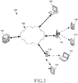
- FIGURE 1 illustrates an example computing system 100 according to this disclosure.
- the embodiment of the computing system 100 shown in FIGURE 1 is for illustration only. Other embodiments of the computing system 100 could be used without departing from the scope of this disclosure.
- the system 100 includes a network 102, which facilitates communication between various components in the system 100.
- the network 102 may communicate Internet Protocol (IP) packets, frame relay frames, Asynchronous Transfer Mode (ATM) cells, or other information between network addresses.
- IP Internet Protocol
- ATM Asynchronous Transfer Mode
- the network 102 may include one or more local area networks (LANs), metropolitan area networks (MANs), wide area networks (WANs), all or a portion of a global network such as the Internet, or any other communication system or systems at one or more locations.
- LANs local area networks
- MANs metropolitan area networks
- WANs wide area network
- the Internet or any other communication system or systems at one or more locations.
- the network 102 facilitates communications between at least one server 104 and various client devices 106-114.
- Each server 104 includes any suitable computing or processing device that can provide computing services for one or more client devices.
- Each server 104 could, for example, include one or more processing devices, one or more memories storing instructions and data, and one or more network interfaces facilitating communication over the network 102.
- Each client device 106-114 represents any suitable computing or processing device that interacts with at least one server or other computing device(s) over the network 102.
- the client devices 106-114 include a desktop computer 106, a mobile telephone or smartphone 108, a personal digital assistant (PDA) 110, a laptop computer 112, and a tablet computer 114.
- PDA personal digital assistant
- any other or additional client devices could be used in the computing system 100.
- client devices 108-114 communicate indirectly with the network 102.
- the client devices 108-110 communicate via one or more base stations 116, such as cellular base stations or eNodeBs.
- the client devices 112-114 communicate via one or more wireless access points 118, such as IEEE 802.11 wireless access points. Note that these are for illustration only and that each client device could communicate directly with the network 102 or indirectly with the network 102 via any suitable intermediate device(s) or network(s).
- FIGURE 1 illustrates one example of a computing system 100
- the system 100 could include any number of each component in any suitable arrangement.
- computing and communication systems come in a wide variety of configurations, and FIGURE 1 does not limit the scope of this disclosure to any particular configuration.
- FIGURE 1 illustrates one operational environment in which various features disclosed in this patent document can be used, these features could be used in any other suitable system.
- FIGURES 2 and 3 illustrate example devices in a computing system according to this disclosure.
- FIGURE 2 illustrates an example server 200
- FIGURE 3 illustrates an example client device 300 in a computing system according to this disclosure.
- the server 200 could represent the server 104 in FIGURE 1
- the client device 300 could represent one or more of the client devices 106-114 in FIGURE 1 .
- the server 200 includes a bus system 205, which supports communication between at least one processing device 210, at least one storage device 215, at least one communications unit 220, and at least one input/output (I/O) unit 225.
- a bus system 205 which supports communication between at least one processing device 210, at least one storage device 215, at least one communications unit 220, and at least one input/output (I/O) unit 225.
- the processing device 210 executes instructions that may be loaded into a memory 230.
- the processing device 210 may include any suitable number(s) and type(s) of processors or other devices in any suitable arrangement.
- Example types of processing devices 210 include microprocessors, microcontrollers, digital signal processors, field programmable gate arrays, application specific integrated circuits, and discreet circuitry.
- a The processing device 210 is configured to perform operations for unlocking an electronic device with an authenticated wearable device.
- the memory 230 and a persistent storage 235 are examples of storage devices 215, which represent any structure(s) capable of storing and facilitating retrieval of information (such as data, program code, and/or other suitable information on a temporary or permanent basis).
- the memory 230 may represent a random access memory or any other suitable volatile or non-volatile storage device(s).
- the persistent storage 235 may contain one or more components or devices supporting longer-term storage of data, such as a read only memory, hard drive, Flash memory, or optical disc.
- the communications unit 220 supports communications with other systems or devices.
- the communications unit 220 could include a network interface card or a wireless transceiver facilitating communications over the network 102.
- the communications unit 220 may support communications through any suitable physical or wireless communication link(s).
- the I/O unit 225 allows for input and output of data.
- the I/O unit 225 may provide a connection for user input through a keyboard, mouse, keypad, touchscreen, or other suitable input device.
- the I/O unit 225 may also send output to a display, printer, or other suitable output device.
- FIGURE 2 is described as representing the server 104 of FIGURE 1 , the same or similar structure could be used in one or more of the client devices 106-114.
- a laptop or desktop computer could have the same or similar structure as that shown in FIGURE 2 .
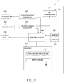
- the client device 300 includes an antenna 305, a radio frequency (RF) transceiver 310, transmit (TX) processing circuitry 315, a microphone 320, and receive (RX) processing circuitry 325.
- the client device 300 also includes a speaker 330, a main processor 340, an input/output (I/O) interface (IF) 345, a keypad 350, a display 355, and a memory 360.
- the memory 360 includes a basic operating system (OS) program 361 and one or more applications 362.
- OS basic operating system
- the RF transceiver 310 receives, from the antenna 305, an incoming RF signal transmitted by another component in a system.
- the RF transceiver 310 down-converts the incoming RF signal to generate an intermediate frequency (IF) or baseband signal.
- the IF or baseband signal is sent to the RX processing circuitry 325, which generates a processed baseband signal by filtering, decoding, and/or digitizing the baseband or IF signal.
- the RX processing circuitry 325 transmits the processed baseband signal to the speaker 330 (such as for voice data) or to the main processor 340 for further processing (such as for web browsing data).
- the TX processing circuitry 315 receives analog or digital voice data from the microphone 320 or other outgoing baseband data (such as web data, e-mail, or interactive video game data) from the main processor 340.
- the TX processing circuitry 315 encodes, multiplexes, and/or digitizes the outgoing baseband data to generate a processed baseband or IF signal.
- the RF transceiver 310 receives the outgoing processed baseband or IF signal from the TX processing circuitry 315 and up-converts the baseband or IF signal to an RF signal that is transmitted via the antenna 305.
- the main processor 340 can include one or more processors or other processing devices and execute the basic OS program 361 stored in the memory 360 in order to control the overall operation of the client device 300.
- the main processor 340 could control the reception of forward channel signals and the transmission of reverse channel signals by the RF transceiver 310, the RX processing circuitry 325, and the TX processing circuitry 315 in accordance with well-known principles.
- the main processor 340 includes at least one microprocessor or microcontroller.
- the main processor 340 is also capable of executing other processes and programs resident in the memory 360, such as operations for unlocking an electronic device with an authenticated wearable device.
- the main processor 340 can move data into or out of the memory 360 as required by an executing process.
- the main processor 340 is configured to execute the applications 362 based on the OS program 361 or in response to signals received from external devices or an operator.
- the main processor 340 is also coupled to the I/O interface 345, which provides the client device 300 with the ability to connect to other devices such as laptop computers and handheld computers.
- the I/O interface 345 is the communication path between these accessories and the main controller 340.
- the main processor 340 is also coupled to the keypad 350 and the display unit 355.
- the operator of the client device 300 can use the keypad 350 to enter data into the client device 300.
- the display 355 may be a liquid crystal display or other display capable of rendering text and/or at least limited graphics, such as from web sites.
- the memory 360 is coupled to the main processor 340.
- Part of the memory 360 could include a random access memory (RAM), and another part of the memory 360 could include a Flash memory or other read-only memory (ROM).
- RAM random access memory
- ROM read-only memory
- FIGURES 2 and 3 illustrate examples of devices in a computing system
- various changes may be made to FIGURES 2 and 3 .
- various components in FIGURES 2 and 3 could be combined, further subdivided, or omitted and additional components could be added according to particular needs.
- the main processor 340 could be divided into multiple processors, such as one or more central processing units (CPUs) and one or more graphics processing units (GPUs).
- FIGURE 3 illustrates the client device 300 configured as a mobile telephone or smartphone, client devices could be configured to operate as other types of mobile or stationary devices.
- client devices and servers can come in a wide variety of configurations, and FIGURES 2 and 3 do not limit this disclosure to any particular client device or server.
- FIGURE 4 is a flow diagram for registering a wearable device 405 with the electronic device 410 according to various embodiments of the disclosure. While the signal diagram depicts a series of sequential signals, unless explicitly stated, no inference should be drawn from that sequence regarding specific order of performance, performance of steps or portions thereof serially rather than concurrently or in an overlapping manner, or performance of the steps depicted exclusively without the occurrence of intervening or intermediate steps.
- the process depicted in the example depicted is implemented by processing circuitry in, for example, a wearable device and an electronic device.
- the user registers the wearable device 405 as a valid authenticator of the electronic device 410.
- the registration includes identifying the wearable device 405.
- the user establishing authentication settings on the electronic device 410 including, but not limited to, setting a password, setting a connection type, or setting a proximity for the authentication of the wearable device 405.
- the proximity may mean that a distance between the wearable device 405 and the electronic device 410 is equal to or less than threshold.
- the electronic device 410 transmits the validation data to the wearable device 405.
- the user validates the wearable device 425.
- the wearable device 405 displays the authentication information to the user for confirmation.
- the wearable device 405 requires the user to enter the password into an interface for validation.
- the wearable device 405 and the electronic device 410 exchange password data and key for the moving signature.
- the electronic device 410 notifies the wearable device 405 that the registration is complete. Once the registration is complete, the wearable device 405 is linked to the electronic device 410.
- FIGURES 5A-5C illustrate using a wearable device 505 to unlock a portable electronic device 510 according to various embodiments of the disclosure.
- the embodiments shown in FIGURES 5A, 5B and 5C are for illustration only. Other embodiments could be used without departing from the scope of the present disclosure.
- the wearable device 505 detects a portable electronic device 510 is within proximity.
- the portable electronic device 510 also detects the wearable device 505 is within proximity 515.
- the proximity 515 of the devices is determined during registration and set based on the connection type.
- the wearable device 505 and the portable electronic device 510 detect a movement 520 from one or more sensors including, but not limited to, embedded acceleration sensors and gyroscopes.
- the movement is original and cannot be previously found in the memory of the portable electronic device 510 or the wearable device 505.
- the movement 520 of the wearable device 525 is translated into a moving pattern 525.
- the movement 520 of the portable electronic device 510 is also translated into a moving pattern 530.
- the moving patterns 525 and 530 encompass the translation and rotation of the wearable device 505 and the portable electronic device 510 over a period of time.
- the moving patterns are determined using an acceleration in an x-direction, a y-direction, and a z-direction using the acceleration sensor of the respective devices and are oriented using a gyroscope of the respective devices
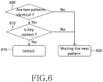
- FIGURE 6 illustrates a flow diagram for unlocking a portable electronic device 510 using a common pattern with a wearable device 505 according to various embodiments of the disclosure. While the flow chart depicts a series of steps, unless explicitly stated, no inference should be drawn from that sequence regarding specific order of performance, performance of steps or portions thereof serially rather than concurrently or in an overlapping manner, or performance of the steps depicted exclusively without the occurrence of intervening or intermediate steps.
- the process depicted in the example depicted is implemented by processing circuitry in, for example, an electronic device.
- the portable electronic device 510 determines whether the moving patterns 525 and 530 are identical.
- the portable electronic device 510 compares the translation and rotation against the time of the moving patterns 525 and 530 to determine whether they were created using the same movement 520. With translation movements, the moving patterns experience the same changes based on the user holding the phone.
- the portable electronic device 510 measures the rotation over time because the change in distance is different depending on the distance of the wearable device 505 and portable electronic device 510 from the point of rotation.
- the portable electronic device 510 determines whether the authentication key is correct. When the moving patterns are identical and the authentication key is verified, the portable electronic device 510 unlocks in operation 615. When either the moving patterns are determined to not be identical or the authentication key is not verified, the portable electronic device 510 remains locked and waits for the next pattern entered in operation 620.
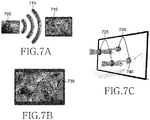
- FIGURES 7A-7C illustrate using a wearable device to unlock an electronic device according to various embodiments of the disclosure.
- the embodiments shown in FIGURES 7A-7C are for illustration only. Other embodiments could be used without departing from the scope of the present disclosure.
- the wearable device 705 detects an electronic device 710 is within proximity.
- the electronic device 710 also detects the wearable device 705 is within proximity 715.
- the proximity 715 of the devices is determined during registration and set based on the connection type.
- the wearable device 705 detects a movement 720 from one or more sensors including, but not limited to, embedded acceleration sensors and gyroscopes.
- the electronic device 710 receives an input 740 on a touchscreen 735 corresponding to the movement 720.
- the movement is original and cannot be previously found in the memory of the electronic device 710 or the wearable device 705.
- the movement 720 of the wearable device 725 is translated into a moving pattern 725.
- the movement 720 on the touchscreen 735 of the electronic device 710 is also translated into a moving pattern 730.
- the moving patterns 725 and 730 encompass the translation of the wearable device 705 and input 740 from the user over a period of time.
- the moving pattern of the wearable device 705 is determined using acceleration in an x-direction, a y-direction, and a z-direction using the acceleration sensor of the respective devices and are oriented using a gyroscope of the respective devices.
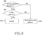
- FIGURE 8 illustrates a flow diagram for unlocking an electronic device 710 using a common pattern with a wearable device 705 according to various embodiments of the disclosure. While the flow chart depicts a series of steps, unless explicitly stated, no inference should be drawn from that sequence regarding specific order of performance, performance of steps or portions thereof serially rather than concurrently or in an overlapping manner, or performance of the steps depicted exclusively without the occurrence of intervening or intermediate steps.
- the process depicted in the example depicted is implemented by processing circuitry in, for example, an electronic device.
- the electronic device 710 determines whether the moving patterns 725 and 730 are identical.
- the electronic device 710 compares the translation and rotation against the time of the moving patterns 725 and 730 to determine whether they were created using the same movement 720.
- the electronic device 710 determines whether the authentication key is correct. When the moving patterns are identical and the authentication key is verified, the electronic device 710 unlocks in operation 815. When either the moving patterns are determined to not be identical or the authentication key is not verified, the electronic device 710 remains locked and waits for the next pattern entered in operation 820.
- FIGURE 9 is a method for unlocking an electronic device using a wearable device according to various embodiments of the disclosure. While the flow chart depicts a series of steps, unless explicitly stated, no inference should be drawn from that sequence regarding specific order of performance, performance of steps or portions thereof serially rather than concurrently or in an overlapping manner, or performance of the steps depicted exclusively without the occurrence of intervening or intermediate steps.
- the process depicted in the example depicted is implemented by processing circuitry in, for example, an electronic device.
- a wearable device 405 and an electronic device 410 wirelessly connect.
- the wireless connection can be made through any means known, for example, using BLUETOOTH or any near field communication (NFC).
- the wireless connection includes authenticating the wearable device 405, described above in context of FIGURE 4 .
- the password when the user removes the wearable device 405, the password is required to be entered when putting it back on to authenticate the user of the wearable device 405.
- the password can be a combination of letters and symbols using a keyboard, a PIN code, a special design, or any other form of inputting a password to verify a user.
- the wearable device 405 uses the sensors to determine when the wearable device 405 is removed.
- a movement is detected on the touchscreen of the electronic device 410.
- a movement is detected from the wearable device 405.
- the movement detected in the wearable device 405 and the password are encrypted and sent to the electronic device 410.
- the electronic device 410 compares the moving pattern on the touchscreen to the moving pattern of the wearable device 410. In operation 925, the electronic device 410 unlocks when the moving patterns match.
- FIGURE 10 is a method for unlocking an electronic device using a wearable device according to various embodiments of the disclosure. While the flow chart depicts a series of steps, unless explicitly stated, no inference should be drawn from that sequence regarding specific order of performance, performance of steps or portions thereof serially rather than concurrently or in an overlapping manner, or performance of the steps depicted exclusively without the occurrence of intervening or intermediate steps.
- the process depicted in the example depicted is implemented by processing circuitry in, for example, an electronic system.
- a wearable device 405 and an electronic device 410 wirelessly connect.
- the wireless connection can be made through any means known, for example, using BLUETOOTH or near field communication (NFC).
- the wireless connection includes authenticating the wearable device 405, described above in context of FIGURE 4 .
- the password when the user removes the wearable device 405, the password is required to be entered when putting it back on to authenticate the user of the wearable device 405.
- the password can be a combination of letters and symbols using a keyboard, a PIN code, a special design, or any other form of inputting a password to verify a user.
- the wearable device 405 uses the sensors to determine when the wearable device 405 is removed.
- a movement is detected from the electronic device 410.
- a movement is detected from the wearable device 405.
- the movement detected in the wearable device 405 and the password are encrypted and sent to the electronic device 410.
- the electronic device 410 compares the moving pattern on the touchscreen to the moving pattern of the wearable device 410. In operation 1025, the electronic device 410 unlocks when the moving patterns match.
- FIGURE 11 is a flow chart for unlocking an electronic device using a wearable device according to various embodiments of the disclosure. While the flow chart depicts a series of steps, unless explicitly stated, no inference should be drawn from that sequence regarding specific order of performance, performance of steps or portions thereof serially rather than concurrently or in an overlapping manner, or performance of the steps depicted exclusively without the occurrence of intervening or intermediate steps.
- the process depicted in the example depicted is implemented by processing circuitry in, for example, an electronic system.
- the electronic device receives information regarding a first movement of a wearable device from the wearable device.
- the electronic device receives information regarding the first movement of the wearable device with an encrypted password from the wearable device.
- receives information comprising an orientation measured by the wearable device using a gyroscope of the wearable device, an acceleration in an x-direction, an acceleration in a y-direction, and an acceleration in a z-direction measured by the wearable device using an accelerometer of the wearable device from the wearable device.
- the electronic device receives information regarding the first movement determined by the wearable device based on the accelerations and the orientation of the wearable device.
- the user authentication for the wearable device is a pin code.
- the electronic device detects a second movement.
- the electronic device detects a second movement comprising one of a movement on a display of a electronic device and a movement of the electronic device.
- the second movement is not saved.
- the electronic device measures an orientation using a gyroscope of the electronic device.
- the electronic device measures an acceleration in an x-direction, an acceleration in a y-direction, and an acceleration in a z-direction using an accelerometer of the electronic device.
- the electronic device determines the second movement based on the accelerations and the orientation of the electronic device.
- the electronic device unlocks the electronic device.
- the electronic device unlocks the electronic device if the first movement matches the second movement.
- the electronic device detects a proximity of the wearable device to the electronic device.
- the electronic device remains in a locked state while the electronic device is not with the proximity of the wearable device.
- the wearable device is registered as a valid authenticator for the electronic device.
Landscapes
- Engineering & Computer Science (AREA)
- Theoretical Computer Science (AREA)
- Computer Security & Cryptography (AREA)
- General Engineering & Computer Science (AREA)
- General Physics & Mathematics (AREA)
- Physics & Mathematics (AREA)
- Computer Hardware Design (AREA)
- Signal Processing (AREA)
- Computer Networks & Wireless Communication (AREA)
- Human Computer Interaction (AREA)
- Software Systems (AREA)
- Computing Systems (AREA)
- Multimedia (AREA)
- User Interface Of Digital Computer (AREA)
- Telephone Function (AREA)
Description
- The present application relates generally to user authentication and, more specifically, to a method and apparatus for unlocking password protected device based on motion signature and proximity.
- The current password based unlocking methods requires inconvenient manual password input every time, which is vulnerable because strangers can steal your pattern or passcode while you draw the pattern or type in passcode. An automatic unlocking method to resolve this problem could greatly improve user experience.
- Additionally, Prevalence of wearable devices is increasing. Wearable devices include many features like proximity sensor, heart rate sensor, accelerometer, gyroscope, BLUETOOTH connectivity and so on. Using proximity sensor to automatically unlock a device is not secure enough since the device could be stolen and still be used near the user. It requires more complex combination of sensors to effectively unlock a device with security in mind in addition to convenience.
-
EP2882174 A2 discloses a technique for device unlocking by motion detection with a paired device, which includes generating, by a first device, a first signal indicating a first pattern of movement of the first device; receiving, by the first device, a second signal indicating a second pattern of movement of a second device that is paired to the first device in accordance with a wireless communication protocol; comparing the first pattern of movement of the first device to the second pattern of movement of the second device; and unlocking the first device based on the first pattern of movement of the first device matching the second pattern of movement of the second device. -
WO2014/153528 A2 discloses a system method and authorization device for biometric access control to digital devices. The authentication device is attached to an arm or wrist of authorized users, and includes an accelerometer, digital radio, a processor configured to provide identity information over the radio, and to transmit motion data. The motion data is received by the digital device and the identity transmitted is verified as an identity associated with an authorized user. Input at a touchscreen, touchpad, mouse, trackball, or keyboard of the digital device is detected, and correlated with the motion data. Access to the digital device is allowed if the detected input and the detected motion data correlate, and disallowed otherwise. Access to the digital device is terminated if the detected input and the detected motion data do not continue to correlate, indicating that the user of the digital device is no longer the same authorized user. The digital device may be a part of a larger system having multiple workstations, such as a medical records database system. - A first example of the present disclosure provides a method capable of authenticating a user. The method includes wirelessly connecting a wearable device and an electronic device. The method also includes detecting a movement on a touchscreen of the electronic device. The method also includes detecting a movement of the wearable device. The movement on the touchscreen and the movement of the wearable device are compared. The electronic device is unlocked when the movement on the touchscreen matches the movement of the wearable device.
- A second example of the present disclosure provides a method for authenticating a user. The method includes wirelessly connecting a wearable device and an electronic device. The method also includes detecting a movement of the electronic device. The method also includes detecting a movement of the wearable device. The method further includes comparing the movement of the electronic device and the movement of the wearable device. Additionally, the method also includes unlocking the electronic device when the movement of the electronic device matches the movement of the wearable device.
- A first embodiment provides a method for authenticating a user. The method includes receiving, by an electronic device, first moving pattern information of a wearable device from the wearable device, wherein the wearable device is registered as a valid authenticator for the electronic device; determining, by the electronic device, second moving pattern information of an input received on a display of the electronic device, wherein the second moving pattern information indicates a non-predetermined moving pattern of the input; and unlocking, by the electronic device, the electronic device if the first moving pattern information of the wearable device corresponds to the second moving pattern information of the input.
- Before undertaking the DETAILED DESCRIPTION below, it may be advantageous to set forth definitions of certain words and phrases used throughout this patent document. The term "couple" and its derivatives refer to any direct or indirect communication between two or more elements, whether or not those elements are in physical contact with one another. The terms "transmit," "receive," and "communicate," as well as derivatives thereof, encompass both direct and indirect communication. The terms "include" and "comprise," as well as derivatives thereof, mean inclusion without limitation. The term "or" is inclusive, meaning and/or. The phrase "associated with," as well as derivatives thereof, means to include, be included within, interconnect with, contain, be contained within, connect to or with, couple to or with, be communicable with, cooperate with, interleave, juxtapose, be proximate to, be bound to or with, have, have a property of, have a relationship to or with, or the like. The term "controller" means any device, system or part thereof that controls at least one operation. Such a controller may be implemented in hardware or a combination of hardware and software and/or firmware. The functionality associated with any particular controller may be centralized or distributed, whether locally or remotely. The phrase "at least one of," when used with a list of items, means that different combinations of one or more of the listed items may be used, and only one item in the list may be needed. For example, "at least one of: A, B, and C" includes any of the following combinations: A, B, C, A and B, A and C, B and C, and A and B and C.
- Definitions for other certain words and phrases are provided throughout this patent document. Those of ordinary skill in the art should understand that in many if not most instances, such definitions apply to prior as well as future uses of such defined words and phrases.
- For a more complete understanding of the present disclosure and its advantages, reference is now made to the following description taken in conjunction with the accompanying drawings, in which like reference numerals represent like parts:
-
FIGURE 1 illustrates an example computing system according to this disclosure; -
FIGURES 2 and3 illustrate example devices in a computing system according to this disclosure; -
FIGURE 4 is a flow diagram for registering a wearable device with the electronic device according to this disclosure; -
FIGURES 5A, 5B and 5C illustrate using a wearable device to unlock a portable electronic device according to this disclosure; -
FIGURE 6 illustrates a flow diagram for unlocking a portable electronic device using a common pattern with a wearable device according to this disclosure; -
FIGURES 7A, 7B and 7C illustrate using a wearable device to unlock an electronic device according to this disclosure; -
FIGURE 8 illustrates a flow diagram for unlocking an electronic device using a common pattern with a wearable device according to this disclosure; -
FIGURE 9 is a method for unlocking an electronic device using a wearable device according to this disclosure; -
FIGURE 10 is a method for unlocking an electronic device using a wearable device according to this disclosure; and -
FIGURE 11 is a flow chart for unlocking an electronic device using a wearable device according to various embodiments of the disclosure. -
FIGURES 1 through 11 , discussed below, and the various embodiments used to describe the principles of the present invention in this patent document are by way of illustration only and should not be construed in any way to limit the scope of the disclosure. Those skilled in the art will understand that the principles of this disclosure may be implemented in any suitably arranged device or system. - Embodiments of the present disclosure provide an unnoticed unlocking method using a wearable device. The wearable device can be used as a secure authenticator to identify a user using the natural hand moving pattern detected by wearable device and touch screen device to unlock. The hand moving pattern doesn't require saving on the wearable device or other device, but the system determines whether the two patterns are identical.
- For a small device such as a mobile phone, the moving signature pattern is checked between the hand movement and the mobile movement grabbed by the hand. For example, naturally lifting the phone from pocket for use. For a touch screen such as PC screen or TV, the moving signature pattern is checked between the hand movement and the trajectory of random lines the user draw on the screen.
- Because no specific hand motion ends are required, there is not a login authentication that can be detected by anybody. Embodiments of the present disclosure provide more convenient unlocking methods by simply lifting a phone, mobile phone, or tablet or drawing a random line on the touch screen of a PC monitor, TV, etc.
-
FIGURE 1 illustrates anexample computing system 100 according to this disclosure. The embodiment of thecomputing system 100 shown inFIGURE 1 is for illustration only. Other embodiments of thecomputing system 100 could be used without departing from the scope of this disclosure. - As shown in
FIGURE 1 , thesystem 100 includes anetwork 102, which facilitates communication between various components in thesystem 100. For example, thenetwork 102 may communicate Internet Protocol (IP) packets, frame relay frames, Asynchronous Transfer Mode (ATM) cells, or other information between network addresses. Thenetwork 102 may include one or more local area networks (LANs), metropolitan area networks (MANs), wide area networks (WANs), all or a portion of a global network such as the Internet, or any other communication system or systems at one or more locations. - The
network 102 facilitates communications between at least oneserver 104 and various client devices 106-114. Eachserver 104 includes any suitable computing or processing device that can provide computing services for one or more client devices. Eachserver 104 could, for example, include one or more processing devices, one or more memories storing instructions and data, and one or more network interfaces facilitating communication over thenetwork 102. - Each client device 106-114 represents any suitable computing or processing device that interacts with at least one server or other computing device(s) over the
network 102. In this example, the client devices 106-114 include adesktop computer 106, a mobile telephone orsmartphone 108, a personal digital assistant (PDA) 110, alaptop computer 112, and atablet computer 114. However, any other or additional client devices could be used in thecomputing system 100. - In this example, some client devices 108-114 communicate indirectly with the
network 102. For example, the client devices 108-110 communicate via one ormore base stations 116, such as cellular base stations or eNodeBs. Also, the client devices 112-114 communicate via one or morewireless access points 118, such as IEEE 802.11 wireless access points. Note that these are for illustration only and that each client device could communicate directly with thenetwork 102 or indirectly with thenetwork 102 via any suitable intermediate device(s) or network(s). - Although
FIGURE 1 illustrates one example of acomputing system 100, various changes may be made toFIGURE 1 . For example, thesystem 100 could include any number of each component in any suitable arrangement. In general, computing and communication systems come in a wide variety of configurations, andFIGURE 1 does not limit the scope of this disclosure to any particular configuration. WhileFIGURE 1 illustrates one operational environment in which various features disclosed in this patent document can be used, these features could be used in any other suitable system. -
FIGURES 2 and3 illustrate example devices in a computing system according to this disclosure. In particular,FIGURE 2 illustrates anexample server 200, andFIGURE 3 illustrates anexample client device 300 in a computing system according to this disclosure. Theserver 200 could represent theserver 104 inFIGURE 1 , and theclient device 300 could represent one or more of the client devices 106-114 inFIGURE 1 . - As shown in
FIGURE 2 , theserver 200 includes abus system 205, which supports communication between at least oneprocessing device 210, at least onestorage device 215, at least onecommunications unit 220, and at least one input/output (I/O)unit 225. - The
processing device 210 executes instructions that may be loaded into amemory 230. Theprocessing device 210 may include any suitable number(s) and type(s) of processors or other devices in any suitable arrangement. Example types ofprocessing devices 210 include microprocessors, microcontrollers, digital signal processors, field programmable gate arrays, application specific integrated circuits, and discreet circuitry. A Theprocessing device 210 is configured to perform operations for unlocking an electronic device with an authenticated wearable device. - The
memory 230 and apersistent storage 235 are examples ofstorage devices 215, which represent any structure(s) capable of storing and facilitating retrieval of information (such as data, program code, and/or other suitable information on a temporary or permanent basis). Thememory 230 may represent a random access memory or any other suitable volatile or non-volatile storage device(s). Thepersistent storage 235 may contain one or more components or devices supporting longer-term storage of data, such as a read only memory, hard drive, Flash memory, or optical disc. - The
communications unit 220 supports communications with other systems or devices. For example, thecommunications unit 220 could include a network interface card or a wireless transceiver facilitating communications over thenetwork 102. Thecommunications unit 220 may support communications through any suitable physical or wireless communication link(s). - The I/
O unit 225 allows for input and output of data. For example, the I/O unit 225 may provide a connection for user input through a keyboard, mouse, keypad, touchscreen, or other suitable input device. The I/O unit 225 may also send output to a display, printer, or other suitable output device. - Note that while
FIGURE 2 is described as representing theserver 104 ofFIGURE 1 , the same or similar structure could be used in one or more of the client devices 106-114. For example, a laptop or desktop computer could have the same or similar structure as that shown inFIGURE 2 . - As shown in
FIGURE 3 , theclient device 300 includes anantenna 305, a radio frequency (RF)transceiver 310, transmit (TX)processing circuitry 315, amicrophone 320, and receive (RX)processing circuitry 325. Theclient device 300 also includes aspeaker 330, amain processor 340, an input/output (I/O) interface (IF) 345, akeypad 350, adisplay 355, and amemory 360. Thememory 360 includes a basic operating system (OS)program 361 and one ormore applications 362. - The
RF transceiver 310 receives, from theantenna 305, an incoming RF signal transmitted by another component in a system. TheRF transceiver 310 down-converts the incoming RF signal to generate an intermediate frequency (IF) or baseband signal. The IF or baseband signal is sent to theRX processing circuitry 325, which generates a processed baseband signal by filtering, decoding, and/or digitizing the baseband or IF signal. TheRX processing circuitry 325 transmits the processed baseband signal to the speaker 330 (such as for voice data) or to themain processor 340 for further processing (such as for web browsing data). - The
TX processing circuitry 315 receives analog or digital voice data from themicrophone 320 or other outgoing baseband data (such as web data, e-mail, or interactive video game data) from themain processor 340. TheTX processing circuitry 315 encodes, multiplexes, and/or digitizes the outgoing baseband data to generate a processed baseband or IF signal. TheRF transceiver 310 receives the outgoing processed baseband or IF signal from theTX processing circuitry 315 and up-converts the baseband or IF signal to an RF signal that is transmitted via theantenna 305. - The
main processor 340 can include one or more processors or other processing devices and execute thebasic OS program 361 stored in thememory 360 in order to control the overall operation of theclient device 300. For example, themain processor 340 could control the reception of forward channel signals and the transmission of reverse channel signals by theRF transceiver 310, theRX processing circuitry 325, and theTX processing circuitry 315 in accordance with well-known principles. In some embodiments, themain processor 340 includes at least one microprocessor or microcontroller. - The
main processor 340 is also capable of executing other processes and programs resident in thememory 360, such as operations for unlocking an electronic device with an authenticated wearable device. Themain processor 340 can move data into or out of thememory 360 as required by an executing process. In some embodiments, themain processor 340 is configured to execute theapplications 362 based on theOS program 361 or in response to signals received from external devices or an operator. Themain processor 340 is also coupled to the I/O interface 345, which provides theclient device 300 with the ability to connect to other devices such as laptop computers and handheld computers. The I/O interface 345 is the communication path between these accessories and themain controller 340. - The
main processor 340 is also coupled to thekeypad 350 and thedisplay unit 355. The operator of theclient device 300 can use thekeypad 350 to enter data into theclient device 300. Thedisplay 355 may be a liquid crystal display or other display capable of rendering text and/or at least limited graphics, such as from web sites. - The
memory 360 is coupled to themain processor 340. Part of thememory 360 could include a random access memory (RAM), and another part of thememory 360 could include a Flash memory or other read-only memory (ROM). - Although
FIGURES 2 and3 illustrate examples of devices in a computing system, various changes may be made toFIGURES 2 and3 . For example, various components inFIGURES 2 and3 could be combined, further subdivided, or omitted and additional components could be added according to particular needs. As a particular example, themain processor 340 could be divided into multiple processors, such as one or more central processing units (CPUs) and one or more graphics processing units (GPUs). Also, whileFIGURE 3 illustrates theclient device 300 configured as a mobile telephone or smartphone, client devices could be configured to operate as other types of mobile or stationary devices. In addition, as with computing and communication networks, client devices and servers can come in a wide variety of configurations, andFIGURES 2 and3 do not limit this disclosure to any particular client device or server. -
FIGURE 4 is a flow diagram for registering awearable device 405 with theelectronic device 410 according to various embodiments of the disclosure. While the signal diagram depicts a series of sequential signals, unless explicitly stated, no inference should be drawn from that sequence regarding specific order of performance, performance of steps or portions thereof serially rather than concurrently or in an overlapping manner, or performance of the steps depicted exclusively without the occurrence of intervening or intermediate steps. The process depicted in the example depicted is implemented by processing circuitry in, for example, a wearable device and an electronic device. - In
operation 415, the user registers thewearable device 405 as a valid authenticator of theelectronic device 410. The registration includes identifying thewearable device 405. In certain embodiments, the user establishing authentication settings on theelectronic device 410 including, but not limited to, setting a password, setting a connection type, or setting a proximity for the authentication of thewearable device 405. The proximity may mean that a distance between thewearable device 405 and theelectronic device 410 is equal to or less than threshold. - In
operation 420, theelectronic device 410 transmits the validation data to thewearable device 405. In operation 425, the user validates the wearable device 425. Thewearable device 405 displays the authentication information to the user for confirmation. In certain embodiments, thewearable device 405 requires the user to enter the password into an interface for validation. - In
operation 430, thewearable device 405 and theelectronic device 410 exchange password data and key for the moving signature. Inoperation 435, theelectronic device 410 notifies thewearable device 405 that the registration is complete. Once the registration is complete, thewearable device 405 is linked to theelectronic device 410. -
FIGURES 5A-5C illustrate using awearable device 505 to unlock a portableelectronic device 510 according to various embodiments of the disclosure. The embodiments shown inFIGURES 5A, 5B and 5C are for illustration only. Other embodiments could be used without departing from the scope of the present disclosure. - In
FIGURE 5A , thewearable device 505 detects a portableelectronic device 510 is within proximity. The portableelectronic device 510 also detects thewearable device 505 is withinproximity 515. Theproximity 515 of the devices is determined during registration and set based on the connection type. - In
FIGURE 5B , once thewearable device 505 is determined to be within proximity of the portableelectronic device 510, thewearable device 505 and the portableelectronic device 510 detect amovement 520 from one or more sensors including, but not limited to, embedded acceleration sensors and gyroscopes. The movement is original and cannot be previously found in the memory of the portableelectronic device 510 or thewearable device 505. - In
FIGURE 5C , themovement 520 of thewearable device 525 is translated into a movingpattern 525. Themovement 520 of the portableelectronic device 510 is also translated into a movingpattern 530. The movingpatterns wearable device 505 and the portableelectronic device 510 over a period of time. The moving patterns are determined using an acceleration in an x-direction, a y-direction, and a z-direction using the acceleration sensor of the respective devices and are oriented using a gyroscope of the respective devices -
FIGURE 6 illustrates a flow diagram for unlocking a portableelectronic device 510 using a common pattern with awearable device 505 according to various embodiments of the disclosure. While the flow chart depicts a series of steps, unless explicitly stated, no inference should be drawn from that sequence regarding specific order of performance, performance of steps or portions thereof serially rather than concurrently or in an overlapping manner, or performance of the steps depicted exclusively without the occurrence of intervening or intermediate steps. The process depicted in the example depicted is implemented by processing circuitry in, for example, an electronic device. - In
operation 605, after receiving the moving pattern and the authentication information from thewearable device 505, the portableelectronic device 510 determines whether the movingpatterns electronic device 510 compares the translation and rotation against the time of the movingpatterns same movement 520. With translation movements, the moving patterns experience the same changes based on the user holding the phone. In certain embodiments, the portableelectronic device 510 measures the rotation over time because the change in distance is different depending on the distance of thewearable device 505 and portableelectronic device 510 from the point of rotation. - In
operation 610, once the portableelectronic device 510 determines the two patterns are identical, the portableelectronic device 510 determines whether the authentication key is correct. When the moving patterns are identical and the authentication key is verified, the portableelectronic device 510 unlocks inoperation 615. When either the moving patterns are determined to not be identical or the authentication key is not verified, the portableelectronic device 510 remains locked and waits for the next pattern entered inoperation 620. -
FIGURES 7A-7C illustrate using a wearable device to unlock an electronic device according to various embodiments of the disclosure. The embodiments shown inFIGURES 7A-7C are for illustration only. Other embodiments could be used without departing from the scope of the present disclosure. - In
FIGURE 7A , thewearable device 705 detects anelectronic device 710 is within proximity. Theelectronic device 710 also detects thewearable device 705 is withinproximity 715. Theproximity 715 of the devices is determined during registration and set based on the connection type. - In
FIGURE 7B , once thewearable device 705 is determined to be within proximity of theelectronic device 710, thewearable device 705 detects amovement 720 from one or more sensors including, but not limited to, embedded acceleration sensors and gyroscopes. Theelectronic device 710 receives aninput 740 on atouchscreen 735 corresponding to themovement 720. The movement is original and cannot be previously found in the memory of theelectronic device 710 or thewearable device 705. - In
FIGURE 7C , themovement 720 of thewearable device 725 is translated into a movingpattern 725. Themovement 720 on thetouchscreen 735 of theelectronic device 710 is also translated into a movingpattern 730. The movingpatterns wearable device 705 andinput 740 from the user over a period of time. The moving pattern of thewearable device 705 is determined using acceleration in an x-direction, a y-direction, and a z-direction using the acceleration sensor of the respective devices and are oriented using a gyroscope of the respective devices. -
FIGURE 8 illustrates a flow diagram for unlocking anelectronic device 710 using a common pattern with awearable device 705 according to various embodiments of the disclosure. While the flow chart depicts a series of steps, unless explicitly stated, no inference should be drawn from that sequence regarding specific order of performance, performance of steps or portions thereof serially rather than concurrently or in an overlapping manner, or performance of the steps depicted exclusively without the occurrence of intervening or intermediate steps. The process depicted in the example depicted is implemented by processing circuitry in, for example, an electronic device. - In
operation 805, after receiving the moving pattern and the authentication information from thewearable device 705, theelectronic device 710 determines whether the movingpatterns electronic device 710 compares the translation and rotation against the time of the movingpatterns same movement 720. - In
operation 810, once theelectronic device 710 determines the two patterns are identical, theelectronic device 710 determines whether the authentication key is correct. When the moving patterns are identical and the authentication key is verified, theelectronic device 710 unlocks inoperation 815. When either the moving patterns are determined to not be identical or the authentication key is not verified, theelectronic device 710 remains locked and waits for the next pattern entered inoperation 820. -
FIGURE 9 is a method for unlocking an electronic device using a wearable device according to various embodiments of the disclosure. While the flow chart depicts a series of steps, unless explicitly stated, no inference should be drawn from that sequence regarding specific order of performance, performance of steps or portions thereof serially rather than concurrently or in an overlapping manner, or performance of the steps depicted exclusively without the occurrence of intervening or intermediate steps. The process depicted in the example depicted is implemented by processing circuitry in, for example, an electronic device. - In
operation 905, awearable device 405 and anelectronic device 410 wirelessly connect. The wireless connection can be made through any means known, for example, using BLUETOOTH or any near field communication (NFC). The wireless connection includes authenticating thewearable device 405, described above in context ofFIGURE 4 . - In certain embodiments, when the user removes the
wearable device 405, the password is required to be entered when putting it back on to authenticate the user of thewearable device 405. The password can be a combination of letters and symbols using a keyboard, a PIN code, a special design, or any other form of inputting a password to verify a user. Thewearable device 405 uses the sensors to determine when thewearable device 405 is removed. - In
operation 910, a movement is detected on the touchscreen of theelectronic device 410. Inoperation 915, a movement is detected from thewearable device 405. The movement detected in thewearable device 405 and the password are encrypted and sent to theelectronic device 410. - In
operation 920, theelectronic device 410 compares the moving pattern on the touchscreen to the moving pattern of thewearable device 410. Inoperation 925, theelectronic device 410 unlocks when the moving patterns match. -
FIGURE 10 is a method for unlocking an electronic device using a wearable device according to various embodiments of the disclosure. While the flow chart depicts a series of steps, unless explicitly stated, no inference should be drawn from that sequence regarding specific order of performance, performance of steps or portions thereof serially rather than concurrently or in an overlapping manner, or performance of the steps depicted exclusively without the occurrence of intervening or intermediate steps. The process depicted in the example depicted is implemented by processing circuitry in, for example, an electronic system. - In
operation 1005, awearable device 405 and anelectronic device 410 wirelessly connect. The wireless connection can be made through any means known, for example, using BLUETOOTH or near field communication (NFC). The wireless connection includes authenticating thewearable device 405, described above in context ofFIGURE 4 . - In certain embodiments, when the user removes the
wearable device 405, the password is required to be entered when putting it back on to authenticate the user of thewearable device 405. The password can be a combination of letters and symbols using a keyboard, a PIN code, a special design, or any other form of inputting a password to verify a user. Thewearable device 405 uses the sensors to determine when thewearable device 405 is removed. - In
operation 1010, a movement is detected from theelectronic device 410. Inoperation 1015, a movement is detected from thewearable device 405. The movement detected in thewearable device 405 and the password are encrypted and sent to theelectronic device 410. - In
operation 1020, theelectronic device 410 compares the moving pattern on the touchscreen to the moving pattern of thewearable device 410. Inoperation 1025, theelectronic device 410 unlocks when the moving patterns match. -
FIGURE 11 is a flow chart for unlocking an electronic device using a wearable device according to various embodiments of the disclosure. While the flow chart depicts a series of steps, unless explicitly stated, no inference should be drawn from that sequence regarding specific order of performance, performance of steps or portions thereof serially rather than concurrently or in an overlapping manner, or performance of the steps depicted exclusively without the occurrence of intervening or intermediate steps. The process depicted in the example depicted is implemented by processing circuitry in, for example, an electronic system. - In
operation 1105, the electronic device receives information regarding a first movement of a wearable device from the wearable device. The electronic device receives information regarding the first movement of the wearable device with an encrypted password from the wearable device. The electronic device receives information comprising an orientation measured by the wearable device using a gyroscope of the wearable device, an acceleration in an x-direction, an acceleration in a y-direction, and an acceleration in a z-direction measured by the wearable device using an accelerometer of the wearable device from the wearable device. The electronic device receives information regarding the first movement determined by the wearable device based on the accelerations and the orientation of the wearable device. The electronic device receives information regarding a user authentication entered on the wearable device and validated for the user. The user authentication remains active on the wearable device until the wearable device is removed by the user. The user authentication for the wearable device is a pin code. - In
operation 1110, the electronic device detects a second movement. The electronic device detects a second movement comprising one of a movement on a display of a electronic device and a movement of the electronic device. The second movement is not saved. The electronic device measures an orientation using a gyroscope of the electronic device. The electronic device measures an acceleration in an x-direction, an acceleration in a y-direction, and an acceleration in a z-direction using an accelerometer of the electronic device. The electronic device determines the second movement based on the accelerations and the orientation of the electronic device. - In
operation 1115, the electronic device unlocks the electronic device. The electronic device unlocks the electronic device if the first movement matches the second movement. The electronic device detects a proximity of the wearable device to the electronic device. The electronic device remains in a locked state while the electronic device is not with the proximity of the wearable device. The wearable device is registered as a valid authenticator for the electronic device. - Although the present disclosure has been described with an exemplary embodiment, various changes and modifications may be suggested to one skilled in the art. It is intended that the present disclosure encompass such changes and modifications as fall within the scope of the appended claims.
Claims (12)
- A method for authenticating a user, the method comprising:receiving (1105), by an electronic device (410, 510, 710), first moving pattern information of a wearable device (405, 505, 705) from the wearable device (405, 505, 705), wherein the wearable device (405, 505, 705) is registered as a valid authenticator for the electronic device (410, 510, 710);determining, by the electronic device (410, 510, 710), second moving pattern information of an input received on a display of the electronic device (410, 510, 710), wherein the second moving pattern information indicates a non-predetermined moving pattern of the input; andunlocking (1115), by the electronic device (410, 510, 710), the electronic device (410, 510, 710) if the first moving pattern information of the wearable device (405, 505, 705) corresponds to the second moving pattern information of the input.
- The method of Claim 1, wherein the second moving pattern information of the input is not saved.
- The method of Claim 1, wherein receiving the first moving pattern information of the wearable device (405, 505, 705) comprises receiving the first moving pattern information of the wearable device (405, 505, 705) with an encrypted password from the wearable device (405, 505, 705).
- The method of Claim 1, further comprising:
receiving the input on the display of the electronic device (410, 510, 710). - The method of Claim 4, further comprising:
comparing the first moving pattern information of the wearable device (405, 505, 705) with the second moving pattern information of the input. - The method of Claim 1, wherein the first moving pattern information of the wearable device (405, 505, 705) comprises:
an orientation measured by the wearable device (405, 505, 705) using a gyroscope of the wearable device (405, 505, 705), an acceleration in an x-direction, an acceleration in a y-direction, and an acceleration in a z-direction measured by the wearable device (405, 505, 705) using an accelerometer of the wearable device (405, 505, 705). - The method of Claim 6, wherein receiving the first moving pattern information of the wearable device (405, 505, 705) comprises:
receiving, from the wearable device (405, 505, 705), the first moving pattern information of the wearable device (405, 505, 705) determined based on the accelerations and the orientation of the wearable device (405, 505, 705). - The method of Claim 1, further comprising receiving, from the wearable device (405, 505, 705), information regarding a user authentication entered on the wearable device (405, 505, 705) validated for the user.
- The method of Claim 8, wherein the user authentication remains active on the wearable device (405, 505, 705) until the wearable device (405, 505, 705) is removed by the user.
- The method of Claim 1, further comprising:detecting a proximity of the wearable device (405, 505, 705) to the electronic device (410, 510, 710); andremaining in a locked state while the electronic device (410, 510, 710) is not with the proximity of the wearable device (405, 505, 705).
- The method of Claim 8, wherein the user authentication for the wearable device (405, 505, 705) is a pin code.
- An apparatus comprising means for carrying out the method of any one of claims 1 to 11.
Applications Claiming Priority (1)
| Application Number | Priority Date | Filing Date | Title |
|---|---|---|---|
| US14/793,600 US9680840B2 (en) | 2015-07-07 | 2015-07-07 | Password protected device unlock based on motion signature and proximity |
Publications (2)
| Publication Number | Publication Date |
|---|---|
| EP3115918A1 EP3115918A1 (en) | 2017-01-11 |
| EP3115918B1 true EP3115918B1 (en) | 2019-03-06 |
Family
ID=56096922
Family Applications (1)
| Application Number | Title | Priority Date | Filing Date |
|---|---|---|---|
| EP16169678.6A Not-in-force EP3115918B1 (en) | 2015-07-07 | 2016-05-13 | Method and apparatus for unlocking password protected device based on motion signature and proximity |
Country Status (2)
| Country | Link |
|---|---|
| US (1) | US9680840B2 (en) |
| EP (1) | EP3115918B1 (en) |
Families Citing this family (8)
| Publication number | Priority date | Publication date | Assignee | Title |
|---|---|---|---|---|
| US9973621B2 (en) * | 2015-11-23 | 2018-05-15 | Google Llc | Cross-device security scheme for tethered devices |
| WO2017180688A1 (en) * | 2016-04-15 | 2017-10-19 | Spectrum Brands, Inc. | Wireless lockset with integrated angle of arrival (aoa) detection |
| CN107422838B (en) * | 2016-05-24 | 2022-04-01 | 富泰华工业(深圳)有限公司 | Wearable device, unlocking control system and unlocking control method |
| CN110415387A (en) | 2018-04-27 | 2019-11-05 | 开利公司 | Gesture entry control system comprising a mobile device disposed in a receptacle carried by a user |
| CN110415389B (en) | 2018-04-27 | 2024-02-23 | 开利公司 | Gesture access control system and method for predicting location of mobile device relative to user |
| CN110415390A (en) | 2018-04-27 | 2019-11-05 | 开利公司 | Gesture entry control system using device gestures performed by a user of a mobile device |
| CN110415386A (en) | 2018-04-27 | 2019-11-05 | 开利公司 | Modeling of preprogrammed scene data for gesture-based entry control systems |
| US11171951B2 (en) | 2018-06-07 | 2021-11-09 | Paypal, Inc. | Device interface output based on biometric input orientation and captured proximate data |
Family Cites Families (7)
| Publication number | Priority date | Publication date | Assignee | Title |
|---|---|---|---|---|
| JP5224381B2 (en) | 2009-03-12 | 2013-07-03 | Necカシオモバイルコミュニケーションズ株式会社 | Portable electronic device and program |
| US9832206B2 (en) | 2013-03-21 | 2017-11-28 | The Trustees Of Dartmouth College | System, method and authorization device for biometric access control to digital devices |
| KR102179812B1 (en) * | 2013-07-18 | 2020-11-17 | 엘지전자 주식회사 | Watch type mobile terminal |
| WO2015065494A1 (en) * | 2013-11-04 | 2015-05-07 | Bodhi Technology Ventures Llc | Detecting stowing or unstowing of a mobile device |
| KR102193274B1 (en) | 2013-12-05 | 2020-12-22 | 삼성전자 주식회사 | Unlock method and apparatus |
| US20160050308A1 (en) * | 2014-08-13 | 2016-02-18 | Chang Liu | Movement-based, user identity authenticated unlocking and locking triggers for smartphones and wearable mobile devices |
| CN104283876A (en) | 2014-09-29 | 2015-01-14 | 小米科技有限责任公司 | Operation authorization method and device |
-
2015
- 2015-07-07 US US14/793,600 patent/US9680840B2/en not_active Expired - Fee Related
-
2016
- 2016-05-13 EP EP16169678.6A patent/EP3115918B1/en not_active Not-in-force
Non-Patent Citations (1)
| Title |
|---|
| None * |
Also Published As
| Publication number | Publication date |
|---|---|
| US20170012994A1 (en) | 2017-01-12 |
| US9680840B2 (en) | 2017-06-13 |
| EP3115918A1 (en) | 2017-01-11 |
Similar Documents
| Publication | Publication Date | Title |
|---|---|---|
| US9680840B2 (en) | Password protected device unlock based on motion signature and proximity | |
| US11170082B2 (en) | Mobile communications device providing heuristic security authentication features and related methods | |
| US9955350B2 (en) | Motion-based authentication for a gesture-based device | |
| US8625847B2 (en) | Login method based on direction of gaze | |
| EP2836957B1 (en) | Location-based access control for portable electronic device | |
| TWI452478B (en) | Method and system to access a function on a system | |
| US20130007876A1 (en) | System and method of providing biometric quick launch | |
| EP2503479B1 (en) | Login method based on direction of gaze | |
| US9185100B1 (en) | Device pairing using a cryptographic commitment process involving measured motion values | |
| CN107483213B (en) | Security authentication method, related device and system | |
| US20180039817A1 (en) | Method to authenticate or identify a user based upon fingerprint scans | |
| EP2864922A1 (en) | Authenticating a user of a system via an authentication image mechanism | |
| CN107451450A (en) | Biometric discrimination method and Related product | |
| US9531709B2 (en) | Securely unlocking a device using a combination of hold placement and gesture | |
| EP2634719A2 (en) | System and method of providing biometric quick launch | |
| CN106447325A (en) | Processing method and device based on NFC (Near Filed Communication), and mobile terminal | |
| US20160103989A1 (en) | Device authentication | |
| CN113127820A (en) | Terminal locking and unlocking method, MDM client and readable storage medium | |
| CN109299593B (en) | Bracelet unlocking method, intelligent bracelet and readable storage medium | |
| CN106897639B (en) | Mobile terminal and security verification method and device thereof | |
| US12579243B2 (en) | Providing dynamic authentication and authorization an on electronic device | |
| CN104935549A (en) | Authentication method and device for network account | |
| JP5277988B2 (en) | Wireless mobile terminal device security setting method and wireless mobile terminal device |
Legal Events
| Date | Code | Title | Description |
|---|---|---|---|
| PUAI | Public reference made under article 153(3) epc to a published international application that has entered the european phase |
Free format text: ORIGINAL CODE: 0009012 |
|
| STAA | Information on the status of an ep patent application or granted ep patent |
Free format text: STATUS: THE APPLICATION HAS BEEN PUBLISHED |
|
| AK | Designated contracting states |
Kind code of ref document: A1 Designated state(s): AL AT BE BG CH CY CZ DE DK EE ES FI FR GB GR HR HU IE IS IT LI LT LU LV MC MK MT NL NO PL PT RO RS SE SI SK SM TR |
|
| AX | Request for extension of the european patent |
Extension state: BA ME |
|
| STAA | Information on the status of an ep patent application or granted ep patent |
Free format text: STATUS: REQUEST FOR EXAMINATION WAS MADE |
|
| 17P | Request for examination filed |
Effective date: 20170127 |
|
| RBV | Designated contracting states (corrected) |
Designated state(s): AL AT BE BG CH CY CZ DE DK EE ES FI FR GB GR HR HU IE IS IT LI LT LU LV MC MK MT NL NO PL PT RO RS SE SI SK SM TR |
|
| STAA | Information on the status of an ep patent application or granted ep patent |
Free format text: STATUS: EXAMINATION IS IN PROGRESS |
|
| 17Q | First examination report despatched |
Effective date: 20170703 |
|
| REG | Reference to a national code |
Ref country code: DE Ref legal event code: R079 Ref document number: 602016010577 Country of ref document: DE Free format text: PREVIOUS MAIN CLASS: G06F0021320000 Ipc: G06F0001160000 |
|
| RIC1 | Information provided on ipc code assigned before grant |
Ipc: G06F 21/32 20130101ALI20181011BHEP Ipc: G09G 5/12 20060101ALI20181011BHEP Ipc: G06F 3/0488 20130101ALI20181011BHEP Ipc: H04L 29/06 20060101ALI20181011BHEP Ipc: G06F 1/16 20060101AFI20181011BHEP Ipc: G06F 3/0346 20130101ALI20181011BHEP Ipc: G06F 21/36 20130101ALI20181011BHEP Ipc: H04W 12/06 20090101ALI20181011BHEP Ipc: G06F 3/01 20060101ALI20181011BHEP |
|
| GRAP | Despatch of communication of intention to grant a patent |
Free format text: ORIGINAL CODE: EPIDOSNIGR1 |
|
| STAA | Information on the status of an ep patent application or granted ep patent |
Free format text: STATUS: GRANT OF PATENT IS INTENDED |
|
| INTG | Intention to grant announced |
Effective date: 20181120 |
|
| GRAS | Grant fee paid |
Free format text: ORIGINAL CODE: EPIDOSNIGR3 |
|
| GRAA | (expected) grant |
Free format text: ORIGINAL CODE: 0009210 |
|
| STAA | Information on the status of an ep patent application or granted ep patent |
Free format text: STATUS: THE PATENT HAS BEEN GRANTED |
|
| AK | Designated contracting states |
Kind code of ref document: B1 Designated state(s): AL AT BE BG CH CY CZ DE DK EE ES FI FR GB GR HR HU IE IS IT LI LT LU LV MC MK MT NL NO PL PT RO RS SE SI SK SM TR |
|
| REG | Reference to a national code |
Ref country code: GB Ref legal event code: FG4D |
|
| REG | Reference to a national code |
Ref country code: CH Ref legal event code: EP Ref country code: AT Ref legal event code: REF Ref document number: 1105396 Country of ref document: AT Kind code of ref document: T Effective date: 20190315 |
|
| REG | Reference to a national code |
Ref country code: DE Ref legal event code: R096 Ref document number: 602016010577 Country of ref document: DE |
|
| REG | Reference to a national code |
Ref country code: IE Ref legal event code: FG4D |
|
| REG | Reference to a national code |
Ref country code: NL Ref legal event code: MP Effective date: 20190306 |
|
| REG | Reference to a national code |
Ref country code: LT Ref legal event code: MG4D |
|
| PG25 | Lapsed in a contracting state [announced via postgrant information from national office to epo] |
Ref country code: LT Free format text: LAPSE BECAUSE OF FAILURE TO SUBMIT A TRANSLATION OF THE DESCRIPTION OR TO PAY THE FEE WITHIN THE PRESCRIBED TIME-LIMIT Effective date: 20190306 Ref country code: FI Free format text: LAPSE BECAUSE OF FAILURE TO SUBMIT A TRANSLATION OF THE DESCRIPTION OR TO PAY THE FEE WITHIN THE PRESCRIBED TIME-LIMIT Effective date: 20190306 Ref country code: NO Free format text: LAPSE BECAUSE OF FAILURE TO SUBMIT A TRANSLATION OF THE DESCRIPTION OR TO PAY THE FEE WITHIN THE PRESCRIBED TIME-LIMIT Effective date: 20190606 Ref country code: SE Free format text: LAPSE BECAUSE OF FAILURE TO SUBMIT A TRANSLATION OF THE DESCRIPTION OR TO PAY THE FEE WITHIN THE PRESCRIBED TIME-LIMIT Effective date: 20190306 |
|
| PGFP | Annual fee paid to national office [announced via postgrant information from national office to epo] |
Ref country code: DE Payment date: 20190423 Year of fee payment: 4 |
|
| PG25 | Lapsed in a contracting state [announced via postgrant information from national office to epo] |
Ref country code: NL Free format text: LAPSE BECAUSE OF FAILURE TO SUBMIT A TRANSLATION OF THE DESCRIPTION OR TO PAY THE FEE WITHIN THE PRESCRIBED TIME-LIMIT Effective date: 20190306 Ref country code: RS Free format text: LAPSE BECAUSE OF FAILURE TO SUBMIT A TRANSLATION OF THE DESCRIPTION OR TO PAY THE FEE WITHIN THE PRESCRIBED TIME-LIMIT Effective date: 20190306 Ref country code: HR Free format text: LAPSE BECAUSE OF FAILURE TO SUBMIT A TRANSLATION OF THE DESCRIPTION OR TO PAY THE FEE WITHIN THE PRESCRIBED TIME-LIMIT Effective date: 20190306 Ref country code: BG Free format text: LAPSE BECAUSE OF FAILURE TO SUBMIT A TRANSLATION OF THE DESCRIPTION OR TO PAY THE FEE WITHIN THE PRESCRIBED TIME-LIMIT Effective date: 20190606 Ref country code: LV Free format text: LAPSE BECAUSE OF FAILURE TO SUBMIT A TRANSLATION OF THE DESCRIPTION OR TO PAY THE FEE WITHIN THE PRESCRIBED TIME-LIMIT Effective date: 20190306 Ref country code: GR Free format text: LAPSE BECAUSE OF FAILURE TO SUBMIT A TRANSLATION OF THE DESCRIPTION OR TO PAY THE FEE WITHIN THE PRESCRIBED TIME-LIMIT Effective date: 20190607 |
|
| REG | Reference to a national code |
Ref country code: AT Ref legal event code: MK05 Ref document number: 1105396 Country of ref document: AT Kind code of ref document: T Effective date: 20190306 |
|
| PG25 | Lapsed in a contracting state [announced via postgrant information from national office to epo] |
Ref country code: AL Free format text: LAPSE BECAUSE OF FAILURE TO SUBMIT A TRANSLATION OF THE DESCRIPTION OR TO PAY THE FEE WITHIN THE PRESCRIBED TIME-LIMIT Effective date: 20190306 Ref country code: ES Free format text: LAPSE BECAUSE OF FAILURE TO SUBMIT A TRANSLATION OF THE DESCRIPTION OR TO PAY THE FEE WITHIN THE PRESCRIBED TIME-LIMIT Effective date: 20190306 Ref country code: PT Free format text: LAPSE BECAUSE OF FAILURE TO SUBMIT A TRANSLATION OF THE DESCRIPTION OR TO PAY THE FEE WITHIN THE PRESCRIBED TIME-LIMIT Effective date: 20190706 Ref country code: EE Free format text: LAPSE BECAUSE OF FAILURE TO SUBMIT A TRANSLATION OF THE DESCRIPTION OR TO PAY THE FEE WITHIN THE PRESCRIBED TIME-LIMIT Effective date: 20190306 Ref country code: IT Free format text: LAPSE BECAUSE OF FAILURE TO SUBMIT A TRANSLATION OF THE DESCRIPTION OR TO PAY THE FEE WITHIN THE PRESCRIBED TIME-LIMIT Effective date: 20190306 Ref country code: SK Free format text: LAPSE BECAUSE OF FAILURE TO SUBMIT A TRANSLATION OF THE DESCRIPTION OR TO PAY THE FEE WITHIN THE PRESCRIBED TIME-LIMIT Effective date: 20190306 Ref country code: RO Free format text: LAPSE BECAUSE OF FAILURE TO SUBMIT A TRANSLATION OF THE DESCRIPTION OR TO PAY THE FEE WITHIN THE PRESCRIBED TIME-LIMIT Effective date: 20190306 Ref country code: CZ Free format text: LAPSE BECAUSE OF FAILURE TO SUBMIT A TRANSLATION OF THE DESCRIPTION OR TO PAY THE FEE WITHIN THE PRESCRIBED TIME-LIMIT Effective date: 20190306 |
|
| PG25 | Lapsed in a contracting state [announced via postgrant information from national office to epo] |
Ref country code: SM Free format text: LAPSE BECAUSE OF FAILURE TO SUBMIT A TRANSLATION OF THE DESCRIPTION OR TO PAY THE FEE WITHIN THE PRESCRIBED TIME-LIMIT Effective date: 20190306 Ref country code: PL Free format text: LAPSE BECAUSE OF FAILURE TO SUBMIT A TRANSLATION OF THE DESCRIPTION OR TO PAY THE FEE WITHIN THE PRESCRIBED TIME-LIMIT Effective date: 20190306 |
|
| REG | Reference to a national code |
Ref country code: DE Ref legal event code: R097 Ref document number: 602016010577 Country of ref document: DE |
|
| REG | Reference to a national code |
Ref country code: CH Ref legal event code: PL |
|
| PG25 | Lapsed in a contracting state [announced via postgrant information from national office to epo] |
Ref country code: IS Free format text: LAPSE BECAUSE OF FAILURE TO SUBMIT A TRANSLATION OF THE DESCRIPTION OR TO PAY THE FEE WITHIN THE PRESCRIBED TIME-LIMIT Effective date: 20190706 Ref country code: AT Free format text: LAPSE BECAUSE OF FAILURE TO SUBMIT A TRANSLATION OF THE DESCRIPTION OR TO PAY THE FEE WITHIN THE PRESCRIBED TIME-LIMIT Effective date: 20190306 |
|
| PLBE | No opposition filed within time limit |
Free format text: ORIGINAL CODE: 0009261 |
|
| STAA | Information on the status of an ep patent application or granted ep patent |
Free format text: STATUS: NO OPPOSITION FILED WITHIN TIME LIMIT |
|
| PG25 | Lapsed in a contracting state [announced via postgrant information from national office to epo] |
Ref country code: LI Free format text: LAPSE BECAUSE OF NON-PAYMENT OF DUE FEES Effective date: 20190531 Ref country code: DK Free format text: LAPSE BECAUSE OF FAILURE TO SUBMIT A TRANSLATION OF THE DESCRIPTION OR TO PAY THE FEE WITHIN THE PRESCRIBED TIME-LIMIT Effective date: 20190306 Ref country code: CH Free format text: LAPSE BECAUSE OF NON-PAYMENT OF DUE FEES Effective date: 20190531 Ref country code: MC Free format text: LAPSE BECAUSE OF FAILURE TO SUBMIT A TRANSLATION OF THE DESCRIPTION OR TO PAY THE FEE WITHIN THE PRESCRIBED TIME-LIMIT Effective date: 20190306 |
|
| REG | Reference to a national code |
Ref country code: BE Ref legal event code: MM Effective date: 20190531 |
|
| 26N | No opposition filed |
Effective date: 20191209 |
|
| PG25 | Lapsed in a contracting state [announced via postgrant information from national office to epo] |
Ref country code: SI Free format text: LAPSE BECAUSE OF FAILURE TO SUBMIT A TRANSLATION OF THE DESCRIPTION OR TO PAY THE FEE WITHIN THE PRESCRIBED TIME-LIMIT Effective date: 20190306 Ref country code: LU Free format text: LAPSE BECAUSE OF NON-PAYMENT OF DUE FEES Effective date: 20190513 |
|
| PG25 | Lapsed in a contracting state [announced via postgrant information from national office to epo] |
Ref country code: TR Free format text: LAPSE BECAUSE OF FAILURE TO SUBMIT A TRANSLATION OF THE DESCRIPTION OR TO PAY THE FEE WITHIN THE PRESCRIBED TIME-LIMIT Effective date: 20190306 |
|
| PG25 | Lapsed in a contracting state [announced via postgrant information from national office to epo] |
Ref country code: IE Free format text: LAPSE BECAUSE OF NON-PAYMENT OF DUE FEES Effective date: 20190513 |
|
| PG25 | Lapsed in a contracting state [announced via postgrant information from national office to epo] |
Ref country code: BE Free format text: LAPSE BECAUSE OF NON-PAYMENT OF DUE FEES Effective date: 20190531 |
|
| PG25 | Lapsed in a contracting state [announced via postgrant information from national office to epo] |
Ref country code: FR Free format text: LAPSE BECAUSE OF NON-PAYMENT OF DUE FEES Effective date: 20190531 |
|
| REG | Reference to a national code |
Ref country code: DE Ref legal event code: R119 Ref document number: 602016010577 Country of ref document: DE |
|
| GBPC | Gb: european patent ceased through non-payment of renewal fee |
Effective date: 20200513 |
|
| PG25 | Lapsed in a contracting state [announced via postgrant information from national office to epo] |
Ref country code: GB Free format text: LAPSE BECAUSE OF NON-PAYMENT OF DUE FEES Effective date: 20200513 |
|
| PG25 | Lapsed in a contracting state [announced via postgrant information from national office to epo] |
Ref country code: DE Free format text: LAPSE BECAUSE OF NON-PAYMENT OF DUE FEES Effective date: 20201201 Ref country code: CY Free format text: LAPSE BECAUSE OF FAILURE TO SUBMIT A TRANSLATION OF THE DESCRIPTION OR TO PAY THE FEE WITHIN THE PRESCRIBED TIME-LIMIT Effective date: 20190306 |
|
| PG25 | Lapsed in a contracting state [announced via postgrant information from national office to epo] |
Ref country code: HU Free format text: LAPSE BECAUSE OF FAILURE TO SUBMIT A TRANSLATION OF THE DESCRIPTION OR TO PAY THE FEE WITHIN THE PRESCRIBED TIME-LIMIT; INVALID AB INITIO Effective date: 20160513 Ref country code: MT Free format text: LAPSE BECAUSE OF FAILURE TO SUBMIT A TRANSLATION OF THE DESCRIPTION OR TO PAY THE FEE WITHIN THE PRESCRIBED TIME-LIMIT Effective date: 20190306 |
|
| PG25 | Lapsed in a contracting state [announced via postgrant information from national office to epo] |
Ref country code: MK Free format text: LAPSE BECAUSE OF FAILURE TO SUBMIT A TRANSLATION OF THE DESCRIPTION OR TO PAY THE FEE WITHIN THE PRESCRIBED TIME-LIMIT Effective date: 20190306 |