EP3115739A1 - Warhead fragmenting structure of compacted fragments - Google Patents
Warhead fragmenting structure of compacted fragments Download PDFInfo
- Publication number
- EP3115739A1 EP3115739A1 EP16178738.7A EP16178738A EP3115739A1 EP 3115739 A1 EP3115739 A1 EP 3115739A1 EP 16178738 A EP16178738 A EP 16178738A EP 3115739 A1 EP3115739 A1 EP 3115739A1
- Authority
- EP
- European Patent Office
- Prior art keywords
- fragments
- fragmenting
- explosive device
- explosive
- metal
- Prior art date
- Legal status (The legal status is an assumption and is not a legal conclusion. Google has not performed a legal analysis and makes no representation as to the accuracy of the status listed.)
- Withdrawn
Links
- 239000012634 fragment Substances 0.000 title claims abstract description 151
- 239000002360 explosive Substances 0.000 claims abstract description 40
- 229910052751 metal Inorganic materials 0.000 claims abstract description 20
- 239000002184 metal Substances 0.000 claims abstract description 20
- 238000000034 method Methods 0.000 claims abstract description 19
- 238000004519 manufacturing process Methods 0.000 claims abstract description 11
- 239000000853 adhesive Substances 0.000 claims abstract description 10
- 230000001070 adhesive effect Effects 0.000 claims abstract description 10
- 239000007769 metal material Substances 0.000 claims abstract description 6
- 239000011248 coating agent Substances 0.000 claims abstract description 3
- 238000000576 coating method Methods 0.000 claims abstract description 3
- 238000010348 incorporation Methods 0.000 claims abstract description 3
- XEEYBQQBJWHFJM-UHFFFAOYSA-N Iron Chemical compound [Fe] XEEYBQQBJWHFJM-UHFFFAOYSA-N 0.000 claims description 6
- RYGMFSIKBFXOCR-UHFFFAOYSA-N Copper Chemical compound [Cu] RYGMFSIKBFXOCR-UHFFFAOYSA-N 0.000 claims description 3
- 229910001209 Low-carbon steel Inorganic materials 0.000 claims description 3
- 229910052802 copper Inorganic materials 0.000 claims description 3
- 239000010949 copper Substances 0.000 claims description 3
- 229910052742 iron Inorganic materials 0.000 claims description 3
- 229910052715 tantalum Inorganic materials 0.000 claims description 3
- GUVRBAGPIYLISA-UHFFFAOYSA-N tantalum atom Chemical compound [Ta] GUVRBAGPIYLISA-UHFFFAOYSA-N 0.000 claims description 3
- 230000001939 inductive effect Effects 0.000 claims 1
- 230000006835 compression Effects 0.000 description 15
- 238000007906 compression Methods 0.000 description 15
- 239000011800 void material Substances 0.000 description 8
- 239000007789 gas Substances 0.000 description 6
- 238000012856 packing Methods 0.000 description 6
- 229910000831 Steel Inorganic materials 0.000 description 4
- 238000013459 approach Methods 0.000 description 4
- 239000011159 matrix material Substances 0.000 description 4
- 239000010959 steel Substances 0.000 description 4
- POIUWJQBRNEFGX-XAMSXPGMSA-N cathelicidin Chemical compound C([C@@H](C(=O)N[C@@H](CCCNC(N)=N)C(=O)N[C@@H](CCCCN)C(=O)N[C@@H](CO)C(=O)N[C@@H](CCCCN)C(=O)N[C@@H](CCC(O)=O)C(=O)N[C@@H](CCCCN)C(=O)N[C@@H]([C@@H](C)CC)C(=O)NCC(=O)N[C@@H](CCCCN)C(=O)N[C@@H](CCC(O)=O)C(=O)N[C@@H](CC=1C=CC=CC=1)C(=O)N[C@@H](CCCCN)C(=O)N[C@@H](CCCNC(N)=N)C(=O)N[C@@H]([C@@H](C)CC)C(=O)N[C@@H](C(C)C)C(=O)N[C@@H](CCC(N)=O)C(=O)N[C@@H](CCCNC(N)=N)C(=O)N[C@@H]([C@@H](C)CC)C(=O)N[C@@H](CCCCN)C(=O)N[C@@H](CC(O)=O)C(=O)N[C@@H](CC=1C=CC=CC=1)C(=O)N[C@@H](CC(C)C)C(=O)N[C@@H](CCCNC(N)=N)C(=O)N[C@@H](CC(N)=O)C(=O)N[C@@H](CC(C)C)C(=O)N[C@@H](C(C)C)C(=O)N1[C@@H](CCC1)C(=O)N[C@@H](CCCNC(N)=N)C(=O)N[C@@H]([C@@H](C)O)C(=O)N[C@@H](CCC(O)=O)C(=O)N[C@@H](CO)C(O)=O)NC(=O)[C@H](CC=1C=CC=CC=1)NC(=O)[C@H](CC(O)=O)NC(=O)CNC(=O)[C@H](CC(C)C)NC(=O)[C@@H](N)CC(C)C)C1=CC=CC=C1 POIUWJQBRNEFGX-XAMSXPGMSA-N 0.000 description 3
- 238000005474 detonation Methods 0.000 description 3
- 239000000463 material Substances 0.000 description 3
- 239000004814 polyurethane Substances 0.000 description 3
- 229920002635 polyurethane Polymers 0.000 description 3
- 238000003825 pressing Methods 0.000 description 3
- 238000005056 compaction Methods 0.000 description 2
- 238000010586 diagram Methods 0.000 description 2
- 238000009826 distribution Methods 0.000 description 2
- 238000012545 processing Methods 0.000 description 2
- 239000007787 solid Substances 0.000 description 2
- 238000012546 transfer Methods 0.000 description 2
- 230000004913 activation Effects 0.000 description 1
- 238000010276 construction Methods 0.000 description 1
- 238000013461 design Methods 0.000 description 1
- 238000011038 discontinuous diafiltration by volume reduction Methods 0.000 description 1
- 230000000694 effects Effects 0.000 description 1
- 238000005530 etching Methods 0.000 description 1
- 238000004880 explosion Methods 0.000 description 1
- 238000013467 fragmentation Methods 0.000 description 1
- 238000006062 fragmentation reaction Methods 0.000 description 1
- 239000000203 mixture Substances 0.000 description 1
- 238000004806 packaging method and process Methods 0.000 description 1
- 230000003071 parasitic effect Effects 0.000 description 1
- 238000004904 shortening Methods 0.000 description 1
- 238000001228 spectrum Methods 0.000 description 1
- 239000007858 starting material Substances 0.000 description 1
Images


Classifications
-
- F—MECHANICAL ENGINEERING; LIGHTING; HEATING; WEAPONS; BLASTING
- F42—AMMUNITION; BLASTING
- F42B—EXPLOSIVE CHARGES, e.g. FOR BLASTING, FIREWORKS, AMMUNITION
- F42B12/00—Projectiles, missiles or mines characterised by the warhead, the intended effect, or the material
- F42B12/02—Projectiles, missiles or mines characterised by the warhead, the intended effect, or the material characterised by the warhead or the intended effect
- F42B12/20—Projectiles, missiles or mines characterised by the warhead, the intended effect, or the material characterised by the warhead or the intended effect of high-explosive type
- F42B12/22—Projectiles, missiles or mines characterised by the warhead, the intended effect, or the material characterised by the warhead or the intended effect of high-explosive type with fragmentation-hull construction
- F42B12/32—Projectiles, missiles or mines characterised by the warhead, the intended effect, or the material characterised by the warhead or the intended effect of high-explosive type with fragmentation-hull construction the hull or case comprising a plurality of discrete bodies, e.g. steel balls, embedded therein or disposed around the explosive charge
-
- F—MECHANICAL ENGINEERING; LIGHTING; HEATING; WEAPONS; BLASTING
- F42—AMMUNITION; BLASTING
- F42B—EXPLOSIVE CHARGES, e.g. FOR BLASTING, FIREWORKS, AMMUNITION
- F42B12/00—Projectiles, missiles or mines characterised by the warhead, the intended effect, or the material
- F42B12/02—Projectiles, missiles or mines characterised by the warhead, the intended effect, or the material characterised by the warhead or the intended effect
- F42B12/20—Projectiles, missiles or mines characterised by the warhead, the intended effect, or the material characterised by the warhead or the intended effect of high-explosive type
- F42B12/22—Projectiles, missiles or mines characterised by the warhead, the intended effect, or the material characterised by the warhead or the intended effect of high-explosive type with fragmentation-hull construction
- F42B12/24—Projectiles, missiles or mines characterised by the warhead, the intended effect, or the material characterised by the warhead or the intended effect of high-explosive type with fragmentation-hull construction with grooves, recesses or other wall weakenings
-
- F—MECHANICAL ENGINEERING; LIGHTING; HEATING; WEAPONS; BLASTING
- F42—AMMUNITION; BLASTING
- F42B—EXPLOSIVE CHARGES, e.g. FOR BLASTING, FIREWORKS, AMMUNITION
- F42B33/00—Manufacture of ammunition; Dismantling of ammunition; Apparatus therefor
-
- B—PERFORMING OPERATIONS; TRANSPORTING
- B21—MECHANICAL METAL-WORKING WITHOUT ESSENTIALLY REMOVING MATERIAL; PUNCHING METAL
- B21K—MAKING FORGED OR PRESSED METAL PRODUCTS, e.g. HORSE-SHOES, RIVETS, BOLTS OR WHEELS
- B21K21/00—Making hollow articles not covered by a single preceding sub-group
- B21K21/06—Shaping thick-walled hollow articles, e.g. projectiles
-
- B—PERFORMING OPERATIONS; TRANSPORTING
- B32—LAYERED PRODUCTS
- B32B—LAYERED PRODUCTS, i.e. PRODUCTS BUILT-UP OF STRATA OF FLAT OR NON-FLAT, e.g. CELLULAR OR HONEYCOMB, FORM
- B32B15/00—Layered products comprising a layer of metal
- B32B15/04—Layered products comprising a layer of metal comprising metal as the main or only constituent of a layer, which is next to another layer of the same or of a different material
- B32B15/043—Layered products comprising a layer of metal comprising metal as the main or only constituent of a layer, which is next to another layer of the same or of a different material of metal
-
- B—PERFORMING OPERATIONS; TRANSPORTING
- B32—LAYERED PRODUCTS
- B32B—LAYERED PRODUCTS, i.e. PRODUCTS BUILT-UP OF STRATA OF FLAT OR NON-FLAT, e.g. CELLULAR OR HONEYCOMB, FORM
- B32B9/00—Layered products comprising a layer of a particular substance not covered by groups B32B11/00 - B32B29/00
- B32B9/04—Layered products comprising a layer of a particular substance not covered by groups B32B11/00 - B32B29/00 comprising such particular substance as the main or only constituent of a layer, which is next to another layer of the same or of a different material
- B32B9/041—Layered products comprising a layer of a particular substance not covered by groups B32B11/00 - B32B29/00 comprising such particular substance as the main or only constituent of a layer, which is next to another layer of the same or of a different material of metal
-
- Y—GENERAL TAGGING OF NEW TECHNOLOGICAL DEVELOPMENTS; GENERAL TAGGING OF CROSS-SECTIONAL TECHNOLOGIES SPANNING OVER SEVERAL SECTIONS OF THE IPC; TECHNICAL SUBJECTS COVERED BY FORMER USPC CROSS-REFERENCE ART COLLECTIONS [XRACs] AND DIGESTS
- Y10—TECHNICAL SUBJECTS COVERED BY FORMER USPC
- Y10T—TECHNICAL SUBJECTS COVERED BY FORMER US CLASSIFICATION
- Y10T428/00—Stock material or miscellaneous articles
- Y10T428/12—All metal or with adjacent metals
- Y10T428/12014—All metal or with adjacent metals having metal particles
- Y10T428/12028—Composite; i.e., plural, adjacent, spatially distinct metal components [e.g., layers, etc.]
- Y10T428/12063—Nonparticulate metal component
- Y10T428/1209—Plural particulate metal components
Definitions
- the invention is related to the field of exploding ordnance including warheads.
- a typical warhead may have a casing formed of a unitary, integral body, e.g., a steel cone or cylinder) that naturally fractures into fragments upon detonation of an explosive charge of the warhead.
- a naturally fragmenting open parenthesis (e.g., steel cased) warhead produces a spectrum of fragment sizes depending on the steel properties and the associated fracture statistics (e.g., so-called Mott distribution).
- Other warheads may have a casing or liner formed as an assemblage of fragments rather than as a unitary body.
- Such pre-formed fragment warheads may be made with fragments having desired individual fragment shapes and masses. In some cases the fragments may all have the same shape and mass, while in other cases it may be desired to include multiple different sizes and masses for desired effects.
- packing densities for randomly-placed fragments in a large convex volume are on the order of 0.64 for ball-shaped fragments, and 0.78 for cube-shaped fragments. While packing densities can be increased using a more ordered placement process in manufacturing (e.g., hand placement), such processing increases cost. Random packing is desirable for low cost manufacture. As an example, a collection of fragments may simply be dumped into an enveloping structure, which is a generally low cost process.
- a warhead uses several hundred (e.g., 900) pre-formed 0.9 gm steel ball fragments held together in a polyurethane matrix.
- the packing density is likely well less than 1.0, e.g., in the range of 0.5 - 0.74, and the polyurethane-filled voids provide escape channels for gases generated at detonation, so that less energy is transferred to the fragments than would be in the absence of such escape channels. Fragment velocity is thus less than it might be, limiting the effectiveness of the warhead accordingly.
- the average fragment velocity for a unitary-body warhead might be approximately 1500 meters per second, while the average fragment velocity for such a steel-ball warhead might be approximately 1200 meters per second, 20% lower.
- warhead design is to use unitary structures that have been etched in some manner to form fragments that are still joined together by a remaining non-etched part of the structure.
- a cylindrical structure may be formed by a stack of rings having their outer surfaces deeply etched to define such fragmenting portions.
- pre-formed fragmenting warhead that has higher effectiveness than current pre-formed fragmenting warheads, e.g., higher fragment velocity due to absence of escape channels, while also being simple and low-cost to manufacture.
- pre-formed metal fragments are random-packaged and then compacted together to remove void space.
- the fragments are made of a ductile metal that deforms under the applied pressure, causing the fragments to better conform to each other and reduce/remove void space. This can provide packing density approaching 100%, and thus higher fragment launch velocity due to the absence of gaps between fragments.
- the fragments are preferably bonded to each other so that a resulting structure is rigid and strong for subsequent handling (e.g., incorporating into warhead assembly). Bonding may be provided by coating the fragments with thin adhesive before compaction.
- L/D is ratio of maximum fragment diameter/minimum fragment diameter.
- L/D is very close to 1, and an ordnance definition of a compact fragment is L/D ⁇ 1.5.
- compacting is preferably done in a way that achieves desired L/D ⁇ 1.0 of the compressed fragments, beginning with the randomly packed fragments.
- a method of making a fragmenting structure for an explosive device.
- the method includes placing a volume of fragments of a deformable metal material into a press mold, the fragments having sufficient surface adhesiveness to adhere to each other upon being compressed together.
- the method further includes compressing the fragments together in the press mold to form the fragmenting structure as a rigid and substantially void-free structure of compression-deformed, mutually adhering metal fragments, the fragmenting structure being sized and shaped for subsequent incorporation into the explosive device.
- an explosive device in another aspect, includes an explosive charge and a fragmenting structure adjacent to the explosive charge, the fragmenting structure being a rigid and substantially void-free structure of compression-deformed, mutually adhering metal fragments.
- the structure may have been manufactured by the disclosed method, for example.
- pre-formed fragment warheads have the advantage of being able to launch a number of metallic fragments having desired individual fragment masses.
- Existing pre-formed fragment warheads have some drawbacks compared to naturally fragmenting warheads having the same size, mass and charge-to-mass ratio.
- Launch velocity for the pre-formed fragment warhead is less on average than for the naturally-fragmenting warhead because of explosive gas blow-by.
- Some of the mass launched by the pre-formed fragment warhead is parasitic, because matrix material (e.g., polyurethane) is used to encapsulate the pre-formed fragments. Therefore less actual metallic fragment mass is produced by the pre-formed fragment warhead and the fragments have lower launch velocity for the same mass warhead.
- An advanced fragmenting warhead uses pre-formed metal fragments and a void reduction technique to produce mass-efficient fragment packaging which achieves higher launch velocity by reducing explosive gas blow-by during explosive launch. Individual fragment mass is controlled, so that all fragments can have the same mass if so designed. A larger number of higher velocity fragments can be produced from the same mass warhead compared to a standard pre-formed warhead. Alternatively, the same number, mass and velocity fragments can be produced by a lighter-weight warhead. The technique may also achieve desired low production cost of the fragmenting warhead liners.
- the approach to remove much of the void volume between the pre-formed fragments is by compressing an appropriate number of fragments together under high pressure, e.g., using a punch and die set.
- the compression causes the fragments to deform so as to better conform to each other, reducing voids.
- the pre-formed fragments may be coated with a thin layer of adhesive, then the coated fragments are poured into a lubricated die.
- the punch at the appropriate load (tonnage or PSI) then compacts the assemblage of fragments into a final shape which conforms to the shape of the die. After curing of the adhesive the warhead liner is removed from the die set.
- annular punch and die set can be used to form a hollow cylindrical structure which serves as the external housing for a central, cylindrical explosive charge.
- Other warhead liner shapes are possible as well.
- the fragments Upon explosive detonation, the fragments will be launched at high velocity and will separate from one another.
- the fragments will have the same mass as before compaction and be quite compact, but they may have a variety of shapes depending upon their locations in the die during compression.
- fragments are “compressed” in the sense of “experiencing a compressive force.”
- the fragments are generally of metal and thus incompressible in the sense of experiencing volume reduction. Being of a ductile/malleable material, however, the fragments do react to compressive forces by deforming in shape, such as explained herein.
- the disclosed warhead liner fabrication approach may perform better than the standard pre-formed fragment warhead.
- the removal of the void space also removes the "escape channels" or open paths by which the explosive gases can escape between the fragments, providing more impulse to the fragments during explosive launch. No significant matrix material is required and no matrix material is launched along with the fragments as happens in a standard pre-formed fragment warhead. With the void volume removed the compacted pre-formed fragments have higher velocity than in the standard pre-formed warhead approach, and more fragments can be incorporated into the same fragmenting liner volume.
- Figure 1 shows a cylindrical explosive device or "warhead” 10 in axial cross section.
- Major components include a cylindrical fragmenting structure 12 surrounding explosive fill 14, with a detonator 16 at one end and a V-shaped cap 18 at the other end.
- the V-shaped cap 18 and explosive fill 14 define a shaped charge.
- the V-shaped cap 18 may be replaced with an element having flatter structure forming an end plate or an explosively formed penetrator (EFP).
- EFP explosively formed penetrator
- Figure 2 illustrates the fragmenting structure 12. It is composed of metal fragments 20 whose shapes result from high-pressure compression as described below.
- the fragmenting structure 12 may be disposed between thin inner and outer liners 22, 24.
- the fragments 20 are preferably of a ductile/malleable metal, including for example tantalum, copper, iron and mild steel. Under sufficient compression, the fragments 20 deform into essentially random polyhedral shapes, conforming to each other and filling any voids that might exist prior to compression. As an example, the fragments 20 may initially all have spherical shapes, creating corresponding voids in a packed collection. Under sufficient compression, the fragments 20 deform to substantially remove the voids.
- the fragments 20 may be coated with an adhesive prior to compression, so that upon curing they adhere to each other and form a substantially solid structure.
- the warhead 10 of Figure 1 is detonated by activation of the detonator 16 in conventional fashion.
- Pressure from explosion of the explosive fill 14 causes the fragmenting structure 12 to break apart.
- the fragmenting structure 12 naturally breaks apart into the fragments 20, i.e., separated from each other and being thrust radially outwardly away from the axis of the warhead 12.
- the fragments 20 are of controlled size(s) which can be tailored to inflict desired damage on targets, potentially more effective than other types of fragmenting structures such as unitary casings/liners etc.
- fragmenting structure 12 because of the essentially void-free characteristic of the fragmenting structure 12, there is efficient transfer of kinetic energy from the explosive gases to the fragments 20, imparting a higher average velocity/energy than alternative structures that contain inter-fragment voids (e.g., in structures of packed spherical balls for example) that permit escape of explosive gases and thus reduce average energy transfer.
- inter-fragment voids e.g., in structures of packed spherical balls for example
- Figure 3 illustrates compression-induced deformation of spherical balls 30 of ductile/malleable metal material.
- the balls 30 are compressed together along the line separating their centers, resulting in a flattening of both balls 30 where they meet.
- Such compression creates point to point contact initially, but as deformation progresses the balls flatten against each other in the original plane perpendicular to the axis through their centers and containing the initial point of contact.
- Figure 4 illustrates an individual fragment 20. As shown, it has a generally polyhedral solid shape, with flattened surface areas where it has been compressed against adjacent fragments 20.
- a fragment 20 may start out having any of a variety of shapes, such as spherical, cubic, etc. As explained above, upon compression the fragments deform into respective final shapes that may resemble that of Figure 4 .
- One aspect of fragment shape is the so-called "L/D ratio", which is the ratio of the maximum fragment diameter/minimum fragment diameter. For ordnance it is generally desired that L/D be less than about 1.5.
- the chunky fragment 20 of Figure 4 may be within this limit. It may be the case that starting with cubic pre-formed fragments rather than spherical would produce desirably chunkier deformed fragments 20, because less volumetric void space needs to be removed so less average deformation is required.
- the fragmenting structure 12 will generally be made using a press mold and pressing operation.
- the fragments 20 in their initial shapes are poured or otherwise placed into the mold, then sufficiently high pressure is applied to compress the collection of fragments 20 into the final, relatively void-free fragmenting structure 12.
- One specific example of such a technique is described below. Those skilled in the art will appreciate that the structure 12 can be made using other techniques.
- compressing fragments axially in a die results in shortening their axial dimension, which can undesirably increase L/D if the original fragments have a spherical or similar compact shape.
- a technique is described below that may be used to produce fragments with an L/D ⁇ 1.
- a converging die and an annular punch are used.
- the fragments are forced into a reduced-radius cylinder, e.g., having a radius about 20% less than the radius of an upper part of the die.
- This compression into a reduced-radius cylinder causes radial or "hoop" compression of the fragments. Because the fragment material is essentially incompressible, the hoop compression causes an axial lengthening of the fragments, restoring L/D ⁇ 1.
- Figures 5 - 8 illustrate a method of making a fragmenting structure 12 using a punch 40 and die 42. This example uses spherical metal balls 44 as starting material for the fragments 20.
- Figure 5 shows an axial cross-sectional view
- Figure 6 shows a top view of the die 42 alone.
- the die 42 has a cylindrical channel 46 formed therein, with a converging section 48 leading between an upper section of a given radius and a lower section having a lower radius.
- the balls 44 are placed in the upper section and the punch 40 is pressed downwardly to compress the balls 44 together.
- Figure 7 shows an intermediate condition in which the balls 44' have been deformed under the compression to generally rectangular shapes, i.e., having axial-direction lengths less than their radial-direction lengths/widths.
- the L/D ratios of the compressed balls 44' may be greater than desired.
- Figure 8 shows a later condition in which some of the compressed balls, indicated at 44", have been forced in to the converging section 48. Being forced to the smaller-radius region, the incompressible balls 44" experience a hoop stress that further deforms them, in this case causing them to lengthen slightly in the axial direction, thus tending to reduce L/D to a value closer to 1.
- the arrangement of Figures 5-8 can produce the fragmenting structure 12 with fragments 20 having acceptable L/D ratios for use in a fragmenting warhead.
- Figure 9 is a high-level flow diagram of the method of making the fragmenting structure 12.
- the starting fragments are coated with an adhesive to promote mutual bonding for creating a unitary structure, as described above.
- the starting fragments may have any of a variety of shapes, such as spherical, cubic, etc. They may be of uniform size or there may be a desired mixture or distribution of multiple sizes.
- the coated fragments are placed into a press mold, preferably packed together to minimize the initial void space.
- the collection of fragments is pressed in the press mold.
- This pressing should be of sufficient magnitude and duration to bring about the desired deformation of the fragments that substantially removes the voids, as described above.
- the required pressure may be about 4 times the ultimate strength of the fragment material.
- the compression may be on the order of 200,000 PSI or higher.
- the resulting structure is removed from the mold, and the adhesive allowed to cure.
- the result is a rigid and mechanically robust fragmenting structure, such as the structure 12 described above.
- This structure is then incorporated into the warhead assembly to produce the final warhead or explosive device.
- mixed-size fragments might be incorporated into a single pressing operation, i.e., first mixed together then pressed to make the liner.
Landscapes
- Engineering & Computer Science (AREA)
- General Engineering & Computer Science (AREA)
- Chemical & Material Sciences (AREA)
- Combustion & Propulsion (AREA)
- Manufacturing & Machinery (AREA)
- Pressure Welding/Diffusion-Bonding (AREA)
Abstract
A method of making a fragmenting structure for an explosive device includes placing a volume of fragments of a deformable metal material into a press mold, the fragments having sufficient surface adhesiveness to adhere to each other upon being compressed together, e.g., by coating the fragments with adhesive. The fragments are compressed together in the press mold to form the fragmenting structure as a rigid and substantially void-free structure of compression-deformed, mutually adhering metal fragments, the fragmenting structure being sized and shaped for subsequent incorporation into the explosive device. An explosive device includes an explosive charge and a fragmenting structure adjacent to the explosive charge, the fragmenting structure being a rigid and substantially void-free structure of compression-deformed, mutually adhering metal fragments. The structure may have been manufactured by the disclosed method.
Description
- The invention is related to the field of exploding ordnance including warheads.
- A typical warhead may have a casing formed of a unitary, integral body, e.g., a steel cone or cylinder) that naturally fractures into fragments upon detonation of an explosive charge of the warhead. A naturally fragmenting open parenthesis (e.g., steel cased) warhead produces a spectrum of fragment sizes depending on the steel properties and the associated fracture statistics (e.g., so-called Mott distribution).
- Other warheads may have a casing or liner formed as an assemblage of fragments rather than as a unitary body. Such pre-formed fragment warheads may be made with fragments having desired individual fragment shapes and masses. In some cases the fragments may all have the same shape and mass, while in other cases it may be desired to include multiple different sizes and masses for desired effects.
- One challenge with pre-formed fragment warheads is to achieve desirably high packing density of the fragments. Generally, packing densities for randomly-placed fragments in a large convex volume are on the order of 0.64 for ball-shaped fragments, and 0.78 for cube-shaped fragments. While packing densities can be increased using a more ordered placement process in manufacturing (e.g., hand placement), such processing increases cost. Random packing is desirable for low cost manufacture. As an example, a collection of fragments may simply be dumped into an enveloping structure, which is a generally low cost process.
- In one example, a warhead uses several hundred (e.g., 900) pre-formed 0.9 gm steel ball fragments held together in a polyurethane matrix. The packing density is likely well less than 1.0, e.g., in the range of 0.5 - 0.74, and the polyurethane-filled voids provide escape channels for gases generated at detonation, so that less energy is transferred to the fragments than would be in the absence of such escape channels. Fragment velocity is thus less than it might be, limiting the effectiveness of the warhead accordingly. As a further example, the average fragment velocity for a unitary-body warhead might be approximately 1500 meters per second, while the average fragment velocity for such a steel-ball warhead might be approximately 1200 meters per second, 20% lower.
- Another approach to warhead design is to use unitary structures that have been etched in some manner to form fragments that are still joined together by a remaining non-etched part of the structure. In one example, a cylindrical structure may be formed by a stack of rings having their outer surfaces deeply etched to define such fragmenting portions. These warheads may provide better performance due to the absence of escape channels, but the etching and related processing causes the manufacturing costs to be high.
- It would be desirable to have a pre-formed fragmenting warhead that has higher effectiveness than current pre-formed fragmenting warheads, e.g., higher fragment velocity due to absence of escape channels, while also being simple and low-cost to manufacture.
- In a disclosed technique, pre-formed metal fragments are random-packaged and then compacted together to remove void space. The fragments are made of a ductile metal that deforms under the applied pressure, causing the fragments to better conform to each other and reduce/remove void space. This can provide packing density approaching 100%, and thus higher fragment launch velocity due to the absence of gaps between fragments.
- The fragments are preferably bonded to each other so that a resulting structure is rigid and strong for subsequent handling (e.g., incorporating into warhead assembly). Bonding may be provided by coating the fragments with thin adhesive before compaction.
- Another aspect is to manage so-called "L/D", which is ratio of maximum fragment diameter/minimum fragment diameter. Ideally L/D is very close to 1, and an ordnance definition of a compact fragment is L/D < 1.5. Thus, compacting is preferably done in a way that achieves desired L/D∼1.0 of the compressed fragments, beginning with the randomly packed fragments.
- In one aspect, a method is disclosed of making a fragmenting structure for an explosive device. The method includes placing a volume of fragments of a deformable metal material into a press mold, the fragments having sufficient surface adhesiveness to adhere to each other upon being compressed together. The method further includes compressing the fragments together in the press mold to form the fragmenting structure as a rigid and substantially void-free structure of compression-deformed, mutually adhering metal fragments, the fragmenting structure being sized and shaped for subsequent incorporation into the explosive device.
- In another aspect, an explosive device is disclosed that includes an explosive charge and a fragmenting structure adjacent to the explosive charge, the fragmenting structure being a rigid and substantially void-free structure of compression-deformed, mutually adhering metal fragments. The structure may have been manufactured by the disclosed method, for example.
- The foregoing and other objects, features and advantages will be apparent from the following description of particular embodiments of the invention, as illustrated in the accompanying drawings in which like reference characters refer to the same parts throughout the different views.
-
Figure 1 is a schematic sectional view of a cylindrical explosive device, also referred to as a warhead; -
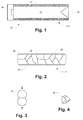
Figure 2 is a close-up schematic view of a section of a fragmenting structure; -
Figure 3 is a schematic depiction of compressive deformation of spherical fragments; -
Figure 4 is a perspective view of a compressively deformed fragment; -
Figures 5 - 8 show a punch and die press mold and its use in making a cylindrical fragmenting structure; and -
Figure 9 is a flow diagram of a method of making a fragmenting structure for a warhead. - Briefly recapping, pre-formed fragment warheads have the advantage of being able to launch a number of metallic fragments having desired individual fragment masses. Existing pre-formed fragment warheads have some drawbacks compared to naturally fragmenting warheads having the same size, mass and charge-to-mass ratio. Launch velocity for the pre-formed fragment warhead is less on average than for the naturally-fragmenting warhead because of explosive gas blow-by. Some of the mass launched by the pre-formed fragment warhead is parasitic, because matrix material (e.g., polyurethane) is used to encapsulate the pre-formed fragments. Therefore less actual metallic fragment mass is produced by the pre-formed fragment warhead and the fragments have lower launch velocity for the same mass warhead.
- An advanced fragmenting warhead is disclosed that uses pre-formed metal fragments and a void reduction technique to produce mass-efficient fragment packaging which achieves higher launch velocity by reducing explosive gas blow-by during explosive launch. Individual fragment mass is controlled, so that all fragments can have the same mass if so designed. A larger number of higher velocity fragments can be produced from the same mass warhead compared to a standard pre-formed warhead. Alternatively, the same number, mass and velocity fragments can be produced by a lighter-weight warhead. The technique may also achieve desired low production cost of the fragmenting warhead liners.
- The approach to remove much of the void volume between the pre-formed fragments is by compressing an appropriate number of fragments together under high pressure, e.g., using a punch and die set. The compression causes the fragments to deform so as to better conform to each other, reducing voids. The pre-formed fragments may be coated with a thin layer of adhesive, then the coated fragments are poured into a lubricated die. The punch at the appropriate load (tonnage or PSI) then compacts the assemblage of fragments into a final shape which conforms to the shape of the die. After curing of the adhesive the warhead liner is removed from the die set. For example an annular punch and die set can be used to form a hollow cylindrical structure which serves as the external housing for a central, cylindrical explosive charge. Other warhead liner shapes are possible as well. Upon explosive detonation, the fragments will be launched at high velocity and will separate from one another. The fragments will have the same mass as before compaction and be quite compact, but they may have a variety of shapes depending upon their locations in the die during compression.
- It should be understood that the individual fragments are "compressed" in the sense of "experiencing a compressive force." The fragments are generally of metal and thus incompressible in the sense of experiencing volume reduction. Being of a ductile/malleable material, however, the fragments do react to compressive forces by deforming in shape, such as explained herein.
- The disclosed warhead liner fabrication approach may perform better than the standard pre-formed fragment warhead. The removal of the void space, for example, also removes the "escape channels" or open paths by which the explosive gases can escape between the fragments, providing more impulse to the fragments during explosive launch. No significant matrix material is required and no matrix material is launched along with the fragments as happens in a standard pre-formed fragment warhead. With the void volume removed the compacted pre-formed fragments have higher velocity than in the standard pre-formed warhead approach, and more fragments can be incorporated into the same fragmenting liner volume.
-
Figure 1 shows a cylindrical explosive device or "warhead" 10 in axial cross section. Major components include acylindrical fragmenting structure 12 surroundingexplosive fill 14, with adetonator 16 at one end and a V-shapedcap 18 at the other end. In this configuration the V-shapedcap 18 andexplosive fill 14 define a shaped charge. In alternative embodiments the V-shapedcap 18 may be replaced with an element having flatter structure forming an end plate or an explosively formed penetrator (EFP). -
Figure 2 illustrates the fragmentingstructure 12. It is composed ofmetal fragments 20 whose shapes result from high-pressure compression as described below. The fragmentingstructure 12 may be disposed between thin inner andouter liners fragments 20 are preferably of a ductile/malleable metal, including for example tantalum, copper, iron and mild steel. Under sufficient compression, thefragments 20 deform into essentially random polyhedral shapes, conforming to each other and filling any voids that might exist prior to compression. As an example, thefragments 20 may initially all have spherical shapes, creating corresponding voids in a packed collection. Under sufficient compression, thefragments 20 deform to substantially remove the voids. Thefragments 20 may be coated with an adhesive prior to compression, so that upon curing they adhere to each other and form a substantially solid structure. - In operation, the
warhead 10 ofFigure 1 is detonated by activation of thedetonator 16 in conventional fashion. Pressure from explosion of theexplosive fill 14 causes the fragmentingstructure 12 to break apart. Given the pre-fragmentation of this structure, i.e., its construction fromfragments 20 with relatively weak surface bonding therebetween, the fragmentingstructure 12 naturally breaks apart into thefragments 20, i.e., separated from each other and being thrust radially outwardly away from the axis of thewarhead 12. Thefragments 20 are of controlled size(s) which can be tailored to inflict desired damage on targets, potentially more effective than other types of fragmenting structures such as unitary casings/liners etc. Also, because of the essentially void-free characteristic of the fragmentingstructure 12, there is efficient transfer of kinetic energy from the explosive gases to thefragments 20, imparting a higher average velocity/energy than alternative structures that contain inter-fragment voids (e.g., in structures of packed spherical balls for example) that permit escape of explosive gases and thus reduce average energy transfer. -
Figure 3 illustrates compression-induced deformation ofspherical balls 30 of ductile/malleable metal material. In this simplified example theballs 30 are compressed together along the line separating their centers, resulting in a flattening of bothballs 30 where they meet. Such compression creates point to point contact initially, but as deformation progresses the balls flatten against each other in the original plane perpendicular to the axis through their centers and containing the initial point of contact. -
Figure 4 illustrates anindividual fragment 20. As shown, it has a generally polyhedral solid shape, with flattened surface areas where it has been compressed againstadjacent fragments 20. Generally, afragment 20 may start out having any of a variety of shapes, such as spherical, cubic, etc. As explained above, upon compression the fragments deform into respective final shapes that may resemble that ofFigure 4 . One aspect of fragment shape is the so-called "L/D ratio", which is the ratio of the maximum fragment diameter/minimum fragment diameter. For ordnance it is generally desired that L/D be less than about 1.5. Thechunky fragment 20 ofFigure 4 may be within this limit. It may be the case that starting with cubic pre-formed fragments rather than spherical would produce desirably chunkierdeformed fragments 20, because less volumetric void space needs to be removed so less average deformation is required. - Returning to
Figure 2 , the fragmentingstructure 12 will generally be made using a press mold and pressing operation. Thefragments 20 in their initial shapes are poured or otherwise placed into the mold, then sufficiently high pressure is applied to compress the collection offragments 20 into the final, relatively void-free fragmenting structure 12. One specific example of such a technique is described below. Those skilled in the art will appreciate that thestructure 12 can be made using other techniques. - As noted above, compressing fragments axially in a die results in shortening their axial dimension, which can undesirably increase L/D if the original fragments have a spherical or similar compact shape. A technique is described below that may be used to produce fragments with an L/D ∼ 1. In this example, a converging die and an annular punch are used. The fragments are forced into a reduced-radius cylinder, e.g., having a radius about 20% less than the radius of an upper part of the die. This compression into a reduced-radius cylinder causes radial or "hoop" compression of the fragments. Because the fragment material is essentially incompressible, the hoop compression causes an axial lengthening of the fragments, restoring L/D ∼ 1.
-
Figures 5 - 8 illustrate a method of making a fragmentingstructure 12 using apunch 40 and die 42. This example usesspherical metal balls 44 as starting material for thefragments 20. -
Figure 5 shows an axial cross-sectional view, andFigure 6 shows a top view of thedie 42 alone. As shown, thedie 42 has acylindrical channel 46 formed therein, with a convergingsection 48 leading between an upper section of a given radius and a lower section having a lower radius. In operation, theballs 44 are placed in the upper section and thepunch 40 is pressed downwardly to compress theballs 44 together. -
Figure 7 shows an intermediate condition in which the balls 44' have been deformed under the compression to generally rectangular shapes, i.e., having axial-direction lengths less than their radial-direction lengths/widths. Thus, the L/D ratios of the compressed balls 44' may be greater than desired. -
Figure 8 shows a later condition in which some of the compressed balls, indicated at 44", have been forced in to the convergingsection 48. Being forced to the smaller-radius region, theincompressible balls 44" experience a hoop stress that further deforms them, in this case causing them to lengthen slightly in the axial direction, thus tending to reduce L/D to a value closer to 1. Thus, the arrangement ofFigures 5-8 can produce the fragmentingstructure 12 withfragments 20 having acceptable L/D ratios for use in a fragmenting warhead. -
Figure 9 is a high-level flow diagram of the method of making the fragmentingstructure 12. At 50, the starting fragments are coated with an adhesive to promote mutual bonding for creating a unitary structure, as described above. The starting fragments may have any of a variety of shapes, such as spherical, cubic, etc. They may be of uniform size or there may be a desired mixture or distribution of multiple sizes. - At 52, the coated fragments are placed into a press mold, preferably packed together to minimize the initial void space.
- At 54, the collection of fragments is pressed in the press mold. This pressing should be of sufficient magnitude and duration to bring about the desired deformation of the fragments that substantially removes the voids, as described above. In some cases the required pressure may be about 4 times the ultimate strength of the fragment material. As an example, the compression may be on the order of 200,000 PSI or higher.
- At 56, the resulting structure is removed from the mold, and the adhesive allowed to cure. The result is a rigid and mechanically robust fragmenting structure, such as the
structure 12 described above. This structure is then incorporated into the warhead assembly to produce the final warhead or explosive device. - Although the above shows fragments of equal original size, mixed-size fragments might be incorporated into a single pressing operation, i.e., first mixed together then pressed to make the liner.
- The disclosed technique for making a fragmenting structure may be used in the following example applications:
- Ballistic warheads with fragmenting liners of various geometries - cylindrical, disk-shaped, hemispherical or ogive, etc.
- Anti-vehicle and anti-personnel mines
- Encased bombs, e.g., 500 lb. bombs
- While various embodiments of the invention have been particularly shown and described, it will be understood by those skilled in the art that various changes in form and details may be made therein without departing from the scope of the invention as defined by the appended claims.
Claims (15)
- An explosive device, comprising:an explosive charge; anda fragmenting structure adjacent to the explosive charge, the fragmenting structure being a rigid and substantially void-free structure of compression-deformed, mutually adhering metal fragments.
- The explosive device of claim 1, wherein the metal fragments are adhered together by a thin layer of adhesive.
- The explosive device of claim 1, wherein the fragments have respective L/D ratios less than 1.5, the L/D ratio for a fragment being a ratio of maximum fragment diameter to minimum fragment diameter.
- The explosive device of claim 1, wherein the fragmenting structure has one layer of the metal fragments.
- The explosive device of claim 1, wherein the fragmenting structure has multiple layers of the metal fragments.
- The explosive device of claim 5, wherein the metal fragments have generally polyhedral shapes with faces abutting faces of neighboring fragments in the fragmenting structure.
- The explosive device of claim 1, wherein the fragmenting structure has a cylindrical shape corresponding to a cylindrical boundary of the explosive fill.
- The explosive device of claim 1, wherein the fragments are of multiple predetermined sizes.
- The explosive device of claim 1, wherein the metal fragments are of a malleable metal material selected from copper, tantalum, iron, and mild steel.
- A method of making a fragmenting structure for an explosive device, comprising:placing a volume of fragments of a deformable metal material into a press mold, the fragments having sufficient surface adhesiveness to adhere to each other upon being compressed together; andcompressing the fragments together in the press mold to form the fragmenting structure as a rigid and substantially void-free structure of compression-deformed, mutually adhering metal fragments, the fragmenting structure being sized and shaped for subsequent incorporation into the explosive device.
- The method of claim 10, wherein the press mold is a converging press mold having a reduced-radius section, and wherein compressing the fragments together includes pushing compressed fragments into the reduced-radius section, inducing a hoop stress causing the compressed fragments to lengthen and thereby achieve a desired L/D ratios, an L/D ratio for a fragment being a ratio of maximum fragment diameter to minimum fragment diameter.
- The method of claim 10, further including (1) prior to placing the volume of fragments into the press mold, coating the fragments with a thin layer of adhesive to cause the fragments to adhere to each other, and (2) after compressing the fragments together, allowing the adhesive to cure.
- The method of claim 10, wherein the fragmenting structure has multiple layers of the metal fragments.
- The method of claim 13, wherein compressing the fragments deforms the fragments into have generally polyhedral shapes with faces abutting faces of neighboring fragments in the fragmenting structure.
- The method of claim 10, wherein the metal fragments are of a malleable metal material selected from copper, tantalum, iron, and mild steel.
Applications Claiming Priority (1)
| Application Number | Priority Date | Filing Date | Title |
|---|---|---|---|
| US201562190463P | 2015-07-09 | 2015-07-09 |
Publications (1)
| Publication Number | Publication Date |
|---|---|
| EP3115739A1 true EP3115739A1 (en) | 2017-01-11 |
Family
ID=56404018
Family Applications (1)
| Application Number | Title | Priority Date | Filing Date |
|---|---|---|---|
| EP16178738.7A Withdrawn EP3115739A1 (en) | 2015-07-09 | 2016-07-08 | Warhead fragmenting structure of compacted fragments |
Country Status (2)
| Country | Link |
|---|---|
| US (1) | US10288394B2 (en) |
| EP (1) | EP3115739A1 (en) |
Cited By (2)
| Publication number | Priority date | Publication date | Assignee | Title |
|---|---|---|---|---|
| CN110068254A (en) * | 2019-04-30 | 2019-07-30 | 四川大学 | Fragmentation integration adhering device and method |
| CN114894044A (en) * | 2022-06-15 | 2022-08-12 | 重庆大学 | Dot-matrix fragment intelligent paving and pasting platform and control method |
Families Citing this family (2)
| Publication number | Priority date | Publication date | Assignee | Title |
|---|---|---|---|---|
| SE541548C2 (en) * | 2015-06-17 | 2019-10-29 | Bae Systems Bofors Ab | Procedure for pre-fragmentation of a combat part and pre-fragmented combat part |
| CN119840249A (en) * | 2025-01-22 | 2025-04-18 | 西部金属材料股份有限公司 | Multilayer composite structure active fragment and preparation method thereof |
Citations (4)
| Publication number | Priority date | Publication date | Assignee | Title |
|---|---|---|---|---|
| DE1943472A1 (en) * | 1969-08-27 | 1971-03-04 | Messerschmitt Boelkow Blohm | Fragmentation warhead |
| US8176849B1 (en) * | 2009-08-21 | 2012-05-15 | The United States Of America As Represented By The Secretary Of The Army | Warhead comprised of encapsulated green fragments of varied size and shape |
| WO2014098836A1 (en) * | 2012-12-19 | 2014-06-26 | Halliburton Energy Services, Inc. | Charge case fragmentation control for gun survival |
| WO2014149845A1 (en) * | 2013-03-15 | 2014-09-25 | Aerojet Rocketdyne, Inc. | Producing a fragment/ reactive material assembly |
Family Cites Families (6)
| Publication number | Priority date | Publication date | Assignee | Title |
|---|---|---|---|---|
| DE2460013C3 (en) * | 1974-12-19 | 1978-08-24 | Sintermetallwerk Krebsoege Gmbh, 5608 Radevormwald | Process for the production of metallic moldings |
| DE2852657C2 (en) * | 1978-12-06 | 1984-10-04 | Diehl GmbH & Co, 8500 Nürnberg | Fragmentation body for fragmentation projectiles |
| DE2852659A1 (en) * | 1978-12-06 | 1980-06-19 | Diehl Gmbh & Co | METHOD FOR PRODUCING METALLIC MOLDED BODIES |
| DE2852658A1 (en) * | 1978-12-06 | 1980-06-12 | Diehl Gmbh & Co | METHOD FOR PRODUCING METALLIC MOLDED BODIES |
| DE3822817A1 (en) * | 1988-07-06 | 1990-01-11 | Rheinmetall Gmbh | SPLITTER PLATE BEFORE CHARGING |
| US8689669B2 (en) * | 2003-04-30 | 2014-04-08 | Bofors Defence Ab | Method of producing warheads containing explosives |
-
2016
- 2016-07-08 EP EP16178738.7A patent/EP3115739A1/en not_active Withdrawn
- 2016-07-08 US US15/205,113 patent/US10288394B2/en active Active
Patent Citations (4)
| Publication number | Priority date | Publication date | Assignee | Title |
|---|---|---|---|---|
| DE1943472A1 (en) * | 1969-08-27 | 1971-03-04 | Messerschmitt Boelkow Blohm | Fragmentation warhead |
| US8176849B1 (en) * | 2009-08-21 | 2012-05-15 | The United States Of America As Represented By The Secretary Of The Army | Warhead comprised of encapsulated green fragments of varied size and shape |
| WO2014098836A1 (en) * | 2012-12-19 | 2014-06-26 | Halliburton Energy Services, Inc. | Charge case fragmentation control for gun survival |
| WO2014149845A1 (en) * | 2013-03-15 | 2014-09-25 | Aerojet Rocketdyne, Inc. | Producing a fragment/ reactive material assembly |
Cited By (4)
| Publication number | Priority date | Publication date | Assignee | Title |
|---|---|---|---|---|
| CN110068254A (en) * | 2019-04-30 | 2019-07-30 | 四川大学 | Fragmentation integration adhering device and method |
| CN110068254B (en) * | 2019-04-30 | 2020-04-03 | 四川大学 | Integrated fragment bonding device and method |
| CN114894044A (en) * | 2022-06-15 | 2022-08-12 | 重庆大学 | Dot-matrix fragment intelligent paving and pasting platform and control method |
| CN114894044B (en) * | 2022-06-15 | 2024-03-12 | 重庆大学 | A dot-matrix chip intelligent paving platform and control method |
Also Published As
| Publication number | Publication date |
|---|---|
| US10288394B2 (en) | 2019-05-14 |
| US20180112960A1 (en) | 2018-04-26 |
Similar Documents
| Publication | Publication Date | Title |
|---|---|---|
| US10288394B2 (en) | Warhead fragmenting structure of compacted fragments | |
| US3815504A (en) | Method of making splinter shells, and splinter projectiles and splinter heads made according to this method | |
| US11105596B1 (en) | Prefragmented warheads with enhanced performance | |
| CA1290977C (en) | Shell case | |
| US6546875B2 (en) | Non-lead hollow point bullet | |
| KR102721348B1 (en) | Warhead | |
| US8061275B1 (en) | Warhead selectively releasing fragments of varied sizes and shapes | |
| US11614311B1 (en) | Prefragmented warheads with enhanced performance | |
| KR101255872B1 (en) | Projectile or warhead | |
| US8176849B1 (en) | Warhead comprised of encapsulated green fragments of varied size and shape | |
| US12072171B1 (en) | Prefragmented warheads with enhanced performance | |
| JPH02501853A (en) | Fragment shell for metal pyrotechnics and manufacturing method thereof | |
| US12158327B2 (en) | Fragmentation pattern, optimized for drawn cup warheads with a dome and cylindrical wall | |
| EP3403047B1 (en) | Warhead | |
| US5404815A (en) | Bullet and process for making same | |
| US7069834B2 (en) | Tapered powder-based core for projectile | |
| US12135196B2 (en) | Method for producing a component for a warhead, and warhead | |
| US2402018A (en) | Method of making incendiary bullets | |
| US3045524A (en) | Booster cup and method of making same | |
| US10712137B1 (en) | Method for making a composite fragmentation cap that is integrally formed onto a projectile body | |
| US20160216085A1 (en) | Structure for Shaping and Applying a Propagating Shock Wave to an Area of an Explosive Load to Increase an Energetic Shock Impact Effect on a Target | |
| US20030221575A1 (en) | Detonator utilizing features of automotive airbag initiators | |
| KR101668263B1 (en) | Method for manufacturing of projectile | |
| RU2850821C2 (en) | Method of manufacturing fragmentation ammunition body | |
| CN209836037U (en) | Pressing device based on pre-pressed explosive columns |
Legal Events
| Date | Code | Title | Description |
|---|---|---|---|
| PUAI | Public reference made under article 153(3) epc to a published international application that has entered the european phase |
Free format text: ORIGINAL CODE: 0009012 |
|
| 17P | Request for examination filed |
Effective date: 20160708 |
|
| AK | Designated contracting states |
Kind code of ref document: A1 Designated state(s): AL AT BE BG CH CY CZ DE DK EE ES FI FR GB GR HR HU IE IS IT LI LT LU LV MC MK MT NL NO PL PT RO RS SE SI SK SM TR |
|
| AX | Request for extension of the european patent |
Extension state: BA ME |
|
| RAP1 | Party data changed (applicant data changed or rights of an application transferred) |
Owner name: TEXTRON INNOVATIONS INC. |
|
| STAA | Information on the status of an ep patent application or granted ep patent |
Free format text: STATUS: THE APPLICATION IS DEEMED TO BE WITHDRAWN |
|
| 18D | Application deemed to be withdrawn |
Effective date: 20170712 |