EP3115549A1 - Vane pumps - Google Patents
Vane pumps Download PDFInfo
- Publication number
- EP3115549A1 EP3115549A1 EP16178593.6A EP16178593A EP3115549A1 EP 3115549 A1 EP3115549 A1 EP 3115549A1 EP 16178593 A EP16178593 A EP 16178593A EP 3115549 A1 EP3115549 A1 EP 3115549A1
- Authority
- EP
- European Patent Office
- Prior art keywords
- vane
- sentinel
- rotor
- base portion
- pump
- Prior art date
- Legal status (The legal status is an assumption and is not a legal conclusion. Google has not performed a legal analysis and makes no representation as to the accuracy of the status listed.)
- Granted
Links
Images



Classifications
-
- F—MECHANICAL ENGINEERING; LIGHTING; HEATING; WEAPONS; BLASTING
- F04—POSITIVE - DISPLACEMENT MACHINES FOR LIQUIDS; PUMPS FOR LIQUIDS OR ELASTIC FLUIDS
- F04C—ROTARY-PISTON, OR OSCILLATING-PISTON, POSITIVE-DISPLACEMENT MACHINES FOR LIQUIDS; ROTARY-PISTON, OR OSCILLATING-PISTON, POSITIVE-DISPLACEMENT PUMPS
- F04C14/00—Control of, monitoring of, or safety arrangements for, machines, pumps or pumping installations
- F04C14/28—Safety arrangements; Monitoring
-
- F—MECHANICAL ENGINEERING; LIGHTING; HEATING; WEAPONS; BLASTING
- F01—MACHINES OR ENGINES IN GENERAL; ENGINE PLANTS IN GENERAL; STEAM ENGINES
- F01C—ROTARY-PISTON OR OSCILLATING-PISTON MACHINES OR ENGINES
- F01C21/00—Component parts, details or accessories not provided for in groups F01C1/00 - F01C20/00
- F01C21/08—Rotary pistons
- F01C21/0809—Construction of vanes or vane holders
-
- F—MECHANICAL ENGINEERING; LIGHTING; HEATING; WEAPONS; BLASTING
- F04—POSITIVE - DISPLACEMENT MACHINES FOR LIQUIDS; PUMPS FOR LIQUIDS OR ELASTIC FLUIDS
- F04C—ROTARY-PISTON, OR OSCILLATING-PISTON, POSITIVE-DISPLACEMENT MACHINES FOR LIQUIDS; ROTARY-PISTON, OR OSCILLATING-PISTON, POSITIVE-DISPLACEMENT PUMPS
- F04C18/00—Rotary-piston pumps specially adapted for elastic fluids
- F04C18/30—Rotary-piston pumps specially adapted for elastic fluids having the characteristics covered by two or more of groups F04C18/02, F04C18/08, F04C18/22, F04C18/24, F04C18/48, or having the characteristics covered by one of these groups together with some other type of movement between co-operating members
- F04C18/34—Rotary-piston pumps specially adapted for elastic fluids having the characteristics covered by two or more of groups F04C18/02, F04C18/08, F04C18/22, F04C18/24, F04C18/48, or having the characteristics covered by one of these groups together with some other type of movement between co-operating members having the movement defined in group F04C18/08 or F04C18/22 and relative reciprocation between the co-operating members
- F04C18/344—Rotary-piston pumps specially adapted for elastic fluids having the characteristics covered by two or more of groups F04C18/02, F04C18/08, F04C18/22, F04C18/24, F04C18/48, or having the characteristics covered by one of these groups together with some other type of movement between co-operating members having the movement defined in group F04C18/08 or F04C18/22 and relative reciprocation between the co-operating members with vanes reciprocating with respect to the inner member
- F04C18/3441—Rotary-piston pumps specially adapted for elastic fluids having the characteristics covered by two or more of groups F04C18/02, F04C18/08, F04C18/22, F04C18/24, F04C18/48, or having the characteristics covered by one of these groups together with some other type of movement between co-operating members having the movement defined in group F04C18/08 or F04C18/22 and relative reciprocation between the co-operating members with vanes reciprocating with respect to the inner member the inner and outer member being in contact along one line or continuous surface substantially parallel to the axis of rotation
- F04C18/3442—Rotary-piston pumps specially adapted for elastic fluids having the characteristics covered by two or more of groups F04C18/02, F04C18/08, F04C18/22, F04C18/24, F04C18/48, or having the characteristics covered by one of these groups together with some other type of movement between co-operating members having the movement defined in group F04C18/08 or F04C18/22 and relative reciprocation between the co-operating members with vanes reciprocating with respect to the inner member the inner and outer member being in contact along one line or continuous surface substantially parallel to the axis of rotation the surfaces of the inner and outer member, forming the inlet and outlet opening
-
- F—MECHANICAL ENGINEERING; LIGHTING; HEATING; WEAPONS; BLASTING
- F04—POSITIVE - DISPLACEMENT MACHINES FOR LIQUIDS; PUMPS FOR LIQUIDS OR ELASTIC FLUIDS
- F04C—ROTARY-PISTON, OR OSCILLATING-PISTON, POSITIVE-DISPLACEMENT MACHINES FOR LIQUIDS; ROTARY-PISTON, OR OSCILLATING-PISTON, POSITIVE-DISPLACEMENT PUMPS
- F04C18/00—Rotary-piston pumps specially adapted for elastic fluids
- F04C18/30—Rotary-piston pumps specially adapted for elastic fluids having the characteristics covered by two or more of groups F04C18/02, F04C18/08, F04C18/22, F04C18/24, F04C18/48, or having the characteristics covered by one of these groups together with some other type of movement between co-operating members
- F04C18/34—Rotary-piston pumps specially adapted for elastic fluids having the characteristics covered by two or more of groups F04C18/02, F04C18/08, F04C18/22, F04C18/24, F04C18/48, or having the characteristics covered by one of these groups together with some other type of movement between co-operating members having the movement defined in group F04C18/08 or F04C18/22 and relative reciprocation between the co-operating members
- F04C18/344—Rotary-piston pumps specially adapted for elastic fluids having the characteristics covered by two or more of groups F04C18/02, F04C18/08, F04C18/22, F04C18/24, F04C18/48, or having the characteristics covered by one of these groups together with some other type of movement between co-operating members having the movement defined in group F04C18/08 or F04C18/22 and relative reciprocation between the co-operating members with vanes reciprocating with respect to the inner member
- F04C18/3448—Rotary-piston pumps specially adapted for elastic fluids having the characteristics covered by two or more of groups F04C18/02, F04C18/08, F04C18/22, F04C18/24, F04C18/48, or having the characteristics covered by one of these groups together with some other type of movement between co-operating members having the movement defined in group F04C18/08 or F04C18/22 and relative reciprocation between the co-operating members with vanes reciprocating with respect to the inner member with axially movable vanes
-
- F—MECHANICAL ENGINEERING; LIGHTING; HEATING; WEAPONS; BLASTING
- F04—POSITIVE - DISPLACEMENT MACHINES FOR LIQUIDS; PUMPS FOR LIQUIDS OR ELASTIC FLUIDS
- F04C—ROTARY-PISTON, OR OSCILLATING-PISTON, POSITIVE-DISPLACEMENT MACHINES FOR LIQUIDS; ROTARY-PISTON, OR OSCILLATING-PISTON, POSITIVE-DISPLACEMENT PUMPS
- F04C2/00—Rotary-piston machines or pumps
- F04C2/30—Rotary-piston machines or pumps having the characteristics covered by two or more groups F04C2/02, F04C2/08, F04C2/22, F04C2/24 or having the characteristics covered by one of these groups together with some other type of movement between co-operating members
- F04C2/34—Rotary-piston machines or pumps having the characteristics covered by two or more groups F04C2/02, F04C2/08, F04C2/22, F04C2/24 or having the characteristics covered by one of these groups together with some other type of movement between co-operating members having the movement defined in groups F04C2/08 or F04C2/22 and relative reciprocation between the co-operating members
- F04C2/344—Rotary-piston machines or pumps having the characteristics covered by two or more groups F04C2/02, F04C2/08, F04C2/22, F04C2/24 or having the characteristics covered by one of these groups together with some other type of movement between co-operating members having the movement defined in groups F04C2/08 or F04C2/22 and relative reciprocation between the co-operating members with vanes reciprocating with respect to the inner member
- F04C2/3448—Rotary-piston machines or pumps having the characteristics covered by two or more groups F04C2/02, F04C2/08, F04C2/22, F04C2/24 or having the characteristics covered by one of these groups together with some other type of movement between co-operating members having the movement defined in groups F04C2/08 or F04C2/22 and relative reciprocation between the co-operating members with vanes reciprocating with respect to the inner member with axially movable vanes
-
- F—MECHANICAL ENGINEERING; LIGHTING; HEATING; WEAPONS; BLASTING
- F04—POSITIVE - DISPLACEMENT MACHINES FOR LIQUIDS; PUMPS FOR LIQUIDS OR ELASTIC FLUIDS
- F04C—ROTARY-PISTON, OR OSCILLATING-PISTON, POSITIVE-DISPLACEMENT MACHINES FOR LIQUIDS; ROTARY-PISTON, OR OSCILLATING-PISTON, POSITIVE-DISPLACEMENT PUMPS
- F04C28/00—Control of, monitoring of, or safety arrangements for, pumps or pumping installations specially adapted for elastic fluids
- F04C28/28—Safety arrangements; Monitoring
-
- F—MECHANICAL ENGINEERING; LIGHTING; HEATING; WEAPONS; BLASTING
- F04—POSITIVE - DISPLACEMENT MACHINES FOR LIQUIDS; PUMPS FOR LIQUIDS OR ELASTIC FLUIDS
- F04C—ROTARY-PISTON, OR OSCILLATING-PISTON, POSITIVE-DISPLACEMENT MACHINES FOR LIQUIDS; ROTARY-PISTON, OR OSCILLATING-PISTON, POSITIVE-DISPLACEMENT PUMPS
- F04C2220/00—Application
- F04C2220/40—Pumps with means for venting areas other than the working chamber, e.g. bearings, gear chambers, shaft seals
-
- F—MECHANICAL ENGINEERING; LIGHTING; HEATING; WEAPONS; BLASTING
- F04—POSITIVE - DISPLACEMENT MACHINES FOR LIQUIDS; PUMPS FOR LIQUIDS OR ELASTIC FLUIDS
- F04C—ROTARY-PISTON, OR OSCILLATING-PISTON, POSITIVE-DISPLACEMENT MACHINES FOR LIQUIDS; ROTARY-PISTON, OR OSCILLATING-PISTON, POSITIVE-DISPLACEMENT PUMPS
- F04C2270/00—Control; Monitoring or safety arrangements
- F04C2270/86—Detection
Definitions
- the present disclosure relates to pump systems, more specifically to vane pumps.
- a common failure mode of vane pumps is the wear and fracture of the rotating vanes. Traditionally, unlike other positive displacement pumps such as gear-type pumps, wear is virtually impossible to detect since flow performance is not degraded until a vane fracture occurs. A vane fracture can quickly cascade to remaining vanes resulting in sudden loss of pump function without warning.
- a vane pump includes a liner defining a cammed inner surface, a rotor rotatably disposed within the liner that has a plurality of vane slots, and a plurality of vanes slidably disposed within vane slots of the rotor and configured to extend away from the rotor and contact the cammed inner surface of the liner.
- the plurality of vanes include at least one sentinel vane that is configured to allow detection of wear on the sentinel vane.
- the sentinel vane can include a base portion that is larger than the vane slot of the rotor such that after the sentinel vane wears a predetermined amount, the base portion prevents the sentinel vane from extending further from the rotor such that a gap separates a sentinel vane tip and a portion of the cammed inner surface.
- the portion of the cammed inner surface can include a constant radius section.
- the rotor can include a plurality of symmetrically located sentinel vanes.
- the plurality of symmetrically located sentinel vanes can include two sentinel vanes spaced 180 degrees circumferentially from each other.
- the plurality of symmetrically located sentinel vanes can be spaced circumferentially apart 360/N degrees, wherein N is the total number of sentinel vanes.
- the vane pump can further include a vibration sensor operatively connected to the rotor to determine when the base portion of the at least one sentinel vane contacts the rotor.
- the vane pump can further include a sensor operatively connected to the vane pump to sense a pressure pulsation from flow through the gap created between the sentinel van tip and the liner.
- the vane pump can further include a sensor that is operatively connected to the vane pump and/or at least one device that is connected to the vane pump to sense a pressure or flow loss due to the gap.
- a method for detecting wear in a vane pump can include allowing a gap to form between a sentinel vane tip and a liner in at least one section of the liner as the sentinel vane passes through the at least one section. Allowing the gap to form can include restraining a base portion of the sentinel vane within the rotor by allowing the base portion to contact the rotor to prevent further outward movement of the sentinel vane.
- the method can further include detecting a vibration due to the base portion of the sentinel vane contacting the rotor.
- the method can include detecting a pressure pulsation due to flow through the gap between the sentinel vane tip and the liner.
- the method can include determining a performance loss of the vane pump due to the gap between the sentinel vane tip and the liner.
- the method can further comprising indicating that the vane pump is in a worn condition.
- a sentinel vane for a vane pump can include a body configured to slide within a vane slot of a rotor.
- the body can define a tip and a base portion, wherein the base portion is wider than a remaining portion of the body to allow the vane to slide radially outward through the vane slot up to the base portion.
- the base portion can be shaped to have a corresponding contour of an undervane cavity surface.
- the base portion can be curved or have any other suitable shape.
- FIG. 1 an illustrative view of an embodiment of a vane pump in accordance with the disclosure is shown in Fig. 1 and is designated generally by reference character 100.
- FIGs. 2-5 Other embodiments and/or aspects of this disclosure are shown in Figs. 2-5 .
- the systems and methods described herein can be used to provide wear detection for vane pumps before pump failure.
- a vane pump 100 includes a liner 101 defining a cammed inner surface 103.
- the cammed inner surface 103 defines a non-circular cross-section.
- the liner 101 can include one or more constant radius portions 103a, one or more pumping sections 103b where the radius of the cammed inner surface 103 progressively diminishes, and one or more filling sections 103c where the radius of the cammed inner surface 103 progressively increases.
- a rotor 105 is rotatably disposed within the liner 103.
- the rotor 105 has a plurality of vane slots (shown filled with vanes 107, 109).
- the vane pump 100 also includes a plurality of vanes 107, 109 slidably disposed within vane slots of the rotor 105.
- the vanes 107, 109 are configured to extend away from the rotor 105 and contact the cammed inner surface 103 of the liner 101.
- the vanes 107, 109 can be force outwardly via centrifugal force and/or via a pressure differential between the overvane cavity and undervane cavity to maintain contact with the cammed inner surface 103.
- the vanes 107, 109 can be biased radially outwardly, e.g., via a spring (not shown), to maintain contact with the cammed inner surface 103.
- the plurality of vanes 107, 109 can include at least one sentinel vane 109 that are configured to allow detection of wear on the sentinel vane 109 (which can indicate a worn state over the vanes 107, 109 overall).
- Each sentinel vane 109 can include a base portion 109a that is larger than its respective vane slot of the rotor 105.
- the base portion can be shaped to have a corresponding contour of an undervane cavity surface 105a.
- the base portion can be curved as shown. It is contemplated, however, that the base portion 109a can have any other suitable shape.
- each sentinel vane 109 will wear at the tips 109b along with other vanes 107 due to friction from rubbing against the inner cammed surface 103.
- the base portion 109a prevents the sentinel vane 109 from extending further from the rotor 105 as shown in Fig. 3 .
- This can create a gap 111 between a sentinel vane tip 109b and a portion of the cammed inner surface 103.
- the portion of the cammed inner surface 103 where the gap 111 is created can include the constant radius section 103a (which can be the portion requiring the furthest extension from the rotor.
- the vane pump 100 can include plurality of symmetrically located sentinel vanes 109.
- the plurality of symmetrically located sentinel vanes 109 can include two sentinel vanes 109 spaced 180 degrees circumferentially from each other.
- the plurality of symmetrically located sentinel vanes 109 can be spaced circumferentially apart 360/N degrees, wherein N is the total number of sentinel vanes 109.
- the vane pump 100 can further include a vibration sensor 400 operatively connected to the rotor 105 to determine when the base portion 109a of sentinel vanes 109 contacts the rotor 105.
- the vane pump 100 can include a sensor 500 operatively connected to the vane pump 100 to sense a pressure pulsation from flow through the gap 111 created between the sentinel van tip 109b and the liner 101.
- the sensor can additionally or alternatively be operatively connected to the vane pump 100 and/or at least one device (not shown) that is connected to the vane pump 100 to sense a pressure and/or flow loss due to the gap 111.
- a method for detecting wear in a vane pump 100 can include allowing a gap 111 to form between a sentinel vane tip 109b and a liner 111 in at least one section of the liner as the sentinel vane 109 passes through the at least one section (e.g., constant radius section 103a). Allowing the gap 111 to form can include restraining a base portion 109b of the sentinel vane 109 within the rotor 105 by allowing the base portion 109a to contact the rotor 105 to prevent further outward movement of the sentinel vane 109.
- the method can further include detecting a vibration due to the base portion 109a of the sentinel vane 109 contacting the rotor 105.
- the method can include detecting a pressure pulsation due to flow through the gap 111 between the sentinel vane tip 109b and the liner 111.
- the method can include determining a performance loss of the vane pump 100 due to the gap 111 between the sentinel vane tip 109a and the liner 111.
- the method can further comprising indicating that the vane pump 100 is in a worn condition (e.g., via a warning light, electronic display, message, or any other suitable indication).
- Certain embodiments described above cause a leakage or blowby condition that can be detected either by loss of flow performance (e.g., possibly by observing a reduction in performance of components that are supplied flow from this pump) or a pressure perturbation or vibration signature of a specific frequency (e.g., a multiple of pump speed).
- loss of flow performance e.g., possibly by observing a reduction in performance of components that are supplied flow from this pump
- a pressure perturbation or vibration signature of a specific frequency e.g., a multiple of pump speed
- the resulting bottoming of the base portion 109a of the sentinel vanes 109 can produce a vibration signature that may manifest as a "1E" (i.e. one-per-revolution) or "2E" (two-per-revolution) depending on the wear pattern and part tolerances.
- This can be detected, e.g., by a vibration sensor mounted either on or in close proximity to the pump, rotor, and/or in concert with suitable filtering algorithms.
- sentinel vane tip 109b leakage or blowby may manifest in flow performance loss that could be detected by the loss in performance of another component that uses flow from such a vane pump 100 or by manifestation of a system level anomaly (e.g., delayed starting light-off in a jet engine burn flow application).
- a system level anomaly e.g., delayed starting light-off in a jet engine burn flow application.
- Such conditions may require a built-in-test (BIT) or manual test in which the pump and its powered components are tested in a challenging condition that only pass if the pump was functioning normally.
- BIT built-in-test
- manual test in which the pump and its powered components are tested in a challenging condition that only pass if the pump was functioning normally.
- sentinel vane tip 109b leakage may also manifest in pressure pulsations at 1E frequency or multiples thereof that can be measured by, e.g., a high-response pressure transducer and/or suitable software algorithms.
Landscapes
- Engineering & Computer Science (AREA)
- Mechanical Engineering (AREA)
- General Engineering & Computer Science (AREA)
- Details And Applications Of Rotary Liquid Pumps (AREA)
- Rotary Pumps (AREA)
Description
- This invention was made with government support under contract no. N00019-02-C-3003 awarded by the Joint Program Office (JPO). The government has certain rights in the invention.
- The present disclosure relates to pump systems, more specifically to vane pumps.
- A common failure mode of vane pumps is the wear and fracture of the rotating vanes. Traditionally, unlike other positive displacement pumps such as gear-type pumps, wear is virtually impossible to detect since flow performance is not degraded until a vane fracture occurs. A vane fracture can quickly cascade to remaining vanes resulting in sudden loss of pump function without warning.
- Such conventional methods and systems have generally been considered satisfactory for their intended purpose. However, there is still a need in the art for improved vane pump systems with wear detection. The present disclosure provides a solution for this need.
- In accordance with at least one aspect of this disclosure, a vane pump includes a liner defining a cammed inner surface, a rotor rotatably disposed within the liner that has a plurality of vane slots, and a plurality of vanes slidably disposed within vane slots of the rotor and configured to extend away from the rotor and contact the cammed inner surface of the liner. The plurality of vanes include at least one sentinel vane that is configured to allow detection of wear on the sentinel vane.
- The sentinel vane can include a base portion that is larger than the vane slot of the rotor such that after the sentinel vane wears a predetermined amount, the base portion prevents the sentinel vane from extending further from the rotor such that a gap separates a sentinel vane tip and a portion of the cammed inner surface. The portion of the cammed inner surface can include a constant radius section.
- The rotor can include a plurality of symmetrically located sentinel vanes. The plurality of symmetrically located sentinel vanes can include two sentinel vanes spaced 180 degrees circumferentially from each other. In certain embodiments, the plurality of symmetrically located sentinel vanes can be spaced circumferentially apart 360/N degrees, wherein N is the total number of sentinel vanes.
- The vane pump can further include a vibration sensor operatively connected to the rotor to determine when the base portion of the at least one sentinel vane contacts the rotor. In certain embodiments, the vane pump can further include a sensor operatively connected to the vane pump to sense a pressure pulsation from flow through the gap created between the sentinel van tip and the liner. The vane pump can further include a sensor that is operatively connected to the vane pump and/or at least one device that is connected to the vane pump to sense a pressure or flow loss due to the gap.
- In accordance with at least one aspect of this disclosure, a method for detecting wear in a vane pump can include allowing a gap to form between a sentinel vane tip and a liner in at least one section of the liner as the sentinel vane passes through the at least one section. Allowing the gap to form can include restraining a base portion of the sentinel vane within the rotor by allowing the base portion to contact the rotor to prevent further outward movement of the sentinel vane.
- The method can further include detecting a vibration due to the base portion of the sentinel vane contacting the rotor. In certain embodiments, the method can include detecting a pressure pulsation due to flow through the gap between the sentinel vane tip and the liner. The method can include determining a performance loss of the vane pump due to the gap between the sentinel vane tip and the liner. The method can further comprising indicating that the vane pump is in a worn condition.
- In accordance with at least one aspect of this disclosure, a sentinel vane for a vane pump can include a body configured to slide within a vane slot of a rotor. The body can define a tip and a base portion, wherein the base portion is wider than a remaining portion of the body to allow the vane to slide radially outward through the vane slot up to the base portion.
- The base portion can be shaped to have a corresponding contour of an undervane cavity surface. For example, the base portion can be curved or have any other suitable shape.
- These and other features of the systems and methods of the subject disclosure will become more readily apparent to those skilled in the art from the following detailed description taken in conjunction with the drawings.
- So that those skilled in the art to which the subject disclosure appertains will readily understand how to make and use the devices and methods of the subject disclosure without undue experimentation, embodiments thereof will be described by way of example only and in detail herein below with reference to certain figures, wherein:
-
Fig. 1 is a cross-sectional elevation view of an embodiment of a vane pump in accordance with this disclosure, showing symmetrically disposed sentinel vanes; -
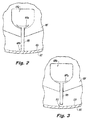
Fig. 2 is a partial cross-sectional view of an embodiment of a sentinel vane in accordance with this disclosure shown in a constant radius portion of the liner and in an unworn condition; -
Fig. 3 is a partial cross-sectional view of an embodiment of a sentinel vane in accordance with this disclosure shown in a constant radius portion of the liner and in a worn condition; -
Fig. 4 is a cross-sectional elevation view of the vane pump ofFig. 1 , shown connected to a vibration sensor; and -
Fig. 5 is a cross-sectional elevation view of the vane pump ofFig. 1 , shown connected to a sensor. - Reference will now be made to the drawings wherein like reference numerals identify similar structural features or aspects of the subject disclosure. For purposes of explanation and illustration, and not limitation, an illustrative view of an embodiment of a vane pump in accordance with the disclosure is shown in
Fig. 1 and is designated generally byreference character 100. Other embodiments and/or aspects of this disclosure are shown inFigs. 2-5 . The systems and methods described herein can be used to provide wear detection for vane pumps before pump failure. - Referring to
Fig. 1 , avane pump 100 includes aliner 101 defining a cammedinner surface 103. As is appreciated by those skilled in the art, the cammedinner surface 103 defines a non-circular cross-section. For example, theliner 101 can include one or moreconstant radius portions 103a, one ormore pumping sections 103b where the radius of the cammedinner surface 103 progressively diminishes, and one ormore filling sections 103c where the radius of the cammedinner surface 103 progressively increases. - A
rotor 105 is rotatably disposed within theliner 103. Therotor 105 has a plurality of vane slots (shown filled withvanes 107, 109). - Referring additionally to
Figs. 2 and 3 , thevane pump 100 also includes a plurality ofvanes rotor 105. Thevanes rotor 105 and contact the cammedinner surface 103 of theliner 101. In certain embodiments, thevanes inner surface 103. In certain embodiments, thevanes inner surface 103. - The plurality of
vanes sentinel vane 109 that are configured to allow detection of wear on the sentinel vane 109 (which can indicate a worn state over thevanes sentinel vane 109 can include abase portion 109a that is larger than its respective vane slot of therotor 105. The base portion can be shaped to have a corresponding contour of anundervane cavity surface 105a. For example, the base portion can be curved as shown. It is contemplated, however, that thebase portion 109a can have any other suitable shape. - As shown between
Figs. 2 and 3 , over time, eachsentinel vane 109 will wear at thetips 109b along withother vanes 107 due to friction from rubbing against theinner cammed surface 103. After thesentinel vane 109 wears a predetermined amount, thebase portion 109a prevents thesentinel vane 109 from extending further from therotor 105 as shown inFig. 3 . This can create agap 111 between asentinel vane tip 109b and a portion of the cammedinner surface 103. For example, the portion of the cammedinner surface 103 where thegap 111 is created can include theconstant radius section 103a (which can be the portion requiring the furthest extension from the rotor. - In certain embodiments, the
vane pump 100 can include plurality of symmetrically located sentinel vanes 109. As shown, the plurality of symmetrically locatedsentinel vanes 109 can include twosentinel vanes 109 spaced 180 degrees circumferentially from each other. In certain embodiments, the plurality of symmetrically locatedsentinel vanes 109 can be spaced circumferentially apart 360/N degrees, wherein N is the total number ofsentinel vanes 109. By spacing thesentinel vanes 109 symmetrically, forces created due to thegaps 111 can be balanced avoiding any potentially detrimental vibration, for example. - Referring to
Fig. 4 , thevane pump 100 can further include avibration sensor 400 operatively connected to therotor 105 to determine when thebase portion 109a ofsentinel vanes 109 contacts therotor 105. Referring toFig. 5 , thevane pump 100 can include asensor 500 operatively connected to thevane pump 100 to sense a pressure pulsation from flow through thegap 111 created between thesentinel van tip 109b and theliner 101. The sensor can additionally or alternatively be operatively connected to thevane pump 100 and/or at least one device (not shown) that is connected to thevane pump 100 to sense a pressure and/or flow loss due to thegap 111. - In accordance with at least one aspect of this disclosure, a method for detecting wear in a
vane pump 100 can include allowing agap 111 to form between asentinel vane tip 109b and aliner 111 in at least one section of the liner as thesentinel vane 109 passes through the at least one section (e.g.,constant radius section 103a). Allowing thegap 111 to form can include restraining abase portion 109b of thesentinel vane 109 within therotor 105 by allowing thebase portion 109a to contact therotor 105 to prevent further outward movement of thesentinel vane 109. - The method can further include detecting a vibration due to the
base portion 109a of thesentinel vane 109 contacting therotor 105. In certain embodiments, the method can include detecting a pressure pulsation due to flow through thegap 111 between thesentinel vane tip 109b and theliner 111. The method can include determining a performance loss of thevane pump 100 due to thegap 111 between thesentinel vane tip 109a and theliner 111. The method can further comprising indicating that thevane pump 100 is in a worn condition (e.g., via a warning light, electronic display, message, or any other suitable indication). - Certain embodiments described above cause a leakage or blowby condition that can be detected either by loss of flow performance (e.g., possibly by observing a reduction in performance of components that are supplied flow from this pump) or a pressure perturbation or vibration signature of a specific frequency (e.g., a multiple of pump speed). For example, the resulting bottoming of the
base portion 109a of thesentinel vanes 109 can produce a vibration signature that may manifest as a "1E" (i.e. one-per-revolution) or "2E" (two-per-revolution) depending on the wear pattern and part tolerances. This can be detected, e.g., by a vibration sensor mounted either on or in close proximity to the pump, rotor, and/or in concert with suitable filtering algorithms. - In certain cases,
sentinel vane tip 109b leakage or blowby may manifest in flow performance loss that could be detected by the loss in performance of another component that uses flow from such avane pump 100 or by manifestation of a system level anomaly (e.g., delayed starting light-off in a jet engine burn flow application). Such conditions may require a built-in-test (BIT) or manual test in which the pump and its powered components are tested in a challenging condition that only pass if the pump was functioning normally. - It is also contemplated that
sentinel vane tip 109b leakage may also manifest in pressure pulsations at 1E frequency or multiples thereof that can be measured by, e.g., a high-response pressure transducer and/or suitable software algorithms. - The methods and systems of the present disclosure, as described above and shown in the drawings, provide for vane pumps with superior properties including wear detection. While the apparatus and methods of the subject disclosure have been shown and described with reference to embodiments, those skilled in the art will readily appreciate that changes and/or modifications may be made thereto without departing from the scope of the subject disclosure.
Claims (15)
- A vane pump (100), comprising:a liner (101) defining a cammed inner surface (103);a rotor (105) rotatably disposed within the liner (103) and including a plurality of vane slots; anda plurality of vanes (107, 109) slidably disposed within vane slots of the rotor (105) and configured to extend away from the rotor (105) and contact the cammed inner surface (103) of the liner (101), wherein the plurality of vanes (107, 109) include at least one sentinel vane (109) that is configured to allow detection of wear on the sentinel vane (109).
- The vane pump (100) of claim 1, wherein the sentinel vane (109) includes a base portion (109a) that is larger than the vane slot of the rotor (105) such that after the sentinel vane (109) wears a predetermined amount, the base portion (109a) prevents the sentinel vane (109) from extending further from the rotor (105) such that a gap (111) separates a sentinel vane tip (109b) and a portion of the cammed inner surface (103).
- The vane pump (100) of claim 2, wherein the portion of the cammed inner surface (103) where the gap (111) is created includes a constant radius section.
- The vane pump of claims 2 or 3, wherein the at least one sentinel vane (109) includes a plurality of symmetrically located sentinel vanes (109).
- The vane pump of claim 4, wherein the plurality of symmetrically located sentinel vanes includes two sentinel vanes (109) spaced 180 degrees circumferentially from each other, or wherein the plurality of symmetrically located sentinel vanes (109) are spaced circumferentially apart 360/N degrees, wherein N is the total number of sentinel vanes.
- The vane pump (100) of any of claims 2-5, further comprising a vibration sensor operatively connected to the rotor (105) to determine when the base portion (109a) of the at least one sentinel vane (109) contacts the rotor (105).
- The vane pump (100) of any of claims 2-6, further comprising a sensor operatively connected to the vane pump (100) to sense a pressure pulsation from flow through the gap (111) created between the sentinel vane tip (109b) and the liner (101).
- The vane pump (100) of any of claims 2-7, further comprising a sensor that is operatively connected to the vane pump (100) and/or at least one device that is connected to the vane pump (100) to sense a pressure loss due to the gap (111).
- A method for detecting wear in a vane pump (100), comprising:allowing a gap (111) to form between a sentinel vane tip (109a) and a liner (101) in at least one section of the liner (101) as the sentinel vane (109) passes through the at least one section.
- The method of claim 9, wherein allowing the gap (111) to form includes restraining a base portion (109a) of the sentinel vane within a rotor (105) by allowing the base portion (109a) to contact the rotor (105) to prevent further outward movement of the sentinel vane (109).
- The method of claims 9 or 10, further comprising detecting a vibration due to the base portion (109a) of the sentinel vane contacting the rotor.
- The method of any of claims 9-11, further comprising detecting a pressure pulsation due to flow through the gap (111) between the sentinel vane tip (109b) and the liner (101), and preferably
further comprising determining a performance loss of the vane pump (100) due to the gap (100) between the sentinel vane tip (109b) and the liner (101), and more preferably further comprising indicating that the vane pump (100) is in a worn condition. - A sentinel vane (109) for a vane pump (100), comprising:a body configured to slide within a vane slot of a rotor (105), the body defining a tip (109b) and a base portion (109a), wherein the base portion (109a) is wider than a remaining portion of the body to allow the vane to slide radially outward through the vane slot up to the base portion (109a).
- The sentinel vane of claim 13 wherein the base portion (109a) is shaped to have a corresponding contour of an undervane cavity surface.
- The sentinel vane (109) of claim 14, wherein the base portion (109a) is curved.
Applications Claiming Priority (1)
| Application Number | Priority Date | Filing Date | Title |
|---|---|---|---|
| US14/795,338 US9828992B2 (en) | 2015-07-09 | 2015-07-09 | Vane pumps with vane wear detection |
Publications (2)
| Publication Number | Publication Date |
|---|---|
| EP3115549A1 true EP3115549A1 (en) | 2017-01-11 |
| EP3115549B1 EP3115549B1 (en) | 2021-05-05 |
Family
ID=56403995
Family Applications (1)
| Application Number | Title | Priority Date | Filing Date |
|---|---|---|---|
| EP16178593.6A Active EP3115549B1 (en) | 2015-07-09 | 2016-07-08 | Vane pumps |
Country Status (2)
| Country | Link |
|---|---|
| US (1) | US9828992B2 (en) |
| EP (1) | EP3115549B1 (en) |
Families Citing this family (2)
| Publication number | Priority date | Publication date | Assignee | Title |
|---|---|---|---|---|
| EP4253721A1 (en) | 2022-03-31 | 2023-10-04 | Goodrich Corporation | Vane wearing detection |
| DE102023115165A1 (en) * | 2023-06-09 | 2024-12-12 | Schwäbische Hüttenwerke Automotive GmbH | Vane pump with fluid lubrication for a conveyor wheel |
Citations (2)
| Publication number | Priority date | Publication date | Assignee | Title |
|---|---|---|---|---|
| US20020110467A1 (en) * | 2001-01-23 | 2002-08-15 | Henderson Timothy H. | Apparatus for indicating remaining life expectancy of a rotary sliding pump |
| US20040136852A1 (en) * | 2002-10-11 | 2004-07-15 | Innovative Solutions & Support, Inc. | Vacuum pump with fail-safe vanes |
Family Cites Families (6)
| Publication number | Priority date | Publication date | Assignee | Title |
|---|---|---|---|---|
| US3463384A (en) * | 1967-07-26 | 1969-08-26 | Allis Chalmers Mfg Co | Wear sensing means for rotary compressor |
| IT1289811B1 (en) | 1996-12-27 | 1998-10-16 | Varian Spa | METHOD AND DIAGNOSTIC APPARATUS FOR VACUUM PUMP. |
| US7207785B2 (en) | 2000-09-28 | 2007-04-24 | Goodrich Pump & Engine Control Systems, Inc. | Vane pump wear sensor for predicted failure mode |
| US6752604B2 (en) * | 2002-04-30 | 2004-06-22 | Gerald Donald Althouse | Automatic wear indicator for sliding vane vacuum and gas pressure pumps |
| US8564449B2 (en) * | 2010-01-12 | 2013-10-22 | Siemens Energy, Inc. | Open circuit wear sensor for use with a conductive wear counterface |
| JP5252318B2 (en) | 2010-08-27 | 2013-07-31 | 株式会社デンソー | Vane type pump device and leak check system using the same |
-
2015
- 2015-07-09 US US14/795,338 patent/US9828992B2/en active Active
-
2016
- 2016-07-08 EP EP16178593.6A patent/EP3115549B1/en active Active
Patent Citations (2)
| Publication number | Priority date | Publication date | Assignee | Title |
|---|---|---|---|---|
| US20020110467A1 (en) * | 2001-01-23 | 2002-08-15 | Henderson Timothy H. | Apparatus for indicating remaining life expectancy of a rotary sliding pump |
| US20040136852A1 (en) * | 2002-10-11 | 2004-07-15 | Innovative Solutions & Support, Inc. | Vacuum pump with fail-safe vanes |
Also Published As
| Publication number | Publication date |
|---|---|
| US20170009768A1 (en) | 2017-01-12 |
| US9828992B2 (en) | 2017-11-28 |
| EP3115549B1 (en) | 2021-05-05 |
Similar Documents
| Publication | Publication Date | Title |
|---|---|---|
| CN104685163B (en) | Turbine engine comprising means for measuring speed and torque of a shaft of the turbine engine and method for monitoring the shaft | |
| KR101705907B1 (en) | Vane pump | |
| JP6005181B2 (en) | Preventing pump surging in compressors | |
| EP2626516A1 (en) | Turbine assembly and corresponding method of altering a fundamental requency | |
| EP3115549B1 (en) | Vane pumps | |
| CN113195949A (en) | Mechanical seal with sensor | |
| WO2010012655A1 (en) | Leaf seal | |
| US9915518B2 (en) | Clearance measuring sensor with abradable electrode | |
| US20190128272A1 (en) | Journal bearing and rotary machine | |
| EP3176377A1 (en) | Wear indication system and corresponding turbine engine component | |
| EP2715070B1 (en) | Wear pin gap closure detection system for gas turbine engine | |
| JP5925804B2 (en) | Apparatus and method for monitoring a rotor | |
| EP3048343A1 (en) | Multi-stage inter shaft ring seal | |
| CN103620355A (en) | Device and method for measuring blade tip passage times in a turbomachine | |
| CN112888868B (en) | System for axial retention of rolling element bearings | |
| US6913451B2 (en) | Vacuum pump with fail-safe vanes | |
| US6877966B2 (en) | Apparatus for indicating remaining life expectancy of a rotary sliding vane pump | |
| US6769886B2 (en) | Rotary vane pump with vane wear access port and method | |
| EP3236080B1 (en) | Rotary machine system | |
| CN106662101A (en) | Vane pump | |
| RU2572744C1 (en) | Gas turbine bypass engine | |
| US12049827B2 (en) | Vane wearing detection | |
| RU2527850C1 (en) | Method of control over gas turbine engine compressor actuators | |
| EP4345247A1 (en) | Assemblies and methods for controlling lubrication for rotary engine apex seals | |
| KR20170020934A (en) | Variable vane pump |
Legal Events
| Date | Code | Title | Description |
|---|---|---|---|
| PUAI | Public reference made under article 153(3) epc to a published international application that has entered the european phase |
Free format text: ORIGINAL CODE: 0009012 |
|
| STAA | Information on the status of an ep patent application or granted ep patent |
Free format text: STATUS: THE APPLICATION HAS BEEN PUBLISHED |
|
| AK | Designated contracting states |
Kind code of ref document: A1 Designated state(s): AL AT BE BG CH CY CZ DE DK EE ES FI FR GB GR HR HU IE IS IT LI LT LU LV MC MK MT NL NO PL PT RO RS SE SI SK SM TR |
|
| AX | Request for extension of the european patent |
Extension state: BA ME |
|
| STAA | Information on the status of an ep patent application or granted ep patent |
Free format text: STATUS: REQUEST FOR EXAMINATION WAS MADE |
|
| 17P | Request for examination filed |
Effective date: 20170711 |
|
| RBV | Designated contracting states (corrected) |
Designated state(s): AL AT BE BG CH CY CZ DE DK EE ES FI FR GB GR HR HU IE IS IT LI LT LU LV MC MK MT NL NO PL PT RO RS SE SI SK SM TR |
|
| RIC1 | Information provided on ipc code assigned before grant |
Ipc: F04C 28/28 20060101ALI20201007BHEP Ipc: F04C 18/344 20060101ALI20201007BHEP Ipc: F01C 21/08 20060101AFI20201007BHEP |
|
| GRAP | Despatch of communication of intention to grant a patent |
Free format text: ORIGINAL CODE: EPIDOSNIGR1 |
|
| STAA | Information on the status of an ep patent application or granted ep patent |
Free format text: STATUS: GRANT OF PATENT IS INTENDED |
|
| INTG | Intention to grant announced |
Effective date: 20201126 |
|
| GRAS | Grant fee paid |
Free format text: ORIGINAL CODE: EPIDOSNIGR3 |
|
| GRAA | (expected) grant |
Free format text: ORIGINAL CODE: 0009210 |
|
| STAA | Information on the status of an ep patent application or granted ep patent |
Free format text: STATUS: THE PATENT HAS BEEN GRANTED |
|
| AK | Designated contracting states |
Kind code of ref document: B1 Designated state(s): AL AT BE BG CH CY CZ DE DK EE ES FI FR GB GR HR HU IE IS IT LI LT LU LV MC MK MT NL NO PL PT RO RS SE SI SK SM TR |
|
| REG | Reference to a national code |
Ref country code: GB Ref legal event code: FG4D |
|
| REG | Reference to a national code |
Ref country code: CH Ref legal event code: EP |
|
| REG | Reference to a national code |
Ref country code: AT Ref legal event code: REF Ref document number: 1390036 Country of ref document: AT Kind code of ref document: T Effective date: 20210515 |
|
| REG | Reference to a national code |
Ref country code: IE Ref legal event code: FG4D |
|
| REG | Reference to a national code |
Ref country code: DE Ref legal event code: R096 Ref document number: 602016057249 Country of ref document: DE |
|
| REG | Reference to a national code |
Ref country code: LT Ref legal event code: MG9D |
|
| REG | Reference to a national code |
Ref country code: AT Ref legal event code: MK05 Ref document number: 1390036 Country of ref document: AT Kind code of ref document: T Effective date: 20210505 |
|
| PG25 | Lapsed in a contracting state [announced via postgrant information from national office to epo] |
Ref country code: LT Free format text: LAPSE BECAUSE OF FAILURE TO SUBMIT A TRANSLATION OF THE DESCRIPTION OR TO PAY THE FEE WITHIN THE PRESCRIBED TIME-LIMIT Effective date: 20210505 Ref country code: FI Free format text: LAPSE BECAUSE OF FAILURE TO SUBMIT A TRANSLATION OF THE DESCRIPTION OR TO PAY THE FEE WITHIN THE PRESCRIBED TIME-LIMIT Effective date: 20210505 Ref country code: AT Free format text: LAPSE BECAUSE OF FAILURE TO SUBMIT A TRANSLATION OF THE DESCRIPTION OR TO PAY THE FEE WITHIN THE PRESCRIBED TIME-LIMIT Effective date: 20210505 Ref country code: BG Free format text: LAPSE BECAUSE OF FAILURE TO SUBMIT A TRANSLATION OF THE DESCRIPTION OR TO PAY THE FEE WITHIN THE PRESCRIBED TIME-LIMIT Effective date: 20210805 Ref country code: HR Free format text: LAPSE BECAUSE OF FAILURE TO SUBMIT A TRANSLATION OF THE DESCRIPTION OR TO PAY THE FEE WITHIN THE PRESCRIBED TIME-LIMIT Effective date: 20210505 |
|
| PG25 | Lapsed in a contracting state [announced via postgrant information from national office to epo] |
Ref country code: IS Free format text: LAPSE BECAUSE OF FAILURE TO SUBMIT A TRANSLATION OF THE DESCRIPTION OR TO PAY THE FEE WITHIN THE PRESCRIBED TIME-LIMIT Effective date: 20210905 Ref country code: LV Free format text: LAPSE BECAUSE OF FAILURE TO SUBMIT A TRANSLATION OF THE DESCRIPTION OR TO PAY THE FEE WITHIN THE PRESCRIBED TIME-LIMIT Effective date: 20210505 Ref country code: GR Free format text: LAPSE BECAUSE OF FAILURE TO SUBMIT A TRANSLATION OF THE DESCRIPTION OR TO PAY THE FEE WITHIN THE PRESCRIBED TIME-LIMIT Effective date: 20210806 Ref country code: NO Free format text: LAPSE BECAUSE OF FAILURE TO SUBMIT A TRANSLATION OF THE DESCRIPTION OR TO PAY THE FEE WITHIN THE PRESCRIBED TIME-LIMIT Effective date: 20210805 Ref country code: PL Free format text: LAPSE BECAUSE OF FAILURE TO SUBMIT A TRANSLATION OF THE DESCRIPTION OR TO PAY THE FEE WITHIN THE PRESCRIBED TIME-LIMIT Effective date: 20210505 Ref country code: PT Free format text: LAPSE BECAUSE OF FAILURE TO SUBMIT A TRANSLATION OF THE DESCRIPTION OR TO PAY THE FEE WITHIN THE PRESCRIBED TIME-LIMIT Effective date: 20210906 Ref country code: ES Free format text: LAPSE BECAUSE OF FAILURE TO SUBMIT A TRANSLATION OF THE DESCRIPTION OR TO PAY THE FEE WITHIN THE PRESCRIBED TIME-LIMIT Effective date: 20210505 Ref country code: SE Free format text: LAPSE BECAUSE OF FAILURE TO SUBMIT A TRANSLATION OF THE DESCRIPTION OR TO PAY THE FEE WITHIN THE PRESCRIBED TIME-LIMIT Effective date: 20210505 Ref country code: RS Free format text: LAPSE BECAUSE OF FAILURE TO SUBMIT A TRANSLATION OF THE DESCRIPTION OR TO PAY THE FEE WITHIN THE PRESCRIBED TIME-LIMIT Effective date: 20210505 |
|
| REG | Reference to a national code |
Ref country code: NL Ref legal event code: MP Effective date: 20210505 |
|
| PG25 | Lapsed in a contracting state [announced via postgrant information from national office to epo] |
Ref country code: NL Free format text: LAPSE BECAUSE OF FAILURE TO SUBMIT A TRANSLATION OF THE DESCRIPTION OR TO PAY THE FEE WITHIN THE PRESCRIBED TIME-LIMIT Effective date: 20210505 |
|
| PG25 | Lapsed in a contracting state [announced via postgrant information from national office to epo] |
Ref country code: SK Free format text: LAPSE BECAUSE OF FAILURE TO SUBMIT A TRANSLATION OF THE DESCRIPTION OR TO PAY THE FEE WITHIN THE PRESCRIBED TIME-LIMIT Effective date: 20210505 Ref country code: SM Free format text: LAPSE BECAUSE OF FAILURE TO SUBMIT A TRANSLATION OF THE DESCRIPTION OR TO PAY THE FEE WITHIN THE PRESCRIBED TIME-LIMIT Effective date: 20210505 Ref country code: CZ Free format text: LAPSE BECAUSE OF FAILURE TO SUBMIT A TRANSLATION OF THE DESCRIPTION OR TO PAY THE FEE WITHIN THE PRESCRIBED TIME-LIMIT Effective date: 20210505 Ref country code: DK Free format text: LAPSE BECAUSE OF FAILURE TO SUBMIT A TRANSLATION OF THE DESCRIPTION OR TO PAY THE FEE WITHIN THE PRESCRIBED TIME-LIMIT Effective date: 20210505 Ref country code: EE Free format text: LAPSE BECAUSE OF FAILURE TO SUBMIT A TRANSLATION OF THE DESCRIPTION OR TO PAY THE FEE WITHIN THE PRESCRIBED TIME-LIMIT Effective date: 20210505 Ref country code: RO Free format text: LAPSE BECAUSE OF FAILURE TO SUBMIT A TRANSLATION OF THE DESCRIPTION OR TO PAY THE FEE WITHIN THE PRESCRIBED TIME-LIMIT Effective date: 20210505 |
|
| REG | Reference to a national code |
Ref country code: DE Ref legal event code: R097 Ref document number: 602016057249 Country of ref document: DE |
|
| REG | Reference to a national code |
Ref country code: CH Ref legal event code: PL |
|
| PLBE | No opposition filed within time limit |
Free format text: ORIGINAL CODE: 0009261 |
|
| STAA | Information on the status of an ep patent application or granted ep patent |
Free format text: STATUS: NO OPPOSITION FILED WITHIN TIME LIMIT |
|
| PG25 | Lapsed in a contracting state [announced via postgrant information from national office to epo] |
Ref country code: MC Free format text: LAPSE BECAUSE OF FAILURE TO SUBMIT A TRANSLATION OF THE DESCRIPTION OR TO PAY THE FEE WITHIN THE PRESCRIBED TIME-LIMIT Effective date: 20210505 |
|
| REG | Reference to a national code |
Ref country code: BE Ref legal event code: MM Effective date: 20210731 |
|
| 26N | No opposition filed |
Effective date: 20220208 |
|
| PG25 | Lapsed in a contracting state [announced via postgrant information from national office to epo] |
Ref country code: LI Free format text: LAPSE BECAUSE OF NON-PAYMENT OF DUE FEES Effective date: 20210731 Ref country code: CH Free format text: LAPSE BECAUSE OF NON-PAYMENT OF DUE FEES Effective date: 20210731 |
|
| PG25 | Lapsed in a contracting state [announced via postgrant information from national office to epo] |
Ref country code: IS Free format text: LAPSE BECAUSE OF FAILURE TO SUBMIT A TRANSLATION OF THE DESCRIPTION OR TO PAY THE FEE WITHIN THE PRESCRIBED TIME-LIMIT Effective date: 20210905 Ref country code: LU Free format text: LAPSE BECAUSE OF NON-PAYMENT OF DUE FEES Effective date: 20210708 Ref country code: AL Free format text: LAPSE BECAUSE OF FAILURE TO SUBMIT A TRANSLATION OF THE DESCRIPTION OR TO PAY THE FEE WITHIN THE PRESCRIBED TIME-LIMIT Effective date: 20210505 |
|
| PG25 | Lapsed in a contracting state [announced via postgrant information from national office to epo] |
Ref country code: IT Free format text: LAPSE BECAUSE OF FAILURE TO SUBMIT A TRANSLATION OF THE DESCRIPTION OR TO PAY THE FEE WITHIN THE PRESCRIBED TIME-LIMIT Effective date: 20210505 Ref country code: IE Free format text: LAPSE BECAUSE OF NON-PAYMENT OF DUE FEES Effective date: 20210708 Ref country code: BE Free format text: LAPSE BECAUSE OF NON-PAYMENT OF DUE FEES Effective date: 20210731 |
|
| PG25 | Lapsed in a contracting state [announced via postgrant information from national office to epo] |
Ref country code: HU Free format text: LAPSE BECAUSE OF FAILURE TO SUBMIT A TRANSLATION OF THE DESCRIPTION OR TO PAY THE FEE WITHIN THE PRESCRIBED TIME-LIMIT; INVALID AB INITIO Effective date: 20160708 |
|
| P01 | Opt-out of the competence of the unified patent court (upc) registered |
Effective date: 20230522 |
|
| PG25 | Lapsed in a contracting state [announced via postgrant information from national office to epo] |
Ref country code: CY Free format text: LAPSE BECAUSE OF FAILURE TO SUBMIT A TRANSLATION OF THE DESCRIPTION OR TO PAY THE FEE WITHIN THE PRESCRIBED TIME-LIMIT Effective date: 20210505 |
|
| PG25 | Lapsed in a contracting state [announced via postgrant information from national office to epo] |
Ref country code: MK Free format text: LAPSE BECAUSE OF FAILURE TO SUBMIT A TRANSLATION OF THE DESCRIPTION OR TO PAY THE FEE WITHIN THE PRESCRIBED TIME-LIMIT Effective date: 20210505 |
|
| PG25 | Lapsed in a contracting state [announced via postgrant information from national office to epo] |
Ref country code: TR Free format text: LAPSE BECAUSE OF FAILURE TO SUBMIT A TRANSLATION OF THE DESCRIPTION OR TO PAY THE FEE WITHIN THE PRESCRIBED TIME-LIMIT Effective date: 20210505 |
|
| PG25 | Lapsed in a contracting state [announced via postgrant information from national office to epo] |
Ref country code: MT Free format text: LAPSE BECAUSE OF FAILURE TO SUBMIT A TRANSLATION OF THE DESCRIPTION OR TO PAY THE FEE WITHIN THE PRESCRIBED TIME-LIMIT Effective date: 20210505 |
|
| PGFP | Annual fee paid to national office [announced via postgrant information from national office to epo] |
Ref country code: GB Payment date: 20250619 Year of fee payment: 10 |
|
| PGFP | Annual fee paid to national office [announced via postgrant information from national office to epo] |
Ref country code: FR Payment date: 20250619 Year of fee payment: 10 |
|
| PGFP | Annual fee paid to national office [announced via postgrant information from national office to epo] |
Ref country code: DE Payment date: 20250620 Year of fee payment: 10 |