EP3115330A1 - Vibration damper for elevator linear propulsion system - Google Patents
Vibration damper for elevator linear propulsion system Download PDFInfo
- Publication number
- EP3115330A1 EP3115330A1 EP16178845.0A EP16178845A EP3115330A1 EP 3115330 A1 EP3115330 A1 EP 3115330A1 EP 16178845 A EP16178845 A EP 16178845A EP 3115330 A1 EP3115330 A1 EP 3115330A1
- Authority
- EP
- European Patent Office
- Prior art keywords
- rail
- engaged
- car
- set forth
- damper
- Prior art date
- Legal status (The legal status is an assumption and is not a legal conclusion. Google has not performed a legal analysis and makes no representation as to the accuracy of the status listed.)
- Granted
Links
- 239000002131 composite material Substances 0.000 claims description 4
- 239000004033 plastic Substances 0.000 claims description 4
- 229920003023 plastic Polymers 0.000 claims description 4
- XAGFODPZIPBFFR-UHFFFAOYSA-N aluminium Chemical compound [Al] XAGFODPZIPBFFR-UHFFFAOYSA-N 0.000 claims description 3
- 229910052782 aluminium Inorganic materials 0.000 claims description 3
- 239000003351 stiffener Substances 0.000 description 5
- 230000000712 assembly Effects 0.000 description 4
- 238000000429 assembly Methods 0.000 description 4
- JOYRKODLDBILNP-UHFFFAOYSA-N Ethyl urethane Chemical compound CCOC(N)=O JOYRKODLDBILNP-UHFFFAOYSA-N 0.000 description 1
- 229920002430 Fibre-reinforced plastic Polymers 0.000 description 1
- 229920002063 Sorbothane Polymers 0.000 description 1
- 230000002411 adverse Effects 0.000 description 1
- 230000004075 alteration Effects 0.000 description 1
- 239000003990 capacitor Substances 0.000 description 1
- 239000004020 conductor Substances 0.000 description 1
- 230000001419 dependent effect Effects 0.000 description 1
- 238000006073 displacement reaction Methods 0.000 description 1
- 229920001971 elastomer Polymers 0.000 description 1
- 239000000806 elastomer Substances 0.000 description 1
- 239000011151 fibre-reinforced plastic Substances 0.000 description 1
- 239000011152 fibreglass Substances 0.000 description 1
- 230000004907 flux Effects 0.000 description 1
- 230000001771 impaired effect Effects 0.000 description 1
- 239000000696 magnetic material Substances 0.000 description 1
- 239000000463 material Substances 0.000 description 1
- 239000012811 non-conductive material Substances 0.000 description 1
- 238000004806 packaging method and process Methods 0.000 description 1
- 230000000135 prohibitive effect Effects 0.000 description 1
- 238000006467 substitution reaction Methods 0.000 description 1
- 229920001169 thermoplastic Polymers 0.000 description 1
- 239000004416 thermosoftening plastic Substances 0.000 description 1
- 125000000391 vinyl group Chemical group [H]C([*])=C([H])[H] 0.000 description 1
- 229920002554 vinyl polymer Polymers 0.000 description 1
- 238000004804 winding Methods 0.000 description 1
Images




Classifications
-
- B—PERFORMING OPERATIONS; TRANSPORTING
- B66—HOISTING; LIFTING; HAULING
- B66B—ELEVATORS; ESCALATORS OR MOVING WALKWAYS
- B66B11/00—Main component parts of lifts in, or associated with, buildings or other structures
- B66B11/04—Driving gear ; Details thereof, e.g. seals
- B66B11/0407—Driving gear ; Details thereof, e.g. seals actuated by an electrical linear motor
-
- B—PERFORMING OPERATIONS; TRANSPORTING
- B66—HOISTING; LIFTING; HAULING
- B66B—ELEVATORS; ESCALATORS OR MOVING WALKWAYS
- B66B5/00—Applications of checking, fault-correcting, or safety devices in elevators
-
- B—PERFORMING OPERATIONS; TRANSPORTING
- B66—HOISTING; LIFTING; HAULING
- B66B—ELEVATORS; ESCALATORS OR MOVING WALKWAYS
- B66B7/00—Other common features of elevators
- B66B7/02—Guideways; Guides
- B66B7/04—Riding means, e.g. Shoes, Rollers, between car and guiding means, e.g. rails, ropes
- B66B7/041—Riding means, e.g. Shoes, Rollers, between car and guiding means, e.g. rails, ropes including active attenuation system for shocks, vibrations
- B66B7/044—Riding means, e.g. Shoes, Rollers, between car and guiding means, e.g. rails, ropes including active attenuation system for shocks, vibrations with magnetic or electromagnetic means
-
- B—PERFORMING OPERATIONS; TRANSPORTING
- B66—HOISTING; LIFTING; HAULING
- B66B—ELEVATORS; ESCALATORS OR MOVING WALKWAYS
- B66B9/00—Kinds or types of lifts in, or associated with, buildings or other structures
- B66B9/003—Kinds or types of lifts in, or associated with, buildings or other structures for lateral transfer of car or frame, e.g. between vertical hoistways or to/from a parking position
-
- B—PERFORMING OPERATIONS; TRANSPORTING
- B66—HOISTING; LIFTING; HAULING
- B66B—ELEVATORS; ESCALATORS OR MOVING WALKWAYS
- B66B9/00—Kinds or types of lifts in, or associated with, buildings or other structures
- B66B9/02—Kinds or types of lifts in, or associated with, buildings or other structures actuated mechanically otherwise than by rope or cable
-
- H—ELECTRICITY
- H02—GENERATION; CONVERSION OR DISTRIBUTION OF ELECTRIC POWER
- H02K—DYNAMO-ELECTRIC MACHINES
- H02K5/00—Casings; Enclosures; Supports
- H02K5/24—Casings; Enclosures; Supports specially adapted for suppression or reduction of noise or vibrations
Definitions
- the subject matter disclosed herein relates generally to the field of elevators, and more particularly to a multicar, self-propelled elevator system having a linear propulsion system.
- Self-propelled elevator systems also referred to as ropeless elevator systems, are useful in certain applications (e.g., high rise buildings) where the mass of the ropes for a roped system is prohibitive and there is a desire for multiple elevator cars to travel in a single lane.
- Existing self-propelled elevators employ linear motors having secondary portions that include permanent magnets embedded in a rail-like structure.
- the secondary portions are typically under high dynamic forces due to the magnetic structures. These forces may induce vibrations that excite resonances (modes) of the structure. Any vibration may deform the secondary portion, which in turn affects air gap widths between moving structures that may negatively impact thrust and/or adversely impact ride quality.
- a linear propulsion assembly for imparting a force upon a car in a hoistway of an elevator system
- the linear propulsion assembly comprises a primary portion constructed and arranged to mount to one of the car and the hoistway, the primary portion including a plurality of electric coils; a secondary portion constructed and arranged to mount to the other of the car and the hoistway, the secondary portion including a rail and plurality of magnets engaged to the rail and for moving the secondary portion with respect to the primary portion; and a leaf damper in contact with the rail for dissipating vibration.
- further embodiments could include the rail including a first side through which the plurality of magnets are exposed and an opposite second side engaged to the leaf damper.
- leaf damper being a composite that includes a plurality of layers.
- leaf damper including a first non-magnetic layer and a first viscoelastic layer disposed between the second side and the non-magnetic layer.
- leaf damper including a second non-magnetic layer directly engaged between the second side and the first viscoelastic layer.
- leaf damper including a third non-magnetic layer and a second viscoelastic layer engaged directly between the first and third non-magnetic layers.
- further embodiments could include the plurality of layers including a plurality of viscoelastic layers and a plurality of rigidity layers respectively interposed between the plurality of viscoelastic layers.
- an elevator system comprises a stationary support structure defining a hoistway; a car disposed in the hoistway; a linear propulsion assembly for applying a force to the car, the assembly including a first rail engaged to one of the support structure and the car, a plurality of magnets mounted to the first rail, a second rail co-extending with and spaced laterally from the first rail and engaged to the other of the support structure and the car, and a plurality of electric coils mounted to the second rail; and a damper engaged to at least one of the first and second rails for dissipating vibration.
- damper being elongated and co-extending longitudinally with the first and second rails.
- damper being passive and engaged to the first rail.
- further embodiments could include the plurality of magnets being approximate to a first side of the first rail and the damper being adhered to an opposite second side of the first rail.
- damper being a leaf damper
- damper including a plurality of viscoelastic layers and a plurality of stiffener layers with each viscoelastic layer adhered to at least one respective stiffener layer.
- damper including a plurality of viscoelastic layers and a plurality of stiffener layers with each viscoelastic layer adhered to at least one respective stiffener layer.
- further embodiments could include a plurality of brackets spaced longitudinally along the first rail with each bracket engaged between the car and the first rail, and wherein the damper extends longitudinally between two adjacent brackets of the plurality of brackets.
- each one of the plurality of stiffener and viscoelastic layers being about equal to or less than 1 mm thick.
- an elevator system 20 may include a stationary support structure 22 that may generally be an integral part of a multi-story building, and at least one lane or hoistway (i.e., three hoistways 24, 26, 28 illustrated) having boundaries generally defined by the structure 22.
- the system 20 further includes at least one car 30 that travels within at least one of the hoistways 24, 26, 28.
- the car 30 may travel in a vertical direction, and may further be in a dedicated upward direction in hoistway 26 and a dedicated downward direction in hoistway 28 (as one, non-limiting, example). It is further contemplated and understood that the elevator system 20 may be self-propelled, and may have multiple cars 30 traveling in any one hoistway 24, 26, 28 with the multiple cars traveling in an upward direction in hoistway 26 and a downward direction in hoistway 28.
- the elevator system 20 may further include upper and lower transfer stations 32, 34 generally located at or above the top floor and at or below the bottom floor, respectively. Both stations 32, 34 may impart horizontal movement of the cars 30, thereby facilitating transfer of the cars between hoistways 24, 26, 28. Although not shown in FIG. 1 , one or more intermediate transfer stations, similar to stations 32, 34, may be used between the first floor and the top floor.
- At least one linear propulsion assembly 36 of the elevator system 20 is generally engaged between the cars 30 and the stationary support structure 22.
- a magnetic field generated by the assembly 36 generally propels the cars 30 within the hoistways 24, 26, 28 and, potentially, the transfer stations 32, 34.
- Each car 30 may further be propelled with two assemblies 36 mounted between opposite sides of the car 30 and opposing walls of the support structure 22.
- Each assembly 36 may include a primary portion 38 engaged to the support structure 22, and two moving, secondary portions 40 engaged to the cars 30.
- the primary portion 38 may be located between and spaced laterally inward from the two secondary portions 40. Both portions 38, 40 are elongated and extend longitudinally in the direction of car travel. It is further contemplated and understood that positioning of the portions 38, 40 may be interchanged with the primary portion 38 engaged to the car 30 and the secondary portion 40 engaged to the support structure 22.
- the primary portion 38 may include a plurality of electric windings or coils 42 and a rail 44 that extends along the direction of car travel.
- the rail 44 may be composed of a plurality of panels 46 for structural support and mounting of the coils 42.
- the coils 42 and panels 46 may be modular in form and may include any variety of configurations necessary to generate the magnetic flux that imparts force on the secondary portion 40 to move or hold the car 30.
- Each secondary portion 40 may include a plurality of permanent magnets 48 and a rail 50 for supporting the magnets.
- the rail 44 of the primary portion 38 may be spaced laterally between the rails 50 of the two secondary portions 40. It is further contemplated and understood that the rail 50 of the secondary portion 40 may be orientated between two rails 44 of the primary portion 38.
- the primary portion 38 may include a plurality of modular assemblies 52 with each assembly including at least one panel 46 of the rail 44 and a portion of the coils 42 supported by the panel. Two modular assemblies 52 may be arranged so that the coils 42 are adjacent to each other and positioned between two secondary portions 40 (see FIG. 3 ).
- Each panel 46 may include a plurality of mounting holes 54 formed therein.
- Coil cores 56 of the primary assembly 38 support the coils 42, and are secured at the mounting holes 54 via fasteners.
- Electrical conductors 58 extend from each coil 42 and may be routed through a common bus (not shown).
- the mounting panels 46 and coil cores 56 may be made from a non-conductive material, such as fiberglass, or plastic which may include fiber reinforced plastic.
- the drive system 60 includes one or more power sources 62 coupled to one or more drives 64 via one or more buses 66.
- the power sources 62 are DC power sources, but embodiments are not limited to using DC power.
- DC power sources 62 may be implemented using storage devices (e.g., batteries, capacitors), and may be active devices that condition power from another source (e.g., rectifiers).
- Drives 64 receive DC power from the DC buses 66 and provide drive signals to the primary portions 38 of the linear propulsion assembly 36.
- Each drive 64 may be a converter that converts DC power from DC bus 66 to a multiphase (e.g., three phase) drive signal provided to a respective section of the primary portions 38.
- the primary portion 38 may be divided into the plurality of modular assemblies 52, with each assembly associated with a respective drive 64.
- a controller 68 provides control signals to the each of the drives 64 to control generation of the drive signals. Controller 68 may use pulse width modulation (PWM) control signals to control generation of the drive signals by drives 64. Controller 68 may be implemented using a processor-based device programmed to generate the control signals. Controller 68 may also be part of an elevator control system or elevator management system. Elements of FIG. 6 may be implemented in a single, integrated module, and/or be distributed along the hoistways 24, 26, 28.
- PWM pulse width modulation
- two opposing secondary portions 40 are illustrated each having a rail 50 and a plurality of permanent magnets 48.
- the rails 50 are substantially parallel to one-another and each have first side 70 and an opposite second side 72.
- the magnets 48 are approximate to the first side 70 and may be exposed therethrough.
- the first sides 70 of the rails 50 of each portion 40 are spaced from and oppose one-another thereby defining a gap 74 for receipt of at least a part of the primary portion 38.
- the width of the gap 74 (i.e., distance between the opposing first sides) is generally greater than the width of the primary portion 38 for maintaining an air space between the sides 70 and the panels 46 of the primary portion 38.
- the linear propulsion assembly 36 may further have an elongated mounting member 76 that co-extends with the rails 50, and a plurality of brackets 78 for securing both secondary portions 40 to the car 30. More specifically, the member 76 may secure directly to the car 30, and the brackets 78 may secure both of the rails 50 to the common member 76. Each bracket 78 may be spaced longitudinally along the rails from the next adjacent bracket and may be engaged directly to the second side 72 of each rail 50. The brackets 78 facilitate proper positioning of the rails 50 and add a degree of structural rigidity to maintain a consistent width of the gap 74. It is further contemplated and understood that the rail 50 of the secondary portion 40 may be orientated between two rails 44 of the primary portion 38.
- the secondary portion 40 includes a plurality of leaf dampers 80 that dissipate vibration energy in shear (i.e., as the secondary portion 40 tries to flex) caused by the high dynamic forces due to the magnetic structures.
- Each damper 80 may be in contact with and/or adhered to the second side 72 of the rail 50; may be located between respective brackets 78; and, may co-extend longitudinally with the rail 50.
- Opposite ends of each damper 80 may be contoured to form over at least a portion of the brackets 78 (not shown), or, may be located adjacent to the respective brackets.
- the leaf damper 80 may include three rigid layers 82A, 82B, 82C that add a degree of structural rigidity and/or stiffness, and two viscoelastic layers 84A, 84B for dissipating vibration. Combined, all of the layers 82, 84 generally form a composite structure (i.e., sandwiching of different layers).
- the rigid layer 82A has a first side that may be adhered to the second side 72 of the rail 50, and an opposite second side that adheres to the viscoelastic layer 84A.
- the viscoelastic layer 84A is located between and may be directly engaged to the adjacent rigid layers 82A, 82B.
- the viscoelastic layer 84B is located between and may be directly engaged to the adjacent rigid layers 82B, 82C.
- the viscoelastic layers 84 are made of a generally rubber-like material (e.g., elastomers such as urethane, thermoplastic vinyls, sorbothane, and others), and the rigid layers 82 may be made of a non-magnetic material such as, for example, an aluminum or a plastic composite material.
- Each layer 84 may be about equal to or less than one millimeter thickness. It is further contemplated and understood that the number of layers 82, 84 may be less or more than that illustrated and the dimensions such as layer thickness and width are dependent upon a specific application while attempting to reduce or minimize overall weight and packaging volume. It is also understood that the leaf damper 80 may be applied to any variety of locations on either rails 44, 50.
- the leaf damper 80 dissipates vibration energy in shear and the added thickness of the leaf damper adds flexural stiffness to the rail 50, reducing the overall vibration of the secondary portion 40 of the linear propulsion assembly 36.
- the secondary portions 40 of the assembly 36 are placed under high dynamic forces due to the magnetic structures.
- the leaf dampers 80 function to attenuate or dissipate resonating vibrations that would otherwise be created by the forces. Therefore, as the car 30 accelerates, the leaf dampers 80 prevent or greatly minimize any vibration resonances placed upon the secondary portions 40. Without such vibrational displacement, the rails 50 will not appreciably deform, and in-turn, the gap 74 width is maintained. With a consistent gap width, thrust of the car 30 is not impaired and ride quality is optimized.
Landscapes
- Engineering & Computer Science (AREA)
- Structural Engineering (AREA)
- Mechanical Engineering (AREA)
- Automation & Control Theory (AREA)
- Civil Engineering (AREA)
- Power Engineering (AREA)
- Physics & Mathematics (AREA)
- Electromagnetism (AREA)
- Cage And Drive Apparatuses For Elevators (AREA)
- Types And Forms Of Lifts (AREA)
- Lift-Guide Devices, And Elevator Ropes And Cables (AREA)
- Vibration Prevention Devices (AREA)
Abstract
Description
- The subject matter disclosed herein relates generally to the field of elevators, and more particularly to a multicar, self-propelled elevator system having a linear propulsion system.
- Self-propelled elevator systems, also referred to as ropeless elevator systems, are useful in certain applications (e.g., high rise buildings) where the mass of the ropes for a roped system is prohibitive and there is a desire for multiple elevator cars to travel in a single lane. There exist self-propelled elevator systems in which a first lane is designated for upward traveling elevator cars and a second lane is designated for downward traveling elevator cars. At least one transfer station is provided in the hoistway to move cars horizontally between the first lane and second lane.
- Existing self-propelled elevators employ linear motors having secondary portions that include permanent magnets embedded in a rail-like structure. The secondary portions are typically under high dynamic forces due to the magnetic structures. These forces may induce vibrations that excite resonances (modes) of the structure. Any vibration may deform the secondary portion, which in turn affects air gap widths between moving structures that may negatively impact thrust and/or adversely impact ride quality.
- According to one, non-limiting, embodiment, a linear propulsion assembly for imparting a force upon a car in a hoistway of an elevator system, the linear propulsion assembly comprises a primary portion constructed and arranged to mount to one of the car and the hoistway, the primary portion including a plurality of electric coils; a secondary portion constructed and arranged to mount to the other of the car and the hoistway, the secondary portion including a rail and plurality of magnets engaged to the rail and for moving the secondary portion with respect to the primary portion; and a leaf damper in contact with the rail for dissipating vibration.
- In addition to one or more of the features described above or below, or as an alternative, further embodiments could include the rail including a first side through which the plurality of magnets are exposed and an opposite second side engaged to the leaf damper.
- In addition to one or more of the features described above or below, or as an alternative, further embodiments could include the leaf damper being a composite that includes a plurality of layers.
- In addition to one or more of the features described above or below, or as an alternative, further embodiments could include the leaf damper including a first non-magnetic layer and a first viscoelastic layer disposed between the second side and the non-magnetic layer.
- In addition to one or more of the features described above or below, or as an alternative, further embodiments could include the leaf damper including a second non-magnetic layer directly engaged between the second side and the first viscoelastic layer.
- In addition to one or more of the features described above or below, or as an alternative, further embodiments could include the leaf damper including a third non-magnetic layer and a second viscoelastic layer engaged directly between the first and third non-magnetic layers.
- In addition to one or more of the features described above or below, or as an alternative, further embodiments could include the plurality of layers including a plurality of viscoelastic layers and a plurality of rigidity layers respectively interposed between the plurality of viscoelastic layers.
- In addition to one or more of the features described above or below, or as an alternative, further embodiments could include the plurality of rigidity layers being made of aluminum.
- In addition to one or more of the features described above or below, or as an alternative, further embodiments could include the plurality of rigidity layers being made at least in-part of plastic.
- According to another, non-limiting, embodiment, an elevator system comprises a stationary support structure defining a hoistway; a car disposed in the hoistway; a linear propulsion assembly for applying a force to the car, the assembly including a first rail engaged to one of the support structure and the car, a plurality of magnets mounted to the first rail, a second rail co-extending with and spaced laterally from the first rail and engaged to the other of the support structure and the car, and a plurality of electric coils mounted to the second rail; and a damper engaged to at least one of the first and second rails for dissipating vibration.
- In addition to one or more of the features described above or below, or as an alternative, further embodiments could include the damper being elongated and co-extending longitudinally with the first and second rails.
- In addition to one or more of the features described above or below, or as an alternative, further embodiments could include the damper being passive and engaged to the first rail.
- In addition to one or more of the features described above or below, or as an alternative, further embodiments could include the first rail being engaged to the car and the second rail being engaged to the support structure.
- In addition to one or more of the features described above or below, or as an alternative, further embodiments could include the plurality of magnets being approximate to a first side of the first rail and the damper being adhered to an opposite second side of the first rail.
- In addition to one or more of the features described above or below, or as an alternative, further embodiments could include the damper being a leaf damper.
- In addition to one or more of the features described above or below, or as an alternative, further embodiments could include the damper including a plurality of viscoelastic layers and a plurality of stiffener layers with each viscoelastic layer adhered to at least one respective stiffener layer.
- In addition to one or more of the features described above or below, or as an alternative, further embodiments could include the damper including a plurality of viscoelastic layers and a plurality of stiffener layers with each viscoelastic layer adhered to at least one respective stiffener layer.
- In addition to one or more of the features described above or below, or as an alternative, further embodiments could include a plurality of brackets spaced longitudinally along the first rail with each bracket engaged between the car and the first rail, and wherein the damper extends longitudinally between two adjacent brackets of the plurality of brackets.
- In addition to one or more of the features described above or below, or as an alternative, further embodiments could include each one of the plurality of stiffener and viscoelastic layers being about equal to or less than 1 mm thick.
- The foregoing and other features, and advantages of embodiments are apparent from the following detailed description taken in conjunction with the accompanying drawings in which:
-
FIG. 1 is a side view of a multicar elevator system as one, non-limiting, exemplary embodiment of the present disclosure; -
FIG. 2 is a top-down view of a car and portions of a linear propulsion assembly of the elevator system; -
FIG. 3 is a partial side view of the linear propulsion assembly; -
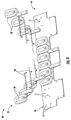
FIG. 4 is a partially exploded perspective view of a primary portion of the linear propulsion assembly; -
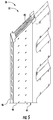
FIG. 5 is a perspective view of the primary portion; -
FIG. 6 is a schematic of a drive system of the elevator system; -
FIG. 7 is a partial perspective view of two secondary portions, a mounting member and brackets of the linear propulsion assembly; and -
FIG. 8 is a cross section of a leaf damper of the linear propulsion assembly taken from line 8-8 inFIG. 7 . - Referring to
FIG. 1 , anelevator system 20 may include astationary support structure 22 that may generally be an integral part of a multi-story building, and at least one lane or hoistway (i.e., threehoistways structure 22. Thesystem 20 further includes at least onecar 30 that travels within at least one of thehoistways car 30 may travel in a vertical direction, and may further be in a dedicated upward direction inhoistway 26 and a dedicated downward direction in hoistway 28 (as one, non-limiting, example). It is further contemplated and understood that theelevator system 20 may be self-propelled, and may havemultiple cars 30 traveling in any onehoistway hoistway 26 and a downward direction inhoistway 28. - The
elevator system 20 may further include upper andlower transfer stations stations cars 30, thereby facilitating transfer of the cars betweenhoistways FIG. 1 , one or more intermediate transfer stations, similar tostations - Referring to
FIGS. 1 and2 , at least onelinear propulsion assembly 36 of theelevator system 20 is generally engaged between thecars 30 and thestationary support structure 22. A magnetic field generated by theassembly 36 generally propels thecars 30 within thehoistways transfer stations car 30 may further be propelled with twoassemblies 36 mounted between opposite sides of thecar 30 and opposing walls of thesupport structure 22. Eachassembly 36 may include aprimary portion 38 engaged to thesupport structure 22, and two moving,secondary portions 40 engaged to thecars 30. Theprimary portion 38 may be located between and spaced laterally inward from the twosecondary portions 40. Bothportions portions primary portion 38 engaged to thecar 30 and thesecondary portion 40 engaged to thesupport structure 22. - Referring to
FIGS. 2 and 3 , theprimary portion 38 may include a plurality of electric windings orcoils 42 and arail 44 that extends along the direction of car travel. Therail 44 may be composed of a plurality ofpanels 46 for structural support and mounting of thecoils 42. Thecoils 42 andpanels 46 may be modular in form and may include any variety of configurations necessary to generate the magnetic flux that imparts force on thesecondary portion 40 to move or hold thecar 30. Eachsecondary portion 40 may include a plurality ofpermanent magnets 48 and arail 50 for supporting the magnets. Therail 44 of theprimary portion 38 may be spaced laterally between therails 50 of the twosecondary portions 40. It is further contemplated and understood that therail 50 of thesecondary portion 40 may be orientated between tworails 44 of theprimary portion 38. - Referring to
FIGS. 4 and5 , theprimary portion 38 may include a plurality ofmodular assemblies 52 with each assembly including at least onepanel 46 of therail 44 and a portion of thecoils 42 supported by the panel. Twomodular assemblies 52 may be arranged so that thecoils 42 are adjacent to each other and positioned between two secondary portions 40 (seeFIG. 3 ). Eachpanel 46 may include a plurality of mountingholes 54 formed therein.Coil cores 56 of theprimary assembly 38 support thecoils 42, and are secured at themounting holes 54 via fasteners.Electrical conductors 58 extend from eachcoil 42 and may be routed through a common bus (not shown). The mountingpanels 46 andcoil cores 56 may be made from a non-conductive material, such as fiberglass, or plastic which may include fiber reinforced plastic. - Referring to
FIG. 6 a schematic illustration of an exemplary embodiment of a drive system 60 of theelevator system 20 is shown. It is understood that other components (e.g., safeties, brakes, etc.) are not shown inFIG. 6 for ease of illustration. The drive system 60 includes one ormore power sources 62 coupled to one ormore drives 64 via one ormore buses 66. Thepower sources 62 are DC power sources, but embodiments are not limited to using DC power.DC power sources 62 may be implemented using storage devices (e.g., batteries, capacitors), and may be active devices that condition power from another source (e.g., rectifiers).Drives 64 receive DC power from theDC buses 66 and provide drive signals to theprimary portions 38 of thelinear propulsion assembly 36. Each drive 64 may be a converter that converts DC power fromDC bus 66 to a multiphase (e.g., three phase) drive signal provided to a respective section of theprimary portions 38. Theprimary portion 38 may be divided into the plurality ofmodular assemblies 52, with each assembly associated with arespective drive 64. - A
controller 68 provides control signals to the each of thedrives 64 to control generation of the drive signals.Controller 68 may use pulse width modulation (PWM) control signals to control generation of the drive signals by drives 64.Controller 68 may be implemented using a processor-based device programmed to generate the control signals.Controller 68 may also be part of an elevator control system or elevator management system. Elements ofFIG. 6 may be implemented in a single, integrated module, and/or be distributed along thehoistways - Referring to
FIGS. 7 and 8 , two opposingsecondary portions 40 are illustrated each having arail 50 and a plurality ofpermanent magnets 48. Therails 50 are substantially parallel to one-another and each havefirst side 70 and an oppositesecond side 72. Themagnets 48 are approximate to thefirst side 70 and may be exposed therethrough. The first sides 70 of therails 50 of eachportion 40 are spaced from and oppose one-another thereby defining agap 74 for receipt of at least a part of theprimary portion 38. The width of the gap 74 (i.e., distance between the opposing first sides) is generally greater than the width of theprimary portion 38 for maintaining an air space between thesides 70 and thepanels 46 of theprimary portion 38. - The
linear propulsion assembly 36 may further have an elongated mountingmember 76 that co-extends with therails 50, and a plurality ofbrackets 78 for securing bothsecondary portions 40 to thecar 30. More specifically, themember 76 may secure directly to thecar 30, and thebrackets 78 may secure both of therails 50 to thecommon member 76. Eachbracket 78 may be spaced longitudinally along the rails from the next adjacent bracket and may be engaged directly to thesecond side 72 of eachrail 50. Thebrackets 78 facilitate proper positioning of therails 50 and add a degree of structural rigidity to maintain a consistent width of thegap 74. It is further contemplated and understood that therail 50 of thesecondary portion 40 may be orientated between tworails 44 of theprimary portion 38. - The
secondary portion 40 includes a plurality ofleaf dampers 80 that dissipate vibration energy in shear (i.e., as thesecondary portion 40 tries to flex) caused by the high dynamic forces due to the magnetic structures. Eachdamper 80 may be in contact with and/or adhered to thesecond side 72 of therail 50; may be located betweenrespective brackets 78; and, may co-extend longitudinally with therail 50. Opposite ends of eachdamper 80 may be contoured to form over at least a portion of the brackets 78 (not shown), or, may be located adjacent to the respective brackets. - The
leaf damper 80 may include threerigid layers viscoelastic layers rigid layer 82A has a first side that may be adhered to thesecond side 72 of therail 50, and an opposite second side that adheres to theviscoelastic layer 84A. Theviscoelastic layer 84A is located between and may be directly engaged to the adjacentrigid layers viscoelastic layer 84B is located between and may be directly engaged to the adjacentrigid layers leaf damper 80 may be applied to any variety of locations on eitherrails - In operation, the
leaf damper 80 dissipates vibration energy in shear and the added thickness of the leaf damper adds flexural stiffness to therail 50, reducing the overall vibration of thesecondary portion 40 of thelinear propulsion assembly 36. During operation of theelevator system 20, thesecondary portions 40 of theassembly 36 are placed under high dynamic forces due to the magnetic structures. Theleaf dampers 80 function to attenuate or dissipate resonating vibrations that would otherwise be created by the forces. Therefore, as thecar 30 accelerates, theleaf dampers 80 prevent or greatly minimize any vibration resonances placed upon thesecondary portions 40. Without such vibrational displacement, therails 50 will not appreciably deform, and in-turn, thegap 74 width is maintained. With a consistent gap width, thrust of thecar 30 is not impaired and ride quality is optimized. - While the present disclosure has been described in detail in connection with only a limited number of embodiments, it should be readily understood that the present disclosure is not limited to such disclosed embodiments. Rather, the present disclosure can be modified to incorporate any number of variations, alterations, substitutions or equivalent arrangements not heretofore described, but which are commensurate in spirit and/or scope. Additionally, while various embodiments have been described, it is to be understood that aspects of the present disclosure may include only some of the described embodiments. Accordingly, the present disclosure is not to be seen as limited by the foregoing description, but is only limited by the scope of the appended claims.
Claims (15)
- A linear propulsion assembly for imparting a force upon a car in a hoistway of an elevator system, the linear propulsion assembly comprising:a primary portion constructed and arranged to mount to one of the car and the hoistway, the primary portion including a plurality of electric coils;a secondary portion constructed and arranged to mount to the other of the car and the hoistway, the secondary portion including a rail and plurality of magnets engaged to the rail and for moving the secondary portion with respect to the primary portion; anda leaf damper in contact with the rail for dissipating vibration.
- The linear propulsion assembly set forth in claim 1, wherein the rail includes a first side through which the plurality of magnets are exposed and an opposite second side engaged to the leaf damper.
- The linear propulsion assembly set forth in claim 1 or 2, wherein the leaf damper is a composite that includes a plurality of layers.
- The linear propulsion assembly set forth in claim 2 or 3, wherein the leaf damper includes a first non-magnetic layer and a first viscoelastic layer disposed between the second side and the first non-magnetic layer.
- The linear propulsion assembly set forth in claim 4, wherein the leaf damper includes a second non-magnetic layer directly engaged between the second side and the first viscoelastic layer.
- The linear propulsion assembly set forth in claim 5, wherein the leaf damper includes a third non-magnetic layer and a second viscoelastic layer engaged directly between the first and third non-magnetic layers
- The linear propulsion assembly set forth in any of claims 3-6, wherein the plurality of layers include a plurality of viscoelastic layers and a plurality of rigidity layers respectively interposed between the plurality of viscoelastic layers.
- The linear propulsion assembly set forth in claim 7, wherein the plurality of rigidity layers are made of aluminum.
- The linear propulsion assembly set forth in claim 7, wherein the plurality of rigidity layers are made at least in-part of plastic.
- An elevator system comprising:a stationary support structure defining a hoistway;a car disposed in the hoistway;a linear propulsion assembly for applying a force to the car, the assembly including a first rail engaged to one of the support structure and the car, a plurality of magnets mounted to the first rail, a second rail co-extending with and spaced laterally from the first rail and engaged to the other of the support structure and the car, and a plurality of electric coils mounted to the second rail; anda damper engaged to at least one of the first and second rails for dissipating vibration.
- The elevator system set forth in claim 10, wherein the damper is elongated and co-extends longitudinally with the first and second rails.
- The elevator system set forth in claim 10 or 11, wherein the damper is passive and engaged to the first rail.
- The elevator system set forth in claim 12, wherein the first rail is engaged to the car and the second rail is engaged to the support structure.
- The elevator system set forth in claim 13, wherein the plurality of magnets are approximate to a first side of the first rail and the damper is adhered to an opposite second side of the first rail.
- The elevator system set forth in claim 14, wherein the damper is a leaf damper.
Applications Claiming Priority (1)
| Application Number | Priority Date | Filing Date | Title |
|---|---|---|---|
| US201562190611P | 2015-07-09 | 2015-07-09 |
Publications (2)
| Publication Number | Publication Date |
|---|---|
| EP3115330A1 true EP3115330A1 (en) | 2017-01-11 |
| EP3115330B1 EP3115330B1 (en) | 2018-09-12 |
Family
ID=56409011
Family Applications (1)
| Application Number | Title | Priority Date | Filing Date |
|---|---|---|---|
| EP16178845.0A Not-in-force EP3115330B1 (en) | 2015-07-09 | 2016-07-11 | Vibration damper for elevator linear propulsion system |
Country Status (4)
| Country | Link |
|---|---|
| US (1) | US10329123B2 (en) |
| EP (1) | EP3115330B1 (en) |
| CN (1) | CN106335835B (en) |
| ES (1) | ES2688383T3 (en) |
Cited By (1)
| Publication number | Priority date | Publication date | Assignee | Title |
|---|---|---|---|---|
| EP3373428A1 (en) * | 2017-03-09 | 2018-09-12 | KONE Corporation | Electric linear motor for an elevator and method for controlling thereof |
Families Citing this family (7)
| Publication number | Priority date | Publication date | Assignee | Title |
|---|---|---|---|---|
| DE102014219862A1 (en) * | 2014-09-30 | 2016-03-31 | Thyssenkrupp Ag | elevator system |
| JP6765319B2 (en) * | 2017-02-27 | 2020-10-07 | 三菱電機株式会社 | Cargo handling machine |
| KR102042927B1 (en) * | 2017-10-31 | 2019-11-11 | 현대엘리베이터주식회사 | Emergency Brake System for Linear Motor Type Elevator |
| KR102095654B1 (en) * | 2018-10-16 | 2020-03-31 | 현대엘리베이터주식회사 | Ropeless Elevator System |
| KR102097873B1 (en) * | 2018-10-16 | 2020-04-06 | 현대엘리베이터주식회사 | Brake System for Linear Motor Type Elevator |
| CN109455591B (en) * | 2019-01-14 | 2024-02-27 | 闽江学院 | Elevator guide rail tabletting distance detection device and working method thereof |
| EP4273083A1 (en) * | 2022-05-04 | 2023-11-08 | TK Escalator Norte, S.A. | Bounce damper for an elevator system |
Citations (2)
| Publication number | Priority date | Publication date | Assignee | Title |
|---|---|---|---|---|
| US20040216960A1 (en) * | 2003-04-14 | 2004-11-04 | Johannes Kocher | Drive with linear motor, elevator with this drive and method of operating this drive |
| US20130270041A1 (en) * | 2010-10-07 | 2013-10-17 | Thyssenkrupp Transrapid Gmbh | Elevator installation |
Family Cites Families (32)
| Publication number | Priority date | Publication date | Assignee | Title |
|---|---|---|---|---|
| DE2345990A1 (en) * | 1970-04-15 | 1975-04-03 | Raoul Dipl Ing Joern | SPRING ELEMENT, IN PARTICULAR FOR THE ELASTIC MOUNTING OF MOTORS |
| CA1250327A (en) * | 1984-03-29 | 1989-02-21 | Dunlop Limited | Spring |
| US4978581A (en) * | 1986-02-07 | 1990-12-18 | Bridgestone Construction | Anti-seismic bearing |
| ATE80123T1 (en) | 1988-07-12 | 1992-09-15 | Inventio Ag | DEVICE FOR ANTI-VIBRATION IN ELEVATOR CABINS. |
| FI884380L (en) | 1988-09-23 | 1990-03-24 | Kone Oy | FOERFARANDE OCH ANORDNING FOER DAEMPANDET AV VIBRATIONER I EN HISSKORG. |
| JPH02241353A (en) | 1989-02-28 | 1990-09-26 | Otis Elevator Co | Air gap adjuster for cylindrical linear motor |
| JPH05186165A (en) * | 1992-01-16 | 1993-07-27 | Mitsubishi Electric Corp | Linear motor drive type elevator device |
| JPH061564A (en) | 1992-06-15 | 1994-01-11 | Kokusai Electric Co Ltd | lift device |
| JPH0692572A (en) | 1992-09-11 | 1994-04-05 | Hitachi Ltd | Rope guide device for oblique elevator |
| US5325937A (en) * | 1993-05-13 | 1994-07-05 | Otis Elevator Company | Elevator platform isolation |
| US5566784A (en) | 1994-07-08 | 1996-10-22 | Otis Elevator Company | Self-propelled elevator system |
| US5749444A (en) * | 1995-10-31 | 1998-05-12 | Otis Elevator Company | Contactless slide guide for elevators |
| US6402044B1 (en) * | 1997-02-03 | 2002-06-11 | Yugen Kaisha Koshinsha | Method of damping railroad noise and railroad noise damping members |
| ATE192118T1 (en) | 1997-02-17 | 2000-05-15 | Thyssen Aufzugswerke Gmbh | LINEAR MOTOR FOR DRIVING AN ELEVATOR CABIN |
| JP4146004B2 (en) | 1998-09-10 | 2008-09-03 | 東芝エレベータ株式会社 | Elevator equipment |
| US6628027B2 (en) * | 2000-12-18 | 2003-09-30 | Siemens Westinghouse Power Corporation | Power generation system including an apparatus for attaching a generator stator core to frame support and associated methods |
| US6498417B2 (en) * | 2000-12-18 | 2002-12-24 | Siemens Westinghouse Power Corporation | Power generation system including an apparatus for low tuning a generator stator core upon attachment to a frame support and associated methods |
| US6604735B2 (en) * | 2000-12-22 | 2003-08-12 | Lockheed Martin Corporation | Elastomer variants |
| JP4350988B2 (en) | 2003-07-14 | 2009-10-28 | 東芝エレベータ株式会社 | Machine roomless elevator |
| SG109535A1 (en) * | 2003-08-14 | 2005-03-30 | Inventio Ag | Electric motor, lift with a cage movable by an electric motor, and lift with a cage and with an electric motor for movement of a guide element relative to the cage |
| SG112944A1 (en) * | 2003-12-22 | 2005-07-28 | Inventio Ag | Equipment for vibration damping of a lift cage |
| NZ552308A (en) * | 2006-02-08 | 2008-11-28 | Inventio Ag | Lift installation with a linear drive system and linear drive system for such a lift installation |
| CN101074077A (en) | 2006-05-19 | 2007-11-21 | 沈阳博林特电梯有限公司 | Tracking-driven elevator system |
| US8302988B2 (en) * | 2008-03-10 | 2012-11-06 | Hendrickson Usa, L.L.C. | Suspension assembly with tie-plate |
| FI20090389A7 (en) | 2009-10-23 | 2011-04-24 | Kone Corp | Method of manufacturing an elevator |
| US8040014B2 (en) * | 2009-11-20 | 2011-10-18 | General Electric Company | Stator core suspension and related spring bar |
| JP5514917B2 (en) * | 2009-12-22 | 2014-06-04 | オーチス エレベータ カンパニー | Elevator system with magnetic brake device |
| JP5859531B2 (en) | 2010-08-06 | 2016-02-10 | コリーエレベーター カンパニー リミテッド | Worm gear type drive unit, elevator using worm gear type drive unit, and elevator system |
| US8513941B2 (en) * | 2011-07-30 | 2013-08-20 | Inno-Tech Co., Ltd. | Power detection regulation device |
| CN203158979U (en) | 2013-03-18 | 2013-08-28 | 重庆迪康电梯有限公司 | Elevator without machine room |
| EP2994408A4 (en) | 2013-05-06 | 2017-01-25 | Otis Elevator Company | Linear motor stator core for self-propelled elevator |
| DE102014219862A1 (en) * | 2014-09-30 | 2016-03-31 | Thyssenkrupp Ag | elevator system |
-
2016
- 2016-07-11 ES ES16178845.0T patent/ES2688383T3/en active Active
- 2016-07-11 CN CN201610542109.7A patent/CN106335835B/en not_active Expired - Fee Related
- 2016-07-11 EP EP16178845.0A patent/EP3115330B1/en not_active Not-in-force
- 2016-07-11 US US15/206,715 patent/US10329123B2/en active Active
Patent Citations (2)
| Publication number | Priority date | Publication date | Assignee | Title |
|---|---|---|---|---|
| US20040216960A1 (en) * | 2003-04-14 | 2004-11-04 | Johannes Kocher | Drive with linear motor, elevator with this drive and method of operating this drive |
| US20130270041A1 (en) * | 2010-10-07 | 2013-10-17 | Thyssenkrupp Transrapid Gmbh | Elevator installation |
Cited By (2)
| Publication number | Priority date | Publication date | Assignee | Title |
|---|---|---|---|---|
| EP3373428A1 (en) * | 2017-03-09 | 2018-09-12 | KONE Corporation | Electric linear motor for an elevator and method for controlling thereof |
| US10574166B2 (en) | 2017-03-09 | 2020-02-25 | Kone Corporation | Electric linear motor for an elevator and method for controlling thereof |
Also Published As
| Publication number | Publication date |
|---|---|
| CN106335835B (en) | 2020-10-02 |
| EP3115330B1 (en) | 2018-09-12 |
| ES2688383T3 (en) | 2018-11-02 |
| US10329123B2 (en) | 2019-06-25 |
| CN106335835A (en) | 2017-01-18 |
| US20170008737A1 (en) | 2017-01-12 |
Similar Documents
| Publication | Publication Date | Title |
|---|---|---|
| EP3115330B1 (en) | Vibration damper for elevator linear propulsion system | |
| ES2836173T3 (en) | Linear electric motor | |
| US20170008736A1 (en) | Active vibration damper for a linear propulsion system of a ropeless elevator | |
| CN106477431B (en) | Elevator car cab isolation | |
| US10118799B2 (en) | Multicar self-propelled elevator system | |
| US10329124B2 (en) | Elevator wireless power supply | |
| US10384914B2 (en) | Elevator support structure | |
| US9906112B2 (en) | Electromagnetic propulsion system having a wireless power transfer system | |
| US10196240B2 (en) | Wireless power supply for self-propelled elevator | |
| US10211676B2 (en) | Electromechanical propulsion system having a wireless power transfer system | |
| KR20150068092A (en) | Magnetic levitation system comprising propulsion electromagnet having guiding function | |
| US11814267B2 (en) | Seal assembly for a pneumatic vacuum elevator | |
| CN103974849A (en) | Drive apparatus for a magnetic levitation transport system | |
| US20190010016A1 (en) | Elevator car position detection assembly | |
| US20180029829A1 (en) | Mechanically integrated propulsion guiding unit | |
| US20160297648A1 (en) | Stator reduction in ropeless elevator transfer station | |
| US20170373552A1 (en) | Mounting assembly for elevator linear propulsion system | |
| CN107074499A (en) | Elevator device | |
| CN107207204A (en) | Buffer unit for elevator with multiple compartments system | |
| JP2013086642A (en) | Power converter for vehicle | |
| CN110939026B (en) | A magnetic levitation track beam | |
| KR101471092B1 (en) | Magnetic levitation system having division invertor |
Legal Events
| Date | Code | Title | Description |
|---|---|---|---|
| PUAI | Public reference made under article 153(3) epc to a published international application that has entered the european phase |
Free format text: ORIGINAL CODE: 0009012 |
|
| STAA | Information on the status of an ep patent application or granted ep patent |
Free format text: STATUS: THE APPLICATION HAS BEEN PUBLISHED |
|
| AK | Designated contracting states |
Kind code of ref document: A1 Designated state(s): AL AT BE BG CH CY CZ DE DK EE ES FI FR GB GR HR HU IE IS IT LI LT LU LV MC MK MT NL NO PL PT RO RS SE SI SK SM TR |
|
| AX | Request for extension of the european patent |
Extension state: BA ME |
|
| STAA | Information on the status of an ep patent application or granted ep patent |
Free format text: STATUS: REQUEST FOR EXAMINATION WAS MADE |
|
| 17P | Request for examination filed |
Effective date: 20170711 |
|
| RBV | Designated contracting states (corrected) |
Designated state(s): AL AT BE BG CH CY CZ DE DK EE ES FI FR GB GR HR HU IE IS IT LI LT LU LV MC MK MT NL NO PL PT RO RS SE SI SK SM TR |
|
| RAP1 | Party data changed (applicant data changed or rights of an application transferred) |
Owner name: OTIS ELEVATOR COMPANY |
|
| GRAP | Despatch of communication of intention to grant a patent |
Free format text: ORIGINAL CODE: EPIDOSNIGR1 |
|
| STAA | Information on the status of an ep patent application or granted ep patent |
Free format text: STATUS: GRANT OF PATENT IS INTENDED |
|
| INTG | Intention to grant announced |
Effective date: 20180309 |
|
| GRAS | Grant fee paid |
Free format text: ORIGINAL CODE: EPIDOSNIGR3 |
|
| GRAA | (expected) grant |
Free format text: ORIGINAL CODE: 0009210 |
|
| STAA | Information on the status of an ep patent application or granted ep patent |
Free format text: STATUS: THE PATENT HAS BEEN GRANTED |
|
| AK | Designated contracting states |
Kind code of ref document: B1 Designated state(s): AL AT BE BG CH CY CZ DE DK EE ES FI FR GB GR HR HU IE IS IT LI LT LU LV MC MK MT NL NO PL PT RO RS SE SI SK SM TR |
|
| REG | Reference to a national code |
Ref country code: GB Ref legal event code: FG4D |
|
| REG | Reference to a national code |
Ref country code: CH Ref legal event code: EP |
|
| REG | Reference to a national code |
Ref country code: IE Ref legal event code: FG4D |
|
| REG | Reference to a national code |
Ref country code: DE Ref legal event code: R096 Ref document number: 602016005477 Country of ref document: DE |
|
| REG | Reference to a national code |
Ref country code: AT Ref legal event code: REF Ref document number: 1040314 Country of ref document: AT Kind code of ref document: T Effective date: 20181015 |
|
| REG | Reference to a national code |
Ref country code: ES Ref legal event code: FG2A Ref document number: 2688383 Country of ref document: ES Kind code of ref document: T3 Effective date: 20181102 |
|
| REG | Reference to a national code |
Ref country code: NL Ref legal event code: MP Effective date: 20180912 |
|
| REG | Reference to a national code |
Ref country code: LT Ref legal event code: MG4D |
|
| PG25 | Lapsed in a contracting state [announced via postgrant information from national office to epo] |
Ref country code: GR Free format text: LAPSE BECAUSE OF FAILURE TO SUBMIT A TRANSLATION OF THE DESCRIPTION OR TO PAY THE FEE WITHIN THE PRESCRIBED TIME-LIMIT Effective date: 20181213 Ref country code: BG Free format text: LAPSE BECAUSE OF FAILURE TO SUBMIT A TRANSLATION OF THE DESCRIPTION OR TO PAY THE FEE WITHIN THE PRESCRIBED TIME-LIMIT Effective date: 20181212 Ref country code: RS Free format text: LAPSE BECAUSE OF FAILURE TO SUBMIT A TRANSLATION OF THE DESCRIPTION OR TO PAY THE FEE WITHIN THE PRESCRIBED TIME-LIMIT Effective date: 20180912 Ref country code: NO Free format text: LAPSE BECAUSE OF FAILURE TO SUBMIT A TRANSLATION OF THE DESCRIPTION OR TO PAY THE FEE WITHIN THE PRESCRIBED TIME-LIMIT Effective date: 20181212 Ref country code: FI Free format text: LAPSE BECAUSE OF FAILURE TO SUBMIT A TRANSLATION OF THE DESCRIPTION OR TO PAY THE FEE WITHIN THE PRESCRIBED TIME-LIMIT Effective date: 20180912 Ref country code: LT Free format text: LAPSE BECAUSE OF FAILURE TO SUBMIT A TRANSLATION OF THE DESCRIPTION OR TO PAY THE FEE WITHIN THE PRESCRIBED TIME-LIMIT Effective date: 20180912 Ref country code: SE Free format text: LAPSE BECAUSE OF FAILURE TO SUBMIT A TRANSLATION OF THE DESCRIPTION OR TO PAY THE FEE WITHIN THE PRESCRIBED TIME-LIMIT Effective date: 20180912 |
|
| PG25 | Lapsed in a contracting state [announced via postgrant information from national office to epo] |
Ref country code: AL Free format text: LAPSE BECAUSE OF FAILURE TO SUBMIT A TRANSLATION OF THE DESCRIPTION OR TO PAY THE FEE WITHIN THE PRESCRIBED TIME-LIMIT Effective date: 20180912 Ref country code: LV Free format text: LAPSE BECAUSE OF FAILURE TO SUBMIT A TRANSLATION OF THE DESCRIPTION OR TO PAY THE FEE WITHIN THE PRESCRIBED TIME-LIMIT Effective date: 20180912 Ref country code: HR Free format text: LAPSE BECAUSE OF FAILURE TO SUBMIT A TRANSLATION OF THE DESCRIPTION OR TO PAY THE FEE WITHIN THE PRESCRIBED TIME-LIMIT Effective date: 20180912 |
|
| REG | Reference to a national code |
Ref country code: AT Ref legal event code: MK05 Ref document number: 1040314 Country of ref document: AT Kind code of ref document: T Effective date: 20180912 |
|
| PG25 | Lapsed in a contracting state [announced via postgrant information from national office to epo] |
Ref country code: EE Free format text: LAPSE BECAUSE OF FAILURE TO SUBMIT A TRANSLATION OF THE DESCRIPTION OR TO PAY THE FEE WITHIN THE PRESCRIBED TIME-LIMIT Effective date: 20180912 Ref country code: PL Free format text: LAPSE BECAUSE OF FAILURE TO SUBMIT A TRANSLATION OF THE DESCRIPTION OR TO PAY THE FEE WITHIN THE PRESCRIBED TIME-LIMIT Effective date: 20180912 Ref country code: IS Free format text: LAPSE BECAUSE OF FAILURE TO SUBMIT A TRANSLATION OF THE DESCRIPTION OR TO PAY THE FEE WITHIN THE PRESCRIBED TIME-LIMIT Effective date: 20190112 Ref country code: CZ Free format text: LAPSE BECAUSE OF FAILURE TO SUBMIT A TRANSLATION OF THE DESCRIPTION OR TO PAY THE FEE WITHIN THE PRESCRIBED TIME-LIMIT Effective date: 20180912 Ref country code: NL Free format text: LAPSE BECAUSE OF FAILURE TO SUBMIT A TRANSLATION OF THE DESCRIPTION OR TO PAY THE FEE WITHIN THE PRESCRIBED TIME-LIMIT Effective date: 20180912 Ref country code: RO Free format text: LAPSE BECAUSE OF FAILURE TO SUBMIT A TRANSLATION OF THE DESCRIPTION OR TO PAY THE FEE WITHIN THE PRESCRIBED TIME-LIMIT Effective date: 20180912 Ref country code: IT Free format text: LAPSE BECAUSE OF FAILURE TO SUBMIT A TRANSLATION OF THE DESCRIPTION OR TO PAY THE FEE WITHIN THE PRESCRIBED TIME-LIMIT Effective date: 20180912 Ref country code: AT Free format text: LAPSE BECAUSE OF FAILURE TO SUBMIT A TRANSLATION OF THE DESCRIPTION OR TO PAY THE FEE WITHIN THE PRESCRIBED TIME-LIMIT Effective date: 20180912 |
|
| PG25 | Lapsed in a contracting state [announced via postgrant information from national office to epo] |
Ref country code: SK Free format text: LAPSE BECAUSE OF FAILURE TO SUBMIT A TRANSLATION OF THE DESCRIPTION OR TO PAY THE FEE WITHIN THE PRESCRIBED TIME-LIMIT Effective date: 20180912 Ref country code: SM Free format text: LAPSE BECAUSE OF FAILURE TO SUBMIT A TRANSLATION OF THE DESCRIPTION OR TO PAY THE FEE WITHIN THE PRESCRIBED TIME-LIMIT Effective date: 20180912 Ref country code: PT Free format text: LAPSE BECAUSE OF FAILURE TO SUBMIT A TRANSLATION OF THE DESCRIPTION OR TO PAY THE FEE WITHIN THE PRESCRIBED TIME-LIMIT Effective date: 20190112 |
|
| REG | Reference to a national code |
Ref country code: DE Ref legal event code: R097 Ref document number: 602016005477 Country of ref document: DE |
|
| PLBE | No opposition filed within time limit |
Free format text: ORIGINAL CODE: 0009261 |
|
| STAA | Information on the status of an ep patent application or granted ep patent |
Free format text: STATUS: NO OPPOSITION FILED WITHIN TIME LIMIT |
|
| PG25 | Lapsed in a contracting state [announced via postgrant information from national office to epo] |
Ref country code: DK Free format text: LAPSE BECAUSE OF FAILURE TO SUBMIT A TRANSLATION OF THE DESCRIPTION OR TO PAY THE FEE WITHIN THE PRESCRIBED TIME-LIMIT Effective date: 20180912 |
|
| 26N | No opposition filed |
Effective date: 20190613 |
|
| PG25 | Lapsed in a contracting state [announced via postgrant information from national office to epo] |
Ref country code: SI Free format text: LAPSE BECAUSE OF FAILURE TO SUBMIT A TRANSLATION OF THE DESCRIPTION OR TO PAY THE FEE WITHIN THE PRESCRIBED TIME-LIMIT Effective date: 20180912 |
|
| REG | Reference to a national code |
Ref country code: DE Ref legal event code: R119 Ref document number: 602016005477 Country of ref document: DE |
|
| PG25 | Lapsed in a contracting state [announced via postgrant information from national office to epo] |
Ref country code: MC Free format text: LAPSE BECAUSE OF FAILURE TO SUBMIT A TRANSLATION OF THE DESCRIPTION OR TO PAY THE FEE WITHIN THE PRESCRIBED TIME-LIMIT Effective date: 20180912 |
|
| REG | Reference to a national code |
Ref country code: CH Ref legal event code: PL |
|
| PG25 | Lapsed in a contracting state [announced via postgrant information from national office to epo] |
Ref country code: TR Free format text: LAPSE BECAUSE OF FAILURE TO SUBMIT A TRANSLATION OF THE DESCRIPTION OR TO PAY THE FEE WITHIN THE PRESCRIBED TIME-LIMIT Effective date: 20180912 |
|
| REG | Reference to a national code |
Ref country code: BE Ref legal event code: MM Effective date: 20190731 |
|
| PG25 | Lapsed in a contracting state [announced via postgrant information from national office to epo] |
Ref country code: DE Free format text: LAPSE BECAUSE OF NON-PAYMENT OF DUE FEES Effective date: 20200201 |
|
| PG25 | Lapsed in a contracting state [announced via postgrant information from national office to epo] |
Ref country code: CH Free format text: LAPSE BECAUSE OF NON-PAYMENT OF DUE FEES Effective date: 20190731 Ref country code: BE Free format text: LAPSE BECAUSE OF NON-PAYMENT OF DUE FEES Effective date: 20190731 Ref country code: LU Free format text: LAPSE BECAUSE OF NON-PAYMENT OF DUE FEES Effective date: 20190711 Ref country code: LI Free format text: LAPSE BECAUSE OF NON-PAYMENT OF DUE FEES Effective date: 20190731 |
|
| PG25 | Lapsed in a contracting state [announced via postgrant information from national office to epo] |
Ref country code: FR Free format text: LAPSE BECAUSE OF NON-PAYMENT OF DUE FEES Effective date: 20190731 |
|
| PG25 | Lapsed in a contracting state [announced via postgrant information from national office to epo] |
Ref country code: IE Free format text: LAPSE BECAUSE OF NON-PAYMENT OF DUE FEES Effective date: 20190711 |
|
| REG | Reference to a national code |
Ref country code: ES Ref legal event code: FD2A Effective date: 20201126 |
|
| PG25 | Lapsed in a contracting state [announced via postgrant information from national office to epo] |
Ref country code: ES Free format text: LAPSE BECAUSE OF NON-PAYMENT OF DUE FEES Effective date: 20190712 |
|
| GBPC | Gb: european patent ceased through non-payment of renewal fee |
Effective date: 20200711 |
|
| PG25 | Lapsed in a contracting state [announced via postgrant information from national office to epo] |
Ref country code: GB Free format text: LAPSE BECAUSE OF NON-PAYMENT OF DUE FEES Effective date: 20200711 |
|
| PG25 | Lapsed in a contracting state [announced via postgrant information from national office to epo] |
Ref country code: CY Free format text: LAPSE BECAUSE OF FAILURE TO SUBMIT A TRANSLATION OF THE DESCRIPTION OR TO PAY THE FEE WITHIN THE PRESCRIBED TIME-LIMIT Effective date: 20180912 |
|
| PG25 | Lapsed in a contracting state [announced via postgrant information from national office to epo] |
Ref country code: HU Free format text: LAPSE BECAUSE OF FAILURE TO SUBMIT A TRANSLATION OF THE DESCRIPTION OR TO PAY THE FEE WITHIN THE PRESCRIBED TIME-LIMIT; INVALID AB INITIO Effective date: 20160711 Ref country code: MT Free format text: LAPSE BECAUSE OF FAILURE TO SUBMIT A TRANSLATION OF THE DESCRIPTION OR TO PAY THE FEE WITHIN THE PRESCRIBED TIME-LIMIT Effective date: 20180912 |
|
| PG25 | Lapsed in a contracting state [announced via postgrant information from national office to epo] |
Ref country code: MK Free format text: LAPSE BECAUSE OF FAILURE TO SUBMIT A TRANSLATION OF THE DESCRIPTION OR TO PAY THE FEE WITHIN THE PRESCRIBED TIME-LIMIT Effective date: 20180912 |