EP3115262A1 - In-vehicle terminal - Google Patents
In-vehicle terminal Download PDFInfo
- Publication number
- EP3115262A1 EP3115262A1 EP16178639.7A EP16178639A EP3115262A1 EP 3115262 A1 EP3115262 A1 EP 3115262A1 EP 16178639 A EP16178639 A EP 16178639A EP 3115262 A1 EP3115262 A1 EP 3115262A1
- Authority
- EP
- European Patent Office
- Prior art keywords
- terminal
- main terminal
- electric field
- unit
- information
- Prior art date
- Legal status (The legal status is an assumption and is not a legal conclusion. Google has not performed a legal analysis and makes no representation as to the accuracy of the status listed.)
- Granted
Links
Images






Classifications
-
- B—PERFORMING OPERATIONS; TRANSPORTING
- B60—VEHICLES IN GENERAL
- B60R—VEHICLES, VEHICLE FITTINGS, OR VEHICLE PARTS, NOT OTHERWISE PROVIDED FOR
- B60R16/00—Electric or fluid circuits specially adapted for vehicles and not otherwise provided for; Arrangement of elements of electric or fluid circuits specially adapted for vehicles and not otherwise provided for
- B60R16/02—Electric or fluid circuits specially adapted for vehicles and not otherwise provided for; Arrangement of elements of electric or fluid circuits specially adapted for vehicles and not otherwise provided for electric constitutive elements
- B60R16/037—Electric or fluid circuits specially adapted for vehicles and not otherwise provided for; Arrangement of elements of electric or fluid circuits specially adapted for vehicles and not otherwise provided for electric constitutive elements for occupant comfort, e.g. for automatic adjustment of appliances according to personal settings, e.g. seats, mirrors, steering wheel
-
- H—ELECTRICITY
- H04—ELECTRIC COMMUNICATION TECHNIQUE
- H04W—WIRELESS COMMUNICATION NETWORKS
- H04W4/00—Services specially adapted for wireless communication networks; Facilities therefor
- H04W4/30—Services specially adapted for particular environments, situations or purposes
- H04W4/40—Services specially adapted for particular environments, situations or purposes for vehicles, e.g. vehicle-to-pedestrians [V2P]
- H04W4/48—Services specially adapted for particular environments, situations or purposes for vehicles, e.g. vehicle-to-pedestrians [V2P] for in-vehicle communication
-
- B—PERFORMING OPERATIONS; TRANSPORTING
- B60—VEHICLES IN GENERAL
- B60N—SEATS SPECIALLY ADAPTED FOR VEHICLES; VEHICLE PASSENGER ACCOMMODATION NOT OTHERWISE PROVIDED FOR
- B60N2/00—Seats specially adapted for vehicles; Arrangement or mounting of seats in vehicles
- B60N2/002—Seats provided with an occupancy detection means mounted therein or thereon
- B60N2/0021—Seats provided with an occupancy detection means mounted therein or thereon characterised by the type of sensor or measurement
- B60N2/0024—Seats provided with an occupancy detection means mounted therein or thereon characterised by the type of sensor or measurement for identifying, categorising or investigation of the occupant or object on the seat
- B60N2/0027—Seats provided with an occupancy detection means mounted therein or thereon characterised by the type of sensor or measurement for identifying, categorising or investigation of the occupant or object on the seat for detecting the position of the occupant or of occupant's body part
-
- G—PHYSICS
- G01—MEASURING; TESTING
- G01S—RADIO DIRECTION-FINDING; RADIO NAVIGATION; DETERMINING DISTANCE OR VELOCITY BY USE OF RADIO WAVES; LOCATING OR PRESENCE-DETECTING BY USE OF THE REFLECTION OR RERADIATION OF RADIO WAVES; ANALOGOUS ARRANGEMENTS USING OTHER WAVES
- G01S5/00—Position-fixing by co-ordinating two or more direction or position line determinations; Position-fixing by co-ordinating two or more distance determinations
- G01S5/02—Position-fixing by co-ordinating two or more direction or position line determinations; Position-fixing by co-ordinating two or more distance determinations using radio waves
- G01S5/14—Determining absolute distances from a plurality of spaced points of known location
-
- H—ELECTRICITY
- H04—ELECTRIC COMMUNICATION TECHNIQUE
- H04W—WIRELESS COMMUNICATION NETWORKS
- H04W4/00—Services specially adapted for wireless communication networks; Facilities therefor
- H04W4/02—Services making use of location information
- H04W4/023—Services making use of location information using mutual or relative location information between multiple location based services [LBS] targets or of distance thresholds
-
- B—PERFORMING OPERATIONS; TRANSPORTING
- B60—VEHICLES IN GENERAL
- B60N—SEATS SPECIALLY ADAPTED FOR VEHICLES; VEHICLE PASSENGER ACCOMMODATION NOT OTHERWISE PROVIDED FOR
- B60N2220/00—Computerised treatment of data for controlling of seats
- B60N2220/10—Computerised treatment of data for controlling of seats using a database
-
- B—PERFORMING OPERATIONS; TRANSPORTING
- B60—VEHICLES IN GENERAL
- B60N—SEATS SPECIALLY ADAPTED FOR VEHICLES; VEHICLE PASSENGER ACCOMMODATION NOT OTHERWISE PROVIDED FOR
- B60N2220/00—Computerised treatment of data for controlling of seats
- B60N2220/20—Computerised treatment of data for controlling of seats using a deterministic algorithm
-
- B—PERFORMING OPERATIONS; TRANSPORTING
- B60—VEHICLES IN GENERAL
- B60N—SEATS SPECIALLY ADAPTED FOR VEHICLES; VEHICLE PASSENGER ACCOMMODATION NOT OTHERWISE PROVIDED FOR
- B60N2230/00—Communication or electronic aspects
- B60N2230/20—Wireless data transmission
Definitions
- the present invention relates to an in-vehicle terminal and a program.
- Japanese Laid-Open Patent Publication No. 2012-132821 discloses an in-vehicle device that identifies a driver and passengers from mobile phones that the occupants of a vehicle own.
- positions of occupants cannot be detected, although it can be detected whether the occupants are present or not.
- An in-vehicle terminal comprises: a measurement unit that measures electric field strengths of radio waves for wireless communication emitted from information terminals located in a vicinity thereof; a main terminal identifying unit that identifies a predetermined main terminal among the information terminals; and a communication unit that establishes wireless communication with the identified main terminal and transmits a first electric field strength for another information terminal than the main terminal measured by the measurement unit, via the wireless communication to the main terminal.
- the measurement unit measures an electric field strength of a radio wave emitted from the main terminal when the communication unit establishes the wireless communication.
- the communication unit transmits a second electric field strength for the main terminal measured by the measurement unit, via the wireless communication to the main terminal.
- the communication unit receives positional information of the other information terminal calculated by the main terminal, from the main terminal via the wireless communication.
- the in-vehicle terminal may further comprise: a display unit that displays a position of the other information terminal, based on the positional information of the other information terminal received by the communication unit.
- An in-vehicle terminal comprises: a measurement unit that measures electric field strengths of radio waves for wireless communication emitted from information terminals located in a vicinity thereof; a main terminal identifying unit that identifies a predetermined main terminal among the information terminals; a keeping unit that keeps a first electric field strength for another portable information terminal than the identified main terminal measured by the measurement unit; and a communication unit that establishes wireless communication with the main terminal and receives a second electric field strength for the other information terminal measured by the main terminal, from the main terminal via the wireless communication.
- the measurement unit measures an electric field strength of a radio wave emitted from the main terminal when the communication unit establishes the wireless communication.
- the keeping unit further keeps a third electric field strength for the main terminal measured by the measurement unit; and the in-vehicle terminal further comprises: a position determining unit that determines a positional relationship between the in-vehicle terminal and the main terminal based on the third electric field strength.
- the position determining unit further determines a position of the other information terminal based on the positional relationship, the first electric field strength, and the second electric field strength.
- the position determining unit determines the position of the other information terminal by excluding candidates that are present out of a predetermined range.
- the in-vehicle terminal according to the tenth aspect may further comprise: a display unit that displays the position of the other information terminal determined by the position determining unit.
- the program comprises: a measuring step of measuring electric field strengths of radio waves for wireless communication emitted from information terminals located in a vicinity thereof; a main terminal identifying step of identifying a predetermined main terminal among the information terminals; and a communication step of establishing wireless communication with the identified main terminal and transmitting a first electric field strength for another information terminal than the main terminal measured in the measuring step, via the wireless communication to the main terminal.
- an electric field strength of a radio wave emitted from the main terminal is measured when establishing the wireless communication.
- a second electric field strength for the main terminal measured by the measuring step is transmitted via the wireless communication to the main terminal, in addition to the first electric field strength.
- positional information of the other information terminal calculated by the main terminal is received from the main terminal via the wireless communication.
- the program further comprises a display step of displaying a position of the other information terminal on the display device, based on the positional information of the other information terminal received in the communication step.
- the program comprises: a measuring step of measuring electric field strengths of radio waves for wireless communication emitted from information terminals located in a vicinity thereof; a main terminal identifying step of identifying a predetermined main terminal among the information terminals; a keeping step of keeping a first electric field strength for another portable information terminal than the identified main terminal measured in the measuring step; and a communication step of establishing wireless communication with the main terminal and receiving a second electric field strength for the other information terminal measured by the main terminal, from the main terminal via the wireless communication.
- an electric field strength of a radio wave emitted from the main terminal is measured when establishing the wireless communication.
- a third electric field strength for the main terminal measured by the measuring step is further kept; and the program further comprises a position determining step of determining a positional relationship between an in-vehicle terminal and the main terminal based on the third electric field strength.
- a position of the other information terminal is determined based on the positional relationship, the first electric field strength, and the second electric field strength.
- the position determining step if there are a plurality of candidates for the position of the other information terminal determined based on the positional relationship, the first electric field strength, and the second electric field strength, the position of the other information terminal is determined by excluding candidates that are present out of a predetermined range.
- the program further comprises a display step of displaying the position of the other information terminal determined in the position determining step on a display device.
- a method comprises: a measuring step of measuring electric field strengths of radio waves for wireless communication emitted from information terminals located in a vicinity thereof; a main terminal identifying step of identifying a predetermined main terminal among the information terminals; and a communication step of establishing wireless communication with the identified main terminal and transmitting a first electric field strength for another information terminal than the main terminal measured in the measuring step, via the wireless communication to the main terminal.
- a method comprises: a measuring step of measuring electric field strengths of radio waves for wireless communication emitted from information terminals located in a vicinity thereof; a main terminal identifying step of identifying a predetermined main terminal among the information terminals; a keeping step of keeping a first electric field strength for another portable information terminal than the identified main terminal measured by the measuring step; and a communication step of establishing wireless communication with the main terminal and receiving a second electric field strength for the other information terminal measured by the main terminal, from the main terminal via the wireless communication.
- FIG. 1 is a block diagram schematically showing an in-vehicle system according to a first embodiment.
- the in-vehicle system 1 includes an in-vehicle terminal 3 mounted in a vehicle 2, and a portable information terminal 4 that a driver of the vehicle 2 owns.
- a driver of the vehicle 2 Among occupants of the vehicle 2, occupants other than the driver will be referred to as passengers in the following description.
- the in-vehicle system 1 recognizes occupants who carry portable information terminals, by detecting the portable information terminals.
- the in-vehicle system 1 includes an occupant database (as described hereinafter) that associates portable information terminals with occupants.
- the in-vehicle system 1 retrieves the detected portable information terminals from the occupant database to identify corresponding occupants.
- the portable information terminal 4 that the driver owns will be referred to as a main terminal 4 and distinguished from portable information terminals 5 that passengers own.
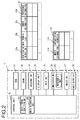
- FIG. 2 is a block diagram schematically showing a configuration of the in-vehicle terminal 3.
- the in-vehicle terminal 3 includes a control unit 30, a ROM 31, a DRAM 32, an occupant database (DB) 33, a display unit 34, an input unit 35, a communication unit 36, a music DB 37, and an audio output unit 38.
- the control unit 30 is composed of a CPU (not shown) and its peripheral circuits.
- the ROM 31 is a nonvolatile storage medium. A predetermined control program has been stored in advance in the ROM 31.
- the control unit 30 controls the in-vehicle terminal 3 by reading the control program from the ROM 31 and executing the control program.
- the DRAM 32 is a temporary storage medium. The control unit 30 utilizes the DRAM 32 as a working storage area.
- the occupant DB 33 is a database that stores occupants who own portable information terminals. As schematically shown in FIG. 2 , the occupant DB 33 stores one or more identification information 33a, main terminal flags 33b, owner information 33c, and preference information 33d in such a manner that they are associated to one another.
- the identification information 33a is information indicating a Bluetooth (TM) Device Address (BD ADDR) of a portable information terminal.
- BD ADDR Device Address
- the main terminal flag 33b is information indicating whether the respective portable information terminal is the main terminal 4 or not.
- the owner information 33c is information indicating an owner of the respective portable information terminal.
- the preference information 33d is information indicating a music genre matched with the preference of the owner of the respective portable information terminal.
- the display unit 34 is a display device such as a liquid crystal monitor, for example.
- the control unit 30 displays a variety of images and texts on the display unit 34.
- the input unit 35 is an input device such as a touch panel, for example.
- the communication unit 36 wirelessly communicates with the main terminal 4 and the portable information terminals 5.
- the communication unit 36 is a communication module that complies with the Bluetooth standard, for example.
- the communication unit 36 has a measurement unit 361.
- the measurement unit 361 measures electric field strengths of radio waves sent out from the main terminal 4 and the portable information terminals 5 located in the vicinity thereof, before the wireless communication.
- the music DB 37 is a database in which a plurality of music data are stored. As schematically shown in FIG. 2 , the music DB 37 stores a plurality of music information 37a and category information 37b in such a manner that they are associated with each other.
- the music information 37a is digital music data.
- the category information 37b is information indicating genres to which the respective music information 37a belongs. Each music information 37a belongs to one or more genres.
- the control unit 30 has a main terminal identifying unit 301 and a music reproducing unit 302.
- the main terminal identifying unit 301 and the music reproducing unit 302 are functional units in the form of software whose functions are achieved by the control unit 30 executing the control program. It will be noted that each of these functional units may be composed of electronic circuits.
- the main terminal identifying unit 301 identifies the main terminal 4 from portable information terminals located in the vicinity thereof (as described hereinafter in detail).
- the music reproducing unit 302 outputs audio signals produced from the music information 37a to the audio output unit 38.
- the audio output unit 38 is connected to a speaker (not shown) or the like. In other words, the music reproducing unit 302 reproduces the music information 37a by means of the speaker (not shown) or the like.
- FIG. 3 is a block diagram schematically showing a configuration of the main terminal 4.
- the main terminal 4 includes a control unit 40, a ROM 41, a DRAM 42, a display unit 44, an input unit 45, and a communication unit 46.
- the control unit 40 is composed of a CPU (not shown) and its peripheral circuits.
- the ROM 41 is an nonvolatile storage medium. A predetermined control program has been stored in advance in the ROM 41.
- the control unit 40 controls the main terminal 4 by reading the control program from the ROM 41 and executing the control program.
- the DRAM 42 is a temporary storage medium. The control unit 40 utilizes the DRAM 42 as a working storage area.
- the display unit 44 is a display device such as a liquid crystal monitor, for example.
- the control unit 40 displays a variety of images and texts on the display unit 44.
- the input unit 45 is an input device such as a touch panel, for example.
- the communication unit 46 wirelessly communicates with the in-vehicle terminal 3 and the portable information terminals 5.
- the communication unit 46 is a communication module that complies with the Bluetooth standard, for example.
- the communication unit 46 has a measurement unit 461.
- the measurement unit 461 measures electric field strengths of radio waves sent out from the in-vehicle terminal 3 and the portable information terminals 5 located in the vicinity thereof, before the wireless communication.
- the control unit 40 has a position determining unit 401.
- the position determining unit 401 is a functional unit in the form of software whose function is achieved by the control unit 40 executing the control program.
- the position determining unit 401 determines a positional relationship between the in-vehicle terminal 3, the main terminal 4, and the portable information terminals 5 (as described hereinafter in detail).
- the occupant DB 33 stores information about an owner for each portable information terminal (owner information 33c) and information about a preference of the respective owner (preference information 33d).
- owner information 33c information about an owner for each portable information terminal
- preference information 33d information about a preference of the respective owner
- the information about the main terminal 4 is stored at the initial setting time of the in-vehicle system 1, for example. If the Bluetooth is used as a communication scheme, the initial setting is a so-called pairing process.
- the information about the portable information terminals 5 other than the main terminal 4 is manually registered by the driver who carries the main terminal 4. A specific registration procedure will be described below.
- the position determining unit 401 of the main terminal 4 determines positions of the portable information terminals 5 located in the vicinity thereof (as described hereinafter in detail).
- the control unit 40 of the main terminal 4 transmits the identification information 33a of the portable information terminals 5 located in the vicinity thereof and the positions of the portable information terminals 5 determined by the position determining unit 401 to the in-vehicle terminal 3.
- the control unit 30 of the in-vehicle terminal 3 determines whether the identification information 33a is included in the occupant DB 33 or not. In other words, the control unit 30 determines whether the portable information terminal 5 identified by the identification information 33a has already been registered or not. On the basis of this determination result, the control unit 30 displays the position of the portable information terminal 5 on the display unit 34.
- FIG. 4 is an example of a screen image that displays the positions of the portable information terminals 5.
- the control unit 30 displays an image 60 schematically representing a vehicle interior of the vehicle 2 on the display unit 34.
- the control unit 30 displays registered-terminal icons 61 indicating positions of the main terminal 4 and portable information terminals 5 that have already been registered in the occupant DB 33, and unregistered-terminal icons 62 indicating portable information terminals 5 that has not been registered in the occupant DB 33, in such a manner that they are superimposed on the image 60.
- the main terminal 4 and the registered portable information terminals 5 may be displayed by different icons to each other.
- the driver can perform a registration operation of registering the portable information terminal 5 corresponding to the unregistered-terminal icon 62 to the occupant DB 33.
- the driver touches the unregistered-terminal icon 62 via the input unit 35, which is a touch panel.
- the control unit 30 displays an input box or the like for input of information about the portable information terminal 5 corresponding to the unregistered-terminal icon 62 touched by the driver, on the display unit 34.
- the driver inputs the owner information 33c and the preference information 33d in the displayed input box or the like.
- the control unit 30 associates the identification information 33a of the portable information terminal 5 corresponding to the unregistered-terminal icon 62 touched by the driver with the owner information 33c and the preference information 33d which are here input, and then stores (registers) the information in the occupant DB 33. It will be noted that since the portable information terminal 5 that is newly registered here is not the main terminal 4, the control unit 30 stores the portable information terminal 5 with its main terminal flag 33b of 0 in the occupant DB 33.
- control unit 30 changes the unregistered-terminal icon 62 that has been displayed on the display unit 34 into an registered-terminal icon 61.
- the music reproducing unit 302 selects and reproduces music information 37a matched with the preferences of the occupants of the vehicle 2 from a large number of music information 37a stored in the music DB 37. For example, when the driver instructs the in-vehicle terminal 3 to reproduce music via the input unit 35 or the like, the music reproducing unit 302 executes a music reproducing process. The music reproducing process will now be described in detail.
- the music reproducing unit 302 retrieves the identification information 33a of the main terminal 4 and the portable information terminals 5 that are present in the vehicle 2, from the occupant DB 33. If the identification information 33a has been registered in the occupant DB 33, the music reproducing unit 302 reads out corresponding preference information 33d from the occupant DB 33.
- the music reproducing unit 302 retrieves music information 37a associated with category information 37b that includes at least one of genres included in the read-out preference information 33d, from the music DB 37. For example, if the read-out preference information 33d includes two genres, "pop" and "rock", the music reproducing unit 302 retrieves music information 37a having its corresponding category information 37b that includes at least one of "pop" and "rock".
- the music reproducing unit 302 retrieves the music information 37a from the preference information 33d on the basis of an union of genres included in the plurality of preference information 33d. In other words, the music reproducing unit 302 retrieves music information 37a associated with category information 37b that includes at least one of genres included in either one of the plurality of preference information 33d.
- the music reproducing unit 302 selects and reproduces one arbitrary music information 37a, among the music information 37a included in the retrieval result. It will be noted that if the identification information 33a of a portable information terminal 5 that is present in the vehicle 2 is not included in the occupant DB 33, the music reproducing unit 302 ignores this portable information terminal 5.
- the music reproducing unit 302 selects and reproduces the music information 37a belonging to the genres matched with the preferences of the occupants from a large number of music information 37a.
- a method of determining a position of a portable information terminal 5 by means of the in-vehicle system 1 will be described.
- the in-vehicle terminal 3 and the main terminal 4 execute a terminal position determining process as described below in detail.
- the control unit 30 of the in-vehicle terminal 3 displays the position of the portable information terminal 5 determined by the terminal position determining process on the display unit 34.
- the terminal position determining process is started by the control unit 30 of the in-vehicle terminal 3.
- the control unit 30 causes the communication unit 36 to detect portable information terminals located in the vicinity thereof.
- the communication unit 36 performs a Bluetooth inquiry operation, for example, and sends out radio signals (inquiry signals) for causing portable information terminals located in the vicinity thereof to provide information about themselves.
- radio signals inquiry signals
- the communication unit 36 of the in-vehicle terminal 3 receives the response signals sent out from each portable information terminals.
- the communication unit 36 obtains a list of portable information terminals that are present in the vicinity thereof, by listing the identification information 33a included in the received response signals.
- the measurement unit 361 measures electric field strengths of the response signals.
- the control unit 30 associates the electric field strengths measured by the measurement unit 361 with the list of portable information terminals obtained by the communication unit 36 (the list of the identification information 33a) and then keeps this information in the DRAM 32.
- the main terminal identifying unit 301 retrieves each identification information 33a kept in the DRAM 32, from the occupant DB 33. Thereby, the identification information 33a kept in the DRAM 32 is categorized into the identification information 33a that has already been registered in the occupant DB 33 and the (unregistered) identification information 33a that has not been registered in the occupant DB 33.
- the main terminal identifying unit 301 further categorizes the identification information 33a that has already been registered in the occupant DB 33 into the identification information 33a of the main terminal 4 and the identification information 33a of the portable information terminals 5 which are not the main terminal 4, by referring to the values of the main terminal flags 33b. In other words, the main terminal identifying unit 301 identifies the main terminal 4 among the portable information terminals. Namely, at this point of time, the portable information terminals present in the vicinity of the main terminal identifying unit 301 are categorized into the main terminal 4, the registered portable information terminals 5, and the unregistered portable information terminals 5.
- the control unit 30 establishes wireless communication with the main terminal 4.
- the control unit 30 transmits the electric field strength measured for the main terminal 4 which is kept in the DRAM 32 and the identification information 33a and electric field strengths of other portable information terminals 5 which are kept in the DRAM 32, via the established wireless communication to the main terminal 4.
- the control unit 40 of the main terminal 4 keeps these information received by the communication unit 46 in the DRAM 42 of the main terminal 4. At this point of time, the following information are kept in the DRAM 42 of the main terminal 4.
- the position determining unit 401 of the main terminal 4 determines a relative positional relationship between the in-vehicle terminal 3 and the main terminal 4 on the basis of the above-described information (1).
- the in-vehicle terminal 3, the main terminal 4, and the portable information terminals 5 are located in a plane that is parallel to a floor of the vehicle 2 and is at a predetermined height, and the positional relationship in this plane will be considered.
- positional relationships in a vertical direction of the in-vehicle terminal 3, the main terminal 4, and the portable information terminals 5 will not be taken into consideration.
- FIG. 5 is a schematic view explaining a method of determining the relative positional relationship between the in-vehicle terminal 3 and the main terminal 4.
- a two-dimensional coordinate system is established, wherein the right direction of the vehicle 2 is the +x direction and the rear direction of the vehicle 2 is the +y direction.
- the position of the in-vehicle terminal 3 will be set as an origin and represented by a coordinate (0, 0).
- the electric field strength of the radio signal attenuates in proportion to a distance. Therefore, the position determining unit 401 can determine a length L0 from the in-vehicle terminal 3 to the main terminal 4, from the above-described information (1).
- the main terminal 4 is located on a circumference of a circle 64 having a radius L0, with the coordinate (0, 0) being as its center.
- the position determining unit 401 considers that the main terminal 4 is present at a position apart from the origin (0, 0) by a predetermined distance LD in the rear direction of the vehicle 2.
- the predetermined distance LD is a distance that is determined on the basis of the position of a driver seat of the vehicle 2.
- the main terminal 4 should be located either at a coordinate (-xd, LD) or at a coordinate (xd, LD), as shown in FIG. 5 .
- the position determining unit 401 determines the coordinate (xd, LD) as the position of the main terminal 4. If the vehicle 2 is a left-hand-drive vehicle, the position determining unit 401 determines the coordinate (-xd, LD) as the position of the main terminal 4. In the following description, the coordinate of the main terminal 4 determined here will be represented by (Xd, Yd).
- the predetermined distance LD may be adjustable by the driver as desired.
- the predetermined distance LD may vary depending on the position of the driver seat.
- the predetermined distance LD may vary also depending on the posture of the driver or a position where the main terminal 4 is carried. Because the driver can adjust the predetermined distance LD depending on the above-described situations, it is possible to determine the position of the main terminal 4 with a higher accuracy.
- the position determining unit 401 determines the coordinate (Xd, Yd) of the main terminal 4 by means of the above-described process, with the coordinate of the in-vehicle terminal 3 being (0, 0). In other words, the position determining unit 401 determines the relative positional relationship between the in-vehicle terminal 3 and the main terminal 4. On the basis of the thus determined positional relationship, the position determining unit 401 then determines the position of each portable information terminal 5.
- the position determining unit 401 causes the communication unit 46 to detect portable information terminals 5 located in the vicinity thereof.
- the communication unit 36 performs a Bluetooth inquiry operation, for example, and sends out radio signals (inquiry signals) for causing portable information terminals 5 located in the vicinity thereof to provide information about themselves.
- radio signals inquiry signals
- the communication unit 46 of the main terminal 4 receives the response signals sent out from the portable information terminals 5.
- the communication unit 46 obtains a list of portable information terminals that are present in the vicinity thereof, by listing the identification information 33a included in the received response signals.
- the measurement unit 461 measures electric field strengths of the response signals.
- the control unit 40 further associates the electric field strengths measured by the measurement unit 461 with the above-described information (2), (4) received from the in-vehicle terminal 3 and then keeps this information in the DRAM 42.
- the following information (6) to (8) are kept in the DRAM 42 of the main terminal 4, in addition to the information (1) to (5).
- the position determining unit 401 determines the position of each registered portable information terminal 5. Similarly, on the basis of the above-described information (5), (6) and (8), the position determining unit 401 then determines the position of each unregistered portable information terminal 5.
- FIG. 6 is a schematic view explaining a method of determining a position of a portable information terminal 5.
- the electric field strength of the radio signal attenuates in proportion to a distance. Therefore, the position determining unit 401 can determine a length L1 from the in-vehicle terminal 3 to the portable information terminal 5, from the above-described information (3) or (5).
- the portable information terminal 5 is located on a circumference of a circle 65 having a radius L1, with the coordinate (0, 0) being as its center. Further, the position determining unit 401 can determine a length L2 from the main terminal 4 to the portable information terminal 5, from the above-described information (7) or (8).
- the portable information terminal 5 is located on a circumference of a circle 66 having a radius L2, with the coordinate (Xd, Yd) being as its center. Thus, it is found that the portable information terminal 5 is located at either of intersection points P1, P2 of two circles 65, 66.
- the position determining unit 401 determines at which intersection point P1 or P2 the portable information terminal 5 is present, on the basis of a predetermined effective range 67.
- the predetermined effective range 67 is a range in which the occupants may be present, wherein the range is determined on the basis of dimensions of the vehicle interior of the vehicle 2. Considering the circle 65 having a radius L1 and the circle 66 having a radius L2, one of two intersection points P1, P2 of the circles 65, 66 may be located outside of the vehicle interior of the vehicle 2 as illustrated in FIG. 6 .
- the position determining unit 401 excludes the intersection point P1 among the two intersection points P1, P2 that is out of the effective range 67, from candidates for the position of the portable information terminal 5. In the example of FIG. 6 , the position determining unit 401 determines the intersection point P2 that is located within the effective range 67 as the position of the portable information terminal 5.
- the position determining unit 401 determines the position of each portable information terminal 5 that is present in the vicinity thereof, in accordance with the above-described procedure.
- the control unit 40 transmits positional information indicating the position of the main terminal 4 and positional information indicating the positions of portable information terminals 5, in association with the identification information 33a, to the in-vehicle terminal 3.
- the control unit 30 of the in-vehicle terminal 3 displays the positions of the main terminal 4 and the portable information terminals 5 on the display unit 34, on the basis of the received positional information.
- the position determining unit 401 handles the two points as the position of the portable information terminal 5.
- the control unit 30 displays the unregistered-terminal icons 62 or the registered-terminal icons 61 at both positions.
- the position determining unit 401 determines that the portable information terminal 5 is located outside of the vehicle interior and ignores this portable information terminal 5.
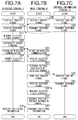
- FIGS. 7A to 7C are flowcharts of the terminal position determining process.
- FIG. 7A shows a process executed by the in-vehicle terminal 3.
- FIG. 7B shows a process executed by the main terminal 4.
- FIG. 7C shows a process executed by the portable information terminal 5.
- step S105 the communication unit 36 sends out inquiry signals to the main terminal 4 and the portable information terminals 5 located in the vicinity thereof.
- step S110 the communication unit 36 receives response signals sent out from the main terminal 4 and the portable information terminals 5 located in the vicinity thereof.
- step S115 the measurement unit 361 measures an electric field strength for each received response signal.
- step S120 the control unit 30 looks up the occupant DB 33 and categorizes sources of the response signals into the main terminal 4, the registered portable information terminals 5, and the unregistered portable information terminals 5.
- step S125 the communication unit 36 establishes wireless communication with the main terminal 4.
- step S130 the communication unit 36 transmits the identification information 33a included in the response signals received in step S110 and the electric field strength for each terminal measured in step S 115 to the main terminal 4.
- step S160 the communication unit 36 receives positional information for each terminal transmitted from the main terminal 4.
- control program executed by the control unit 30 of the in-vehicle terminal 3 includes: a measuring step of measuring electric field strengths of radio waves for wireless communication emitted from portable information terminals located in the vicinity thereof; a main terminal identifying step of identifying a main terminal 4 among the portable information terminals; and a communicating step of establishing wireless communication with the identified main terminal 4 and transmitting electric field strengths for other portable information terminals 5 than the main terminal 4 measured by the measuring step, via the wireless communication to the main terminal 4.
- step S205 the communication unit 46 receives the inquiry signal sent out from the in-vehicle terminal 3.
- step S210 the communication unit 46 sends out a response signal including the identification information 33a of the main terminal 4 to the in-vehicle terminal 3.
- step S225 the communication unit 46 establishes wireless communication with the in-vehicle terminal 3.
- step S230 the communication unit 46 receives sets of the identification information 33a and the electric field strengths of the portable information terminals 5, which are transmitted from the in-vehicle terminal 3.
- step S235 the position determining unit 401 determines a relative positional relationship between the in-vehicle terminal 3 and the main terminal 4, on the basis of the electric field strength of the response signal sent out from the main terminal 4, as measured by the in-vehicle terminal 3. In other words, the position determining unit 401 determines the coordinate (Xd, Yd) of the main terminal 4, with the coordinate of the in-vehicle terminal 3 being (0, 0).
- the communication unit 46 sends out inquiry signals to the portable information terminals 5 located in the vicinity thereof.
- step S245 the communication unit 46 receives response signals sent out from the portable information terminals 5 located in the vicinity thereof.
- the measurement unit 461 measures an electric field strength for each received response signal.
- step S255 the position determining unit 401 determines the position of each portable information terminal 5, in accordance with the procedure explained in FIG. 6 .
- step S260 the communication unit 46 transmits positional information indicating the position of the identified main terminal 4 and the positions of the portable information terminals 5 to the in-vehicle terminal 3.
- step S305 the communication unit of the portable information terminal 5 receives the inquiry signal sent out from the in-vehicle terminal 3.
- the communication unit of the portable information terminal 5 sends out a response signal including the identification information 33a of the portable information terminal 5 to the in-vehicle terminal 3.
- step S340 the communication unit of the portable information terminal 5 receives the inquiry signal sent out from the main terminal 4.
- step S345 the communication unit of the portable information terminal 5 sends out a response signal including the identification information 33a of the portable information terminal 5 to the main terminal 4.
- the main terminal 4 has the position determining unit 401 that determines the positions of the portable information terminals 5. In other words, the main terminal 4 determines the position of each portable information terminal 5. In a second embodiment described below, the in-vehicle terminal 1003 determines the position of each portable information terminal 5.
- FIG. 8 is a block diagram schematically showing a configuration of the in-vehicle terminal 1003.
- the in-vehicle terminal 1003 is different from the in-vehicle terminal 3 shown in FIG. 2 in that the control unit 30 has the position determining unit 401.
- FIG. 9 is a block diagram schematically showing a configuration of the main terminal 1004.
- the main terminal 1004 is different from the main terminal 4 shown in FIG. 3 in that the control unit 40 does not have any position determining unit.
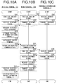
- FIGS. 10A to 10C are flowcharts of a terminal position determining process. It will be noted that the same processes as in the terminal position determining process ( FIGS. 7A to 7C ) according to the first embodiment are denoted by the same reference numerals as in the first embodiment.
- FIG. 10A shows a process executed by the in-vehicle terminal 1003.
- FIG. 10B shows a process executed by the main terminal 1004.
- FIG. 10C shows a process executed by the portable information terminal 5.
- step S105 the communication unit 36 sends out inquiry signals to the main terminal 4 and the portable information terminals 5 located in the vicinity thereof.
- step S110 the communication unit 36 receives response signals sent out from the main terminal 4 and the portable information terminals 5 located in the vicinity thereof.
- step S115 the measurement unit 361 measures an electric field strength for each received response signal. The electric field strength corresponding to each of the main terminal 1004 and the portable information terminals 5 measured here is kept by the DRAM 32.
- step S118 the position determining unit 401 determines a relative positional relationship between the in-vehicle terminal 1003 and the main terminal 1004, on the basis of the electric field strength of the response signal sent out from the main terminal 1004, as measured by the in-vehicle terminal 1003. In other words, the position determining unit 401 determines the coordinate (Xd, Yd) of the main terminal 1004, with the coordinate of the in-vehicle terminal 1003 being (0, 0).
- step S120 the control unit 30 looks up the occupant DB 33 and categorizes sources of the response signals into the main terminal 1004, the registered portable information terminals 5, and the unregistered portable information terminals 5.
- step S125 the communication unit 36 establishes wireless communication with the main terminal 1004.
- step S165 the communication unit 36 receives sets of the identification information 33a and the electric field strengths of the portable information terminals 5, which are transmitted from the main terminal 1004.
- step S170 the position determining unit 401 determines the position of each portable information terminal 5, in accordance with the procedure explained in FIG. 6 .
- the control program executed by the control unit 30 of the in-vehicle terminal 1003 includes: a measuring step of measuring electric field strengths of radio waves for wireless communication emitted from portable information terminals located in the vicinity thereof; a main terminal identifying step of identifying a main terminal 1004 among the portable information terminals; a keeping step of keeping electric field strengths for other portable information terminals 5 than the identified main terminal 1004 measured by the measuring step; and a communication step of establishing wireless communication with the main terminal 1004 and receiving the electric field strengths for other information terminals 5 measured by the main terminal 1004, from the main terminal 1004 via the wireless communication.
- step S205 the communication unit 46 receives the inquiry signal sent out from the in-vehicle terminal 1003.
- step S210 the communication unit 46 sends out a response signal including the identification information 33a of the main terminal 1004 to the in-vehicle terminal 1003.
- step S225 the communication unit 46 establishes wireless communication with the in-vehicle terminal 1003.
- step S240 the communication unit 46 sends out inquiry signals to portable information terminals 5 located in the vicinity thereof.
- step S245 the communication unit 46 receives the response signals sent out from the portable information terminals 5 located in the vicinity thereof.
- step S250 the measurement unit 461 measures an electric field strength for each received response signal.
- step S265 the communication unit 46 transmits the identification information 33a included in the response signals received in step S245 and the electric field strength for each terminal measured in step S250 to the in-vehicle terminal 1003.
- step S305 the communication unit of the portable information terminal 5 receives the inquiry signal sent out from the in-vehicle terminal 1003.
- step S310 the communication unit of the portable information terminal 5 sends out a response signal including the identification information 33a of the portable information terminal 5 to the in-vehicle terminal 1003.
- step S340 the communication unit of the portable information terminal 5 receives the inquiry signal sent out from the main terminal 1004.
- step S345 the communication unit of the portable information terminal 5 sends out a response signal including the identification information 33a of the portable information terminal 5 to the main terminal 1004.
- the positions of the portable information terminals 5 determined by the position determining unit 401 are used for display on the display unit 34.
- the positions of the portable information terminals 5 determined by the position determining unit 401 may be used for other purposes.
- the positional information may be used for preventing the occupants to leave the portable information terminals 5 behind in the vehicle 2 when they get off the vehicle 2, with an alarm or the like.
- air conditioning is turned to be active only in places where the portable information terminals 5 are present, while air conditioning is inactive in other places, so that an energy-saving air conditioning feature can be achieved.
- the music reproducing feature that provides music optimized for the occupants has been described.
- information about whether the occupant is sensitive to heat or cold has been stored in the occupant DB 33 as preference information 33d.
- the control unit 30 changes an air volume or temperature setting of an air conditioner in accordance with the preference information 33d, so that an air conditioning feature that provides air conditioning optimized for the occupants can be implemented.
- the position determining unit 401 may determine a positional relationship between the in-vehicle terminal 3 (or the in-vehicle terminal 1003; the same shall apply hereinafter) and the main terminal 4 (or the main terminal 1004; the same shall apply hereinafter), on the basis of the electric field strength of the radio signal emitted from the in-vehicle terminal 3, as measured by the main terminal 4.
- a personal computer 400 may be provided with the programs through a CD-ROM 404.
- the personal computer 400 has a connect function to a communication line 401.
- a computer 402, which is a server computer that provides the programs described above, may store them on a recording medium such as a hard disk 403.
- the communication line 401 is a communication line such as the Internet or a personal computer communication, or a leased line, etc.
- the computer 402 may read out the programs using the hard disk 403, send them to the personal computer 400 through the communication line 401.
- the programs may be embodied on a carrier wave as a data signal, and sent through the communication line 401.
- the programs can be provided as a computer-readable computer program product in a variety of forms such as recording medium, a carrier wave, etc.
- positions of occupants can be detected without adding any dedicated components.
Landscapes
- Engineering & Computer Science (AREA)
- Computer Networks & Wireless Communication (AREA)
- Signal Processing (AREA)
- Mechanical Engineering (AREA)
- Physics & Mathematics (AREA)
- Transportation (AREA)
- Aviation & Aerospace Engineering (AREA)
- Radar, Positioning & Navigation (AREA)
- Remote Sensing (AREA)
- General Physics & Mathematics (AREA)
- Mobile Radio Communication Systems (AREA)
- Traffic Control Systems (AREA)
- Quality & Reliability (AREA)
- Electromagnetism (AREA)
- Telephone Function (AREA)
Abstract
Description
- The disclosure of the following priority application is herein incorporated by reference:
Japanese Patent Application No. 2015-137691 filed July 9, 2015 - The present invention relates to an in-vehicle terminal and a program.
-
Japanese Laid-Open Patent Publication No. 2012-132821 - According to the device described in the above-described patent publication, positions of occupants cannot be detected, although it can be detected whether the occupants are present or not.
- An in-vehicle terminal according to a first aspect of the present invention, comprises: a measurement unit that measures electric field strengths of radio waves for wireless communication emitted from information terminals located in a vicinity thereof; a main terminal identifying unit that identifies a predetermined main terminal among the information terminals; and a communication unit that establishes wireless communication with the identified main terminal and transmits a first electric field strength for another information terminal than the main terminal measured by the measurement unit, via the wireless communication to the main terminal.
- According to a second aspect of the present invention, in the in-vehicle terminal according to the first aspect, it is preferable that the measurement unit measures an electric field strength of a radio wave emitted from the main terminal when the communication unit establishes the wireless communication.
- According to a third aspect of the present invention, in the in-vehicle terminal according to the second aspect, it is preferable that the communication unit transmits a second electric field strength for the main terminal measured by the measurement unit, via the wireless communication to the main terminal.
- According to a fourth aspect of the present invention, in the in-vehicle terminal according to the third aspect, it is preferable that the communication unit receives positional information of the other information terminal calculated by the main terminal, from the main terminal via the wireless communication.
- According to a fifth aspect of the present invention, the in-vehicle terminal according to the fourth aspect may further comprise: a display unit that displays a position of the other information terminal, based on the positional information of the other information terminal received by the communication unit.
- An in-vehicle terminal according to a sixth aspect of the present invention comprises: a measurement unit that measures electric field strengths of radio waves for wireless communication emitted from information terminals located in a vicinity thereof; a main terminal identifying unit that identifies a predetermined main terminal among the information terminals; a keeping unit that keeps a first electric field strength for another portable information terminal than the identified main terminal measured by the measurement unit; and a communication unit that establishes wireless communication with the main terminal and receives a second electric field strength for the other information terminal measured by the main terminal, from the main terminal via the wireless communication.
- According to a seventh aspect of the present invention, in the in-vehicle terminal according to the sixth aspect, it is preferable that the measurement unit measures an electric field strength of a radio wave emitted from the main terminal when the communication unit establishes the wireless communication.
- According to an eighth aspect of the present invention, in the in-vehicle terminal according to the seventh aspect, it is preferable that the keeping unit further keeps a third electric field strength for the main terminal measured by the measurement unit; and the in-vehicle terminal further comprises: a position determining unit that determines a positional relationship between the in-vehicle terminal and the main terminal based on the third electric field strength.
- According to a ninth aspect of the present invention, in the in-vehicle terminal according to the eighth aspect, it is preferable that the position determining unit further determines a position of the other information terminal based on the positional relationship, the first electric field strength, and the second electric field strength.
- According to a tenth aspect of the present invention, in the in-vehicle terminal according to the ninth aspect, it is preferable that if there are a plurality of candidates for the position of the other information terminal determined based on the positional relationship, the first electric field strength, and the second electric field strength, the position determining unit determines the position of the other information terminal by excluding candidates that are present out of a predetermined range.
- According to an 11th aspect of the present invention, the in-vehicle terminal according to the tenth aspect may further comprise: a display unit that displays the position of the other information terminal determined by the position determining unit.
- In a computer-readable computer program product having a program to be executed by a computer according to a 12th aspect of the present invention, the program comprises: a measuring step of measuring electric field strengths of radio waves for wireless communication emitted from information terminals located in a vicinity thereof; a main terminal identifying step of identifying a predetermined main terminal among the information terminals; and a communication step of establishing wireless communication with the identified main terminal and transmitting a first electric field strength for another information terminal than the main terminal measured in the measuring step, via the wireless communication to the main terminal.
- In a 13th aspect of the present invention, in the computer program product according to the 12th aspect, it is preferable that in the measuring step, an electric field strength of a radio wave emitted from the main terminal is measured when establishing the wireless communication.
- In a 14th aspect of the present invention, in the computer program product according to the 13th aspect, it is preferable that in the communication step, a second electric field strength for the main terminal measured by the measuring step is transmitted via the wireless communication to the main terminal, in addition to the first electric field strength.
- In a 15th aspect of the present invention, in the computer program product according to the 14th aspect, it is preferable that in the communication step, positional information of the other information terminal calculated by the main terminal is received from the main terminal via the wireless communication.
- In a 16th aspect of the present invention, in the computer program product according to the 15th aspect, it is preferable that the program further comprises a display step of displaying a position of the other information terminal on the display device, based on the positional information of the other information terminal received in the communication step.
- In a computer-readable computer program product having a program to be executed by a computer according to a 17th aspect of the present invention, the program comprises: a measuring step of measuring electric field strengths of radio waves for wireless communication emitted from information terminals located in a vicinity thereof; a main terminal identifying step of identifying a predetermined main terminal among the information terminals; a keeping step of keeping a first electric field strength for another portable information terminal than the identified main terminal measured in the measuring step; and a communication step of establishing wireless communication with the main terminal and receiving a second electric field strength for the other information terminal measured by the main terminal, from the main terminal via the wireless communication.
- According to an 18th aspect of the present invention, in the computer program product according to the 17th aspect, it is preferable that in the measuring step, an electric field strength of a radio wave emitted from the main terminal is measured when establishing the wireless communication.
- According to a 19th aspect of the present invention, in the computer program product according to the 18th aspect, it is preferable that in the keeping step, a third electric field strength for the main terminal measured by the measuring step is further kept; and the program further comprises a position determining step of determining a positional relationship between an in-vehicle terminal and the main terminal based on the third electric field strength.
- According to a 20th aspect of the present invention, in the computer program product according to the 19th aspect, it is preferable that in the position determining step, a position of the other information terminal is determined based on the positional relationship, the first electric field strength, and the second electric field strength.
- According to a 21 st aspect of the present invention, in the computer program product according to the 20th aspect, it is preferable that in the position determining step, if there are a plurality of candidates for the position of the other information terminal determined based on the positional relationship, the first electric field strength, and the second electric field strength, the position of the other information terminal is determined by excluding candidates that are present out of a predetermined range.
- According to a 22nd aspect of the present invention, in the computer program product according to the 21st aspect, it is preferable that the program further comprises a display step of displaying the position of the other information terminal determined in the position determining step on a display device.
- A method according to a 23rd aspect of the present invention, comprises: a measuring step of measuring electric field strengths of radio waves for wireless communication emitted from information terminals located in a vicinity thereof; a main terminal identifying step of identifying a predetermined main terminal among the information terminals; and a communication step of establishing wireless communication with the identified main terminal and transmitting a first electric field strength for another information terminal than the main terminal measured in the measuring step, via the wireless communication to the main terminal.
- A method according to a 24th aspect of the present invention, comprises: a measuring step of measuring electric field strengths of radio waves for wireless communication emitted from information terminals located in a vicinity thereof; a main terminal identifying step of identifying a predetermined main terminal among the information terminals; a keeping step of keeping a first electric field strength for another portable information terminal than the identified main terminal measured by the measuring step; and a communication step of establishing wireless communication with the main terminal and receiving a second electric field strength for the other information terminal measured by the main terminal, from the main terminal via the wireless communication.
-
-
FIG.. 1 is a block diagram schematically showing an in-vehicle system according to a first embodiment. -
FIG.. 2 is a block diagram schematically showing a configuration of an in-vehicle terminal. -
FIG.. 3 is a block diagram schematically showing a configuration of a main terminal. -
FIG.. 4 is an example of a screen that displays positions of portable information terminals. -
FIG.. 5 is a schematic view explaining a method of determining a relative positional relationship between the in-vehicle terminal and the main terminal. -
FIG.. 6 is a schematic view explaining a method of determining positions of the portable information terminals. -
FIG.s. 7A to 7C are flowcharts of a terminal position determining process. -
FIG. 8 is a block diagram schematically showing a configuration of the in-vehicle terminal. -
FIG. 9 is a block diagram schematically showing a configuration of the main terminal. -
FIGS. 10A to 10C are flowcharts of a terminal position determining process. -
FIG. 11 illustrate that the programs are provided through a recording medium or data signal. -
FIG. 1 is a block diagram schematically showing an in-vehicle system according to a first embodiment. The in-vehicle system 1 includes an in-vehicle terminal 3 mounted in avehicle 2, and aportable information terminal 4 that a driver of thevehicle 2 owns. Among occupants of thevehicle 2, occupants other than the driver will be referred to as passengers in the following description. - The in-
vehicle system 1 recognizes occupants who carry portable information terminals, by detecting the portable information terminals. The in-vehicle system 1 includes an occupant database (as described hereinafter) that associates portable information terminals with occupants. The in-vehicle system 1 retrieves the detected portable information terminals from the occupant database to identify corresponding occupants. - In the following description, the
portable information terminal 4 that the driver owns will be referred to as amain terminal 4 and distinguished fromportable information terminals 5 that passengers own. -
FIG. 2 is a block diagram schematically showing a configuration of the in-vehicle terminal 3. The in-vehicle terminal 3 includes acontrol unit 30, aROM 31, aDRAM 32, an occupant database (DB) 33, adisplay unit 34, aninput unit 35, acommunication unit 36, amusic DB 37, and anaudio output unit 38. - The
control unit 30 is composed of a CPU (not shown) and its peripheral circuits. TheROM 31 is a nonvolatile storage medium. A predetermined control program has been stored in advance in theROM 31. Thecontrol unit 30 controls the in-vehicle terminal 3 by reading the control program from theROM 31 and executing the control program. TheDRAM 32 is a temporary storage medium. Thecontrol unit 30 utilizes theDRAM 32 as a working storage area. - The occupant DB 33 is a database that stores occupants who own portable information terminals. As schematically shown in
FIG. 2 , theoccupant DB 33 stores one ormore identification information 33a, mainterminal flags 33b,owner information 33c, andpreference information 33d in such a manner that they are associated to one another. Theidentification information 33a is information indicating a Bluetooth (TM) Device Address (BD ADDR) of a portable information terminal. Here, theidentification information 33a is only required to be information indicating an unique identifier for each portable information terminal and may be different information from the BD_ADDR. The mainterminal flag 33b is information indicating whether the respective portable information terminal is themain terminal 4 or not. Theowner information 33c is information indicating an owner of the respective portable information terminal. Thepreference information 33d is information indicating a music genre matched with the preference of the owner of the respective portable information terminal. - The
display unit 34 is a display device such as a liquid crystal monitor, for example. Thecontrol unit 30 displays a variety of images and texts on thedisplay unit 34. Theinput unit 35 is an input device such as a touch panel, for example. Thecommunication unit 36 wirelessly communicates with themain terminal 4 and theportable information terminals 5. Thecommunication unit 36 is a communication module that complies with the Bluetooth standard, for example. Thecommunication unit 36 has ameasurement unit 361. Themeasurement unit 361 measures electric field strengths of radio waves sent out from themain terminal 4 and theportable information terminals 5 located in the vicinity thereof, before the wireless communication. - The
music DB 37 is a database in which a plurality of music data are stored. As schematically shown inFIG. 2 , themusic DB 37 stores a plurality ofmusic information 37a andcategory information 37b in such a manner that they are associated with each other. Themusic information 37a is digital music data. Thecategory information 37b is information indicating genres to which therespective music information 37a belongs. Eachmusic information 37a belongs to one or more genres. - The
control unit 30 has a mainterminal identifying unit 301 and amusic reproducing unit 302. The mainterminal identifying unit 301 and themusic reproducing unit 302 are functional units in the form of software whose functions are achieved by thecontrol unit 30 executing the control program. It will be noted that each of these functional units may be composed of electronic circuits. - The main
terminal identifying unit 301 identifies themain terminal 4 from portable information terminals located in the vicinity thereof (as described hereinafter in detail). Themusic reproducing unit 302 outputs audio signals produced from themusic information 37a to theaudio output unit 38. Theaudio output unit 38 is connected to a speaker (not shown) or the like. In other words, themusic reproducing unit 302 reproduces themusic information 37a by means of the speaker (not shown) or the like. -
FIG. 3 is a block diagram schematically showing a configuration of themain terminal 4. Themain terminal 4 includes acontrol unit 40, aROM 41, aDRAM 42, adisplay unit 44, aninput unit 45, and acommunication unit 46. - The
control unit 40 is composed of a CPU (not shown) and its peripheral circuits. TheROM 41 is an nonvolatile storage medium. A predetermined control program has been stored in advance in theROM 41. Thecontrol unit 40 controls themain terminal 4 by reading the control program from theROM 41 and executing the control program. TheDRAM 42 is a temporary storage medium. Thecontrol unit 40 utilizes theDRAM 42 as a working storage area. - The
display unit 44 is a display device such as a liquid crystal monitor, for example. Thecontrol unit 40 displays a variety of images and texts on thedisplay unit 44. Theinput unit 45 is an input device such as a touch panel, for example. Thecommunication unit 46 wirelessly communicates with the in-vehicle terminal 3 and theportable information terminals 5. Thecommunication unit 46 is a communication module that complies with the Bluetooth standard, for example. Thecommunication unit 46 has ameasurement unit 461. Themeasurement unit 461 measures electric field strengths of radio waves sent out from the in-vehicle terminal 3 and theportable information terminals 5 located in the vicinity thereof, before the wireless communication. - The
control unit 40 has aposition determining unit 401. Theposition determining unit 401 is a functional unit in the form of software whose function is achieved by thecontrol unit 40 executing the control program. Theposition determining unit 401 determines a positional relationship between the in-vehicle terminal 3, themain terminal 4, and the portable information terminals 5 (as described hereinafter in detail). - As described above, the
occupant DB 33 stores information about an owner for each portable information terminal (owner information 33c) and information about a preference of the respective owner (preference information 33d). First, the information about themain terminal 4 is stored at the initial setting time of the in-vehicle system 1, for example. If the Bluetooth is used as a communication scheme, the initial setting is a so-called pairing process. The information about theportable information terminals 5 other than themain terminal 4 is manually registered by the driver who carries themain terminal 4. A specific registration procedure will be described below. - At a predetermined timing, such as when the in-
vehicle terminal 3 is powered on, theposition determining unit 401 of themain terminal 4 determines positions of theportable information terminals 5 located in the vicinity thereof (as described hereinafter in detail). Thecontrol unit 40 of themain terminal 4 transmits theidentification information 33a of theportable information terminals 5 located in the vicinity thereof and the positions of theportable information terminals 5 determined by theposition determining unit 401 to the in-vehicle terminal 3. - For each received
identification information 33a, thecontrol unit 30 of the in-vehicle terminal 3 determines whether theidentification information 33a is included in theoccupant DB 33 or not. In other words, thecontrol unit 30 determines whether theportable information terminal 5 identified by theidentification information 33a has already been registered or not. On the basis of this determination result, thecontrol unit 30 displays the position of theportable information terminal 5 on thedisplay unit 34. -
FIG. 4 is an example of a screen image that displays the positions of theportable information terminals 5. Thecontrol unit 30 displays animage 60 schematically representing a vehicle interior of thevehicle 2 on thedisplay unit 34. Thecontrol unit 30 displays registered-terminal icons 61 indicating positions of themain terminal 4 andportable information terminals 5 that have already been registered in theoccupant DB 33, and unregistered-terminal icons 62 indicatingportable information terminals 5 that has not been registered in theoccupant DB 33, in such a manner that they are superimposed on theimage 60. It will be noted that themain terminal 4 and the registeredportable information terminals 5 may be displayed by different icons to each other. - For the unregistered-
terminal icon 62 displayed on thedisplay unit 34, the driver can perform a registration operation of registering theportable information terminal 5 corresponding to the unregistered-terminal icon 62 to theoccupant DB 33. For example, the driver touches the unregistered-terminal icon 62 via theinput unit 35, which is a touch panel. In response to this operation, thecontrol unit 30 displays an input box or the like for input of information about theportable information terminal 5 corresponding to the unregistered-terminal icon 62 touched by the driver, on thedisplay unit 34. - The driver inputs the
owner information 33c and thepreference information 33d in the displayed input box or the like. Thecontrol unit 30 associates theidentification information 33a of theportable information terminal 5 corresponding to the unregistered-terminal icon 62 touched by the driver with theowner information 33c and thepreference information 33d which are here input, and then stores (registers) the information in theoccupant DB 33. It will be noted that since theportable information terminal 5 that is newly registered here is not themain terminal 4, thecontrol unit 30 stores theportable information terminal 5 with its mainterminal flag 33b of 0 in theoccupant DB 33. - After the registration is completed, the
control unit 30 changes the unregistered-terminal icon 62 that has been displayed on thedisplay unit 34 into an registered-terminal icon 61. - A music reproducing feature that the in-
vehicle system 1 has will be described. Themusic reproducing unit 302 selects and reproducesmusic information 37a matched with the preferences of the occupants of thevehicle 2 from a large number ofmusic information 37a stored in themusic DB 37. For example, when the driver instructs the in-vehicle terminal 3 to reproduce music via theinput unit 35 or the like, themusic reproducing unit 302 executes a music reproducing process. The music reproducing process will now be described in detail. - The
music reproducing unit 302 retrieves theidentification information 33a of themain terminal 4 and theportable information terminals 5 that are present in thevehicle 2, from theoccupant DB 33. If theidentification information 33a has been registered in theoccupant DB 33, themusic reproducing unit 302 reads out correspondingpreference information 33d from theoccupant DB 33. - The
music reproducing unit 302 retrievesmusic information 37a associated withcategory information 37b that includes at least one of genres included in the read-outpreference information 33d, from themusic DB 37. For example, if the read-outpreference information 33d includes two genres, "pop" and "rock", themusic reproducing unit 302 retrievesmusic information 37a having its correspondingcategory information 37b that includes at least one of "pop" and "rock". - It will be noted that if a plurality of
preference information 33d are read out from theoccupant DB 33, themusic reproducing unit 302 retrieves themusic information 37a from thepreference information 33d on the basis of an union of genres included in the plurality ofpreference information 33d. In other words, themusic reproducing unit 302 retrievesmusic information 37a associated withcategory information 37b that includes at least one of genres included in either one of the plurality ofpreference information 33d. - The
music reproducing unit 302 selects and reproduces onearbitrary music information 37a, among themusic information 37a included in the retrieval result. It will be noted that if theidentification information 33a of aportable information terminal 5 that is present in thevehicle 2 is not included in theoccupant DB 33, themusic reproducing unit 302 ignores thisportable information terminal 5. - In the way described above, the
music reproducing unit 302 selects and reproduces themusic information 37a belonging to the genres matched with the preferences of the occupants from a large number ofmusic information 37a. - A method of determining a position of a
portable information terminal 5 by means of the in-vehicle system 1 will be described. At a predetermined timing, such as when the in-vehicle terminal 3 is powered on, the in-vehicle terminal 3 and themain terminal 4 execute a terminal position determining process as described below in detail. As described before, when aportable information terminal 5 is registered into theoccupant DB 33, thecontrol unit 30 of the in-vehicle terminal 3 displays the position of theportable information terminal 5 determined by the terminal position determining process on thedisplay unit 34. - The terminal position determining process is started by the
control unit 30 of the in-vehicle terminal 3. Thecontrol unit 30 causes thecommunication unit 36 to detect portable information terminals located in the vicinity thereof. Thecommunication unit 36 performs a Bluetooth inquiry operation, for example, and sends out radio signals (inquiry signals) for causing portable information terminals located in the vicinity thereof to provide information about themselves. Once thecommunication unit 46 of themain terminal 4 and the communication units of theportable information terminals 5 have received the inquiry signals, they send out response signals including theirown identification information 33a and the like to the in-vehicle terminal 3. - The
communication unit 36 of the in-vehicle terminal 3 receives the response signals sent out from each portable information terminals. Thecommunication unit 36 obtains a list of portable information terminals that are present in the vicinity thereof, by listing theidentification information 33a included in the received response signals. When receiving the response signals, themeasurement unit 361 measures electric field strengths of the response signals. Thecontrol unit 30 associates the electric field strengths measured by themeasurement unit 361 with the list of portable information terminals obtained by the communication unit 36 (the list of theidentification information 33a) and then keeps this information in theDRAM 32. - The main
terminal identifying unit 301 retrieves eachidentification information 33a kept in theDRAM 32, from theoccupant DB 33. Thereby, theidentification information 33a kept in theDRAM 32 is categorized into theidentification information 33a that has already been registered in theoccupant DB 33 and the (unregistered)identification information 33a that has not been registered in theoccupant DB 33. The mainterminal identifying unit 301 further categorizes theidentification information 33a that has already been registered in theoccupant DB 33 into theidentification information 33a of themain terminal 4 and theidentification information 33a of theportable information terminals 5 which are not themain terminal 4, by referring to the values of the mainterminal flags 33b. In other words, the mainterminal identifying unit 301 identifies themain terminal 4 among the portable information terminals. Namely, at this point of time, the portable information terminals present in the vicinity of the mainterminal identifying unit 301 are categorized into themain terminal 4, the registeredportable information terminals 5, and the unregisteredportable information terminals 5. - The
control unit 30 establishes wireless communication with themain terminal 4. Thecontrol unit 30 transmits the electric field strength measured for themain terminal 4 which is kept in theDRAM 32 and theidentification information 33a and electric field strengths of otherportable information terminals 5 which are kept in theDRAM 32, via the established wireless communication to themain terminal 4. - The
control unit 40 of themain terminal 4 keeps these information received by thecommunication unit 46 in theDRAM 42 of themain terminal 4. At this point of time, the following information are kept in theDRAM 42 of themain terminal 4. - (1) the electric field strength of the radio signal emitted from the
main terminal 4, as measured by the in-vehicle terminal 3; - (2) the
identification information 33a of the registeredportable information terminals 5 detected by the in-vehicle terminal 3; - (3) the electric field strengths corresponding to the above-described information (2) detected by the in-
vehicle terminal 3; - (4) the
identification information 33a of the unregisteredportable information terminals 5 detected by the in-vehicle terminal 3; and - (5) the electric field strengths corresponding to the above-described information (4) detected by the in-
vehicle terminal 3. - First, the
position determining unit 401 of themain terminal 4 determines a relative positional relationship between the in-vehicle terminal 3 and themain terminal 4 on the basis of the above-described information (1). In the following description, it is assumed that the in-vehicle terminal 3, themain terminal 4, and theportable information terminals 5 are located in a plane that is parallel to a floor of thevehicle 2 and is at a predetermined height, and the positional relationship in this plane will be considered. In other words, in the following description, positional relationships in a vertical direction of the in-vehicle terminal 3, themain terminal 4, and theportable information terminals 5 will not be taken into consideration. -
FIG. 5 is a schematic view explaining a method of determining the relative positional relationship between the in-vehicle terminal 3 and themain terminal 4. InFIG. 5 , a two-dimensional coordinate system is established, wherein the right direction of thevehicle 2 is the +x direction and the rear direction of thevehicle 2 is the +y direction. For convenience of explanation, the position of the in-vehicle terminal 3 will be set as an origin and represented by a coordinate (0, 0). The electric field strength of the radio signal attenuates in proportion to a distance. Therefore, theposition determining unit 401 can determine a length L0 from the in-vehicle terminal 3 to themain terminal 4, from the above-described information (1). Themain terminal 4 is located on a circumference of acircle 64 having a radius L0, with the coordinate (0, 0) being as its center. Theposition determining unit 401 considers that themain terminal 4 is present at a position apart from the origin (0, 0) by a predetermined distance LD in the rear direction of thevehicle 2. The predetermined distance LD is a distance that is determined on the basis of the position of a driver seat of thevehicle 2. At this point of time, themain terminal 4 should be located either at a coordinate (-xd, LD) or at a coordinate (xd, LD), as shown inFIG. 5 . If thevehicle 2 is a right-hand-drive vehicle, theposition determining unit 401 determines the coordinate (xd, LD) as the position of themain terminal 4. If thevehicle 2 is a left-hand-drive vehicle, theposition determining unit 401 determines the coordinate (-xd, LD) as the position of themain terminal 4. In the following description, the coordinate of themain terminal 4 determined here will be represented by (Xd, Yd). - It will be noted that the predetermined distance LD may be adjustable by the driver as desired. For example, if the driver seat is movable in a front-rear direction, the predetermined distance LD may vary depending on the position of the driver seat. The predetermined distance LD may vary also depending on the posture of the driver or a position where the
main terminal 4 is carried. Because the driver can adjust the predetermined distance LD depending on the above-described situations, it is possible to determine the position of themain terminal 4 with a higher accuracy. - The
position determining unit 401 determines the coordinate (Xd, Yd) of themain terminal 4 by means of the above-described process, with the coordinate of the in-vehicle terminal 3 being (0, 0). In other words, theposition determining unit 401 determines the relative positional relationship between the in-vehicle terminal 3 and themain terminal 4. On the basis of the thus determined positional relationship, theposition determining unit 401 then determines the position of eachportable information terminal 5. - The
position determining unit 401 causes thecommunication unit 46 to detectportable information terminals 5 located in the vicinity thereof. Thecommunication unit 36 performs a Bluetooth inquiry operation, for example, and sends out radio signals (inquiry signals) for causingportable information terminals 5 located in the vicinity thereof to provide information about themselves. Once the communication units of theportable information terminals 5 have received the inquiry signals, they send out response signals including theirown identification information 33a and the like to themain terminal 4. - The
communication unit 46 of themain terminal 4 receives the response signals sent out from theportable information terminals 5. Thecommunication unit 46 obtains a list of portable information terminals that are present in the vicinity thereof, by listing theidentification information 33a included in the received response signals. When receiving the response signals, themeasurement unit 461 measures electric field strengths of the response signals. Thecontrol unit 40 further associates the electric field strengths measured by themeasurement unit 461 with the above-described information (2), (4) received from the in-vehicle terminal 3 and then keeps this information in theDRAM 42. - At this point of time, the following information (6) to (8) are kept in the
DRAM 42 of themain terminal 4, in addition to the information (1) to (5). - (6) the position (coordinate) of the
main terminal 4 determined by theposition determining unit 401; - (7) the electric field strengths corresponding to the above-described information (2) detected by the
main terminal 4; and - (8) the electric field strengths corresponding to the above-described information (4) detected by the
main terminal 4. - On the basis of the above-described information (3), (6) and (7), the
position determining unit 401 determines the position of each registeredportable information terminal 5. Similarly, on the basis of the above-described information (5), (6) and (8), theposition determining unit 401 then determines the position of each unregisteredportable information terminal 5. -
FIG. 6 is a schematic view explaining a method of determining a position of aportable information terminal 5. The electric field strength of the radio signal attenuates in proportion to a distance. Therefore, theposition determining unit 401 can determine a length L1 from the in-vehicle terminal 3 to theportable information terminal 5, from the above-described information (3) or (5). Theportable information terminal 5 is located on a circumference of acircle 65 having a radius L1, with the coordinate (0, 0) being as its center. Further, theposition determining unit 401 can determine a length L2 from themain terminal 4 to theportable information terminal 5, from the above-described information (7) or (8). Theportable information terminal 5 is located on a circumference of acircle 66 having a radius L2, with the coordinate (Xd, Yd) being as its center. Thus, it is found that theportable information terminal 5 is located at either of intersection points P1, P2 of twocircles - The
position determining unit 401 determines at which intersection point P1 or P2 theportable information terminal 5 is present, on the basis of a predeterminedeffective range 67. The predeterminedeffective range 67 is a range in which the occupants may be present, wherein the range is determined on the basis of dimensions of the vehicle interior of thevehicle 2. Considering thecircle 65 having a radius L1 and thecircle 66 having a radius L2, one of two intersection points P1, P2 of thecircles vehicle 2 as illustrated inFIG. 6 . Because the occupant is obviously in the vehicle interior of thevehicle 2, theposition determining unit 401 excludes the intersection point P1 among the two intersection points P1, P2 that is out of theeffective range 67, from candidates for the position of theportable information terminal 5. In the example ofFIG. 6 , theposition determining unit 401 determines the intersection point P2 that is located within theeffective range 67 as the position of theportable information terminal 5. - The
position determining unit 401 determines the position of eachportable information terminal 5 that is present in the vicinity thereof, in accordance with the above-described procedure. Thecontrol unit 40 transmits positional information indicating the position of themain terminal 4 and positional information indicating the positions ofportable information terminals 5, in association with theidentification information 33a, to the in-vehicle terminal 3. Thecontrol unit 30 of the in-vehicle terminal 3 displays the positions of themain terminal 4 and theportable information terminals 5 on thedisplay unit 34, on the basis of the received positional information. - It will be noted that if both of the two intersection points P1, P2 are within the
effective range 67, theposition determining unit 401 handles the two points as the position of theportable information terminal 5. Thecontrol unit 30 displays the unregistered-terminal icons 62 or the registered-terminal icons 61 at both positions. On the other hand, if both of the two intersection points P1, P2 are out of theeffective range 67, theposition determining unit 401 determines that theportable information terminal 5 is located outside of the vehicle interior and ignores thisportable information terminal 5. -
FIGS. 7A to 7C are flowcharts of the terminal position determining process.FIG. 7A shows a process executed by the in-vehicle terminal 3.FIG. 7B shows a process executed by themain terminal 4.FIG. 7C shows a process executed by theportable information terminal 5. - The process executed by the in-
vehicle terminal 3 as shown inFIG. 7A will be described. In step S105, thecommunication unit 36 sends out inquiry signals to themain terminal 4 and theportable information terminals 5 located in the vicinity thereof. In step S110, thecommunication unit 36 receives response signals sent out from themain terminal 4 and theportable information terminals 5 located in the vicinity thereof. In step S115, themeasurement unit 361 measures an electric field strength for each received response signal. In step S120, thecontrol unit 30 looks up theoccupant DB 33 and categorizes sources of the response signals into themain terminal 4, the registeredportable information terminals 5, and the unregisteredportable information terminals 5. In step S125, thecommunication unit 36 establishes wireless communication with themain terminal 4. In step S130, thecommunication unit 36 transmits theidentification information 33a included in the response signals received in step S110 and the electric field strength for each terminal measured in step S 115 to themain terminal 4. In step S160, thecommunication unit 36 receives positional information for each terminal transmitted from themain terminal 4. - Thus, the control program executed by the
control unit 30 of the in-vehicle terminal 3 includes: a measuring step of measuring electric field strengths of radio waves for wireless communication emitted from portable information terminals located in the vicinity thereof; a main terminal identifying step of identifying amain terminal 4 among the portable information terminals; and a communicating step of establishing wireless communication with the identifiedmain terminal 4 and transmitting electric field strengths for otherportable information terminals 5 than themain terminal 4 measured by the measuring step, via the wireless communication to themain terminal 4. - The process executed by the
main terminal 4 as shown inFIG. 7B will be described. In step S205, thecommunication unit 46 receives the inquiry signal sent out from the in-vehicle terminal 3. In step S210, thecommunication unit 46 sends out a response signal including theidentification information 33a of themain terminal 4 to the in-vehicle terminal 3. In step S225, thecommunication unit 46 establishes wireless communication with the in-vehicle terminal 3. In step S230, thecommunication unit 46 receives sets of theidentification information 33a and the electric field strengths of theportable information terminals 5, which are transmitted from the in-vehicle terminal 3. In step S235, theposition determining unit 401 determines a relative positional relationship between the in-vehicle terminal 3 and themain terminal 4, on the basis of the electric field strength of the response signal sent out from themain terminal 4, as measured by the in-vehicle terminal 3. In other words, theposition determining unit 401 determines the coordinate (Xd, Yd) of themain terminal 4, with the coordinate of the in-vehicle terminal 3 being (0, 0). In step S240, thecommunication unit 46 sends out inquiry signals to theportable information terminals 5 located in the vicinity thereof. In step S245, thecommunication unit 46 receives response signals sent out from theportable information terminals 5 located in the vicinity thereof. In step S250, themeasurement unit 461 measures an electric field strength for each received response signal. In step S255, theposition determining unit 401 determines the position of eachportable information terminal 5, in accordance with the procedure explained inFIG. 6 . In step S260, thecommunication unit 46 transmits positional information indicating the position of the identifiedmain terminal 4 and the positions of theportable information terminals 5 to the in-vehicle terminal 3. - The process executed by the
portable information terminal 5 as shown inFIG. 7C will be described. In step S305, the communication unit of theportable information terminal 5 receives the inquiry signal sent out from the in-vehicle terminal 3. In step S310, the communication unit of theportable information terminal 5 sends out a response signal including theidentification information 33a of theportable information terminal 5 to the in-vehicle terminal 3. In step S340, the communication unit of theportable information terminal 5 receives the inquiry signal sent out from themain terminal 4. In step S345, the communication unit of theportable information terminal 5 sends out a response signal including theidentification information 33a of theportable information terminal 5 to themain terminal 4. - According to the above-described embodiment, the following operational advantages can be obtained.
- (1) The
measurement unit 361 measures electric field strengths of radio waves for wireless communication emitted from portable information terminals located in the vicinity thereof. The mainterminal identifying unit 301 identifies themain terminal 4 among the portable information terminals. Thecommunication unit 36 establishes wireless communication with the identifiedmain terminal 4 and transmits electric field strengths (first electric field strengths) for otherportable information terminals 5 than themain terminal 4 measured by themeasurement unit 361, via the wireless communication to themain terminal 4. In this way, it is possible thatmain terminal 4 detects positions of the occupants, without adding any dedicated components to themain terminal 4. Furthermore, it is possible that the in-vehicle terminal 3 knows positions of the occupants, without adding any dedicated components to the in-vehicle terminal 3. - (2) The
measurement unit 361 measures the electric field strength of the radio wave emitted from themain terminal 4 when thecommunication unit 36 establishes the wireless communication with themain terminal 4. In this way, the electric field strength measured in the exchange of signals in the process of establishing the wireless can be used as it is, and it is thus not necessary to measure the electric field strength again, which results in an increase in the operating speed. Furthermore, because thecommunication unit 36 is configured to integrate themeasurement unit 361 therein, it is not necessary to additionally connect any special components for measuring the electric field strength to thecontrol unit 30 or the like, which results in a reduction in the number of parts. - (3) The
communication unit 36 transmits an electric field strength (second electric field strength) for themain terminal 4 measured by themeasurement unit 361, via the established wireless communication to themain terminal 4. In this way, the electric field strength measured in the exchange of signals in the process of establishing the wireless communication can be used as it is, and it is thus not necessary to measure the electric field strength again, which results in an increase in the operating speed. - (4) The
communication unit 36 receives positional information ofother information terminals 5 from themain terminal 4 via the wireless communication. In this way, it is possible to determine positions of theportable information terminals 5 and use the information for display on thedisplay unit 34 or the like. - (5) The
display unit 34 displays the positions of otherportable information terminals 5, on the basis of the positional information of otherportable information terminals 5 received by thecommunication unit 36. In this way, the registration of theportable information terminals 5 into the occupant DB is facilitated. This is because it can be easily determine who owns eachportable information terminal 5 on the basis of the position of theportable information terminal 5 displayed on thedisplay unit 34, even if a plurality of occupants carry theportable information terminals 5, for example. - In the first embodiment described above, the
main terminal 4 has theposition determining unit 401 that determines the positions of theportable information terminals 5. In other words, themain terminal 4 determines the position of eachportable information terminal 5. In a second embodiment described below, the in-vehicle terminal 1003 determines the position of eachportable information terminal 5. -
FIG. 8 is a block diagram schematically showing a configuration of the in-vehicle terminal 1003. The in-vehicle terminal 1003 is different from the in-vehicle terminal 3 shown inFIG. 2 in that thecontrol unit 30 has theposition determining unit 401. -
FIG. 9 is a block diagram schematically showing a configuration of themain terminal 1004. Themain terminal 1004 is different from themain terminal 4 shown inFIG. 3 in that thecontrol unit 40 does not have any position determining unit. -
FIGS. 10A to 10C are flowcharts of a terminal position determining process. It will be noted that the same processes as in the terminal position determining process (FIGS. 7A to 7C ) according to the first embodiment are denoted by the same reference numerals as in the first embodiment.FIG. 10A shows a process executed by the in-vehicle terminal 1003.FIG. 10B shows a process executed by themain terminal 1004.FIG. 10C shows a process executed by theportable information terminal 5. - The process executed by the in-
vehicle terminal 1003 as shown inFIG. 10A will be described. In step S105, thecommunication unit 36 sends out inquiry signals to themain terminal 4 and theportable information terminals 5 located in the vicinity thereof. In step S110, thecommunication unit 36 receives response signals sent out from themain terminal 4 and theportable information terminals 5 located in the vicinity thereof. In step S115, themeasurement unit 361 measures an electric field strength for each received response signal. The electric field strength corresponding to each of themain terminal 1004 and theportable information terminals 5 measured here is kept by theDRAM 32. In step S118, theposition determining unit 401 determines a relative positional relationship between the in-vehicle terminal 1003 and themain terminal 1004, on the basis of the electric field strength of the response signal sent out from themain terminal 1004, as measured by the in-vehicle terminal 1003. In other words, theposition determining unit 401 determines the coordinate (Xd, Yd) of themain terminal 1004, with the coordinate of the in-vehicle terminal 1003 being (0, 0). In step S120, thecontrol unit 30 looks up theoccupant DB 33 and categorizes sources of the response signals into themain terminal 1004, the registeredportable information terminals 5, and the unregisteredportable information terminals 5. In step S125, thecommunication unit 36 establishes wireless communication with themain terminal 1004. In step S165, thecommunication unit 36 receives sets of theidentification information 33a and the electric field strengths of theportable information terminals 5, which are transmitted from themain terminal 1004. In step S170, theposition determining unit 401 determines the position of eachportable information terminal 5, in accordance with the procedure explained inFIG. 6 . - Thus, the control program executed by the
control unit 30 of the in-vehicle terminal 1003 includes: a measuring step of measuring electric field strengths of radio waves for wireless communication emitted from portable information terminals located in the vicinity thereof; a main terminal identifying step of identifying amain terminal 1004 among the portable information terminals; a keeping step of keeping electric field strengths for otherportable information terminals 5 than the identified main terminal 1004 measured by the measuring step; and a communication step of establishing wireless communication with themain terminal 1004 and receiving the electric field strengths forother information terminals 5 measured by themain terminal 1004, from themain terminal 1004 via the wireless communication. - A process executed by the main terminal 1004 as shown in
FIG. 10B will be described. In step S205, thecommunication unit 46 receives the inquiry signal sent out from the in-vehicle terminal 1003. In step S210, thecommunication unit 46 sends out a response signal including theidentification information 33a of the main terminal 1004 to the in-vehicle terminal 1003. In step S225, thecommunication unit 46 establishes wireless communication with the in-vehicle terminal 1003. In step S240, thecommunication unit 46 sends out inquiry signals toportable information terminals 5 located in the vicinity thereof. In step S245, thecommunication unit 46 receives the response signals sent out from theportable information terminals 5 located in the vicinity thereof. In step S250, themeasurement unit 461 measures an electric field strength for each received response signal. In step S265, thecommunication unit 46 transmits theidentification information 33a included in the response signals received in step S245 and the electric field strength for each terminal measured in step S250 to the in-vehicle terminal 1003. - The process executed by the
portable information terminal 5 as shown inFIG. 10C will be described. In step S305, the communication unit of theportable information terminal 5 receives the inquiry signal sent out from the in-vehicle terminal 1003. In step S310, the communication unit of theportable information terminal 5 sends out a response signal including theidentification information 33a of theportable information terminal 5 to the in-vehicle terminal 1003. In step S340, the communication unit of theportable information terminal 5 receives the inquiry signal sent out from themain terminal 1004. In step S345, the communication unit of theportable information terminal 5 sends out a response signal including theidentification information 33a of theportable information terminal 5 to themain terminal 1004. - According to the above-described embodiment, the following operational advantages can be obtained.
- (6) The
measurement unit 361 measures electric field strengths of radio waves for wireless communication emitted from portable information terminals located in the vicinity thereof. The mainterminal identifying unit 301 identifies themain terminal 1004 among the portable information terminals. TheDRAM 32 serves as a keeping unit that keeps electric field strengths (first electric field strengths) for otherportable information terminals 5 than the identifiedmain terminal 4 measured by themeasurement unit 361. Thecommunication unit 36 establishes wireless communication with themain terminal 1004 and receives electric field strengths (second electric field strengths) for otherportable information terminals 5 measured by themain terminal 1004, from themain terminal 1004 via the wireless communication. In this way, it is possible that main terminal 1004 detects positions of the occupants, without adding any dedicated components to themain terminal 1004. Furthermore, it is possible that the in-vehicle terminal 1003 knows positions of the occupants, without adding any dedicated components to the in-vehicle terminal 1003. - (7) The
measurement unit 361 measures the electric field strength of the radio wave emitted from the main terminal 1004 when thecommunication unit 36 establishes the wireless communication with themain terminal 1004. In this way, the electric field strength measured in the exchange of signals in the process of establishing the wireless communication can be used as it is, and it is not necessary to measure the electric field strengths again, which results in an increase in the operating speed. Furthermore, because thecommunication unit 36 is configured to integrate themeasurement unit 361 therein, it is not necessary to separately connect any special components for measuring the electric field strength to thecontrol unit 30 or the like, which results in a reduction in the number of parts. - (8) The
DRAM 32 further keeps an electric field strength (third electric field strength) for the main terminal 1004 measured by themeasurement unit 361. Theposition determining unit 401 determines a relative positional relationship between the in-vehicle terminal 1003 and the main terminal 1004 on the basis of the third electric field strength. Because it is estimated that the position of themain terminal 1004 is within a limited range in the vicinity of the driver seat, the position of the main terminal 1004 which can be easily determined only with minimum required information is determined first, so that the positions of theportable information terminals 5 can then be easily determined. - (9) The
position determining unit 401 determines positions of otherportable information terminals 5 on the basis of the positional relationship between the in-vehicle terminal 1003 and themain terminal 1004 and on the basis of the first and second electric field strengths kept in theDRAM 32. In this way, it is possible to determine positions of theportable information terminals 5 with a high accuracy. - (10) If there are a plurality of candidates for the position of each of other
portable information terminals 5, theposition determining unit 401 determines the position of theportable information terminal 5 by excluding candidates that are present out of theeffective range 67. In this way, it is possible to determine positions of theportable information terminals 5 with a high accuracy. - (11) The
display unit 34 displays the positions of otherportable information terminals 5 determined by theposition determining unit 401. In this way, the registration of theportable information terminals 5 into the occupant DB is facilitated. - The following variations are also contemplated within the scope of the present invention and one or more of the variations may be combined with the above-described embodiments.
- In each embodiment described above, the positions of the
portable information terminals 5 determined by theposition determining unit 401 are used for display on thedisplay unit 34. The positions of theportable information terminals 5 determined by theposition determining unit 401 may be used for other purposes. For example, the positional information may be used for preventing the occupants to leave theportable information terminals 5 behind in thevehicle 2 when they get off thevehicle 2, with an alarm or the like. Moreover, air conditioning is turned to be active only in places where theportable information terminals 5 are present, while air conditioning is inactive in other places, so that an energy-saving air conditioning feature can be achieved. - In each embodiment described above, the music reproducing feature that provides music optimized for the occupants has been described. However, it is also possible to utilize the information of the occupants for other features. For example, information about whether the occupant is sensitive to heat or cold has been stored in the
occupant DB 33 aspreference information 33d. Thecontrol unit 30 changes an air volume or temperature setting of an air conditioner in accordance with thepreference information 33d, so that an air conditioning feature that provides air conditioning optimized for the occupants can be implemented. - The
position determining unit 401 may determine a positional relationship between the in-vehicle terminal 3 (or the in-vehicle terminal 1003; the same shall apply hereinafter) and the main terminal 4 (or themain terminal 1004; the same shall apply hereinafter), on the basis of the electric field strength of the radio signal emitted from the in-vehicle terminal 3, as measured by themain terminal 4. - In the case that the programs described above are applied to a personal computer, etc., the programs described above can be provided through a recording medium as a CD-ROM, or data signal as the Internet, as shown in
Fig. 11 . Apersonal computer 400 may be provided with the programs through a CD-ROM 404. Thepersonal computer 400 has a connect function to acommunication line 401. Acomputer 402, which is a server computer that provides the programs described above, may store them on a recording medium such as ahard disk 403. Thecommunication line 401 is a communication line such as the Internet or a personal computer communication, or a leased line, etc. Thecomputer 402 may read out the programs using thehard disk 403, send them to thepersonal computer 400 through thecommunication line 401. In other words, the programs may be embodied on a carrier wave as a data signal, and sent through thecommunication line 401. Thus, the programs can be provided as a computer-readable computer program product in a variety of forms such as recording medium, a carrier wave, etc. - According to the embodiments and variations of the present invention described above, positions of occupants can be detected without adding any dedicated components.
- Although a variety of embodiments and variations have been described above, the present invention is not limited to the contents of the embodiments and variations. Other aspects conceivable within the scope of the technical idea of the present invention are encompassed within the scope of the present invention.
Claims (13)
- An in-vehicle terminal (3), comprising:a measurement unit (36) that measures electric field strengths of radio waves for wireless communication emitted from information terminals located in a vicinity thereof;a main terminal (4) identifying unit that identifies a predetermined main terminal among the information terminals; anda communication unit (36) that establishes wireless communication with the identified main terminal (4) and transmits a first electric field strength for another information terminal (4) than the main terminal measured by the measurement unit, via the wireless communication to the main terminal (4).
- The in-vehicle terminal (3) according to claim 1, wherein:the measurement unit (36) measures an electric field strength of a radio wave emitted from the main terminal (4) when the communication unit (36) establishes the wireless communication.
- The in-vehicle terminal (3) according to claim 1 or 2, wherein:the communication unit (36) transmits a second electric field strength for the main terminal (4) measured by the measurement unit (36), via the wireless communication to the main terminal (4).
- The in-vehicle terminal (3) according to at least one of claims 1 to 3, wherein:the communication unit (36) receives positional information of the other information terminal calculated by the main terminal (4), from the main terminal (4) via the wireless communication.
- The in-vehicle terminal (3) according to claim 4, further comprising:a display unit that displays a position of the other information terminal, based on the positional information of the other information terminal received by the communication unit.
- An in-vehicle terminal (3), comprising:a measurement unit (36) that measures electric field strengths of radio waves for wireless communication emitted from information terminals located in a vicinity thereof;a main terminal (4) identifying unit that identifies a predetermined main terminal among the information terminals;a keeping unit that keeps a first electric field strength for another portable information terminal than the identified main terminal measured by the measurement unit; anda communication unit (36) that establishes wireless communication with the main terminal and receives a second electric field strength for the other information terminal measured by the main terminal, from the main terminal via the wireless communication.
- The in-vehicle terminal according to claim 6, wherein:the measurement unit (36) measures an electric field strength of a radio wave emitted from the main terminal when the communication unit establishes the wireless communication.
- The in-vehicle terminal (3) according to claim 6 or 7, wherein:the keeping unit further keeps a third electric field strength for the main terminal measured by the measurement unit; andthe in-vehicle terminal (3) further comprising:a position determining unit that determines a positional relationship between the in-vehicle terminal and the main terminal based on the third electric field strength.
- The in-vehicle terminal (3) according to claim 8, wherein:the position determining unit further determines a position of the other information terminal based on the positional relationship, the first electric field strength, and the second electric field strength.
- The in-vehicle terminal (3) according to claim 8 or 9, wherein:if there are a plurality of candidates for the position of the other information terminal determined based on the positional relationship, the first electric field strength, and the second electric field strength, the position determining unit determines the position of the other information terminal by excluding candidates that are present out of a predetermined range.
- The in-vehicle terminal (3) according to at least one of claims 8 to 10, further comprising:a display unit that displays the position of the other information terminal determined by the position determining unit.
- A method, comprising:a measuring step of measuring electric field strengths of radio waves for wireless communication emitted from information terminals located in a vicinity thereof;a main terminal (4) identifying step of identifying a predetermined main terminal among the information terminals; anda communication step of establishing wireless communication with the identified main terminal (4) and transmitting a first electric field strength for another information terminal than the main terminal measured in the measuring step, via the wireless communication to the main terminal (4).
- A method, comprising:a measuring step of measuring electric field strengths of radio waves for wireless communication emitted from information terminals located in a vicinity thereof;a main terminal (4) identifying step of identifying a predetermined main terminal among the information terminals;a keeping step of keeping a first electric field strength for another portable information terminal than the identified main terminal measured by the measuring step; anda communication step of establishing wireless communication with the main terminal (4) and receiving a second electric field strength for the other information terminal measured by the main terminal, from the main terminal via the wireless communication.
Applications Claiming Priority (1)
| Application Number | Priority Date | Filing Date | Title |
|---|---|---|---|
| JP2015137691A JP6539133B2 (en) | 2015-07-09 | 2015-07-09 | Vehicle-mounted terminal and program |
Publications (2)
| Publication Number | Publication Date |
|---|---|
| EP3115262A1 true EP3115262A1 (en) | 2017-01-11 |
| EP3115262B1 EP3115262B1 (en) | 2018-06-27 |
Family
ID=56408995
Family Applications (1)
| Application Number | Title | Priority Date | Filing Date |
|---|---|---|---|
| EP16178639.7A Active EP3115262B1 (en) | 2015-07-09 | 2016-07-08 | In-vehicle terminal |
Country Status (3)
| Country | Link |
|---|---|
| US (1) | US9813170B2 (en) |
| EP (1) | EP3115262B1 (en) |
| JP (1) | JP6539133B2 (en) |
Families Citing this family (4)
| Publication number | Priority date | Publication date | Assignee | Title |
|---|---|---|---|---|
| KR101967670B1 (en) * | 2012-06-15 | 2019-04-11 | 삼성전자주식회사 | Wireless communication method between terminals |
| EP3409034B1 (en) * | 2016-01-26 | 2024-04-03 | Beijing Didi Infinity Technology and Development Co., Ltd. | Systems and methods for monitoring on-route transportations |
| DK3577472T3 (en) * | 2017-02-06 | 2023-11-20 | Osmose Utilities Services Inc | APPARATUS AND METHOD FOR DETECTING DANGEROUS LIVE OBJECTS |
| US11300649B1 (en) * | 2017-06-24 | 2022-04-12 | Robotic Research Opco, Llc | Vehicle localization augmentation for dismounts |
Citations (8)
| Publication number | Priority date | Publication date | Assignee | Title |
|---|---|---|---|---|
| US20110195699A1 (en) * | 2009-10-31 | 2011-08-11 | Saied Tadayon | Controlling Mobile Device Functions |
| US20110237186A1 (en) * | 2010-03-16 | 2011-09-29 | Bayerische Motoren Werke Aktiengesellschaft | Motor Vehicle Configuration System |
| JP2012132821A (en) | 2010-12-22 | 2012-07-12 | Aisin Aw Co Ltd | On-vehicle control apparatus, on-vehicle control method and on-vehicle control program |
| US20130198802A1 (en) * | 2011-11-16 | 2013-08-01 | Flextronics Ap, Llc | On board vehicle media controller |
| DE102013201959A1 (en) * | 2013-02-06 | 2014-08-21 | Bayerische Motoren Werke Aktiengesellschaft | Control unit for matching configurable component e.g. vehicle-spreading component, of battery electric vehicle e.g. motor car, determines preference of user for configurable component based on identification and sitting position of user |
| WO2014160684A1 (en) * | 2013-03-26 | 2014-10-02 | Intel Corporation | Vehicular occupancy assessment |
| US20150057839A1 (en) * | 2013-08-26 | 2015-02-26 | Sherry S. Chang | Configuring user customizable operational features of a vehicle |
| US20150149042A1 (en) * | 2013-11-22 | 2015-05-28 | Qualcomm Incorporated | System and method for configuring an interior of a vehicle based on preferences provided with multiple mobile computing devices within the vehicle |
Family Cites Families (17)
| Publication number | Priority date | Publication date | Assignee | Title |
|---|---|---|---|---|
| JP2003248045A (en) | 2002-02-22 | 2003-09-05 | Alpine Electronics Inc | Apparatus for detecting location of occupant in cabin and on-board apparatus control system |
| JP2004297201A (en) | 2003-03-25 | 2004-10-21 | Fujitsu Ltd | Mobile phone search system and search method |
| WO2006001140A1 (en) | 2004-06-24 | 2006-01-05 | Matsushita Electric Industrial Co., Ltd. | Portable terminal, and radio quality display method, program, and system |
| MY163773A (en) * | 2005-09-13 | 2017-10-31 | Taiwan Semiconductor Mfg Co Ltd | Position determination of mobile stations in a wireless network |
| JPWO2007099743A1 (en) * | 2006-02-28 | 2009-07-16 | パナソニック株式会社 | Wireless communication apparatus and communication method thereof |
| CN101064911B (en) * | 2006-04-28 | 2012-08-22 | 上海贝尔阿尔卡特股份有限公司 | Switch control method, relay station and base station for wireless access system |
| JP2008042577A (en) * | 2006-08-07 | 2008-02-21 | Toyota Motor Corp | In-vehicle device |
| US20080077261A1 (en) * | 2006-08-29 | 2008-03-27 | Motorola, Inc. | Method and system for sharing an audio experience |
| KR101203461B1 (en) * | 2006-11-10 | 2012-11-21 | 삼성전자주식회사 | Routing method in multi-hop cellular system and the multi-hop cellular system |
| US8812065B2 (en) * | 2010-06-07 | 2014-08-19 | Ford Global Technologies, Llc | System and method for monitoring the location of a communication device in a vehicle based on signal strength |
| JP5866877B2 (en) | 2011-08-30 | 2016-02-24 | 大日本印刷株式会社 | Position detection system, terminal device, and position detection program |
| JP5861769B2 (en) * | 2012-03-30 | 2016-02-16 | 富士通株式会社 | Wireless communication method, node, and monitoring node |
| US8914043B2 (en) * | 2012-04-18 | 2014-12-16 | Google Inc. | Creating and sharing private location databases |
| EP4235603A3 (en) * | 2013-01-09 | 2024-01-24 | Paxgrid Telemetric Systems Inc. | Vehicle communications via wireless access vehicular environment |
| JP2014225209A (en) | 2013-05-17 | 2014-12-04 | 住友電工システムソリューション株式会社 | Communication system, communication adapter, and communication method |
| US9232495B2 (en) * | 2013-12-06 | 2016-01-05 | Location Labs, Inc. | Device association-based locating system and method |
| KR101568335B1 (en) * | 2014-11-26 | 2015-11-12 | 현대자동차주식회사 | Method and apparatus for providing bluetooth pairing in vehicle |
-
2015
- 2015-07-09 JP JP2015137691A patent/JP6539133B2/en active Active
-
2016
- 2016-07-08 US US15/205,409 patent/US9813170B2/en active Active
- 2016-07-08 EP EP16178639.7A patent/EP3115262B1/en active Active
Patent Citations (8)
| Publication number | Priority date | Publication date | Assignee | Title |
|---|---|---|---|---|
| US20110195699A1 (en) * | 2009-10-31 | 2011-08-11 | Saied Tadayon | Controlling Mobile Device Functions |
| US20110237186A1 (en) * | 2010-03-16 | 2011-09-29 | Bayerische Motoren Werke Aktiengesellschaft | Motor Vehicle Configuration System |
| JP2012132821A (en) | 2010-12-22 | 2012-07-12 | Aisin Aw Co Ltd | On-vehicle control apparatus, on-vehicle control method and on-vehicle control program |
| US20130198802A1 (en) * | 2011-11-16 | 2013-08-01 | Flextronics Ap, Llc | On board vehicle media controller |
| DE102013201959A1 (en) * | 2013-02-06 | 2014-08-21 | Bayerische Motoren Werke Aktiengesellschaft | Control unit for matching configurable component e.g. vehicle-spreading component, of battery electric vehicle e.g. motor car, determines preference of user for configurable component based on identification and sitting position of user |
| WO2014160684A1 (en) * | 2013-03-26 | 2014-10-02 | Intel Corporation | Vehicular occupancy assessment |
| US20150057839A1 (en) * | 2013-08-26 | 2015-02-26 | Sherry S. Chang | Configuring user customizable operational features of a vehicle |
| US20150149042A1 (en) * | 2013-11-22 | 2015-05-28 | Qualcomm Incorporated | System and method for configuring an interior of a vehicle based on preferences provided with multiple mobile computing devices within the vehicle |
Also Published As
| Publication number | Publication date |
|---|---|
| JP2017022512A (en) | 2017-01-26 |
| JP6539133B2 (en) | 2019-07-03 |
| US9813170B2 (en) | 2017-11-07 |
| US20170012721A1 (en) | 2017-01-12 |
| EP3115262B1 (en) | 2018-06-27 |
Similar Documents
| Publication | Publication Date | Title |
|---|---|---|
| US10470131B2 (en) | Electronic device for controlling communication circuit based on identification information received from external device and operation method thereof | |
| US9681268B2 (en) | Mobile device position detection | |
| US20120096404A1 (en) | Vehicle-mounted device | |
| CN107430524B (en) | Method for positioning sound emission position and terminal equipment | |
| KR20140136799A (en) | Image display apparatus and operation method of the same | |
| EP3115262B1 (en) | In-vehicle terminal | |
| CN109240281B (en) | Evasive driving methods and related products | |
| US20150002417A1 (en) | Method of processing user input and apparatus using the same | |
| CN109299359B (en) | Road condition query method, device, terminal and storage medium | |
| CN106375950A (en) | Communication method, vehicle-mounted device and terminal devices | |
| KR102611775B1 (en) | Method and electronic device for transmitting group message | |
| CN104901992A (en) | Resource transfer method and device | |
| CN108173561B (en) | In-vehicle information display method, device, mobile terminal and storage medium | |
| JP2025142027A (en) | Server device, information processing method, and server program | |
| CN110892739B (en) | Apparatus and method for one-button WIFI connection in a vehicle | |
| CN114598992A (en) | Information interaction method, device, equipment and computer readable storage medium | |
| US20140242973A1 (en) | Control apparatus and wireless communication system | |
| US9374844B2 (en) | Electronic device, connection destination switching method and storage medium | |
| JP6381463B2 (en) | In-vehicle device | |
| JP2014221620A (en) | Display controller and program | |
| CN119018054A (en) | A screen display method and related device | |
| CN116913085A (en) | An auxiliary car following method, device, electronic equipment and storage medium | |
| CN108871356B (en) | A driving navigation method and mobile terminal | |
| CN104244452A (en) | Communication system and specification method | |
| JP7377883B2 (en) | Terminal device, information processing method, and program for terminal device |
Legal Events
| Date | Code | Title | Description |
|---|---|---|---|
| PUAI | Public reference made under article 153(3) epc to a published international application that has entered the european phase |
Free format text: ORIGINAL CODE: 0009012 |
|
| STAA | Information on the status of an ep patent application or granted ep patent |
Free format text: STATUS: REQUEST FOR EXAMINATION WAS MADE |
|
| 17P | Request for examination filed |
Effective date: 20160916 |
|
| AK | Designated contracting states |
Kind code of ref document: A1 Designated state(s): AL AT BE BG CH CY CZ DE DK EE ES FI FR GB GR HR HU IE IS IT LI LT LU LV MC MK MT NL NO PL PT RO RS SE SI SK SM TR |
|
| AX | Request for extension of the european patent |
Extension state: BA ME |
|
| GRAP | Despatch of communication of intention to grant a patent |
Free format text: ORIGINAL CODE: EPIDOSNIGR1 |
|
| STAA | Information on the status of an ep patent application or granted ep patent |
Free format text: STATUS: GRANT OF PATENT IS INTENDED |
|
| RIC1 | Information provided on ipc code assigned before grant |
Ipc: H04L 29/08 20060101ALI20180105BHEP Ipc: B60N 2/00 20060101ALI20180105BHEP Ipc: H04W 4/02 20180101ALI20180105BHEP Ipc: B60R 16/037 20060101AFI20180105BHEP |
|
| INTG | Intention to grant announced |
Effective date: 20180202 |
|
| GRAS | Grant fee paid |
Free format text: ORIGINAL CODE: EPIDOSNIGR3 |
|
| GRAA | (expected) grant |
Free format text: ORIGINAL CODE: 0009210 |
|
| STAA | Information on the status of an ep patent application or granted ep patent |
Free format text: STATUS: THE PATENT HAS BEEN GRANTED |
|
| AK | Designated contracting states |
Kind code of ref document: B1 Designated state(s): AL AT BE BG CH CY CZ DE DK EE ES FI FR GB GR HR HU IE IS IT LI LT LU LV MC MK MT NL NO PL PT RO RS SE SI SK SM TR |
|
| REG | Reference to a national code |
Ref country code: GB Ref legal event code: FG4D |
|
| REG | Reference to a national code |
Ref country code: AT Ref legal event code: REF Ref document number: 1012009 Country of ref document: AT Kind code of ref document: T Effective date: 20180715 |
|
| REG | Reference to a national code |
Ref country code: IE Ref legal event code: FG4D |
|
| REG | Reference to a national code |
Ref country code: DE Ref legal event code: R096 Ref document number: 602016003786 Country of ref document: DE |
|
| REG | Reference to a national code |
Ref country code: FR Ref legal event code: PLFP Year of fee payment: 3 |
|
| PG25 | Lapsed in a contracting state [announced via postgrant information from national office to epo] |
Ref country code: FI Free format text: LAPSE BECAUSE OF FAILURE TO SUBMIT A TRANSLATION OF THE DESCRIPTION OR TO PAY THE FEE WITHIN THE PRESCRIBED TIME-LIMIT Effective date: 20180627 Ref country code: BG Free format text: LAPSE BECAUSE OF FAILURE TO SUBMIT A TRANSLATION OF THE DESCRIPTION OR TO PAY THE FEE WITHIN THE PRESCRIBED TIME-LIMIT Effective date: 20180927 Ref country code: NO Free format text: LAPSE BECAUSE OF FAILURE TO SUBMIT A TRANSLATION OF THE DESCRIPTION OR TO PAY THE FEE WITHIN THE PRESCRIBED TIME-LIMIT Effective date: 20180927 Ref country code: SE Free format text: LAPSE BECAUSE OF FAILURE TO SUBMIT A TRANSLATION OF THE DESCRIPTION OR TO PAY THE FEE WITHIN THE PRESCRIBED TIME-LIMIT Effective date: 20180627 Ref country code: LT Free format text: LAPSE BECAUSE OF FAILURE TO SUBMIT A TRANSLATION OF THE DESCRIPTION OR TO PAY THE FEE WITHIN THE PRESCRIBED TIME-LIMIT Effective date: 20180627 |
|
| REG | Reference to a national code |
Ref country code: NL Ref legal event code: MP Effective date: 20180627 |
|
| REG | Reference to a national code |
Ref country code: LT Ref legal event code: MG4D |
|
| PG25 | Lapsed in a contracting state [announced via postgrant information from national office to epo] |
Ref country code: HR Free format text: LAPSE BECAUSE OF FAILURE TO SUBMIT A TRANSLATION OF THE DESCRIPTION OR TO PAY THE FEE WITHIN THE PRESCRIBED TIME-LIMIT Effective date: 20180627 Ref country code: RS Free format text: LAPSE BECAUSE OF FAILURE TO SUBMIT A TRANSLATION OF THE DESCRIPTION OR TO PAY THE FEE WITHIN THE PRESCRIBED TIME-LIMIT Effective date: 20180627 Ref country code: GR Free format text: LAPSE BECAUSE OF FAILURE TO SUBMIT A TRANSLATION OF THE DESCRIPTION OR TO PAY THE FEE WITHIN THE PRESCRIBED TIME-LIMIT Effective date: 20180928 Ref country code: LV Free format text: LAPSE BECAUSE OF FAILURE TO SUBMIT A TRANSLATION OF THE DESCRIPTION OR TO PAY THE FEE WITHIN THE PRESCRIBED TIME-LIMIT Effective date: 20180627 |
|
| REG | Reference to a national code |
Ref country code: AT Ref legal event code: MK05 Ref document number: 1012009 Country of ref document: AT Kind code of ref document: T Effective date: 20180627 |
|
| PG25 | Lapsed in a contracting state [announced via postgrant information from national office to epo] |
Ref country code: NL Free format text: LAPSE BECAUSE OF FAILURE TO SUBMIT A TRANSLATION OF THE DESCRIPTION OR TO PAY THE FEE WITHIN THE PRESCRIBED TIME-LIMIT Effective date: 20180627 |
|
| PG25 | Lapsed in a contracting state [announced via postgrant information from national office to epo] |
Ref country code: EE Free format text: LAPSE BECAUSE OF FAILURE TO SUBMIT A TRANSLATION OF THE DESCRIPTION OR TO PAY THE FEE WITHIN THE PRESCRIBED TIME-LIMIT Effective date: 20180627 Ref country code: SK Free format text: LAPSE BECAUSE OF FAILURE TO SUBMIT A TRANSLATION OF THE DESCRIPTION OR TO PAY THE FEE WITHIN THE PRESCRIBED TIME-LIMIT Effective date: 20180627 Ref country code: IS Free format text: LAPSE BECAUSE OF FAILURE TO SUBMIT A TRANSLATION OF THE DESCRIPTION OR TO PAY THE FEE WITHIN THE PRESCRIBED TIME-LIMIT Effective date: 20181027 Ref country code: AT Free format text: LAPSE BECAUSE OF FAILURE TO SUBMIT A TRANSLATION OF THE DESCRIPTION OR TO PAY THE FEE WITHIN THE PRESCRIBED TIME-LIMIT Effective date: 20180627 Ref country code: RO Free format text: LAPSE BECAUSE OF FAILURE TO SUBMIT A TRANSLATION OF THE DESCRIPTION OR TO PAY THE FEE WITHIN THE PRESCRIBED TIME-LIMIT Effective date: 20180627 Ref country code: CZ Free format text: LAPSE BECAUSE OF FAILURE TO SUBMIT A TRANSLATION OF THE DESCRIPTION OR TO PAY THE FEE WITHIN THE PRESCRIBED TIME-LIMIT Effective date: 20180627 Ref country code: PL Free format text: LAPSE BECAUSE OF FAILURE TO SUBMIT A TRANSLATION OF THE DESCRIPTION OR TO PAY THE FEE WITHIN THE PRESCRIBED TIME-LIMIT Effective date: 20180627 |
|
| PG25 | Lapsed in a contracting state [announced via postgrant information from national office to epo] |
Ref country code: SM Free format text: LAPSE BECAUSE OF FAILURE TO SUBMIT A TRANSLATION OF THE DESCRIPTION OR TO PAY THE FEE WITHIN THE PRESCRIBED TIME-LIMIT Effective date: 20180627 Ref country code: IT Free format text: LAPSE BECAUSE OF FAILURE TO SUBMIT A TRANSLATION OF THE DESCRIPTION OR TO PAY THE FEE WITHIN THE PRESCRIBED TIME-LIMIT Effective date: 20180627 Ref country code: ES Free format text: LAPSE BECAUSE OF FAILURE TO SUBMIT A TRANSLATION OF THE DESCRIPTION OR TO PAY THE FEE WITHIN THE PRESCRIBED TIME-LIMIT Effective date: 20180627 |
|
| REG | Reference to a national code |
Ref country code: DE Ref legal event code: R097 Ref document number: 602016003786 Country of ref document: DE |
|
| PG25 | Lapsed in a contracting state [announced via postgrant information from national office to epo] |
Ref country code: MC Free format text: LAPSE BECAUSE OF FAILURE TO SUBMIT A TRANSLATION OF THE DESCRIPTION OR TO PAY THE FEE WITHIN THE PRESCRIBED TIME-LIMIT Effective date: 20180627 Ref country code: LU Free format text: LAPSE BECAUSE OF NON-PAYMENT OF DUE FEES Effective date: 20180708 |
|
| REG | Reference to a national code |
Ref country code: BE Ref legal event code: MM Effective date: 20180731 |
|
| REG | Reference to a national code |
Ref country code: IE Ref legal event code: MM4A |
|
| PG25 | Lapsed in a contracting state [announced via postgrant information from national office to epo] |
Ref country code: IE Free format text: LAPSE BECAUSE OF NON-PAYMENT OF DUE FEES Effective date: 20180708 |
|
| PLBE | No opposition filed within time limit |
Free format text: ORIGINAL CODE: 0009261 |
|
| STAA | Information on the status of an ep patent application or granted ep patent |
Free format text: STATUS: NO OPPOSITION FILED WITHIN TIME LIMIT |
|
| PG25 | Lapsed in a contracting state [announced via postgrant information from national office to epo] |
Ref country code: DK Free format text: LAPSE BECAUSE OF FAILURE TO SUBMIT A TRANSLATION OF THE DESCRIPTION OR TO PAY THE FEE WITHIN THE PRESCRIBED TIME-LIMIT Effective date: 20180627 Ref country code: BE Free format text: LAPSE BECAUSE OF NON-PAYMENT OF DUE FEES Effective date: 20180731 |
|
| 26N | No opposition filed |
Effective date: 20190328 |
|
| PG25 | Lapsed in a contracting state [announced via postgrant information from national office to epo] |
Ref country code: SI Free format text: LAPSE BECAUSE OF FAILURE TO SUBMIT A TRANSLATION OF THE DESCRIPTION OR TO PAY THE FEE WITHIN THE PRESCRIBED TIME-LIMIT Effective date: 20180627 |
|
| PG25 | Lapsed in a contracting state [announced via postgrant information from national office to epo] |
Ref country code: AL Free format text: LAPSE BECAUSE OF FAILURE TO SUBMIT A TRANSLATION OF THE DESCRIPTION OR TO PAY THE FEE WITHIN THE PRESCRIBED TIME-LIMIT Effective date: 20180627 |
|
| PG25 | Lapsed in a contracting state [announced via postgrant information from national office to epo] |
Ref country code: MT Free format text: LAPSE BECAUSE OF NON-PAYMENT OF DUE FEES Effective date: 20180708 |
|
| REG | Reference to a national code |
Ref country code: CH Ref legal event code: PL |
|
| PG25 | Lapsed in a contracting state [announced via postgrant information from national office to epo] |
Ref country code: TR Free format text: LAPSE BECAUSE OF FAILURE TO SUBMIT A TRANSLATION OF THE DESCRIPTION OR TO PAY THE FEE WITHIN THE PRESCRIBED TIME-LIMIT Effective date: 20180627 |
|
| PG25 | Lapsed in a contracting state [announced via postgrant information from national office to epo] |
Ref country code: CH Free format text: LAPSE BECAUSE OF NON-PAYMENT OF DUE FEES Effective date: 20190731 Ref country code: PT Free format text: LAPSE BECAUSE OF FAILURE TO SUBMIT A TRANSLATION OF THE DESCRIPTION OR TO PAY THE FEE WITHIN THE PRESCRIBED TIME-LIMIT Effective date: 20180627 Ref country code: LI Free format text: LAPSE BECAUSE OF NON-PAYMENT OF DUE FEES Effective date: 20190731 |
|
| PG25 | Lapsed in a contracting state [announced via postgrant information from national office to epo] |
Ref country code: MK Free format text: LAPSE BECAUSE OF NON-PAYMENT OF DUE FEES Effective date: 20180627 Ref country code: CY Free format text: LAPSE BECAUSE OF FAILURE TO SUBMIT A TRANSLATION OF THE DESCRIPTION OR TO PAY THE FEE WITHIN THE PRESCRIBED TIME-LIMIT Effective date: 20180627 Ref country code: HU Free format text: LAPSE BECAUSE OF FAILURE TO SUBMIT A TRANSLATION OF THE DESCRIPTION OR TO PAY THE FEE WITHIN THE PRESCRIBED TIME-LIMIT; INVALID AB INITIO Effective date: 20160708 |
|
| PGFP | Annual fee paid to national office [announced via postgrant information from national office to epo] |
Ref country code: GB Payment date: 20250619 Year of fee payment: 10 |
|
| PGFP | Annual fee paid to national office [announced via postgrant information from national office to epo] |
Ref country code: FR Payment date: 20250620 Year of fee payment: 10 |
|
| PGFP | Annual fee paid to national office [announced via postgrant information from national office to epo] |
Ref country code: DE Payment date: 20250620 Year of fee payment: 10 |