EP3115246A1 - Axle assembly having a clutch collar actuator - Google Patents
Axle assembly having a clutch collar actuator Download PDFInfo
- Publication number
- EP3115246A1 EP3115246A1 EP16162758.3A EP16162758A EP3115246A1 EP 3115246 A1 EP3115246 A1 EP 3115246A1 EP 16162758 A EP16162758 A EP 16162758A EP 3115246 A1 EP3115246 A1 EP 3115246A1
- Authority
- EP
- European Patent Office
- Prior art keywords
- fork
- disposed
- axle assembly
- clutch collar
- actuator
- Prior art date
- Legal status (The legal status is an assumption and is not a legal conclusion. Google has not performed a legal analysis and makes no representation as to the accuracy of the status listed.)
- Withdrawn
Links
- 238000001514 detection method Methods 0.000 claims description 9
- 239000012530 fluid Substances 0.000 claims description 9
- 241000239290 Araneae Species 0.000 description 9
- 238000007789 sealing Methods 0.000 description 5
- 230000033001 locomotion Effects 0.000 description 2
- 238000012544 monitoring process Methods 0.000 description 2
- 230000005540 biological transmission Effects 0.000 description 1
- 238000012423 maintenance Methods 0.000 description 1
- 230000000717 retained effect Effects 0.000 description 1
- 238000005096 rolling process Methods 0.000 description 1
- 238000012546 transfer Methods 0.000 description 1
- 238000013519 translation Methods 0.000 description 1
- 238000013022 venting Methods 0.000 description 1
Images


Classifications
-
- B—PERFORMING OPERATIONS; TRANSPORTING
- B60—VEHICLES IN GENERAL
- B60B—VEHICLE WHEELS; CASTORS; AXLES FOR WHEELS OR CASTORS; INCREASING WHEEL ADHESION
- B60B35/00—Axle units; Parts thereof ; Arrangements for lubrication of axles
- B60B35/12—Torque-transmitting axles
- B60B35/14—Torque-transmitting axles composite or split, e.g. half- axles; Couplings between axle parts or sections
-
- B—PERFORMING OPERATIONS; TRANSPORTING
- B60—VEHICLES IN GENERAL
- B60K—ARRANGEMENT OR MOUNTING OF PROPULSION UNITS OR OF TRANSMISSIONS IN VEHICLES; ARRANGEMENT OR MOUNTING OF PLURAL DIVERSE PRIME-MOVERS IN VEHICLES; AUXILIARY DRIVES FOR VEHICLES; INSTRUMENTATION OR DASHBOARDS FOR VEHICLES; ARRANGEMENTS IN CONNECTION WITH COOLING, AIR INTAKE, GAS EXHAUST OR FUEL SUPPLY OF PROPULSION UNITS IN VEHICLES
- B60K17/00—Arrangement or mounting of transmissions in vehicles
- B60K17/04—Arrangement or mounting of transmissions in vehicles characterised by arrangement, location or kind of gearing
- B60K17/16—Arrangement or mounting of transmissions in vehicles characterised by arrangement, location or kind of gearing of differential gearing
- B60K17/165—Arrangement or mounting of transmissions in vehicles characterised by arrangement, location or kind of gearing of differential gearing provided between independent half axles
-
- B—PERFORMING OPERATIONS; TRANSPORTING
- B60—VEHICLES IN GENERAL
- B60K—ARRANGEMENT OR MOUNTING OF PROPULSION UNITS OR OF TRANSMISSIONS IN VEHICLES; ARRANGEMENT OR MOUNTING OF PLURAL DIVERSE PRIME-MOVERS IN VEHICLES; AUXILIARY DRIVES FOR VEHICLES; INSTRUMENTATION OR DASHBOARDS FOR VEHICLES; ARRANGEMENTS IN CONNECTION WITH COOLING, AIR INTAKE, GAS EXHAUST OR FUEL SUPPLY OF PROPULSION UNITS IN VEHICLES
- B60K23/00—Arrangement or mounting of control devices for vehicle transmissions, or parts thereof, not otherwise provided for
- B60K23/04—Arrangement or mounting of control devices for vehicle transmissions, or parts thereof, not otherwise provided for for differential gearing
-
- F—MECHANICAL ENGINEERING; LIGHTING; HEATING; WEAPONS; BLASTING
- F16—ENGINEERING ELEMENTS AND UNITS; GENERAL MEASURES FOR PRODUCING AND MAINTAINING EFFECTIVE FUNCTIONING OF MACHINES OR INSTALLATIONS; THERMAL INSULATION IN GENERAL
- F16H—GEARING
- F16H48/00—Differential gearings
- F16H48/20—Arrangements for suppressing or influencing the differential action, e.g. locking devices
- F16H48/24—Arrangements for suppressing or influencing the differential action, e.g. locking devices using positive clutches or brakes
-
- F—MECHANICAL ENGINEERING; LIGHTING; HEATING; WEAPONS; BLASTING
- F16—ENGINEERING ELEMENTS AND UNITS; GENERAL MEASURES FOR PRODUCING AND MAINTAINING EFFECTIVE FUNCTIONING OF MACHINES OR INSTALLATIONS; THERMAL INSULATION IN GENERAL
- F16H—GEARING
- F16H48/00—Differential gearings
- F16H48/20—Arrangements for suppressing or influencing the differential action, e.g. locking devices
- F16H48/30—Arrangements for suppressing or influencing the differential action, e.g. locking devices using externally-actuatable means
- F16H48/32—Arrangements for suppressing or influencing the differential action, e.g. locking devices using externally-actuatable means using fluid pressure actuators
-
- B—PERFORMING OPERATIONS; TRANSPORTING
- B60—VEHICLES IN GENERAL
- B60K—ARRANGEMENT OR MOUNTING OF PROPULSION UNITS OR OF TRANSMISSIONS IN VEHICLES; ARRANGEMENT OR MOUNTING OF PLURAL DIVERSE PRIME-MOVERS IN VEHICLES; AUXILIARY DRIVES FOR VEHICLES; INSTRUMENTATION OR DASHBOARDS FOR VEHICLES; ARRANGEMENTS IN CONNECTION WITH COOLING, AIR INTAKE, GAS EXHAUST OR FUEL SUPPLY OF PROPULSION UNITS IN VEHICLES
- B60K23/00—Arrangement or mounting of control devices for vehicle transmissions, or parts thereof, not otherwise provided for
- B60K23/04—Arrangement or mounting of control devices for vehicle transmissions, or parts thereof, not otherwise provided for for differential gearing
- B60K2023/046—Axle differential locking means
-
- B—PERFORMING OPERATIONS; TRANSPORTING
- B60—VEHICLES IN GENERAL
- B60Y—INDEXING SCHEME RELATING TO ASPECTS CROSS-CUTTING VEHICLE TECHNOLOGY
- B60Y2400/00—Special features of vehicle units
- B60Y2400/42—Clutches or brakes
- B60Y2400/421—Dog type clutches or brakes
-
- B—PERFORMING OPERATIONS; TRANSPORTING
- B60—VEHICLES IN GENERAL
- B60Y—INDEXING SCHEME RELATING TO ASPECTS CROSS-CUTTING VEHICLE TECHNOLOGY
- B60Y2410/00—Constructional features of vehicle sub-units
- B60Y2410/10—Housings
-
- F—MECHANICAL ENGINEERING; LIGHTING; HEATING; WEAPONS; BLASTING
- F16—ENGINEERING ELEMENTS AND UNITS; GENERAL MEASURES FOR PRODUCING AND MAINTAINING EFFECTIVE FUNCTIONING OF MACHINES OR INSTALLATIONS; THERMAL INSULATION IN GENERAL
- F16H—GEARING
- F16H48/00—Differential gearings
- F16H48/06—Differential gearings with gears having orbital motion
- F16H48/08—Differential gearings with gears having orbital motion comprising bevel gears
-
- F—MECHANICAL ENGINEERING; LIGHTING; HEATING; WEAPONS; BLASTING
- F16—ENGINEERING ELEMENTS AND UNITS; GENERAL MEASURES FOR PRODUCING AND MAINTAINING EFFECTIVE FUNCTIONING OF MACHINES OR INSTALLATIONS; THERMAL INSULATION IN GENERAL
- F16H—GEARING
- F16H48/00—Differential gearings
- F16H48/20—Arrangements for suppressing or influencing the differential action, e.g. locking devices
- F16H48/22—Arrangements for suppressing or influencing the differential action, e.g. locking devices using friction clutches or brakes
Definitions
- This disclosure relates to an axle assembly that may have an actuator that may be provided with a differential bearing cap and that may actuate a clutch collar.
- a differential locking system is disclosed in U.S. Patent Publication No. 2007/0199404 .
- an axle assembly may include first and second output shafts, a differential unit, a clutch collar, a bearing, a differential carrier, a bearing cap, and a fork.
- the differential unit may control rotation of the first output shaft with respect to the second output shaft.
- the clutch collar may be movably disposed on the first output shaft and may selectively engage the differential unit.
- the bearing may rotatably support the differential unit.
- the differential carrier may support the bearing.
- the bearing cap may be fixedly disposed on the differential carrier and may include a first portion and a second portion. The first portion may cooperate with the differential carrier to define an opening that may receive the bearing.
- the second portion may extend from the first portion and may have a chamber that may receive an actuator that may actuate the clutch collar.
- the fork may operatively connect the actuator to the clutch collar.
- an axle assembly may include first and second output shafts, a differential unit, a clutch collar, a bearing, a differential carrier, a bearing cap, and a fork.
- the differential unit may control rotation of the first output shaft with respect to the second output shaft.
- the clutch collar may be movably disposed on the first output shaft.
- the bearing may rotatably support the differential unit.
- the differential carrier may support the bearing.
- the bearing cap may be fixedly disposed on the differential carrier and may include a first portion, a second portion, and an anti-rotation feature. The first portion may cooperate with the differential carrier to define an opening that may receive the bearing.
- the second portion may extend from the first portion and may receive an actuator that may extend along an actuator axis and that may actuate the clutch collar.
- the anti-rotation feature may extend away from the first portion.
- the fork may operatively connect the actuator to the clutch collar.
- the fork may have a fork opening that may receive the anti-rotation feature and the anti-rotation feature may limit rotation of the fork about the actuator axis.
- an axle assembly may include an axle housing, a differential carrier, a differential unit, a clutch collar, a bearing, a bearing cap, an actuator, and a fork.
- the differential carrier may be disposed on the axle housing.
- the axle housing and the differential carrier may cooperate to define a cavity.
- the differential unit may be disposed in the cavity and may control rotation of a first output shaft with respect to a second output shaft.
- the clutch collar may be disposed in the cavity and may be movably disposed on the first output shaft.
- the bearing may be disposed in the cavity on the differential carrier and may rotatably support the differential unit.
- the bearing cap may be disposed in the cavity and may be fixedly disposed on the differential carrier.
- the bearing cap may include a first portion and a second portion.
- the first portion may cooperate with the differential carrier to define an opening that may receive the bearing.
- the second portion may extend from the first portion and may have a chamber.
- the actuator may be received within the chamber.
- the fork may be disposed in the cavity and may couple the actuator to the clutch collar.
- the axle assembly 10 may be provided with a vehicle, such as a motor vehicle like a truck, bus, farm equipment, military transport or weaponry vehicle, or cargo loading equipment for land, air, or marine vessels.
- the axle assembly 10 may be configured to provide torque to at least one associated wheel assembly.
- the axle assembly 10 may include a differential carrier 20, an axle housing 22, an input shaft 24, a ring gear 26, a differential unit 28, a first output shaft 30, a second output shaft 32, a clutch collar 34, a bearing cap 36, and a clutch collar actuator mechanism 38.
- the differential carrier 20 and the axle housing 22 may cooperate to define a cavity 40 that may receive various components of the axle assembly 10.
- the differential carrier 20 may be mounted to the axle housing 22 and may support the differential unit 28 and its associated components to facilitate assembly of the axle assembly 10.
- the differential carrier 20 and/or the axle housing 22 may facilitate mounting of the axle assembly 10 to the vehicle.
- the input shaft 24 may receive torque from a power source.
- the input shaft 24 may be operatively coupled to a transmission, a transfer case, or another axle assembly that may receive torque from a motor or engine.
- the input shaft 24 may extend along and may rotate about a first axis 42.
- the input shaft 24 may be operatively connected to the ring gear 26 and may provide torque to the ring gear 26.
- the ring gear 26 may be configured to rotate about a second axis 44.
- the ring gear 26 may have a center hole 46 and a set of teeth 48.
- the center hole 46 may extend around the second axis 44.
- the set of teeth 48 may be arranged around the center hole 46 and may engage and mate with corresponding teeth on another component, such as a pinion gear that may be associated with the input shaft 24.
- the differential unit 28 may be disposed in the cavity 40 defined by the differential carrier 20 and the axle housing 22.
- the differential unit 28 may support the ring gear 26.
- the differential unit 28 may be rotatably supported by one or more bearings 50 that may be disposed within the cavity.
- the bearing 50 may be supported by the bearing cap 36 of the differential carrier 20 and may be a roller bearing that may include a plurality of rolling elements, such as balls, cones, or rollers that may be disposed between an inner race and an outer race.
- the differential unit 28 may be configured to control rotation of the first output shaft 30 with respect to the second output shaft 32.
- the differential unit 28 may permit the first and second output shafts 30, 32 to rotate at different speeds or inhibit the first and second output shafts 30, 32 from rotating at different speeds depending on the position of the clutch collar 34.
- the differential unit 28 may be generally disposed in the center hole 46 of the ring gear 26.
- the differential unit 28 may include a first output gear 60, a second output gear 62, a case 64, a spider 66, and one or more pinion gears 68.
- the first output gear 60 may be disposed proximate the first output shaft 30.
- the first output gear 60 may extend around the second axis 44 and may have a center bore.
- the center bore may have a spline that may receive and engage a corresponding spline on the first output shaft 30 to inhibit rotation of the first output gear 60 with respect to the first output shaft 30.
- the first output gear 60 may include a set of teeth that may be arranged on a side or face of the first output gear 60 that faces toward the spider 66 and one or more pinion gears 68.
- the second output gear 62 may be spaced apart from and disposed opposite the first output gear 60.
- the second output gear 62 may have substantially the same configuration as the first output gear 60 in one or more embodiments.
- the second output gear 62 may be disposed proximate the second output shaft 32 and may extend around the second axis 44 and may have a center bore.
- the center bore may have a spline that may receive and engage a corresponding spline on the second output shaft 32 to inhibit rotation of the second output gear 62 with respect to the second output shaft 32.
- the second output gear 62 may also include a set of teeth that may be arranged on a side or face of the second output gear 62 that faces toward the spider 66 and one or more pinion gears 68.
- the case 64 may receive various components of the differential unit 28.
- the case 64 may be spaced apart from the differential carrier 20, the axle housing 22, the first output shaft 30, and the second output shaft 32.
- the case 64 may include a first case portion 70 and a second case portion 72.
- the first case portion 70 may support the ring gear 26.
- the ring gear 26 may be fixedly disposed on the first case portion 70.
- the first case portion 70 may receive and may be rotatably supported by a bearing 50.
- the ring gear 26 and the first case portion 70 may rotate together about the second axis 44.
- the first case portion 70 may include an opening 76.
- the opening 76 may be configured as a through hole that may generally extend along the second axis 44.
- a portion of the first output shaft 30 and/or the second output shaft 32 may extend into the opening 76.
- the second output gear 62 may be rotatably disposed in the opening 76 and may rotate about the second axis 44 with respect to the first case portion 70.
- the second case portion 72 may be disposed proximate and may engage the first case portion 70.
- the second case portion 72 may be fixedly disposed on the first case portion 70 in any suitable manner, such as with one or more fasteners, a weld, or the like.
- the second case portion 72 may be received in and may engage the bearing 50.
- the second case portion 72 may include an opening 80 and a case gear 82.
- the opening 80 may be configured as a through hole that may extend along the second axis 44.
- the first output shaft 30 may extend through the opening 80.
- the first output gear 60 may be rotatably disposed in the opening 80 such that the first output gear 60 may rotate about the second axis 44 with respect to the second case portion 72.
- the case gear 82 may include a set of teeth that may be arranged on a side or face of the second case portion 72.
- the teeth of the case gear 82 may face towards the clutch collar 34.
- the teeth of the case gear 82 may be radially disposed with respect to the second axis 44 and arranged around the opening 80.
- the case gear 82 may selectively engage corresponding teeth on the clutch collar 34 as will be discussed in more detail below.
- the spider 66 may be disposed in the case 64 and may be configured to rotate about the second axis 44.
- the spider 66 may rotate about the second axis 44 with respect to the first and/or second output shafts 30, 32.
- the spider 66 may also include a set of pins 90 that may extend away from the second axis 44.
- the pins 90 may be arranged along a first spider axis 92 and/or a second spider axis 94, which may be disposed substantially perpendicular to the second axis 44. Ends of the pins 90 may be received in the case 64 and may be spaced apart from the differential carrier 20 so as not to interfere with rotation of the differential unit 28.
- the pins 90 may be received between the first case portion 70 and the second case portion 72.
- a pinion gear 68 may be rotatably disposed on each pin 90.
- Each pinion gear 68 may be generally disposed in the case 64 and may be retained on corresponding pins with a fastener, such as a thrust washer that may be coupled to or may engage the case 64.
- a pinion gear 68 may rotate about a corresponding pin 90 and corresponding spider axis 92, 94.
- Each pinion gear 68 may include a set of teeth that mate with the first output gear 60 and the second output gear 62.
- the first output shaft 30 may help connect the axle assembly 10 to a vehicle wheel.
- the first output shaft 30 may extend along the second axis 44 from the differential unit 28 towards a vehicle wheel.
- the first output shaft 30 may include a first spline 100.
- the first spline 100 may be disposed near an end of the first output shaft 30 and may mate with a spline on the first output gear 60. As such, the first output shaft 30 may be inhibited from rotating with respect to the first output gear 60.
- the second spline 102 may be spaced apart from the first spline 100 and may mate with a corresponding spline on the clutch collar 34. As such, the clutch collar 34 may slide along the first output shaft 30 but may be inhibited from rotating with respect to the second output shaft 32.
- the second output shaft 32 may help connect the axle assembly 10 to another vehicle wheel.
- the second output shaft 32 may extend from an opposite side of the differential unit 28 from the first output shaft 30 and may extend along the second axis 44 from the differential unit 28 towards a vehicle wheel.
- the second output shaft 32 may be spaced apart from the first output shaft 30 and may include a spline 110.
- the spline 110 may be disposed near an end of the second output shaft 32 and may mate with a spline on the second output gear 62. As such, the second output shaft 32 may be inhibited from rotating with respect to the second output gear 62.
- the clutch collar 34 may be disposed within the cavity 40 defined by the differential carrier 20 and the axle housing 22.
- the clutch collar 34 may be moveably disposed on the first output shaft 30. More specifically, the clutch collar 34 may be disposed on the first output shaft 30 and may be configured to move or slide along the second axis 44.
- the clutch collar 34 may be generally ring-shaped and may include a gear portion 120 and an annular groove 122.
- the gear portion 120 may include a set of teeth that may be arranged on a side or face of the clutch collar 34 that faces toward the case 64.
- the teeth of the gear portion 120 may selectively engage the case gear 82 of the second case portion 72. More specifically, the gear portion 120 may mate or mesh with the teeth of the case gear 82 when the clutch collar 34 is in a locked position and may not mate or mesh with the teeth of the case gear 82 when the clutch collar 34 is in an unlocked position.
- the clutch collar 34 may couple the case 64 to the first output shaft 30 such that the case 64 and first output shaft 30 rotate together about the second axis 44. As such, the first output shaft 30 and the second output shaft 32 may rotate together and may not rotate at different velocities.
- the clutch collar 34 gear portion 120 may not mate or mesh with the teeth of the case gear 82 and thus the clutch collar 34 does not couple the case 64 to the first output shaft 30.
- the first output shaft 30 and the second output shaft 32 may not rotate together and may rotate at different velocities.
- the annular groove 122 may be spaced apart from the gear portion 120.
- the annular groove 122 may extend continuously around the clutch collar 34 and may receive a portion of the clutch collar actuator mechanism 38 as will be described in more detail below.
- the bearing cap 36 may be disposed within the cavity 40 defined by the differential carrier 20 and the axle housing 22.
- the bearing cap 36 may cooperate with the differential carrier 20 to receive and help secure the bearing 50.
- the bearing cap 36 may be fixedly disposed on the differential carrier 20.
- the bearing cap 36 may include a first portion 126 and a second portion 128.
- the first portion 126 may cooperate with the differential carrier 20 to define an opening 130 that receives the bearing 50.
- the first portion 126 may be disposed between the differential carrier 20 and the second portion 128.
- the first portion 126 may include first and second fastener holes 132a, 132b.
- the first and second fastener holes 132a, 132b may be disposed on opposite sides of the bearing 50 and on opposite sides of the second portion 128.
- the first and second fastener holes 132a, 132b may receive first and second fasteners 134a, 134b, such as bolts, that may couple the bearing cap 36 to the differential carrier 20.
- the second portion 128 may extend from the first portion 126.
- the second portion 128 may be integral with the first portion 126 or may be provided as a separate component that may be attached to the first portion 126.
- the second portion 128 may be disposed between the first and second fastener holes 132a, 132b and the first and second fasteners 134a, 134b.
- the second portion 128 may extend away from the differential carrier 20 such that the first portion 126 is disposed between the differential carrier 20 and the second portion 128.
- the second portion 128 may have a chamber 136 that may receive at least a portion of the clutch collar actuator mechanism 38.
- the chamber 136 may be defined by a first chamber wall portion 138, a second chamber wall portion 140, and a step surface 142.
- the first chamber wall portion 138 may be disposed proximate an end of the chamber 136.
- the first chamber wall portion 138 may be disposed opposite a fork and may receive and engage a piston as will be discussed in more detail below.
- the first chamber wall portion 138 may have a first diameter 144.
- the second chamber wall portion 140 may be disposed in the chamber 136 between the first chamber wall portion 138 and an opposite end of the second portion 128.
- the second chamber wall portion 140 may have a second diameter 146 that may be less than the first diameter 144.
- the step surface 142 may extend from the first chamber wall portion 138 to the second chamber wall portion 140.
- the step surface 142 may extend substantially perpendicular with respect to the first chamber wall portion 138 and or the second chamber wall portion 140 in one or more embodiments and may limit a travel distance of a piston.
- the second portion 128 may also have a first inner surface 150, a first outer surface 152, a second inner surface 154, a second outer surface 156, and a groove 158.
- the first inner surface 150 may face toward the second outer surface 156.
- the first inner surface 150 may cooperate with the second outer surface 156 to define the groove 158.
- the first inner surface 150 may extend around or may be disposed about an actuator axis as will be discussed in more detail below.
- the first outer surface 152 may be disposed opposite the first inner surface 150 and the groove 158.
- the first outer surface 152 may extend around the first inner surface 150 and may extend around an actuator axis as will be discussed in more detail below.
- the second inner surface 154 may face toward an actuator axis and may extend from the chamber 136.
- the second inner surface 154 may at least partially define a hole that may receive a portion of a piston as will be discussed in more detail below.
- the second outer surface 156 may be disposed opposite the second inner surface 154.
- the second outer surface 156 may extend around the second inner surface 154 and may be disposed between the first inner surface 150 and the second inner surface 154.
- the groove 158 may be disposed between and may be defined by the first inner surface 150 and the second outer surface 156.
- the groove 158 may have an open end 160 that may face away from the chamber 136.
- the groove 158 may be spaced apart from and may not extend to the chamber 136.
- the first portion 126 may include an anti-rotation feature 164.
- the anti-rotation feature 164 may extend away from a portion of the bearing cap 36.
- the anti-rotation feature 164 may be configured as a protrusion or finger and may extend substantially parallel to the second axis 44.
- the anti-rotation feature 164 may be disposed between the clutch collar 34 and the clutch collar actuator mechanism 38.
- the anti-rotation feature 164 may be disposed between the second portion 128 and the first output shaft 30.
- the anti-rotation feature 164 may help position and inhibit rotation of the clutch collar actuator mechanism 38 during assembly, removal, or maintenance, as will be discussed in more detail below.
- the clutch collar actuator mechanism 38 may facilitate the positioning of the clutch collar 34 along the second axis 44 relative to the first output shaft 30.
- the clutch collar actuator mechanism 38 may be disposed within the cavity 40 defined by the differential carrier 20 and the axle housing 22. Providing the clutch collar actuator mechanism 38 inside the axle assembly 10 may help reduce package space of the axle assembly 10 and may help improve clearance to other vehicle components.
- the clutch collar actuator mechanism 38 may be disposed proximate and may engage the second portion 128.
- the combination of the clutch collar 34 and the clutch collar actuator mechanism 38 may collectively be referred to as a driver controlled differential lock ("DCDL").
- the clutch collar actuator mechanism 38 may include an actuator 170 and a fork 172.
- the actuator 170 may be configured to actuate the fork 172 and the clutch collar 34.
- the actuator 170 may be completely disposed inside the axle assembly 10.
- the actuator 170 may be at least partially received within the chamber 136 and may be moveably disposed in the chamber 136 of the second portion 128.
- the actuator 170 may extend along and may move along an actuator axis 174.
- the actuator 170 may be of any suitable type, such as a pneumatic, hydraulic, vacuum, mechanical, or electromechanical actuator.
- the actuator 170 may include a piston 180, a fork mounting feature 182, and a biasing member 184.
- the piston 180 may include a piston head 190 and a piston shaft 192.
- the piston head 190 and the piston shaft 192 may be fixedly positioned with respect to each other and may be movably disposed within the chamber 136.
- the piston head 190 and the piston shaft 192 may move in unison when the clutch collar actuator mechanism 38 is actuated.
- the piston 180 may be provided with a pair of sealing rings, such as an o-ring, to form a pressurized vessel.
- a first sealing ring may be disposed about the piston head 190.
- the first sealing ring may sealingly engage the first chamber wall portion 138.
- a second sealing ring may be disposed about the piston shaft 192.
- the second sealing ring may sealingly engage the second inner surface 154.
- the piston head 190 may be configured to engage the step surface 142 when the clutch collar actuator mechanism 38 is in the extended position.
- the extended position may correspond to a disengaged or off position of the clutch collar actuator mechanism 38.
- the engagement of the piston head 190 with the step surface 142 may inhibit further motion of the piston 180 to the left from the perspective shown in Figure 3 .
- the fork mounting feature 182 may operatively couple the piston 180 to the fork 172.
- the fork mounting feature 182 may have any suitable configuration.
- the fork mounting feature may be a fastener, such as a bolt.
- the fork mounting feature 182 may extend along the actuator axis 174, may extend through the fork 172 and may couple the piston shaft 192 to the fork 172.
- the biasing member 184 may extend between the second portion 128 and the fork 172.
- the biasing member 184 may be at least partially received within the groove 158.
- the biasing member 184 may at least partially extend around the fork mounting feature 182 and the piston 180.
- the biasing member 184 may facilitate translation of the fork 172 with respect to the actuator 170 along the actuator axis 174.
- the biasing member 184 may exert a biasing force on the fork 172 such that the clutch collar 34 is biased towards disengagement from the differential unit 28, or to the left from the perspective shown in Figure 3 .
- the fork 172 may be disposed within the cavity 40 defined by the differential carrier 20 and the axle housing 22.
- the fork 172 may operatively connect the actuator 170 to the clutch collar 34.
- the fork 172 may include a first fork portion 200, a second fork portion 202, a first arm 204, a second arm 206, and a fork opening 208.
- the first fork portion 200 may be disposed proximate a first end 210 of the fork 172 that may be disposed proximate the clutch collar 34.
- the first fork portion 200 may be spaced apart from and disposed opposite the second fork portion 202.
- the first fork portion 200 may be disposed substantially parallel to but may not be coplanar with the second fork portion 202.
- the first fork portion 200 may be substantially coplanar with the second fork portion 202 such that the fork 172 may form a straight fork.
- the first fork portion 200 may include a first prong 212 and a second prong 214.
- the first prong 212 may be disposed proximate and may engage the clutch collar 34. For instance, the first prong 212 may be received within the annular groove 122 of the clutch collar 34.
- the first prong 212 may include a detection feature 220.
- the detection feature 220 may be disposed at an end of the first prong 212.
- the detection feature 220 may have any suitable configuration.
- the detection feature 220 may be configured as an arm, a bolt, or a pin that may extend from the first prong 212 or may be integrally formed with the first fork portion 200.
- the second prong 214 may be disposed opposite the first prong 212.
- the second prong 214 may be disposed substantially parallel to the first prong 212.
- the second prong 214 may be disposed proximate and may engage the clutch collar 34.
- the second prong 214 may be received within the annular groove 122 of the clutch collar 34.
- the second fork portion 202 may be disposed proximate a second end 216 of the fork 172.
- the second fork portion 202 may be disposed on an opposite side of the fork opening 208 from the first fork portion 200.
- the second fork portion 202 may include an opening that may receive the fork mounting feature 182.
- the first arm 204 and the second arm 206 may extend from the first fork portion 200 to the second fork portion 202.
- the first arm 204 and the second arm 206 may be spaced apart from each other and may be disposed on opposite sides of the fork opening 208.
- the first and second arms 204, 206 may define a ramp or a step between the first fork portion 200 and the second fork portion 202.
- the first fork portion 200 may be offset from and may not be coplanar with the second fork portion 202.
- the first and second arms 204, 206 may be disposed substantially coplanar with the first fork portion 200 and the second fork portion 202.
- the fork opening 208 may be disposed between and may be at least partially defined by the first fork portion 200, the second fork portion 202, the first arm 204 and the second arm 206.
- the fork opening 208 may be configured to receive the anti-rotation feature 164 such that the anti-rotation feature 164 limits rotation of the fork 172 about actuator axis 174 to facilitate assembly.
- the anti-rotation feature 164 may allow the axle assembly 10 be provided without a caging screw during assembly or removal of the differential carrier 20 from the axle housing 22.
- a sensor 230 may extend at least partially through a sensor hole 232 in the differential carrier 20.
- the sensor 230 may be configured to detect a position of the clutch collar actuator mechanism 38.
- the sensor 230 may be of any suitable type and may or may not contact the clutch collar actuator mechanism 38.
- the sensor 230 may detect the position of a portion of the fork 172. More specifically, the sensor 230 may detect the position of the detection feature 220. For instance, the sensor 230 may detect or contact the detection feature 220 when the fork 172 and the clutch collar actuator mechanism 38 are in the retracted position. The retracted position may correspond to an engage or on position of the clutch collar actuator mechanism 38.
- the sensor 230 may not detect or contact the detection feature 220 of the fork 172 when the fork 172 and the clutch collar actuator mechanism 38 are in the extended position.
- the sensor 230 may provide data or a signal indicative of the position of the clutch collar actuator mechanism 38 to a controller or monitoring system to facilitate monitoring and/or control of the clutch collar actuator mechanism 38.
- a pressurized fluid source 240 may be associated with the axle assembly 10.
- the pressurized fluid source 240 may provide a pressurized fluid to actuate the actuator.
- the pressurized fluid source 240 may be fluidly connected to the actuator.
- the pressurized fluid source 240 may be fluidly connected to a first port 242.
- the first port 242 may be provided with the differential carrier 20 or the axle housing 22.
- the first port 242 may provide access to the inside of the axle assembly 10.
- the first port 242 may be fluidly connected to or may receive a conduit 244.
- the conduit 244, which may be a hose or tube, may be at least partially disposed inside the axle assembly 10 and may be fluidly connected to the actuator.
- the conduit 244 may be fluidly connected to a second port 246.
- the second port 246 may be provided with the bearing cap 36.
- the second port 246 may be fluidly connected to the chamber 136 of the second portion 128.
- Pressurized fluid from the pressurized fluid source 240 may be provided to the chamber 136 to actuate the actuator 170 from the extended position to the retracted position or to the right from the perspective shown in Figure 3 as shown in solid lines.
- the clutch collar 34 may be engaged with the differential unit 28 when the actuator 170 is in the retracted position. Releasing or venting pressurized fluid from the chamber 136 may allow the piston 180 to move from the retracted position to the extended position under the biasing force of the biasing member 184.
- the extended position is shown in phantom in Figure 3 . Movement of the piston 180 to the left from the perspective shown may be inhibited when the piston 180 engages the step surface 142.
- the clutch collar 34 may be disengaged from the differential unit 28 when the actuator 170 and the fork 172 are in the extended position. Actuation of the clutch collar 34 may or may not be operator controlled and the clutch collar may be actuated when the vehicle is stationary or moving.
Landscapes
- Engineering & Computer Science (AREA)
- General Engineering & Computer Science (AREA)
- Mechanical Engineering (AREA)
- Chemical & Material Sciences (AREA)
- Combustion & Propulsion (AREA)
- Transportation (AREA)
- Physics & Mathematics (AREA)
- Analytical Chemistry (AREA)
- Fluid Mechanics (AREA)
- Retarders (AREA)
Abstract
An axle assembly having a bearing cap (36), an actuator (170), and a fork (172). The bearing cap may be disposed in a cavity defined by an axle housing and a differential carrier and may be fixedly disposed on the differential carrier. The fork may be disposed in the cavity and may couple the actuator to a clutch collar.
Description
- This disclosure relates to an axle assembly that may have an actuator that may be provided with a differential bearing cap and that may actuate a clutch collar.
- A differential locking system is disclosed in
U.S. Patent Publication No. 2007/0199404 . - In at least one embodiment, an axle assembly is provided. The axle assembly may include first and second output shafts, a differential unit, a clutch collar, a bearing, a differential carrier, a bearing cap, and a fork. The differential unit may control rotation of the first output shaft with respect to the second output shaft. The clutch collar may be movably disposed on the first output shaft and may selectively engage the differential unit. The bearing may rotatably support the differential unit. The differential carrier may support the bearing. The bearing cap may be fixedly disposed on the differential carrier and may include a first portion and a second portion. The first portion may cooperate with the differential carrier to define an opening that may receive the bearing. The second portion may extend from the first portion and may have a chamber that may receive an actuator that may actuate the clutch collar. The fork may operatively connect the actuator to the clutch collar.
- In at least one embodiment, an axle assembly is provided. The axle assembly may include first and second output shafts, a differential unit, a clutch collar, a bearing, a differential carrier, a bearing cap, and a fork. The differential unit may control rotation of the first output shaft with respect to the second output shaft. The clutch collar may be movably disposed on the first output shaft. The bearing may rotatably support the differential unit. The differential carrier may support the bearing. The bearing cap may be fixedly disposed on the differential carrier and may include a first portion, a second portion, and an anti-rotation feature. The first portion may cooperate with the differential carrier to define an opening that may receive the bearing. The second portion may extend from the first portion and may receive an actuator that may extend along an actuator axis and that may actuate the clutch collar. The anti-rotation feature may extend away from the first portion. The fork may operatively connect the actuator to the clutch collar. The fork may have a fork opening that may receive the anti-rotation feature and the anti-rotation feature may limit rotation of the fork about the actuator axis.
- In at least one embodiment, an axle assembly is provided. The axle assembly may include an axle housing, a differential carrier, a differential unit, a clutch collar, a bearing, a bearing cap, an actuator, and a fork. The differential carrier may be disposed on the axle housing. The axle housing and the differential carrier may cooperate to define a cavity. The differential unit may be disposed in the cavity and may control rotation of a first output shaft with respect to a second output shaft. The clutch collar may be disposed in the cavity and may be movably disposed on the first output shaft. The bearing may be disposed in the cavity on the differential carrier and may rotatably support the differential unit. The bearing cap may be disposed in the cavity and may be fixedly disposed on the differential carrier. The bearing cap may include a first portion and a second portion. The first portion may cooperate with the differential carrier to define an opening that may receive the bearing. The second portion may extend from the first portion and may have a chamber. The actuator may be received within the chamber. The fork may be disposed in the cavity and may couple the actuator to the clutch collar.
-
-
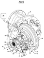
Figure 1 is a perspective view of an axle assembly. -
Figure 2 is a perspective view of a differential carrier of the axle assembly. -
Figure 3 is a section view of the axle assembly along section line 3-3. - As required, detailed embodiments of the present invention are disclosed herein; however, it is to be understood that the disclosed embodiments are merely exemplary of the invention that may be embodied in various and alternative forms. The figures are not necessarily to scale; some features may be exaggerated or minimized to show details of particular components. Therefore, specific structural and functional details disclosed herein are not to be interpreted as limiting, but merely as a representative basis for teaching one skilled in the art to variously employ the present invention.
- Referring to
Figure 1 , anexemplary axle assembly 10 is shown. Theaxle assembly 10 may be provided with a vehicle, such as a motor vehicle like a truck, bus, farm equipment, military transport or weaponry vehicle, or cargo loading equipment for land, air, or marine vessels. Theaxle assembly 10 may be configured to provide torque to at least one associated wheel assembly. Referring toFigures 1-3 , theaxle assembly 10 may include adifferential carrier 20, anaxle housing 22, aninput shaft 24, aring gear 26, adifferential unit 28, afirst output shaft 30, asecond output shaft 32, aclutch collar 34, abearing cap 36, and a clutchcollar actuator mechanism 38. - Referring to
Figure 1 , thedifferential carrier 20 and theaxle housing 22 may cooperate to define acavity 40 that may receive various components of theaxle assembly 10. Thedifferential carrier 20 may be mounted to theaxle housing 22 and may support thedifferential unit 28 and its associated components to facilitate assembly of theaxle assembly 10. Thedifferential carrier 20 and/or theaxle housing 22 may facilitate mounting of theaxle assembly 10 to the vehicle. - The
input shaft 24 may receive torque from a power source. For example, theinput shaft 24 may be operatively coupled to a transmission, a transfer case, or another axle assembly that may receive torque from a motor or engine. In at least one embodiment, theinput shaft 24 may extend along and may rotate about afirst axis 42. Theinput shaft 24 may be operatively connected to thering gear 26 and may provide torque to thering gear 26. - Referring to
Figures 2 and3 , thering gear 26 may be configured to rotate about asecond axis 44. Thering gear 26 may have acenter hole 46 and a set ofteeth 48. Thecenter hole 46 may extend around thesecond axis 44. The set ofteeth 48 may be arranged around thecenter hole 46 and may engage and mate with corresponding teeth on another component, such as a pinion gear that may be associated with theinput shaft 24. - The
differential unit 28 may be disposed in thecavity 40 defined by thedifferential carrier 20 and theaxle housing 22. Thedifferential unit 28 may support thering gear 26. Thedifferential unit 28 may be rotatably supported by one ormore bearings 50 that may be disposed within the cavity. Thebearing 50 may be supported by the bearingcap 36 of thedifferential carrier 20 and may be a roller bearing that may include a plurality of rolling elements, such as balls, cones, or rollers that may be disposed between an inner race and an outer race. Thedifferential unit 28 may be configured to control rotation of thefirst output shaft 30 with respect to thesecond output shaft 32. For example, thedifferential unit 28 may permit the first andsecond output shafts second output shafts clutch collar 34. As is best shown inFigure 3 , thedifferential unit 28 may be generally disposed in thecenter hole 46 of thering gear 26. In at least one embodiment, thedifferential unit 28 may include afirst output gear 60, asecond output gear 62, acase 64, aspider 66, and one or more pinion gears 68. - The
first output gear 60 may be disposed proximate thefirst output shaft 30. For example, thefirst output gear 60 may extend around thesecond axis 44 and may have a center bore. The center bore may have a spline that may receive and engage a corresponding spline on thefirst output shaft 30 to inhibit rotation of thefirst output gear 60 with respect to thefirst output shaft 30. Thefirst output gear 60 may include a set of teeth that may be arranged on a side or face of thefirst output gear 60 that faces toward thespider 66 and one or more pinion gears 68. - The
second output gear 62 may be spaced apart from and disposed opposite thefirst output gear 60. Thesecond output gear 62 may have substantially the same configuration as thefirst output gear 60 in one or more embodiments. Thesecond output gear 62 may be disposed proximate thesecond output shaft 32 and may extend around thesecond axis 44 and may have a center bore. The center bore may have a spline that may receive and engage a corresponding spline on thesecond output shaft 32 to inhibit rotation of thesecond output gear 62 with respect to thesecond output shaft 32. Thesecond output gear 62 may also include a set of teeth that may be arranged on a side or face of thesecond output gear 62 that faces toward thespider 66 and one or more pinion gears 68. - The
case 64 may receive various components of thedifferential unit 28. Thecase 64 may be spaced apart from thedifferential carrier 20, theaxle housing 22, thefirst output shaft 30, and thesecond output shaft 32. In at least one embodiment, thecase 64 may include afirst case portion 70 and asecond case portion 72. - The
first case portion 70 may support thering gear 26. Thering gear 26 may be fixedly disposed on thefirst case portion 70. In addition, thefirst case portion 70 may receive and may be rotatably supported by abearing 50. As such, thering gear 26 and thefirst case portion 70 may rotate together about thesecond axis 44. Thefirst case portion 70 may include anopening 76. Theopening 76 may be configured as a through hole that may generally extend along thesecond axis 44. A portion of thefirst output shaft 30 and/or thesecond output shaft 32 may extend into theopening 76. Thesecond output gear 62 may be rotatably disposed in theopening 76 and may rotate about thesecond axis 44 with respect to thefirst case portion 70. - The
second case portion 72 may be disposed proximate and may engage thefirst case portion 70. Thesecond case portion 72 may be fixedly disposed on thefirst case portion 70 in any suitable manner, such as with one or more fasteners, a weld, or the like. Thesecond case portion 72 may be received in and may engage thebearing 50. In at least one embodiment, thesecond case portion 72 may include anopening 80 and acase gear 82. - The
opening 80 may be configured as a through hole that may extend along thesecond axis 44. Thefirst output shaft 30 may extend through theopening 80. In addition, thefirst output gear 60 may be rotatably disposed in theopening 80 such that thefirst output gear 60 may rotate about thesecond axis 44 with respect to thesecond case portion 72. - The
case gear 82 may include a set of teeth that may be arranged on a side or face of thesecond case portion 72. The teeth of thecase gear 82 may face towards theclutch collar 34. In addition, the teeth of thecase gear 82 may be radially disposed with respect to thesecond axis 44 and arranged around theopening 80. Thecase gear 82 may selectively engage corresponding teeth on theclutch collar 34 as will be discussed in more detail below. - The
spider 66 may be disposed in thecase 64 and may be configured to rotate about thesecond axis 44. Thespider 66 may rotate about thesecond axis 44 with respect to the first and/orsecond output shafts spider 66 may also include a set ofpins 90 that may extend away from thesecond axis 44. In at least one embodiment, thepins 90 may be arranged along afirst spider axis 92 and/or a second spider axis 94, which may be disposed substantially perpendicular to thesecond axis 44. Ends of thepins 90 may be received in thecase 64 and may be spaced apart from thedifferential carrier 20 so as not to interfere with rotation of thedifferential unit 28. Thepins 90 may be received between thefirst case portion 70 and thesecond case portion 72. - A
pinion gear 68 may be rotatably disposed on eachpin 90. Eachpinion gear 68 may be generally disposed in thecase 64 and may be retained on corresponding pins with a fastener, such as a thrust washer that may be coupled to or may engage thecase 64. Apinion gear 68 may rotate about acorresponding pin 90 andcorresponding spider axis 92, 94. Eachpinion gear 68 may include a set of teeth that mate with thefirst output gear 60 and thesecond output gear 62. - The
first output shaft 30 may help connect theaxle assembly 10 to a vehicle wheel. For example, thefirst output shaft 30 may extend along thesecond axis 44 from thedifferential unit 28 towards a vehicle wheel. Thefirst output shaft 30 may include afirst spline 100. Thefirst spline 100 may be disposed near an end of thefirst output shaft 30 and may mate with a spline on thefirst output gear 60. As such, thefirst output shaft 30 may be inhibited from rotating with respect to thefirst output gear 60. Thesecond spline 102 may be spaced apart from thefirst spline 100 and may mate with a corresponding spline on theclutch collar 34. As such, theclutch collar 34 may slide along thefirst output shaft 30 but may be inhibited from rotating with respect to thesecond output shaft 32. - The
second output shaft 32 may help connect theaxle assembly 10 to another vehicle wheel. For example, thesecond output shaft 32 may extend from an opposite side of thedifferential unit 28 from thefirst output shaft 30 and may extend along thesecond axis 44 from thedifferential unit 28 towards a vehicle wheel. Thesecond output shaft 32 may be spaced apart from thefirst output shaft 30 and may include aspline 110. Thespline 110 may be disposed near an end of thesecond output shaft 32 and may mate with a spline on thesecond output gear 62. As such, thesecond output shaft 32 may be inhibited from rotating with respect to thesecond output gear 62. - The
clutch collar 34 may be disposed within thecavity 40 defined by thedifferential carrier 20 and theaxle housing 22. Theclutch collar 34 may be moveably disposed on thefirst output shaft 30. More specifically, theclutch collar 34 may be disposed on thefirst output shaft 30 and may be configured to move or slide along thesecond axis 44. Theclutch collar 34 may be generally ring-shaped and may include agear portion 120 and anannular groove 122. - The
gear portion 120 may include a set of teeth that may be arranged on a side or face of theclutch collar 34 that faces toward thecase 64. The teeth of thegear portion 120 may selectively engage thecase gear 82 of thesecond case portion 72. More specifically, thegear portion 120 may mate or mesh with the teeth of thecase gear 82 when theclutch collar 34 is in a locked position and may not mate or mesh with the teeth of thecase gear 82 when theclutch collar 34 is in an unlocked position. In the locked position, theclutch collar 34 may couple thecase 64 to thefirst output shaft 30 such that thecase 64 andfirst output shaft 30 rotate together about thesecond axis 44. As such, thefirst output shaft 30 and thesecond output shaft 32 may rotate together and may not rotate at different velocities. In the unlocked position, theclutch collar 34gear portion 120 may not mate or mesh with the teeth of thecase gear 82 and thus theclutch collar 34 does not couple thecase 64 to thefirst output shaft 30. As such, thefirst output shaft 30 and thesecond output shaft 32 may not rotate together and may rotate at different velocities. - The
annular groove 122 may be spaced apart from thegear portion 120. Theannular groove 122 may extend continuously around theclutch collar 34 and may receive a portion of the clutchcollar actuator mechanism 38 as will be described in more detail below. - Referring to
Figures 2 and3 , the bearingcap 36 may be disposed within thecavity 40 defined by thedifferential carrier 20 and theaxle housing 22. The bearingcap 36 may cooperate with thedifferential carrier 20 to receive and help secure thebearing 50. The bearingcap 36 may be fixedly disposed on thedifferential carrier 20. In at least one embodiment, the bearingcap 36 may include afirst portion 126 and asecond portion 128. - The
first portion 126 may cooperate with thedifferential carrier 20 to define anopening 130 that receives thebearing 50. Thefirst portion 126 may be disposed between thedifferential carrier 20 and thesecond portion 128. - The
first portion 126 may include first andsecond fastener holes second fastener holes bearing 50 and on opposite sides of thesecond portion 128. The first andsecond fastener holes second fasteners bearing cap 36 to thedifferential carrier 20. - The
second portion 128 may extend from thefirst portion 126. Thesecond portion 128 may be integral with thefirst portion 126 or may be provided as a separate component that may be attached to thefirst portion 126. Thesecond portion 128 may be disposed between the first andsecond fastener holes second fasteners second portion 128 may extend away from thedifferential carrier 20 such that thefirst portion 126 is disposed between thedifferential carrier 20 and thesecond portion 128. - As is best shown in
Figure 3 , thesecond portion 128 may have achamber 136 that may receive at least a portion of the clutchcollar actuator mechanism 38. Thechamber 136 may be defined by a firstchamber wall portion 138, a secondchamber wall portion 140, and astep surface 142. - The first
chamber wall portion 138 may be disposed proximate an end of thechamber 136. The firstchamber wall portion 138 may be disposed opposite a fork and may receive and engage a piston as will be discussed in more detail below. The firstchamber wall portion 138 may have afirst diameter 144. - The second
chamber wall portion 140 may be disposed in thechamber 136 between the firstchamber wall portion 138 and an opposite end of thesecond portion 128. The secondchamber wall portion 140 may have asecond diameter 146 that may be less than thefirst diameter 144. - The
step surface 142 may extend from the firstchamber wall portion 138 to the secondchamber wall portion 140. Thestep surface 142 may extend substantially perpendicular with respect to the firstchamber wall portion 138 and or the secondchamber wall portion 140 in one or more embodiments and may limit a travel distance of a piston. - The
second portion 128 may also have a firstinner surface 150, a firstouter surface 152, a secondinner surface 154, a secondouter surface 156, and agroove 158. - The first
inner surface 150 may face toward the secondouter surface 156. The firstinner surface 150 may cooperate with the secondouter surface 156 to define thegroove 158. The firstinner surface 150 may extend around or may be disposed about an actuator axis as will be discussed in more detail below. - The first
outer surface 152 may be disposed opposite the firstinner surface 150 and thegroove 158. The firstouter surface 152 may extend around the firstinner surface 150 and may extend around an actuator axis as will be discussed in more detail below. - The second
inner surface 154 may face toward an actuator axis and may extend from thechamber 136. The secondinner surface 154 may at least partially define a hole that may receive a portion of a piston as will be discussed in more detail below. - The second
outer surface 156 may be disposed opposite the secondinner surface 154. In addition, the secondouter surface 156 may extend around the secondinner surface 154 and may be disposed between the firstinner surface 150 and the secondinner surface 154. - The
groove 158 may be disposed between and may be defined by the firstinner surface 150 and the secondouter surface 156. Thegroove 158 may have anopen end 160 that may face away from thechamber 136. In addition, thegroove 158 may be spaced apart from and may not extend to thechamber 136. - The
first portion 126 may include ananti-rotation feature 164. Theanti-rotation feature 164 may extend away from a portion of thebearing cap 36. Theanti-rotation feature 164 may be configured as a protrusion or finger and may extend substantially parallel to thesecond axis 44. Theanti-rotation feature 164 may be disposed between theclutch collar 34 and the clutchcollar actuator mechanism 38. Theanti-rotation feature 164 may be disposed between thesecond portion 128 and thefirst output shaft 30. Theanti-rotation feature 164 may help position and inhibit rotation of the clutchcollar actuator mechanism 38 during assembly, removal, or maintenance, as will be discussed in more detail below. - The clutch
collar actuator mechanism 38 may facilitate the positioning of theclutch collar 34 along thesecond axis 44 relative to thefirst output shaft 30. The clutchcollar actuator mechanism 38 may be disposed within thecavity 40 defined by thedifferential carrier 20 and theaxle housing 22. Providing the clutchcollar actuator mechanism 38 inside theaxle assembly 10 may help reduce package space of theaxle assembly 10 and may help improve clearance to other vehicle components. The clutchcollar actuator mechanism 38 may be disposed proximate and may engage thesecond portion 128. The combination of theclutch collar 34 and the clutchcollar actuator mechanism 38 may collectively be referred to as a driver controlled differential lock ("DCDL"). In at least one embodiment, the clutchcollar actuator mechanism 38 may include anactuator 170 and afork 172. - The
actuator 170 may be configured to actuate thefork 172 and theclutch collar 34. Theactuator 170 may be completely disposed inside theaxle assembly 10. For example, theactuator 170 may be at least partially received within thechamber 136 and may be moveably disposed in thechamber 136 of thesecond portion 128. In at least one embodiment, theactuator 170 may extend along and may move along anactuator axis 174. Theactuator 170 may be of any suitable type, such as a pneumatic, hydraulic, vacuum, mechanical, or electromechanical actuator. In at least one embodiment, theactuator 170 may include a piston 180, afork mounting feature 182, and a biasingmember 184. - The piston 180 may include a
piston head 190 and apiston shaft 192. Thepiston head 190 and thepiston shaft 192 may be fixedly positioned with respect to each other and may be movably disposed within thechamber 136. Thepiston head 190 and thepiston shaft 192 may move in unison when the clutchcollar actuator mechanism 38 is actuated. The piston 180 may be provided with a pair of sealing rings, such as an o-ring, to form a pressurized vessel. A first sealing ring may be disposed about thepiston head 190. The first sealing ring may sealingly engage the firstchamber wall portion 138. A second sealing ring may be disposed about thepiston shaft 192. The second sealing ring may sealingly engage the secondinner surface 154. - The
piston head 190 may be configured to engage thestep surface 142 when the clutchcollar actuator mechanism 38 is in the extended position. The extended position may correspond to a disengaged or off position of the clutchcollar actuator mechanism 38. The engagement of thepiston head 190 with thestep surface 142 may inhibit further motion of the piston 180 to the left from the perspective shown inFigure 3 . - The
fork mounting feature 182 may operatively couple the piston 180 to thefork 172. Thefork mounting feature 182 may have any suitable configuration. For instance, the fork mounting feature may be a fastener, such as a bolt. Thefork mounting feature 182 may extend along theactuator axis 174, may extend through thefork 172 and may couple thepiston shaft 192 to thefork 172. - The biasing
member 184 may extend between thesecond portion 128 and thefork 172. The biasingmember 184 may be at least partially received within thegroove 158. The biasingmember 184 may at least partially extend around thefork mounting feature 182 and the piston 180. The biasingmember 184 may facilitate translation of thefork 172 with respect to theactuator 170 along theactuator axis 174. The biasingmember 184 may exert a biasing force on thefork 172 such that theclutch collar 34 is biased towards disengagement from thedifferential unit 28, or to the left from the perspective shown inFigure 3 . - Referring primarily to
Figure 2 , thefork 172 may be disposed within thecavity 40 defined by thedifferential carrier 20 and theaxle housing 22. Thefork 172 may operatively connect theactuator 170 to theclutch collar 34. In at least one embodiment, thefork 172 may include afirst fork portion 200, asecond fork portion 202, afirst arm 204, asecond arm 206, and afork opening 208. - The
first fork portion 200 may be disposed proximate afirst end 210 of thefork 172 that may be disposed proximate theclutch collar 34. Thefirst fork portion 200 may be spaced apart from and disposed opposite thesecond fork portion 202. As is best shown inFigure 2 , thefirst fork portion 200 may be disposed substantially parallel to but may not be coplanar with thesecond fork portion 202. In one or more embodiments, thefirst fork portion 200 may be substantially coplanar with thesecond fork portion 202 such that thefork 172 may form a straight fork.Thefirst fork portion 200 may include afirst prong 212 and asecond prong 214. - The
first prong 212 may be disposed proximate and may engage theclutch collar 34. For instance, thefirst prong 212 may be received within theannular groove 122 of theclutch collar 34. Thefirst prong 212 may include adetection feature 220. - The
detection feature 220 may be disposed at an end of thefirst prong 212. Thedetection feature 220 may have any suitable configuration. For example, thedetection feature 220 may be configured as an arm, a bolt, or a pin that may extend from thefirst prong 212 or may be integrally formed with thefirst fork portion 200. - The
second prong 214 may be disposed opposite thefirst prong 212. Thesecond prong 214 may be disposed substantially parallel to thefirst prong 212. Thesecond prong 214 may be disposed proximate and may engage theclutch collar 34. Thesecond prong 214 may be received within theannular groove 122 of theclutch collar 34. - The
second fork portion 202 may be disposed proximate asecond end 216 of thefork 172. Thesecond fork portion 202 may be disposed on an opposite side of the fork opening 208 from thefirst fork portion 200. Thesecond fork portion 202 may include an opening that may receive thefork mounting feature 182. - The
first arm 204 and thesecond arm 206 may extend from thefirst fork portion 200 to thesecond fork portion 202. Thefirst arm 204 and thesecond arm 206 may be spaced apart from each other and may be disposed on opposite sides of thefork opening 208. In one or more embodiments, the first andsecond arms first fork portion 200 and thesecond fork portion 202. As such, thefirst fork portion 200 may be offset from and may not be coplanar with thesecond fork portion 202. In one or more embodiments, the first andsecond arms first fork portion 200 and thesecond fork portion 202. - The
fork opening 208 may be disposed between and may be at least partially defined by thefirst fork portion 200, thesecond fork portion 202, thefirst arm 204 and thesecond arm 206. Thefork opening 208 may be configured to receive theanti-rotation feature 164 such that theanti-rotation feature 164 limits rotation of thefork 172 aboutactuator axis 174 to facilitate assembly. As such, theanti-rotation feature 164 may allow theaxle assembly 10 be provided without a caging screw during assembly or removal of thedifferential carrier 20 from theaxle housing 22. - Referring to
Figure 3 , asensor 230 may extend at least partially through asensor hole 232 in thedifferential carrier 20. Thesensor 230 may be configured to detect a position of the clutchcollar actuator mechanism 38. Thesensor 230 may be of any suitable type and may or may not contact the clutchcollar actuator mechanism 38. In one or more embodiments, thesensor 230 may detect the position of a portion of thefork 172. More specifically, thesensor 230 may detect the position of thedetection feature 220. For instance, thesensor 230 may detect or contact thedetection feature 220 when thefork 172 and the clutchcollar actuator mechanism 38 are in the retracted position. The retracted position may correspond to an engage or on position of the clutchcollar actuator mechanism 38. Thesensor 230 may not detect or contact thedetection feature 220 of thefork 172 when thefork 172 and the clutchcollar actuator mechanism 38 are in the extended position. Thesensor 230 may provide data or a signal indicative of the position of the clutchcollar actuator mechanism 38 to a controller or monitoring system to facilitate monitoring and/or control of the clutchcollar actuator mechanism 38. - Operation of the clutch
collar actuator mechanism 38 will now be discussed. A pressurizedfluid source 240 may be associated with theaxle assembly 10. The pressurizedfluid source 240 may provide a pressurized fluid to actuate the actuator. The pressurizedfluid source 240 may be fluidly connected to the actuator. In at least one embodiment, the pressurizedfluid source 240 may be fluidly connected to afirst port 242. Thefirst port 242 may be provided with thedifferential carrier 20 or theaxle housing 22. Thefirst port 242 may provide access to the inside of theaxle assembly 10. Thefirst port 242 may be fluidly connected to or may receive aconduit 244. Theconduit 244, which may be a hose or tube, may be at least partially disposed inside theaxle assembly 10 and may be fluidly connected to the actuator. For instance, theconduit 244 may be fluidly connected to asecond port 246. Thesecond port 246 may be provided with thebearing cap 36. For instance, thesecond port 246 may be fluidly connected to thechamber 136 of thesecond portion 128. Pressurized fluid from the pressurizedfluid source 240 may be provided to thechamber 136 to actuate the actuator 170 from the extended position to the retracted position or to the right from the perspective shown inFigure 3 as shown in solid lines. Theclutch collar 34 may be engaged with thedifferential unit 28 when theactuator 170 is in the retracted position. Releasing or venting pressurized fluid from thechamber 136 may allow the piston 180 to move from the retracted position to the extended position under the biasing force of the biasingmember 184. The extended position is shown in phantom inFigure 3 . Movement of the piston 180 to the left from the perspective shown may be inhibited when the piston 180 engages thestep surface 142. Theclutch collar 34 may be disengaged from thedifferential unit 28 when theactuator 170 and thefork 172 are in the extended position. Actuation of theclutch collar 34 may or may not be operator controlled and the clutch collar may be actuated when the vehicle is stationary or moving. - While exemplary embodiments are described above, it is not intended that these embodiments describe all possible forms of the invention. Rather, the words used in the specification are words of description rather than limitation, and it is understood that various changes may be made without departing from the spirit and scope of the invention. Additionally, the features of various implementing embodiments may be combined to form further embodiments of the invention.
Claims (15)
- An axle assembly comprising:first and second output shafts;a differential unit that controls rotation of the first output shaft with respect to the second output shaft;a clutch collar moveably disposed on the first output shaft that selectively engages the differential unit; anda bearing that rotatably supports the differential unit;a differential carrier that supports the bearing;a bearing cap that is fixedly disposed on the differential carrier, the bearing cap including:a first portion that cooperates with the differential carrier to define an opening that receives the bearing; anda second portion that extends from the first portion, wherein the second portion has a chamber that receives an actuator that actuates the clutch collar; anda fork that operatively connects the actuator to the clutch collar.
- The axle assembly of claim 1 wherein the first portion is disposed between the differential carrier and the second portion.
- The axle assembly of claim 2 wherein the first portion has first and second fastener holes that are disposed on opposite sides of the bearing that receive first and second fasteners that couple the bearing cap to the differential carrier, wherein the second portion is disposed between the first and second fastener holes.
- The axle assembly of claim 1 wherein the actuator moves the fork between an extended position and a retracted position, wherein the clutch collar is disengaged from the differential unit when the fork is in the extended position and the clutch collar engages the differential unit when the fork is in the retracted position.
- The axle assembly of claim 4 wherein the actuator includes a piston that is moveably disposed within the chamber and that is connected to the fork.
- The axle assembly of claim 5 wherein the piston engages the fork and is connected to the fork with a fork mounting feature that extends through the fork to the actuator.
- The axle assembly of claim 5 wherein the second portion has a groove that extends around the piston, wherein the groove receives a biasing member that exerts a biasing force on the fork to bias the clutch collar to disengage the differential unit.
- The axle assembly of claim 7 wherein the second portion has a first inner surface and a second outer surface that is disposed opposite the first inner surface, wherein the first inner surface and the second outer surface cooperate to define the groove.
- The axle assembly of claim 1 wherein the differential carrier includes a first port that is configured to receive a pressurized fluid and the second portion includes a second port that is fluidly connected to the chamber, wherein the first port is fluidly connected to the second port with a conduit.
- The axle assembly of claim 1 wherein the bearing cap has an anti-rotation feature that extends away from the first portion and the fork has a fork opening that receives the anti-rotation feature, wherein the anti-rotation feature limits rotation of the fork about an actuator axis.
- The axle assembly of claim 10 wherein the anti-rotation feature is disposed between the actuator and the clutch collar.
- The axle assembly of claim 10 wherein the fork includes:first and second prongs disposed proximate a first end of the fork, anda fork mounting feature disposed proximate a second end of the fork that is disposed opposite the first end, wherein the fork opening is disposed between the first and second prongs and the fork mounting feature.
- The axle assembly of claim 12 wherein the fork includes a first fork portion that includes the first and second prongs, a second fork portion that includes the fork mounting feature, and first and second arms that extend from the first fork portion to the second fork portion, wherein the fork opening is disposed between the first and second arms, and the fork opening is disposed between the first fork portion and the second fork portion, wherein the first fork portion is disposed substantially parallel to the second fork portion.
- The axle assembly of claim 1 wherein the differential unit supports a ring gear and the second portion is disposed between the ring gear and the fork.
- The axle assembly of claim 1 further comprising a sensor disposed in the differential carrier, wherein the fork includes first and second prongs that are disposed proximate the clutch collar, wherein the first prong includes a detection feature that is disposed at an end of the first prong, wherein the sensor detects the detection feature.
Applications Claiming Priority (1)
| Application Number | Priority Date | Filing Date | Title |
|---|---|---|---|
| US14/742,739 US9989139B2 (en) | 2015-06-18 | 2015-06-18 | Axle assembly having a clutch collar actuator |
Publications (1)
| Publication Number | Publication Date |
|---|---|
| EP3115246A1 true EP3115246A1 (en) | 2017-01-11 |
Family
ID=55650244
Family Applications (1)
| Application Number | Title | Priority Date | Filing Date |
|---|---|---|---|
| EP16162758.3A Withdrawn EP3115246A1 (en) | 2015-06-18 | 2016-03-30 | Axle assembly having a clutch collar actuator |
Country Status (4)
| Country | Link |
|---|---|
| US (1) | US9989139B2 (en) |
| EP (1) | EP3115246A1 (en) |
| CN (1) | CN106256563B (en) |
| BR (1) | BR102016013749A2 (en) |
Families Citing this family (8)
| Publication number | Priority date | Publication date | Assignee | Title |
|---|---|---|---|---|
| EP3171048B1 (en) | 2015-11-20 | 2020-10-07 | Meritor Commercial Vehicle Systems India Private Limited | Vehicle drivetrain assembly having a clutch collar actuator mechanism |
| US10156289B2 (en) * | 2017-03-07 | 2018-12-18 | Meritor do Brasil Sistemas Automotivos Ltda. | Axle assembly having multiple clutch collars |
| US10703202B2 (en) | 2018-02-12 | 2020-07-07 | Arvinmeritor Technology, Llc | Drive axle assembly with clutch collar |
| US10357997B1 (en) | 2018-02-20 | 2019-07-23 | Arvinmeritor Technology, Llc | Drive axle assembly with moveable axle shaft and method of operation |
| JP7416586B2 (en) * | 2019-09-03 | 2024-01-17 | ジーケーエヌ オートモーティブ リミテッド | differential device |
| US11654769B2 (en) * | 2020-09-30 | 2023-05-23 | Gkn Automotive Limited | Driveline unit housing |
| US11732794B2 (en) * | 2021-06-29 | 2023-08-22 | Arvinmeritor Technology, Llc | Axle assembly having a lubricant reservoir |
| KR102563813B1 (en) * | 2021-08-26 | 2023-08-10 | 현대트랜시스 주식회사 | Axle assembly of electric vehicle |
Citations (3)
| Publication number | Priority date | Publication date | Assignee | Title |
|---|---|---|---|---|
| EP1203901A2 (en) * | 2000-10-25 | 2002-05-08 | Dana Corporation | Wheel differential shift mechanism |
| US20020198076A1 (en) * | 2001-06-19 | 2002-12-26 | Mack Trucks, Inc. | Enclosed axle differential lock mechanism |
| US20070199404A1 (en) | 2004-02-28 | 2007-08-30 | Kam Differentials Ltd. | Differential locking system |
Family Cites Families (6)
| Publication number | Priority date | Publication date | Assignee | Title |
|---|---|---|---|---|
| US5673777A (en) * | 1995-08-11 | 1997-10-07 | Eaton Corporation | Differential lock assembly spacer system |
| CN2635406Y (en) | 2003-05-14 | 2004-08-25 | 熊世民 | Back bridge differential lock device |
| JP4313826B2 (en) * | 2007-04-24 | 2009-08-12 | 株式会社エフ・シー・シー | Power transmission device |
| US20100041506A1 (en) * | 2008-08-15 | 2010-02-18 | Kenneth Cooper | Axle shaft disconnect assembly |
| CN102358175A (en) | 2011-09-02 | 2012-02-22 | 重庆大江工业有限责任公司 | Upper-offset through type driving axle |
| US9140349B1 (en) * | 2014-04-23 | 2015-09-22 | American Axle & Manufacturing, Inc. | Compact axle assembly with locking differential |
-
2015
- 2015-06-18 US US14/742,739 patent/US9989139B2/en active Active
-
2016
- 2016-01-25 CN CN201610048308.2A patent/CN106256563B/en active Active
- 2016-03-30 EP EP16162758.3A patent/EP3115246A1/en not_active Withdrawn
- 2016-06-14 BR BR102016013749-7A patent/BR102016013749A2/en not_active Application Discontinuation
Patent Citations (3)
| Publication number | Priority date | Publication date | Assignee | Title |
|---|---|---|---|---|
| EP1203901A2 (en) * | 2000-10-25 | 2002-05-08 | Dana Corporation | Wheel differential shift mechanism |
| US20020198076A1 (en) * | 2001-06-19 | 2002-12-26 | Mack Trucks, Inc. | Enclosed axle differential lock mechanism |
| US20070199404A1 (en) | 2004-02-28 | 2007-08-30 | Kam Differentials Ltd. | Differential locking system |
Also Published As
| Publication number | Publication date |
|---|---|
| US20160369879A1 (en) | 2016-12-22 |
| CN106256563A (en) | 2016-12-28 |
| BR102016013749A2 (en) | 2018-08-14 |
| CN106256563B (en) | 2019-03-22 |
| US9989139B2 (en) | 2018-06-05 |
Similar Documents
| Publication | Publication Date | Title |
|---|---|---|
| US9989139B2 (en) | Axle assembly having a clutch collar actuator | |
| EP3385106B1 (en) | Axle assembly having multiple clutch collars | |
| EP3130501B1 (en) | Axle assembly having a clutch collar actuator mechanism | |
| EP3561330B1 (en) | Axle assembly having a wheel end disconnect and method of control | |
| US10500941B2 (en) | Axle assembly having an electric motor module and a shift mechanism | |
| US11273700B2 (en) | Axle assembly having an electric motor module | |
| EP3446906B1 (en) | Axle assembly having an electric motor module and a gear reduction module | |
| EP3437913B1 (en) | Axle assembly having a countershaft | |
| US10864818B2 (en) | Method of controlling a drive axle system | |
| US10591037B2 (en) | Drive axle system having a planetary interaxle differential unit | |
| US8944952B2 (en) | Differential assembly having a clutch collar actuator mechanism | |
| EP3171048B1 (en) | Vehicle drivetrain assembly having a clutch collar actuator mechanism | |
| EP3608144A1 (en) | Method of controlling a drive axle system | |
| US11391370B2 (en) | Shift fork actuation assembly |
Legal Events
| Date | Code | Title | Description |
|---|---|---|---|
| PUAI | Public reference made under article 153(3) epc to a published international application that has entered the european phase |
Free format text: ORIGINAL CODE: 0009012 |
|
| AK | Designated contracting states |
Kind code of ref document: A1 Designated state(s): AL AT BE BG CH CY CZ DE DK EE ES FI FR GB GR HR HU IE IS IT LI LT LU LV MC MK MT NL NO PL PT RO RS SE SI SK SM TR |
|
| AX | Request for extension of the european patent |
Extension state: BA ME |
|
| STAA | Information on the status of an ep patent application or granted ep patent |
Free format text: STATUS: THE APPLICATION IS DEEMED TO BE WITHDRAWN |
|
| 18D | Application deemed to be withdrawn |
Effective date: 20170712 |