EP3115187B1 - Control solution for self-healing materials - Google Patents
Control solution for self-healing materials Download PDFInfo
- Publication number
- EP3115187B1 EP3115187B1 EP16177941.8A EP16177941A EP3115187B1 EP 3115187 B1 EP3115187 B1 EP 3115187B1 EP 16177941 A EP16177941 A EP 16177941A EP 3115187 B1 EP3115187 B1 EP 3115187B1
- Authority
- EP
- European Patent Office
- Prior art keywords
- sensor element
- server
- triggering
- testing procedure
- autonomic
- Prior art date
- Legal status (The legal status is an assumption and is not a legal conclusion. Google has not performed a legal analysis and makes no representation as to the accuracy of the status listed.)
- Active
Links
Images

Classifications
-
- G—PHYSICS
- G01—MEASURING; TESTING
- G01N—INVESTIGATING OR ANALYSING MATERIALS BY DETERMINING THEIR CHEMICAL OR PHYSICAL PROPERTIES
- G01N3/00—Investigating strength properties of solid materials by application of mechanical stress
- G01N3/08—Investigating strength properties of solid materials by application of mechanical stress by applying steady tensile or compressive forces
-
- B—PERFORMING OPERATIONS; TRANSPORTING
- B29—WORKING OF PLASTICS; WORKING OF SUBSTANCES IN A PLASTIC STATE IN GENERAL
- B29C—SHAPING OR JOINING OF PLASTICS; SHAPING OF MATERIAL IN A PLASTIC STATE, NOT OTHERWISE PROVIDED FOR; AFTER-TREATMENT OF THE SHAPED PRODUCTS, e.g. REPAIRING
- B29C73/00—Repairing of articles made from plastics or substances in a plastic state, e.g. of articles shaped or produced by using techniques covered by this subclass or subclass B29D
- B29C73/16—Auto-repairing or self-sealing arrangements or agents
- B29C73/22—Auto-repairing or self-sealing arrangements or agents the article containing elements including a sealing composition, e.g. powder being liberated when the article is damaged
-
- G—PHYSICS
- G01—MEASURING; TESTING
- G01N—INVESTIGATING OR ANALYSING MATERIALS BY DETERMINING THEIR CHEMICAL OR PHYSICAL PROPERTIES
- G01N3/00—Investigating strength properties of solid materials by application of mechanical stress
- G01N3/60—Investigating resistance of materials, e.g. refractory materials, to rapid heat changes
-
- B—PERFORMING OPERATIONS; TRANSPORTING
- B29—WORKING OF PLASTICS; WORKING OF SUBSTANCES IN A PLASTIC STATE IN GENERAL
- B29C—SHAPING OR JOINING OF PLASTICS; SHAPING OF MATERIAL IN A PLASTIC STATE, NOT OTHERWISE PROVIDED FOR; AFTER-TREATMENT OF THE SHAPED PRODUCTS, e.g. REPAIRING
- B29C35/00—Heating, cooling or curing, e.g. crosslinking or vulcanising; Apparatus therefor
- B29C35/02—Heating or curing, e.g. crosslinking or vulcanizing during moulding, e.g. in a mould
- B29C35/0272—Heating or curing, e.g. crosslinking or vulcanizing during moulding, e.g. in a mould using lost heating elements, i.e. heating means incorporated and remaining in the formed article
Definitions
- the invention concerns in general the technical field of communication solutions. Especially the invention concerns control solutions arranged by means communication technology within an area of self-healing materials.
- the development in an area of so called self-healing materials has paved a way to implement further solutions in the area.
- the self-healing materials are a class of smart materials that have a structurally incorporated ability to repair damage developed in the material in one way or another.
- Some self-healing materials known as non-autonomic extrinsic self-healing materials, are such that in order to initiate a repair process an external triggering shall be provided to the material.
- the external triggering may e.g. be a provision of additional light, heat, laser beam, radiation or electricity to the material element.
- a non-limiting example of a non-autonomic extrinsic self-healing material is polymeric nanoparticles.
- An objective of the invention is to present a method, a server and a system for controlling a repair of at least one non-autonomic extrinsic self-healing material in an object. Another objective of the invention is that the method, the server and the system provide an optimized self-healing process through the controlling.
- a method for controlling a repair of at least one non-autonomic extrinsic self-healing material in an object comprises: triggering at least one sensor element embedded in the at least one non-autonomic extrinsic self-healing material to initiate a testing procedure for the at least one non-autonomic extrinsic self-healing material; receiving a result of the testing procedure in the server; analysing the result of the testing procedure; determining, in response to a detection in the analysing that the at least one non-autonomic extrinsic self-healing material requires a repair process, capability information of the sensor element with an inquiry to one of: the at least one sensor element, a database; the capability information being indicative on a kind of repair process the sensor element is capable of; receiving the capability information in the server; determining a triggering instruction to the sensor element in the server on the basis of the capability information; delivering the triggering instruction to utilize an applicable capability
- the triggering instruction may further comprise an instruction for re-triggering the testing procedure.
- the instruction for re-triggering the testing procedure may also comprise a time value for a timer implemented in the sensor element. The time value may be dependent on the predetermined repair process.
- a server for controlling a repair of at least one non-autonomic extrinsic self-healing material in an object comprises at least one processor, and at least one memory storing at least one portion of computer program code, wherein the processor being configured to cause the server at least to perform: trigger at least one sensor element embedded in the at least one non-autonomic extrinsic self-healing material to initiate a testing procedure for the at least one non-autonomic extrinsic self-healing material; receive a result of the testing procedure; analyse the result of the testing procedure; determine, in response to a detection in the analysing that the at least one non-autonomic extrinsic self-healing material requires a repair process, capability information of the
- the server may be configured to add an instruction for re-triggering the testing procedure in the triggering instruction.
- the server may also be configured to add a time value for a timer implemented in the sensor element in the instruction for re-triggering the testing procedure.
- the time value may be dependent on the predetermined repair process.
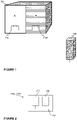
- Figure 1 discloses a non-limiting example of an environment in which the invention may be implemented.
- an object 100 comprising at least two different non-autonomic extrinsic self-healing materials (marked with A and B in Figure 1 ).
- the object 100 may be some sort of structure in a building, for example.
- One or more sensor elements 110A, 110B are embedded in the object so that at least one sensor element 110A, 110B is embedded in the non-autonomic extrinsic self-healing material to be monitored.
- the embedding may advantageously be implemented so that the sensor element 110A, 110B is capable of performing tasks as will be discussed in the following.
- the sensor elements 110A, 110B are communicatively coupled to a server 150.
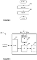
- FIG. 2 illustrates in an exemplified manner a sensor element 110A, 110B according to an embodiment of the invention.
- the sensor element 110A, 110B comprises at least one sensor device 210, at least one actuating device 220 and at least one communication device 230, such as a wired or wireless modem.
- the sensor device 210 may comprise one or more sensors, which is configured to obtain predetermined information on the material to be measured.
- the predetermined information may e.g. be any parameter by means of which it is possible to determine if there is a defect in the material monitored or not.
- the sensor device 210 may be a strain gauge configured to obtain information on a tension of the object to be measured. A change in tension may, for example, indicate that there is a crack in the object.
- the actuating device 220 may be a device which is capable of providing at least one type of external triggering to the material in question in order to initiate the self-healing process to the detected defect if possible.
- the external trigger may e.g. be light, heat, radiation or electricity provided to the material.
- Some simple non-limiting examples of the actuating device are led (light emitting diodes) or heat resistance.
- the communication device may be, as already mentioned, a wired or wireless modem performing operations by means of which the sensor element may communication internally and externally.
- the internal communication refers to a communication between the mentioned devices within the sensor element.
- External communication refers to a communication with the server 150.
- the sensor element 110A, 110B as illustrated in Figure 2 does not disclose any separate processing unit for managing and controlling the operation of the sensor element, but it may comprise such a separate unit or such an operation may be integrated in any of the described devices.
- Figure 3 illustrates schematically a principle of the method according to an embodiment of the invention.
- the method comprises two stages wherein the first stage 310 is an analysis stage and the second stage is a repair stage 320.
- the analysis stage 310 information is obtained from the sensor element and it is analysed. Based on the analysis a repair process related actions are performed in the repair stage 320.
- Figure 4 illustrates schematically an example of the method according to an embodiment of the invention as a flow chart in more detail.
- the method is described from the server 150 point of view and it relates to a controlling of a repair of at least one non-autonomic extrinsic self-healing material in an object comprising multiple non-autonomic extrinsic self-healing materials.
- the server 150 is configured to trigger 410 at least one sensor element embedded in the at least one non-autonomic extrinsic self-healing material to initiate a testing procedure for the at least one non-autonomic extrinsic self-healing material.
- the testing procedure is performed in the sensor element and a result of the testing procedure, i.e.
- the server may be configured to extract the measurement result or results from the received message and compare it to a reference value or values, which is stored in the server 150, or at least accessible by it.
- the reference value may be a theoretical value characteristic to the material in question or a previous measurement result, for instance.
- the message may comprise an identifier for identifying a sensor element or sensor device in order to obtain an applicable reference value for the comparison. Alternatively analysis may apply such values which were previously used successfully, deviating from predetermined reference value.
- the server 150 is configured to determine 440 what kind of repair process the sensor element may initiate through triggering. In other words, the aim of this step is to find out if the sensor element is capable of initiating a required repair process or not when there is need for such. The determination is either performed by inquiring it from the sensor element 110A, 110B or by initiating a query to a database storing the information.
- the server 150 is configured to determine 460 an applicable triggering instruction to the sensor element.
- the determination may comprise at least adjustment value, such as time or power parameter, for at least one actuating device residing in the sensor element.
- it may comprise a determination of an actuating device, which is to be triggered in order to initiate the repair process.
- the determination of the triggering instruction is at least partly dependent on the material in question.
- the server 150 may control the sensor element to operate accordingly by delivering instruction 470 to the sensor element in order to initiate a repair process in the non-autonomic extrinsic self-healing material in question by activating an applicable capability of the sensor element in question.
- the triggering instruction may e.g. be delivered in a predetermined message configured to transfer information either directly or indirectly between the server 150 and the sensor element 110A, 110B and any devices within the mentioned entities.
- the analysis 430 may provide information which one of the possible detections is the most critical and provide to it a higher priority than to the others. This may be implemented by determining which one of the measurement results deviates most from the reference value. Alternatively or in addition, it may be determined which one of the deviations is the most critical on a basis of some stored information. In such a case the determination step 460 of determining a triggering instruction may comprise a feature in which the triggering instruction is determined for the most critical detection, at least in a first place.
- the triggering instruction delivered to the sensor element 110A, 110B may comprise an instruction to re-triggering the testing procedure in the sensor element in question, or multiple sensor elements embedded in the object. This is advantageous in a sense that it is possible to detect immediately if the repair process has been successful or if the process shall be repeated.
- the delivery of the re-triggering instruction is depicted with dashed arrow line in Figure 4 .
- the server 150 may be configured to determine, from e.g. stored information accessible by the server 150, a time value for a timer configured to delay the re-triggering of the testing procedure.
- the time value may e.g. be dependent on the instructed repair process.
- the timer may be executed either in the server or in the sensor element in which case the time value is delivered to the sensor element. By means of the timer it is possible to adjust an optimal point of time when the testing procedure shall be re-initiated in order to see any effect of the previous repair process in the material.
- FIG. 5 discloses an example of a server 150 according to an embodiment of the invention.
- the server 150 may comprise one or more processors 510, one or more memories 520 being volatile or non-volatile for storing portions of computer program code 521a-521n and any data values, a communication interface 530 and possibly one or more user interface units 540.
- the mentioned elements are communicatively coupled to each other with e.g. an internal bus.
- the communication interface provides interface for communication with any external unit, such as with one or more network nodes, one or more data storages, one or more mobile terminals, for example.
- the communication interface is based on one or more known communication technologies, either wired or wireless, in order to communicate with an external unit in question.
- the processor 510 of the server 150 is at least configured to implement the method as described.
- the implementation of the method may be achieved by arranging the processor 510 to execute at least some portion of computer program code 521a-521n stored in the memory 520 causing the processor 510, and thus the server 150, to implement one or more method steps as described.
- the processor 510 is arranged to access the memory 520 and retrieve and store any information therefrom and thereto.
- the processor 510 is configured to control the communication through the communication interface 530 with any external unit.
- the processor 510 may also be configured to control the output of information, i.e. data.
- the processor 510 may also be configured to control storing of received and delivered information as well as processing it.
- the processor herein refers to any unit suitable for processing information and control the operation of the server, among other tasks.
- the mentioned operations may e.g. be implemented with a microcontroller solution with embedded software.
- the invention is not limited to a certain type of memory only, but any memory type suitable for storing the described pieces of information may be applied in the context of the present invention.
- a server 150 is arranged to communicate with one or more sensor elements 110A, 110B embedded in an object to be monitored.
- the present invention may also be implemented in such a manner that there is an intermediate terminal operating between the server 150 and the sensor element(s) 110A, 110B.
- the intermediate terminal is advantageously equipped with necessary hardware and software implementation in order to perform the tasks required.
- the intermediate terminal may, for example, be configured to trigger the testing procedure of the sensor element by communicating with the sensor element in question.
- the triggering may be implemented with some short range communication method, such as Bluetooth.
- both the intermediate terminal and the sensor element or sensor elements are equipped with the short range communication devices and the intermediate device may be configured to trigger the testing procedure.
- the intermediate terminal may be configured to operate as a link to the server, or even to perform at least some part of the analysis, in order to determine if the repair process shall be initiated or not.
- the intermediate device may be instructed to trigger the capability of the sensor element e.g. with the short range communication with the sensor element. This may be in response to an instruction from the server, especially if the server performs the analysis, or at least part of it.
- Other variations are also available in the utilization of an intermediate device in the method according to the present invention.
- the invention may be applied in a system in which the server according to the invention and at least one sensor element are communicatively coupled to perform the method as described.
- the system may comprise an intermediate terminal configured to operate as a link between the server and the at least one sensor element.
- the intermediate terminal may perform at least some of the functions of the server, e.g. as described above.
Landscapes
- Physics & Mathematics (AREA)
- Health & Medical Sciences (AREA)
- Life Sciences & Earth Sciences (AREA)
- Chemical & Material Sciences (AREA)
- Analytical Chemistry (AREA)
- Biochemistry (AREA)
- General Health & Medical Sciences (AREA)
- General Physics & Mathematics (AREA)
- Immunology (AREA)
- Pathology (AREA)
- Engineering & Computer Science (AREA)
- Mechanical Engineering (AREA)
- Telephonic Communication Services (AREA)
Description
- The invention concerns in general the technical field of communication solutions. Especially the invention concerns control solutions arranged by means communication technology within an area of self-healing materials.
- The development in an area of so called self-healing materials has paved a way to implement further solutions in the area. The self-healing materials are a class of smart materials that have a structurally incorporated ability to repair damage developed in the material in one way or another. Some self-healing materials, known as non-autonomic extrinsic self-healing materials, are such that in order to initiate a repair process an external triggering shall be provided to the material. The external triggering may e.g. be a provision of additional light, heat, laser beam, radiation or electricity to the material element. A non-limiting example of a non-autonomic extrinsic self-healing material is polymeric nanoparticles.
- In case that a structure, i.e. an object, is manufactured from multiple non-autonomic extrinsic self-healing materials it is necessary to manage and control an initiation and operation of the repair process.
- In a document
US 2014/186476 A1 it is described an example of a self-healing system which is configured to determine at least one damage location in a composite panel and to determine a target healing area based on the damage location. The healing is performed by activating individual heating elements in the panel to cause localized heating. - Hence, there is need to develop solution by means of which it is possible to control the repair process of said self-healing materials in an optimal manner.
- An objective of the invention is to present a method, a server and a system for controlling a repair of at least one non-autonomic extrinsic self-healing material in an object. Another objective of the invention is that the method, the server and the system provide an optimized self-healing process through the controlling.
- The objectives of the invention are reached by a method and a server as defined by the respective independent claims.
- According to a first aspect, a method for controlling a repair of at least one non-autonomic extrinsic self-healing material in an object is provided wherein the method, performed by a server, comprises: triggering at least one sensor element embedded in the at least one non-autonomic extrinsic self-healing material to initiate a testing procedure for the at least one non-autonomic extrinsic self-healing material; receiving a result of the testing procedure in the server; analysing the result of the testing procedure; determining, in response to a detection in the analysing that the at least one non-autonomic extrinsic self-healing material requires a repair process, capability information of the sensor element with an inquiry to one of: the at least one sensor element, a database; the capability information being indicative on a kind of repair process the sensor element is capable of; receiving the capability information in the server; determining a triggering instruction to the sensor element in the server on the basis of the capability information; delivering the triggering instruction to utilize an applicable capability of the sensor element to the sensor element.
- The triggering instruction may further comprise an instruction for re-triggering the testing procedure. The instruction for re-triggering the testing procedure may also comprise a time value for a timer implemented in the sensor element. The time value may be dependent on the predetermined repair process. According to a second aspect, a server for controlling a repair of at least one non-autonomic extrinsic self-healing material in an object is provided, the server comprises at least one processor, and at least one memory storing at least one portion of computer program code, wherein the processor being configured to cause the server at least to perform: trigger at least one sensor element embedded in the at least one non-autonomic extrinsic self-healing material to initiate a testing procedure for the at least one non-autonomic extrinsic self-healing material; receive a result of the testing procedure; analyse the result of the testing procedure; determine, in response to a detection in the analysing that the at least one non-autonomic extrinsic self-healing material requires a repair process, capability information of the sensor element with an inquiry to one of: the at least one sensor element, a database; the capability information being indicative on a kind of repair process the sensor element is capable of; receive the capability information; determine a triggering instruction to the sensor element on the basis of the capability information; deliver the triggering instruction to utilize an applicable capability of the sensor element to the sensor element.
- The server may be configured to add an instruction for re-triggering the testing procedure in the triggering instruction. The server may also be configured to add a time value for a timer implemented in the sensor element in the instruction for re-triggering the testing procedure. The time value may be dependent on the predetermined repair process.
- The exemplary embodiments of the invention presented in this patent application are not to be interpreted to pose limitations to the applicability of the appended claims. The verb "to comprise" is used in this patent application as an open limitation that does not exclude the existence of also un-recited features. The features recited in depending claims are mutually freely combinable unless otherwise explicitly stated.
- The novel features which are considered as characteristic of the invention are set forth in particular in the appended claims. The invention itself, however, both as to its construction and its method of operation, together with additional objectives and advantages thereof, will be best understood from the following description of specific embodiments when read in connection with the accompanying drawings.
- The embodiments of the invention are illustrated by way of example, and not by way of limitation, in the figures of the accompanying drawings.
-
Figure 1 illustrates schematically an example of an environment in which the invention is implemented. -
Figure 2 illustrates schematically in an exemplified manner a sensor element according to an embodiment of the invention. -
Figure 3 illustrates schematically a principle of the method according to an embodiment of the invention. -
Figure 4 illustrates schematically an example of the method according to an embodiment of the invention in more detail. -
Figure 5 illustrates schematically an example of a server according to an embodiment of the invention. -
Figure 1 discloses a non-limiting example of an environment in which the invention may be implemented. In the environment anobject 100 comprising at least two different non-autonomic extrinsic self-healing materials (marked with A and B inFigure 1 ). Theobject 100 may be some sort of structure in a building, for example. One ormore sensor elements sensor element sensor element sensor elements server 150. -
Figure 2 illustrates in an exemplified manner asensor element sensor element sensor device 210, at least oneactuating device 220 and at least onecommunication device 230, such as a wired or wireless modem. Thesensor device 210 may comprise one or more sensors, which is configured to obtain predetermined information on the material to be measured. The predetermined information may e.g. be any parameter by means of which it is possible to determine if there is a defect in the material monitored or not. For example, thesensor device 210 may be a strain gauge configured to obtain information on a tension of the object to be measured. A change in tension may, for example, indicate that there is a crack in the object. The actuatingdevice 220, in turn, may be a device which is capable of providing at least one type of external triggering to the material in question in order to initiate the self-healing process to the detected defect if possible. The external trigger may e.g. be light, heat, radiation or electricity provided to the material. Some simple non-limiting examples of the actuating device are led (light emitting diodes) or heat resistance. The communication device may be, as already mentioned, a wired or wireless modem performing operations by means of which the sensor element may communication internally and externally. The internal communication refers to a communication between the mentioned devices within the sensor element. External communication refers to a communication with theserver 150. Thesensor element Figure 2 does not disclose any separate processing unit for managing and controlling the operation of the sensor element, but it may comprise such a separate unit or such an operation may be integrated in any of the described devices. -
Figure 3 illustrates schematically a principle of the method according to an embodiment of the invention. The method comprises two stages wherein thefirst stage 310 is an analysis stage and the second stage is arepair stage 320. In theanalysis stage 310 information is obtained from the sensor element and it is analysed. Based on the analysis a repair process related actions are performed in therepair stage 320. -
Figure 4 illustrates schematically an example of the method according to an embodiment of the invention as a flow chart in more detail. The method is described from theserver 150 point of view and it relates to a controlling of a repair of at least one non-autonomic extrinsic self-healing material in an object comprising multiple non-autonomic extrinsic self-healing materials. In the method theserver 150 is configured to trigger 410 at least one sensor element embedded in the at least one non-autonomic extrinsic self-healing material to initiate a testing procedure for the at least one non-autonomic extrinsic self-healing material. The testing procedure is performed in the sensor element and a result of the testing procedure, i.e. obtained measurement results from the sensor device, is received, which result is transmitted to theserver 150 with a message. In response to areceipt 420 of the result of the testing procedure in theserver 150, the result of the testing procedure is analysed 430 in theserver 150. The server may be configured to extract the measurement result or results from the received message and compare it to a reference value or values, which is stored in theserver 150, or at least accessible by it. The reference value may be a theoretical value characteristic to the material in question or a previous measurement result, for instance. In order to determine a correct reference value the message may comprise an identifier for identifying a sensor element or sensor device in order to obtain an applicable reference value for the comparison. Alternatively analysis may apply such values which were previously used successfully, deviating from predetermined reference value. The previous examples of the analysis are not limiting and the analysis may be performed in any other way than described. In response to a detection that there is need to initiate a repair process of the at least one non-autonomic extrinsic self-healing material, theserver 150 is configured to determine 440 what kind of repair process the sensor element may initiate through triggering. In other words, the aim of this step is to find out if the sensor element is capable of initiating a required repair process or not when there is need for such. The determination is either performed by inquiring it from thesensor element receipt 450 of the capability information of thesensor element server 150 is configured to determine 460 an applicable triggering instruction to the sensor element. The determination may comprise at least adjustment value, such as time or power parameter, for at least one actuating device residing in the sensor element. Alternatively or in addition, it may comprise a determination of an actuating device, which is to be triggered in order to initiate the repair process. Naturally, the determination of the triggering instruction is at least partly dependent on the material in question. When the triggering instruction, i.e. necessary parameters, are determined by theserver 150, theserver 150 may control the sensor element to operate accordingly by deliveringinstruction 470 to the sensor element in order to initiate a repair process in the non-autonomic extrinsic self-healing material in question by activating an applicable capability of the sensor element in question. The triggering instruction may e.g. be delivered in a predetermined message configured to transfer information either directly or indirectly between theserver 150 and thesensor element - In case that the server receives measurement results from multiple sensor elements, either embedded in the same material or in the different materials, the
analysis 430 may provide information which one of the possible detections is the most critical and provide to it a higher priority than to the others. This may be implemented by determining which one of the measurement results deviates most from the reference value. Alternatively or in addition, it may be determined which one of the deviations is the most critical on a basis of some stored information. In such a case thedetermination step 460 of determining a triggering instruction may comprise a feature in which the triggering instruction is determined for the most critical detection, at least in a first place. - In some implementation of the present invention the triggering instruction delivered to the
sensor element Figure 4 . - Moreover, the
server 150 may be configured to determine, from e.g. stored information accessible by theserver 150, a time value for a timer configured to delay the re-triggering of the testing procedure. The time value may e.g. be dependent on the instructed repair process. The timer may be executed either in the server or in the sensor element in which case the time value is delivered to the sensor element. By means of the timer it is possible to adjust an optimal point of time when the testing procedure shall be re-initiated in order to see any effect of the previous repair process in the material. -
Figure 5 discloses an example of aserver 150 according to an embodiment of the invention. Theserver 150 may comprise one ormore processors 510, one ormore memories 520 being volatile or non-volatile for storing portions ofcomputer program code 521a-521n and any data values, acommunication interface 530 and possibly one or moreuser interface units 540. The mentioned elements are communicatively coupled to each other with e.g. an internal bus. The communication interface provides interface for communication with any external unit, such as with one or more network nodes, one or more data storages, one or more mobile terminals, for example. The communication interface is based on one or more known communication technologies, either wired or wireless, in order to communicate with an external unit in question. - The
processor 510 of theserver 150 is at least configured to implement the method as described. The implementation of the method may be achieved by arranging theprocessor 510 to execute at least some portion ofcomputer program code 521a-521n stored in thememory 520 causing theprocessor 510, and thus theserver 150, to implement one or more method steps as described. Hence, theprocessor 510 is arranged to access thememory 520 and retrieve and store any information therefrom and thereto. Moreover, theprocessor 510 is configured to control the communication through thecommunication interface 530 with any external unit. Theprocessor 510 may also be configured to control the output of information, i.e. data. Theprocessor 510 may also be configured to control storing of received and delivered information as well as processing it. For sake of clarity, the processor herein refers to any unit suitable for processing information and control the operation of the server, among other tasks. The mentioned operations may e.g. be implemented with a microcontroller solution with embedded software. Similarly, the invention is not limited to a certain type of memory only, but any memory type suitable for storing the described pieces of information may be applied in the context of the present invention. - In the previous description of the invention it is mainly discussed on an implementation in which a
server 150 is arranged to communicate with one ormore sensor elements server 150 and the sensor element(s) 110A, 110B. The intermediate terminal is advantageously equipped with necessary hardware and software implementation in order to perform the tasks required. The intermediate terminal may, for example, be configured to trigger the testing procedure of the sensor element by communicating with the sensor element in question. The triggering may be implemented with some short range communication method, such as Bluetooth. In other words, both the intermediate terminal and the sensor element or sensor elements are equipped with the short range communication devices and the intermediate device may be configured to trigger the testing procedure. Furthermore, the intermediate terminal may be configured to operate as a link to the server, or even to perform at least some part of the analysis, in order to determine if the repair process shall be initiated or not. In some implementation the intermediate device may be instructed to trigger the capability of the sensor element e.g. with the short range communication with the sensor element. This may be in response to an instruction from the server, especially if the server performs the analysis, or at least part of it. Other variations are also available in the utilization of an intermediate device in the method according to the present invention. - The invention may be applied in a system in which the server according to the invention and at least one sensor element are communicatively coupled to perform the method as described. In some implementation the system may comprise an intermediate terminal configured to operate as a link between the server and the at least one sensor element. Moreover, in some further implementation the intermediate terminal may perform at least some of the functions of the server, e.g. as described above.
- Features described in the preceding description may be used in combinations other than the combinations explicitly described. Although functions have been described with reference to certain features, those functions may be performable by other features whether described or not. Although features have been described with reference to certain embodiments, those features may also be present in other embodiments whether described or not.
Claims (8)
- A method for controlling a repair of at least one non-autonomic extrinsic self-healing material in an object, the method, performed by a server (150), comprising:triggering (410) at least one sensor element (110A; 110B) embedded in the at least one non-autonomic extrinsic self-healing material to initiate a testing procedure for the at least one non-autonomic extrinsic self-healing material,receiving (420) a result of the testing procedure in the server (150),characterized in that the method further comprising:analysing (430) the result of the testing procedure,determining (440), in response to a detection in the analysing (430) that the at least one non-autonomic extrinsic self-healing material requires a repair process, capability information of the sensor element (110A; 110B) with an inquiry to one of: the at least one sensor element (110A; 110B), a database; the capability information being indicative on a kind of repair process the sensor element is capable of,receiving (450) the capability information in the server (150),determining (460) a triggering instruction to the sensor element (110A; 110B) in the server (150) on the basis of the capability information,delivering (470) the triggering instruction to utilize an applicable capability of the sensor element (110A; 110B) to the sensor element (110A; 110B).
- The method of claim 1, wherein the triggering instruction further comprising an instruction for re-triggering the testing procedure.
- The method of claim 2, wherein the instruction for re-triggering the testing procedure comprises a time value for a timer implemented in the sensor element (110A; 110B).
- The method of claim 3, wherein the time value is dependent on a predetermined repair process.
- A server (150) for controlling a repair of at least one non-autonomic extrinsic self-healing material in an object, the server (150) comprisingat least one processor (510), andat least one memory (520) storing at least one portion of computer program code (521a-521n),wherein the processor (510) being configured to cause the server (150) at least to perform:trigger (410) at least one sensor element (110A; 110B) embedded in the at least one non-autonomic extrinsic self-healing material to initiate a testing procedure for the at least one non-autonomic extrinsic self-healing material,receive (420) a result of the testing procedure,characterized in that the server (150) is further caused at least to perform:analyse (430) the result of the testing procedure,determine (440), in response to a detection in the analysing (430) that the at least one non-autonomic extrinsic self-healing material requires a repair process, capability information of the sensor element (110A; 110B) with an inquiry to one of: the at least one sensor element (110A; 110B), a database; the capability information being indicative on a kind of repair process the sensor element is capable of,receive (450) the capability information (150),determine (460) a triggering instruction to the sensor element (110A; 110B) on the basis of the capability information,deliver (470) the triggering instruction to utilize an applicable capability of the sensor element (110A; 110B) to the sensor element (110A; 110B).
- The server (150) of claim 5, wherein the server is configured to add an instruction for re-triggering the testing procedure in the triggering instruction.
- The server (150) of claim 6, wherein the server is configured to add a time value for a timer implemented in the sensor element (110A; 110B) in the instruction for re-triggering the testing procedure.
- The server (150) of claim 7, wherein the time value is dependent on a predetermined repair process.
Applications Claiming Priority (1)
| Application Number | Priority Date | Filing Date | Title |
|---|---|---|---|
| FI20155536 | 2015-07-06 |
Publications (2)
| Publication Number | Publication Date |
|---|---|
| EP3115187A1 EP3115187A1 (en) | 2017-01-11 |
| EP3115187B1 true EP3115187B1 (en) | 2022-04-27 |
Family
ID=56363763
Family Applications (1)
| Application Number | Title | Priority Date | Filing Date |
|---|---|---|---|
| EP16177941.8A Active EP3115187B1 (en) | 2015-07-06 | 2016-07-05 | Control solution for self-healing materials |
Country Status (3)
| Country | Link |
|---|---|
| US (1) | US10473570B2 (en) |
| EP (1) | EP3115187B1 (en) |
| DK (1) | DK3115187T3 (en) |
Family Cites Families (7)
| Publication number | Priority date | Publication date | Assignee | Title |
|---|---|---|---|---|
| GB2421953B (en) | 2004-01-09 | 2008-06-18 | Univ Sheffield | Self-healing composite material |
| GB2421952B (en) | 2005-01-07 | 2010-04-21 | Univ Sheffield | Damage Detection System |
| EP2094776A4 (en) | 2007-04-13 | 2010-06-09 | Cornerstone Res Group Inc | Composite self-healing system |
| US8630819B2 (en) * | 2008-02-18 | 2014-01-14 | The Boeing Company | System and method for electronic inspection and record creation of assembly, repair and maintenance operations |
| US8529846B1 (en) | 2011-10-26 | 2013-09-10 | The United States of America as Represented by the Department of Navy | Composite health monitoring/damage mitigation using multi-component microcapsules |
| US9855009B2 (en) * | 2012-07-15 | 2018-01-02 | Cnoga Medical Ltd. | Apparatus for measuring blood characteristics for deployment on a host device having a digital sensor |
| JP5858030B2 (en) | 2013-12-13 | 2016-02-10 | トヨタ自動車株式会社 | Control device for exhaust gas sensor containing self-healing ceramic material |
-
2016
- 2016-06-29 US US15/196,161 patent/US10473570B2/en active Active
- 2016-07-05 DK DK16177941.8T patent/DK3115187T3/en active
- 2016-07-05 EP EP16177941.8A patent/EP3115187B1/en active Active
Also Published As
| Publication number | Publication date |
|---|---|
| EP3115187A1 (en) | 2017-01-11 |
| DK3115187T3 (en) | 2022-07-25 |
| US20170010195A1 (en) | 2017-01-12 |
| US10473570B2 (en) | 2019-11-12 |
Similar Documents
| Publication | Publication Date | Title |
|---|---|---|
| US20250389436A1 (en) | Systems and methods for configuring and communicating with hvac devices | |
| US12375343B2 (en) | Site management in an on-demand system | |
| KR101874351B1 (en) | System and method for management of devices based on internet of things and computer program for the same | |
| US20160211984A1 (en) | Gateway, management center, and remote access system | |
| CN108759035A (en) | Control method, device, air-conditioning, electronic equipment and the storage medium of air-conditioning | |
| CN101978402A (en) | Method for operating a wireless sensor network, and sensor node | |
| CN111357255A (en) | Building a trusted application common to multiple applications | |
| US20170223809A1 (en) | Systems and methods for acknowledging broadcast messages in a wireless lighting control network | |
| CN111259299B (en) | Data processing method, device, computer equipment and storage medium | |
| US10473570B2 (en) | Control solution for self-healing materials | |
| CN107579563A (en) | Charging abnormity detection method and wearable device | |
| CN108924865B (en) | System and method for detecting wifi module of refrigerator | |
| CN108763046B (en) | Thread running monitoring method, device, computer equipment and storage medium | |
| CN113885995A (en) | Data processing method and device | |
| CN113465002A (en) | Control method of automatic oil-smoke blocking machine and automatic oil-smoke blocking machine | |
| CN105721233B (en) | Website survival detection method, device and system | |
| CN106598031A (en) | Method and device for controlling self repairing of electric appliances | |
| CN111579908A (en) | Position sensor aging test system and method for magnetic suspension equipment | |
| CN110687860A (en) | Machine room monitoring system, method and device and readable storage medium | |
| KR20160147493A (en) | Method of saving energy based on confidence interval and apparatus using the same | |
| CN116185769B (en) | Method and device for determining sensor data in server and electronic equipment | |
| EP3588336A1 (en) | System and method for providing end-use specific customization of gas turbine engine operation | |
| KR20170078172A (en) | Method and Apparatus for remote management | |
| CN111738388A (en) | Parameter configuration method and device of measuring instrument, computer equipment and storage medium | |
| WO2021014539A1 (en) | Security management device, security management method, and non-transient computer-readable medium |
Legal Events
| Date | Code | Title | Description |
|---|---|---|---|
| PUAI | Public reference made under article 153(3) epc to a published international application that has entered the european phase |
Free format text: ORIGINAL CODE: 0009012 |
|
| STAA | Information on the status of an ep patent application or granted ep patent |
Free format text: STATUS: THE APPLICATION HAS BEEN PUBLISHED |
|
| AK | Designated contracting states |
Kind code of ref document: A1 Designated state(s): AL AT BE BG CH CY CZ DE DK EE ES FI FR GB GR HR HU IE IS IT LI LT LU LV MC MK MT NL NO PL PT RO RS SE SI SK SM TR |
|
| AX | Request for extension of the european patent |
Extension state: BA ME |
|
| STAA | Information on the status of an ep patent application or granted ep patent |
Free format text: STATUS: REQUEST FOR EXAMINATION WAS MADE |
|
| 17P | Request for examination filed |
Effective date: 20170711 |
|
| RBV | Designated contracting states (corrected) |
Designated state(s): AL AT BE BG CH CY CZ DE DK EE ES FI FR GB GR HR HU IE IS IT LI LT LU LV MC MK MT NL NO PL PT RO RS SE SI SK SM TR |
|
| STAA | Information on the status of an ep patent application or granted ep patent |
Free format text: STATUS: EXAMINATION IS IN PROGRESS |
|
| 17Q | First examination report despatched |
Effective date: 20210401 |
|
| RAP3 | Party data changed (applicant data changed or rights of an application transferred) |
Owner name: TELIA COMPANY AB |
|
| GRAP | Despatch of communication of intention to grant a patent |
Free format text: ORIGINAL CODE: EPIDOSNIGR1 |
|
| STAA | Information on the status of an ep patent application or granted ep patent |
Free format text: STATUS: GRANT OF PATENT IS INTENDED |
|
| INTG | Intention to grant announced |
Effective date: 20211130 |
|
| GRAS | Grant fee paid |
Free format text: ORIGINAL CODE: EPIDOSNIGR3 |
|
| GRAA | (expected) grant |
Free format text: ORIGINAL CODE: 0009210 |
|
| STAA | Information on the status of an ep patent application or granted ep patent |
Free format text: STATUS: THE PATENT HAS BEEN GRANTED |
|
| AK | Designated contracting states |
Kind code of ref document: B1 Designated state(s): AL AT BE BG CH CY CZ DE DK EE ES FI FR GB GR HR HU IE IS IT LI LT LU LV MC MK MT NL NO PL PT RO RS SE SI SK SM TR |
|
| REG | Reference to a national code |
Ref country code: GB Ref legal event code: FG4D |
|
| REG | Reference to a national code |
Ref country code: CH Ref legal event code: EP |
|
| REG | Reference to a national code |
Ref country code: DE Ref legal event code: R096 Ref document number: 602016071448 Country of ref document: DE |
|
| REG | Reference to a national code |
Ref country code: AT Ref legal event code: REF Ref document number: 1486618 Country of ref document: AT Kind code of ref document: T Effective date: 20220515 |
|
| REG | Reference to a national code |
Ref country code: IE Ref legal event code: FG4D |
|
| REG | Reference to a national code |
Ref country code: FI Ref legal event code: FGE |
|
| REG | Reference to a national code |
Ref country code: NL Ref legal event code: FP |
|
| REG | Reference to a national code |
Ref country code: DK Ref legal event code: T3 Effective date: 20220718 |
|
| REG | Reference to a national code |
Ref country code: SE Ref legal event code: TRGR |
|
| REG | Reference to a national code |
Ref country code: NO Ref legal event code: T2 Effective date: 20220427 |
|
| REG | Reference to a national code |
Ref country code: LT Ref legal event code: MG9D |
|
| REG | Reference to a national code |
Ref country code: AT Ref legal event code: MK05 Ref document number: 1486618 Country of ref document: AT Kind code of ref document: T Effective date: 20220427 |
|
| PG25 | Lapsed in a contracting state [announced via postgrant information from national office to epo] |
Ref country code: PT Free format text: LAPSE BECAUSE OF FAILURE TO SUBMIT A TRANSLATION OF THE DESCRIPTION OR TO PAY THE FEE WITHIN THE PRESCRIBED TIME-LIMIT Effective date: 20220829 Ref country code: LT Free format text: LAPSE BECAUSE OF FAILURE TO SUBMIT A TRANSLATION OF THE DESCRIPTION OR TO PAY THE FEE WITHIN THE PRESCRIBED TIME-LIMIT Effective date: 20220427 Ref country code: HR Free format text: LAPSE BECAUSE OF FAILURE TO SUBMIT A TRANSLATION OF THE DESCRIPTION OR TO PAY THE FEE WITHIN THE PRESCRIBED TIME-LIMIT Effective date: 20220427 Ref country code: GR Free format text: LAPSE BECAUSE OF FAILURE TO SUBMIT A TRANSLATION OF THE DESCRIPTION OR TO PAY THE FEE WITHIN THE PRESCRIBED TIME-LIMIT Effective date: 20220728 Ref country code: ES Free format text: LAPSE BECAUSE OF FAILURE TO SUBMIT A TRANSLATION OF THE DESCRIPTION OR TO PAY THE FEE WITHIN THE PRESCRIBED TIME-LIMIT Effective date: 20220427 Ref country code: BG Free format text: LAPSE BECAUSE OF FAILURE TO SUBMIT A TRANSLATION OF THE DESCRIPTION OR TO PAY THE FEE WITHIN THE PRESCRIBED TIME-LIMIT Effective date: 20220727 Ref country code: AT Free format text: LAPSE BECAUSE OF FAILURE TO SUBMIT A TRANSLATION OF THE DESCRIPTION OR TO PAY THE FEE WITHIN THE PRESCRIBED TIME-LIMIT Effective date: 20220427 |
|
| PG25 | Lapsed in a contracting state [announced via postgrant information from national office to epo] |
Ref country code: RS Free format text: LAPSE BECAUSE OF FAILURE TO SUBMIT A TRANSLATION OF THE DESCRIPTION OR TO PAY THE FEE WITHIN THE PRESCRIBED TIME-LIMIT Effective date: 20220427 Ref country code: PL Free format text: LAPSE BECAUSE OF FAILURE TO SUBMIT A TRANSLATION OF THE DESCRIPTION OR TO PAY THE FEE WITHIN THE PRESCRIBED TIME-LIMIT Effective date: 20220427 Ref country code: LV Free format text: LAPSE BECAUSE OF FAILURE TO SUBMIT A TRANSLATION OF THE DESCRIPTION OR TO PAY THE FEE WITHIN THE PRESCRIBED TIME-LIMIT Effective date: 20220427 Ref country code: IS Free format text: LAPSE BECAUSE OF FAILURE TO SUBMIT A TRANSLATION OF THE DESCRIPTION OR TO PAY THE FEE WITHIN THE PRESCRIBED TIME-LIMIT Effective date: 20220827 |
|
| REG | Reference to a national code |
Ref country code: DE Ref legal event code: R097 Ref document number: 602016071448 Country of ref document: DE |
|
| PG25 | Lapsed in a contracting state [announced via postgrant information from national office to epo] |
Ref country code: SM Free format text: LAPSE BECAUSE OF FAILURE TO SUBMIT A TRANSLATION OF THE DESCRIPTION OR TO PAY THE FEE WITHIN THE PRESCRIBED TIME-LIMIT Effective date: 20220427 Ref country code: SK Free format text: LAPSE BECAUSE OF FAILURE TO SUBMIT A TRANSLATION OF THE DESCRIPTION OR TO PAY THE FEE WITHIN THE PRESCRIBED TIME-LIMIT Effective date: 20220427 Ref country code: RO Free format text: LAPSE BECAUSE OF FAILURE TO SUBMIT A TRANSLATION OF THE DESCRIPTION OR TO PAY THE FEE WITHIN THE PRESCRIBED TIME-LIMIT Effective date: 20220427 Ref country code: EE Free format text: LAPSE BECAUSE OF FAILURE TO SUBMIT A TRANSLATION OF THE DESCRIPTION OR TO PAY THE FEE WITHIN THE PRESCRIBED TIME-LIMIT Effective date: 20220427 Ref country code: CZ Free format text: LAPSE BECAUSE OF FAILURE TO SUBMIT A TRANSLATION OF THE DESCRIPTION OR TO PAY THE FEE WITHIN THE PRESCRIBED TIME-LIMIT Effective date: 20220427 |
|
| PG25 | Lapsed in a contracting state [announced via postgrant information from national office to epo] |
Ref country code: MC Free format text: LAPSE BECAUSE OF FAILURE TO SUBMIT A TRANSLATION OF THE DESCRIPTION OR TO PAY THE FEE WITHIN THE PRESCRIBED TIME-LIMIT Effective date: 20220427 |
|
| REG | Reference to a national code |
Ref country code: CH Ref legal event code: PL |
|
| PLBE | No opposition filed within time limit |
Free format text: ORIGINAL CODE: 0009261 |
|
| STAA | Information on the status of an ep patent application or granted ep patent |
Free format text: STATUS: NO OPPOSITION FILED WITHIN TIME LIMIT |
|
| REG | Reference to a national code |
Ref country code: BE Ref legal event code: MM Effective date: 20220731 |
|
| PG25 | Lapsed in a contracting state [announced via postgrant information from national office to epo] |
Ref country code: AL Free format text: LAPSE BECAUSE OF FAILURE TO SUBMIT A TRANSLATION OF THE DESCRIPTION OR TO PAY THE FEE WITHIN THE PRESCRIBED TIME-LIMIT Effective date: 20220427 |
|
| 26N | No opposition filed |
Effective date: 20230130 |
|
| PG25 | Lapsed in a contracting state [announced via postgrant information from national office to epo] |
Ref country code: LU Free format text: LAPSE BECAUSE OF NON-PAYMENT OF DUE FEES Effective date: 20220705 Ref country code: LI Free format text: LAPSE BECAUSE OF NON-PAYMENT OF DUE FEES Effective date: 20220731 Ref country code: CH Free format text: LAPSE BECAUSE OF NON-PAYMENT OF DUE FEES Effective date: 20220731 |
|
| PG25 | Lapsed in a contracting state [announced via postgrant information from national office to epo] |
Ref country code: SI Free format text: LAPSE BECAUSE OF FAILURE TO SUBMIT A TRANSLATION OF THE DESCRIPTION OR TO PAY THE FEE WITHIN THE PRESCRIBED TIME-LIMIT Effective date: 20220427 Ref country code: BE Free format text: LAPSE BECAUSE OF NON-PAYMENT OF DUE FEES Effective date: 20220731 |
|
| P01 | Opt-out of the competence of the unified patent court (upc) registered |
Effective date: 20230529 |
|
| PG25 | Lapsed in a contracting state [announced via postgrant information from national office to epo] |
Ref country code: IE Free format text: LAPSE BECAUSE OF NON-PAYMENT OF DUE FEES Effective date: 20220705 |
|
| PGFP | Annual fee paid to national office [announced via postgrant information from national office to epo] |
Ref country code: DK Payment date: 20230721 Year of fee payment: 8 |
|
| PG25 | Lapsed in a contracting state [announced via postgrant information from national office to epo] |
Ref country code: IT Free format text: LAPSE BECAUSE OF FAILURE TO SUBMIT A TRANSLATION OF THE DESCRIPTION OR TO PAY THE FEE WITHIN THE PRESCRIBED TIME-LIMIT Effective date: 20220427 |
|
| PG25 | Lapsed in a contracting state [announced via postgrant information from national office to epo] |
Ref country code: HU Free format text: LAPSE BECAUSE OF FAILURE TO SUBMIT A TRANSLATION OF THE DESCRIPTION OR TO PAY THE FEE WITHIN THE PRESCRIBED TIME-LIMIT; INVALID AB INITIO Effective date: 20160705 |
|
| PG25 | Lapsed in a contracting state [announced via postgrant information from national office to epo] |
Ref country code: MK Free format text: LAPSE BECAUSE OF FAILURE TO SUBMIT A TRANSLATION OF THE DESCRIPTION OR TO PAY THE FEE WITHIN THE PRESCRIBED TIME-LIMIT Effective date: 20220427 Ref country code: CY Free format text: LAPSE BECAUSE OF FAILURE TO SUBMIT A TRANSLATION OF THE DESCRIPTION OR TO PAY THE FEE WITHIN THE PRESCRIBED TIME-LIMIT Effective date: 20220427 |
|
| PG25 | Lapsed in a contracting state [announced via postgrant information from national office to epo] |
Ref country code: TR Free format text: LAPSE BECAUSE OF FAILURE TO SUBMIT A TRANSLATION OF THE DESCRIPTION OR TO PAY THE FEE WITHIN THE PRESCRIBED TIME-LIMIT Effective date: 20220427 |
|
| PGFP | Annual fee paid to national office [announced via postgrant information from national office to epo] |
Ref country code: NL Payment date: 20240719 Year of fee payment: 9 |
|
| PG25 | Lapsed in a contracting state [announced via postgrant information from national office to epo] |
Ref country code: MT Free format text: LAPSE BECAUSE OF FAILURE TO SUBMIT A TRANSLATION OF THE DESCRIPTION OR TO PAY THE FEE WITHIN THE PRESCRIBED TIME-LIMIT Effective date: 20220427 |
|
| PG25 | Lapsed in a contracting state [announced via postgrant information from national office to epo] |
Ref country code: BG Free format text: LAPSE BECAUSE OF FAILURE TO SUBMIT A TRANSLATION OF THE DESCRIPTION OR TO PAY THE FEE WITHIN THE PRESCRIBED TIME-LIMIT Effective date: 20220427 |
|
| PG25 | Lapsed in a contracting state [announced via postgrant information from national office to epo] |
Ref country code: BG Free format text: LAPSE BECAUSE OF FAILURE TO SUBMIT A TRANSLATION OF THE DESCRIPTION OR TO PAY THE FEE WITHIN THE PRESCRIBED TIME-LIMIT Effective date: 20220427 |
|
| REG | Reference to a national code |
Ref country code: DK Ref legal event code: EBP Effective date: 20240731 |
|
| PG25 | Lapsed in a contracting state [announced via postgrant information from national office to epo] |
Ref country code: DK Free format text: LAPSE BECAUSE OF NON-PAYMENT OF DUE FEES Effective date: 20240731 |
|
| PGFP | Annual fee paid to national office [announced via postgrant information from national office to epo] |
Ref country code: FI Payment date: 20250725 Year of fee payment: 10 |
|
| PGFP | Annual fee paid to national office [announced via postgrant information from national office to epo] |
Ref country code: DE Payment date: 20250722 Year of fee payment: 10 |
|
| PGFP | Annual fee paid to national office [announced via postgrant information from national office to epo] |
Ref country code: NO Payment date: 20250725 Year of fee payment: 10 |
|
| PGFP | Annual fee paid to national office [announced via postgrant information from national office to epo] |
Ref country code: GB Payment date: 20250722 Year of fee payment: 10 |
|
| PGFP | Annual fee paid to national office [announced via postgrant information from national office to epo] |
Ref country code: FR Payment date: 20250725 Year of fee payment: 10 |
|
| PGFP | Annual fee paid to national office [announced via postgrant information from national office to epo] |
Ref country code: SE Payment date: 20250722 Year of fee payment: 10 |
|
| REG | Reference to a national code |
Ref country code: NL Ref legal event code: MM Effective date: 20250801 |
|
| PG25 | Lapsed in a contracting state [announced via postgrant information from national office to epo] |
Ref country code: NL Free format text: LAPSE BECAUSE OF NON-PAYMENT OF DUE FEES Effective date: 20250801 |