EP3114980A1 - Control method for medical system - Google Patents
Control method for medical system Download PDFInfo
- Publication number
- EP3114980A1 EP3114980A1 EP15755552.5A EP15755552A EP3114980A1 EP 3114980 A1 EP3114980 A1 EP 3114980A1 EP 15755552 A EP15755552 A EP 15755552A EP 3114980 A1 EP3114980 A1 EP 3114980A1
- Authority
- EP
- European Patent Office
- Prior art keywords
- angle
- control state
- switching
- difference
- section
- Prior art date
- Legal status (The legal status is an assumption and is not a legal conclusion. Google has not performed a legal analysis and makes no representation as to the accuracy of the status listed.)
- Withdrawn
Links
Images




Classifications
-
- A—HUMAN NECESSITIES
- A61—MEDICAL OR VETERINARY SCIENCE; HYGIENE
- A61B—DIAGNOSIS; SURGERY; IDENTIFICATION
- A61B1/00—Instruments for performing medical examinations of the interior of cavities or tubes of the body by visual or photographical inspection, e.g. endoscopes; Illuminating arrangements therefor
- A61B1/00002—Operational features of endoscopes
- A61B1/00004—Operational features of endoscopes characterised by electronic signal processing
- A61B1/00006—Operational features of endoscopes characterised by electronic signal processing of control signals
-
- A—HUMAN NECESSITIES
- A61—MEDICAL OR VETERINARY SCIENCE; HYGIENE
- A61B—DIAGNOSIS; SURGERY; IDENTIFICATION
- A61B1/00—Instruments for performing medical examinations of the interior of cavities or tubes of the body by visual or photographical inspection, e.g. endoscopes; Illuminating arrangements therefor
- A61B1/00002—Operational features of endoscopes
- A61B1/00043—Operational features of endoscopes provided with output arrangements
- A61B1/00045—Display arrangement
-
- A—HUMAN NECESSITIES
- A61—MEDICAL OR VETERINARY SCIENCE; HYGIENE
- A61B—DIAGNOSIS; SURGERY; IDENTIFICATION
- A61B1/00—Instruments for performing medical examinations of the interior of cavities or tubes of the body by visual or photographical inspection, e.g. endoscopes; Illuminating arrangements therefor
- A61B1/00064—Constructional details of the endoscope body
- A61B1/00071—Insertion part of the endoscope body
- A61B1/0008—Insertion part of the endoscope body characterised by distal tip features
- A61B1/00098—Deflecting means for inserted tools
-
- A—HUMAN NECESSITIES
- A61—MEDICAL OR VETERINARY SCIENCE; HYGIENE
- A61B—DIAGNOSIS; SURGERY; IDENTIFICATION
- A61B1/00—Instruments for performing medical examinations of the interior of cavities or tubes of the body by visual or photographical inspection, e.g. endoscopes; Illuminating arrangements therefor
- A61B1/00131—Accessories for endoscopes
- A61B1/00133—Drive units for endoscopic tools inserted through or with the endoscope
-
- A—HUMAN NECESSITIES
- A61—MEDICAL OR VETERINARY SCIENCE; HYGIENE
- A61B—DIAGNOSIS; SURGERY; IDENTIFICATION
- A61B5/00—Measuring for diagnostic purposes; Identification of persons
- A61B5/06—Devices, other than using radiation, for detecting or locating foreign bodies ; Determining position of diagnostic devices within or on the body of the patient
-
- A—HUMAN NECESSITIES
- A61—MEDICAL OR VETERINARY SCIENCE; HYGIENE
- A61B—DIAGNOSIS; SURGERY; IDENTIFICATION
- A61B1/00—Instruments for performing medical examinations of the interior of cavities or tubes of the body by visual or photographical inspection, e.g. endoscopes; Illuminating arrangements therefor
- A61B1/00147—Holding or positioning arrangements
- A61B1/00154—Holding or positioning arrangements using guiding arrangements for insertion
-
- A—HUMAN NECESSITIES
- A61—MEDICAL OR VETERINARY SCIENCE; HYGIENE
- A61B—DIAGNOSIS; SURGERY; IDENTIFICATION
- A61B1/00—Instruments for performing medical examinations of the interior of cavities or tubes of the body by visual or photographical inspection, e.g. endoscopes; Illuminating arrangements therefor
- A61B1/005—Flexible endoscopes
- A61B1/01—Guiding arrangements therefore
Definitions
- the present invention relates to a medical-system control method.
- an endoscope having a bendable section at a distal end thereof and a treatment tool are inserted into the abdominal cavity through a trocar inserted into the abdomen, and the bendable section of the endoscope is controlled such that the field of view moves in a manner matching the end position, detected by a sensor provided on the trocar, of the treatment tool (for example, see PTL 1).
- the bendable section of the endoscope in a state in which an affected part is being treated and in which the bendable section of the endoscope is controlled so as to quickly follow the end position of the treatment tool, when the distal end of the treatment tool is moved by a large amount to treat another affected part, the bendable section of the endoscope is also bent by a large amount so as to quickly follow the end position of the treatment tool.
- the present invention has been made in view of the above-described circumstances, and an object thereof is to provide a medical-system control method that reduces an inconvenience such as losing sight of the affected part or feeling a sense of incongruity, even when the bendable section is moved by a large amount to change the field of view observed by the endoscope.
- the present invention provides the following solutions.
- An aspect of the present invention provides a medical-system control method in which, in a medical system having an insertion section of an endoscope inserted into the body through a through-hole in a trocar, two different control states of a bendable section provided at a distal end of the insertion section are switched, the method including: a switching-instruction step in which a switching instruction for switching the control state is received; an angle-difference calculation step in which the angle difference between a current angle of the bendable section when the switching instruction is received in the switching-instruction step and a final target angle of the bendable section in the control state after being switched is calculated; a target calculation step in which, when the angle difference calculated in the angle-difference calculation step exceeds a predetermined threshold, a minute angle, which is smaller than the threshold, is added to the current angle to calculate a target angle, and in which, when the angle difference is less than or equal to the threshold, the angle difference is added to the current angle to calculate the target angle; and a driving step in which the bend
- the distal end of the endoscope with the insertion section thereof being inserted through the through-hole in the trocar is disposed in the body to observe the inside of the body, observation is performed while changing the field of view by moving, relative to the trocar, the insertion section in the longitudinal axial direction, changing the inclination angle of the longitudinal axis, and bending the bendable section at the distal end of the insertion section.
- the angle difference between the current angle of the bendable section at this time and the final target angle of the bendable section in the control state after being switched is calculated in the angle-difference calculation step.
- the bendable section When the angle difference is greater than the threshold, the bendable section is not moved to the final target angle at once, but is driven, in the driving step, to an intermediate target angle. By doing so, it is possible to prevent a drastic change of the field of view of the endoscope. On the other hand, when the angle difference is less than or equal to the threshold, the drastic change of the field of view does not occur, so, it is possible to quickly switch between the different control states by moving the bendable section to the final target angle at once.
- the minute angle may be an angle obtained by multiplying the angle difference by 1/n (n is an integer greater than 2).
- the minute angle to be added to the current position may be set to a value proportional to the angle difference.
- the minute angle may be increased with an increase in the angle difference, making it possible to increase the moving speed.
- the medical-system control method may further include: a detection step in which the inclination angle of a longitudinal axis of the insertion section through the trocar and the insertion amount thereof in the longitudinal axial direction are detected; and a final-target-angle calculation step in which the final target angle is calculated on the basis of the coordinate values of a specific reference point in the control state after being switched, the insertion amount, and the inclination angle.
- the final target angle is updated in the final-target-angle calculation step on the basis of the insertion amount or the inclination angle detected in the detection step. Hence, it is possible to gradually bring the bendable section toward the second control state, in response to the operation.
- control state before being switched may be either a control state in which the bendable section is bent according to a manual instruction or a control state in which the bendable section is bent on the basis of the coordinate values of another reference point, the insertion amount, and the inclination angle.
- the distance between a distal end of the bendable section and the reference point in the control state after being switched may be calculated after the switching-instruction step, and, when the distance is smaller than a distance threshold, control may be performed such that the distal end of the bendable section is not moved.
- the insertion section may include a plurality of bendable sections, a plurality of ratios of the bending amounts of the bendable sections may be stored, and the ratios of the bending amounts may be changed before and after switching the control state.
- the present invention provides an advantage that it is possible to reduce an inconvenience such as losing sight of the affected part or feeling a sense of incongruity, even when the bendable section is moved by a large amount to change the field of view observed by the endoscope.
- the control method according to this embodiment is applied to the medical system 1 shown in FIG. 1 .
- this medical system 1 includes a trocar 2 disposed through body surface tissue A; a rigid endoscope 3 inserted through the trocar 2; an operation unit 6 for manually instructing the swivel angle of a joint (bendable section) 5 provided at a distal end of an insertion section 4 of the endoscope 3; an input unit 7 that sets the coordinates of a reference point P, serving as the reference for the part to be observed, such as an affected part B, in the body and instructs switching of the control state; a driving unit 8 for driving the joint 5; a control unit 9 for controlling the driving unit 8; an image processing unit 10 for generating an image from a signal acquired by the endoscope 3; and a monitor 11 for displaying the image formed by the image processing unit 10.
- the trocar 2 is provided with sensors (not shown) for detecting the insertion amount I 1 , in the longitudinal axial direction, of the insertion section 4 of the endoscope 3 and the inclination angle I 2 of the longitudinal axis with respect to the vertical line.
- the endoscope 3 has a single joint 5.
- the joint 5 is provided at an end of the rigid insertion section 4 and changes the angle of the longitudinal axis of a distal end section 3a relative to the longitudinal axis of the insertion section 4.
- the control unit 9 controls the driving unit 8 by using a first control state, in which the driving unit 8 is driven so as to cause the joint 5 to swivel in accordance with the instruction signal, and a second control (cooperative control) state, in which the joint 5 is caused to swivel such that the longitudinal axis of the distal end section 3a passes through the preset reference point P.
- the control unit 9 also implements a third control state for switching from the first control state to the second control state when receiving, from the input unit 7, a switching instruction for switching from the first control state to the second control state.
- step S1 in a state in which the first control state is selected (step S1), when an operator operates the operation unit 6 while observing the image acquired by the endoscope 3, displayed on the monitor 11, a final target angle ⁇ g of the joint 5 corresponding to the operation amount given by manual operation via the operation unit 6 is calculated (step S2), and a flag i is set to zero (step S3). Then, the final target angle ⁇ g is set also as a target angle ⁇ ref of the joint 5 (step S4), and the driving unit 8 is driven such that the joint 5 forms the target angle ⁇ ref (step S5). Unless a switching instruction is input, the process from step S2 to step S5 is repeated, so that the first control state is maintained.
- step S6 and S7 when the operator inputs a switching instruction for switching to the second control state via the input unit 7 (steps S6 and S7), first, the operator is prompted to designate the coordinates of the reference point P.
- the coordinate values of the designated reference point P is stored (step S9).
- the flag i is set to 1 (step S10). Note that the coordinates of the reference point P may be stored in advance. In such a case, steps S8 and S9 are omitted.
- the final target angle ⁇ g is calculated (step S11).
- the final target angle ⁇ g is calculated in the following manner.
- the coordinates of the joint 5 provided at the distal end of the insertion section 4 are calculated from the insertion amount I 1 and the inclination angle I 2 of the rigid insertion section 4, which are detected by the sensors provided on the trocar 2, the angle formed between a line segment connecting the coordinates of the trocar 2 and the coordinates of the joint 5 (i.e., the longitudinal axis of the insertion section 4) and a line segment connecting the coordinates of the joint 5 and the coordinates of the reference point P (i.e., the longitudinal axis of the distal end section 3a) is calculated as the final target angle ⁇ g .
- This final target angle ⁇ g indicates the swivel angle of the joint 5 when the reference point P is located on the optical axis of an image-capturing optical system, provided at a distal end of the distal end section 3a, of the endoscope 3, and the endoscope 3 directly faces the reference point P.
- step S12 whether or not the switching instruction for switching to the second control state has just been input is determined on the basis of whether or not the flag i is 1 (step S12), and, if the flag i is 1, the third control state is implemented.
- is calculated (step S13), and it is determined whether or not the difference
- a constant that is sufficiently smaller than the threshold ⁇ th may be set as the minute angle ⁇ .
- step S16 If, as a result of the determination, the difference ⁇ is less than or equal to the threshold ⁇ th , the flag i is changed to 2 (step S16), and then the process from step S4 is repeated. By doing so, thereafter, the second control state, in which the joint 5 is driven so as to follow the coordinate values of the reference point P, is implemented.
- the control method for the medical system 1, when the first control state, in which the joint 5 is driven by the driving unit 8 according to the operation amount given by manual operation, is switched to the second control state, in which the reference point P is set, and the joint 5 is automatically driven by the driving unit 8 so as to follow the reference point P, if the difference between the current angle ⁇ e and the final target angle ⁇ g ,
- the third control state in which the target angle ⁇ ref shifted from the current angle ⁇ e by the minute angle ⁇ is set and the joint 5 is bent, is implemented once.
- a constant that is sufficiently smaller than the threshold ⁇ th is set as the minute angle ⁇
- , by 1/n (n is an integer greater than 2) may be set as the minute angle ⁇ .
- the amount of movement ⁇ P of the insertion section 4 may be any one of the insertion amount I 1 , the inclination angle I 2 , and the magnitude of the vector of their composition.
- the target angle ⁇ ref is updated according to the operation.
- the control method according to this embodiment is applied to the medical system 20, shown in FIG. 4 , that includes the endoscope 3 having two joints 21 and 22, which swivel about parallel axes, at the end of the insertion section 4.
- control unit 9 implements the first control state, in which the driving unit 8 is driven so as to cause the joints 21 and 22 to swivel by an angle corresponding to the operation amount, and the second control state, in which the driving unit 8 is driven so as to cause the joints 21 and 22 to swivel such that the longitudinal axis of the distal end section 3a passes through the preset reference point P.
- a swivel angle ⁇ 1 at which the preset reference point P is located on the longitudinal axis of the distal end section 3a when only the joint 22 on the proximal end side is swiveled with the swivel angle of the joint 21 on the distal end side being set to zero (a state in which the portion between the joint 22 on the proximal end side and the distal end is straight), is obtained, and half of this swivel angle ⁇ 1 is set as a final target angle ⁇ g2 of the joint 22 on the proximal end side.
- a swivel angle at which the preset reference point P is located on the longitudinal axis of the distal end section 3a when only the joint 21 on the distal end side is swiveled with the joint 22 on the proximal end side being swiveled by the final target angle ⁇ g2 is obtained, and this swivel angle is set as the final target angle ⁇ g1 of the joint 21 on the distal end side.
- the control unit 9 controls the driving unit 8, which causes the two joints 21 and 22 to swivel, such that these final target angles ⁇ g1 and ⁇ g2 are achieved in the respective sampling periods.
- the final target angles ⁇ g1 and ⁇ g2 of the joints 21 and 22 corresponding to the operation amount given by manual operation via the operation unit 6 are calculated (step S20), the flag i is set to zero (step S3), the final target angles ⁇ g1 and ⁇ g2 are set also as target angles ⁇ ref1 and ⁇ ref2 of the joints 21 and 22 (step S21), and the driving unit 8 is driven such that the joints 21 and 22 are at the target angles ⁇ ref1 and ⁇ ref2 (step S5).
- step S6 and S7 when the operator inputs a switching instruction for switching from the first control state to the second control state (steps S6 and S7), and the coordinates of the reference point P are designated and stored (step S8 and S9), the final target angles ⁇ g1 and ⁇ g2 are calculated (step S22), and the distance, d, between the distal end of the endoscope 3 and the reference point P when the final target angles ⁇ g1 and ⁇ g2 are achieved is calculated (step S23). Then, it is determined whether or not the calculated distance d is greater than a predetermined threshold d th (step S24).
- step S25 the difference between the final target angle ⁇ g2 of the joint 22 on the proximal end side and a current angle ⁇ e2 ,
- step S27 If, as a result of the determination, the difference
- step S21 If, as a result of the determination, the difference
- step S28 when the calculated distance d is small, the calculated distance d is set to be equal to the threshold d th (step S28). Then, actuation of the joints 21 and 22 is stopped, and the process waits until the changed distance d becomes greater than the new threshold d th , as a result of the operator operating the insertion section 4 to change the insertion amount I 1 or the inclination angle I 2 (step S29). That is, the process from step S22 is repeated.
- step S22 new final target angles ⁇ g1 and ⁇ g2 are calculated (step S22), and, when the distance d calculated on the basis of the new final target angles ⁇ g1 and ⁇ g2 is greater than the threshold d th , the operation from step S25 is performed.
- the thus-configured control method, according to this embodiment, for the medical system 20 has an advantage that, when the first control state, in which manual control is performed, is switched to the second control state, in which automatic control is performed, if the distance d between the distal end and the reference point P when the control state is switched to the second control state is smaller than the threshold d th , the switching to the second control state is stopped to prevent the end of the insertion section 3 from getting too close to the affected part B.
- the joints 21 and 22 can be driven such that the image displayed on the monitor 11 is gradually changed, which leads to an advantage in that the operator does not lose sight of the affected part B or does not feel a sense of incongruity.
- the swivel angle ⁇ 1 at which the preset reference point P is located on the longitudinal axis of the distal end section 3a when only the joint 22 on the proximal end side is swiveled is obtained, and half of this swivel angle ⁇ 1 is set as the final target angle ⁇ g2 of the joint 22 on the proximal end side, the configuration is not limited thereto.
- the final target angle ⁇ g2 may be calculated by multiplying the swivel angle ⁇ 1 by a set ratio K.
- a movable range C1 results, in which the joint 22 on the proximal end side moves by a small amount and the joint 21 on the distal end side moves by a large amount. This is suitable for observation in a small space, in which the distal end can be moved by a large amount, even with a narrow entrance.
- a movable range C2 results, in which the joint 21 on the distal end side and the joint 22 on the proximal end side are moved by equal amounts. This allows standard observation to be performed.
- a movable range C3 results, in which the joint 22 on the proximal end side moves by a large amount. Because the joint 22 on the proximal end side moves by a large amount in the wide movable range C3, this is suitable for observing a large space in detail.
- a plurality of these ratios K may be registered, and one of them may be selected according to the type of observation.
- the control method, according to this embodiment, for the medical system 30 differs from that according to the first embodiment in that it is used when a first control state in which automatic control is performed is switched to a second control state in which automatic control is performed, whereas the control method according to the first embodiment is used when the first control state in which manual control is performed is switched to the second control state in which automatic control is performed.
- the coordinates of two or more different reference points P1 and P2 are stored, and a third control state is implemented when the first control state, in which the joint 5 is driven so as to follow one reference point P1 even when the insertion amount I 1 or the inclination angle I 2 of the insertion section 4 is changed, is switched to the second control state, in which the joint 5 is driven so as to follow another reference point P2.
- step S1 in the first control state (step S1), one reference point P1 is selected (step S30), and the final target angle ⁇ g is calculated from the stored coordinate values of the one reference point P1 (step S31). Thereafter, whether or not the switching instruction for switching to the second control state has just been input is determined on the basis of whether or not the flag i is 1 (step S12). If the flag i is 1, the reference point is switched to the reference point P2 (step S32), and the third control state is implemented.
- is calculated (step S13), and it is determined whether or not the difference
- step S15 If, as a result of the determination, the difference
- step S16 If, as a result of the determination, the difference
Landscapes
- Life Sciences & Earth Sciences (AREA)
- Health & Medical Sciences (AREA)
- Surgery (AREA)
- Engineering & Computer Science (AREA)
- Biophysics (AREA)
- Public Health (AREA)
- Veterinary Medicine (AREA)
- Physics & Mathematics (AREA)
- Pathology (AREA)
- General Health & Medical Sciences (AREA)
- Animal Behavior & Ethology (AREA)
- Biomedical Technology (AREA)
- Heart & Thoracic Surgery (AREA)
- Medical Informatics (AREA)
- Molecular Biology (AREA)
- Radiology & Medical Imaging (AREA)
- Optics & Photonics (AREA)
- Nuclear Medicine, Radiotherapy & Molecular Imaging (AREA)
- Signal Processing (AREA)
- Human Computer Interaction (AREA)
- Endoscopes (AREA)
- Instruments For Viewing The Inside Of Hollow Bodies (AREA)
Abstract
Description
- The present invention relates to a medical-system control method.
- In a known medical system in the related art, an endoscope having a bendable section at a distal end thereof and a treatment tool are inserted into the abdominal cavity through a trocar inserted into the abdomen, and the bendable section of the endoscope is controlled such that the field of view moves in a manner matching the end position, detected by a sensor provided on the trocar, of the treatment tool (for example, see PTL 1).
- In the medical system of
PTL 1, in a state in which an affected part is being treated and in which the bendable section of the endoscope is controlled so as to quickly follow the end position of the treatment tool, when the distal end of the treatment tool is moved by a large amount to treat another affected part, the bendable section of the endoscope is also bent by a large amount so as to quickly follow the end
position of the treatment tool. - {PTL 1} Publication of
US Patent Application No. 2005/0149003 , Description - However, in such a case, the field of view of the endoscope drastically changes in a short time, leading to the inconvenience that an operator who observes the image obtained by the endoscope through a monitor may lose sight of the affected part or feel a sense of incongruity.
- The present invention has been made in view of the above-described circumstances, and an object thereof is to provide a medical-system control method that reduces an inconvenience such as losing sight of the affected part or feeling a sense of incongruity, even when the bendable section is moved by a large amount to change the field of view observed by the endoscope.
- To achieve the above-described object, the present invention provides the following solutions.
- An aspect of the present invention provides a medical-system control method in which, in a medical system having an insertion section of an endoscope inserted into the body through a through-hole in a trocar, two different control states of a bendable section provided at a distal end of the insertion section are switched, the method including: a switching-instruction step in which a switching instruction for switching the control state is received; an angle-difference calculation step in which the angle difference between a current angle of the bendable section when the switching instruction is received in the switching-instruction step and a final target angle of the bendable section in the control state after being switched is calculated; a target calculation step in which, when the angle difference calculated in the angle-difference calculation step exceeds a predetermined threshold, a minute angle, which is smaller than the threshold, is added to the current angle to calculate a target angle, and in which, when the angle difference is less than or equal to the threshold, the angle difference is added to the current angle to calculate the target angle; and a driving step in which the bendable section is driven to the target angle calculated in the target calculation step.
- According to this aspect, when the distal end of the endoscope with the insertion section thereof being inserted through the through-hole in the trocar is disposed in the body to observe the inside of the body, observation is performed while changing the field of view by moving, relative to the trocar, the insertion section in the longitudinal axial direction, changing the inclination angle of the longitudinal axis, and bending the bendable section at the distal end of the insertion section. In this case, when a switching instruction from one control state to another control state, in which the state of the bendable section is different, is received, the angle difference between the current angle of the bendable section at this time and the final target angle of the bendable section in the control state after being switched is calculated in the angle-difference calculation step. When the angle difference is greater than the threshold, the bendable section is not moved to the final target angle at once, but is driven, in the driving step, to an intermediate target angle. By doing so, it is possible to prevent a drastic change of the field of view of the endoscope. On the other hand, when the angle difference is less than or equal to the threshold, the drastic change of the field of view does not occur, so, it is possible to quickly switch between the different control states by moving the bendable section to the final target angle at once.
- In the above-described aspect, the minute angle may be an angle obtained by multiplying the angle difference by 1/n (n is an integer greater than 2).
- With this configuration, the minute angle to be added to the current position may be set to a value proportional to the angle difference. Hence, the minute angle may be increased with an increase in the angle difference, making it possible to increase the moving speed.
- Furthermore, in the above-described aspect, the medical-system control method may further include: a detection step in which the inclination angle of a longitudinal axis of the insertion section through the trocar and the insertion amount thereof in the longitudinal axial direction are detected; and a final-target-angle calculation step in which the final target angle is calculated on the basis of the coordinate values of a specific reference point in the control state after being switched, the insertion amount, and the inclination angle.
- With this configuration, even during the control based on the temporarily-set final target angle, when the insertion amount or the inclination angle of the insertion section with respect to the trocar changes, the final target angle is updated in the final-target-angle calculation step on the basis of the insertion amount or the inclination angle detected in the detection step. Hence, it is possible to gradually bring the bendable section toward the second control state, in response to the operation.
- Furthermore, in the above-described aspect, the control state before being switched may be either a control state in which the bendable section is bent according to a manual instruction or a control state in which the bendable section is bent on the basis of the coordinate values of another reference point, the insertion amount, and the inclination angle.
- Furthermore, in the above-described aspect, the distance between a distal end of the bendable section and the reference point in the control state after being switched may be calculated after the switching-instruction step, and, when the distance is smaller than a distance threshold, control may be performed such that the distal end of the bendable section is not moved.
- Furthermore, in the above-described aspect, the insertion section may include a plurality of bendable sections, a plurality of ratios of the bending amounts of the bendable sections may be stored, and the ratios of the bending amounts may be changed before and after switching the control state.
- The present invention provides an advantage that it is possible to reduce an inconvenience such as losing sight of the affected part or feeling a sense of incongruity, even when the bendable section is moved by a large amount to change the field of view observed by the endoscope.
-
- {
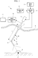
FIG. 1} FIG. 1 is a diagram showing the overall configuration of a medical system to which a control method according to a first embodiment of the present invention is applied. - {
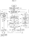
FIG. 2} FIG. 2 is a flowchart showing the control method inFIG. 1 . - {
FIG. 3} FIG. 3 is a diagram for describing the control method inFIG. 1 , showing a distal end section of an endoscope. - {
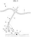
FIG. 4} FIG. 4 is a diagram for describing a medical-system control method according to a second embodiment of the present invention, showing a distal end section of an endoscope. - {
FIG. 5} FIG. 5 is a flowchart showing the control method inFIG. 4 . - {
FIG. 6} FIG. 6(a) is a diagram showing a distal end section of an endoscope, andFIG. 6(b) is a diagram showing a movable range of joints in a first modification of the control method inFIG. 4 . - {
FIG. 7} FIG. 7(a) is a diagram showing a distal end section of an endoscope, andFIG. 7(b) is a diagram showing a movable range of joints in a second modification of a control method inFIG. 4 . - {
FIG. 8} FIG. 8(a) is a diagram showing a distal end section of an endoscope, andFIG. 8(b) is a diagram showing a movable range of joints in a third modification of a control method inFIG. 4 . - {
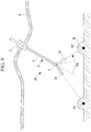
FIG. 9} FIG. 9 is a diagram for describing a medical-system control method according to a third embodiment of the present invention, showing a distal end section of an endoscope. - {
FIG. 10} FIG. 10 is a flowchart showing the control method inFIG. 9 . - A control method, according to a first embodiment of the present invention, for a
medical system 1 will be described below with reference to the drawings. - The control method according to this embodiment is applied to the
medical system 1 shown inFIG. 1 . - As shown in
FIG. 1 , thismedical system 1 includes atrocar 2 disposed through body surface tissue A; arigid endoscope 3 inserted through thetrocar 2; anoperation unit 6 for manually instructing the swivel angle of a joint (bendable section) 5 provided at a distal end of aninsertion section 4 of theendoscope 3; aninput unit 7 that sets the coordinates of a reference point P, serving as the reference for the part to be observed, such as an affected part B, in the body and instructs switching of the control state; adriving unit 8 for driving thejoint 5; acontrol unit 9 for controlling thedriving unit 8; animage processing unit 10 for generating an image from a signal acquired by theendoscope 3; and amonitor 11 for displaying the image formed by theimage processing unit 10. - The
trocar 2 is provided with sensors (not shown) for detecting the insertion amount I1, in the longitudinal axial direction, of theinsertion section 4 of theendoscope 3 and the inclination angle I2 of the longitudinal axis with respect to the vertical line. - In this embodiment, the
endoscope 3 has asingle joint 5. Thejoint 5 is provided at an end of therigid insertion section 4 and changes the angle of the longitudinal axis of adistal end section 3a relative to the longitudinal axis of theinsertion section 4. - On the basis of the instruction signal from the
operation unit 6, thecontrol unit 9 controls thedriving unit 8 by using a first control state, in which thedriving unit 8 is driven so as to cause the joint 5 to swivel in accordance with the instruction signal, and a second control (cooperative control) state, in which thejoint 5 is caused to swivel such that the longitudinal axis of thedistal end section 3a passes through the preset reference point P. Thecontrol unit 9 also implements a third control state for switching from the first control state to the second control state when receiving, from theinput unit 7, a switching instruction for switching from the first control state to the second control state. - Next, the control method, according to this embodiment, for the
medical system 1 will be described with reference toFIGS. 2 and3 . - As shown in
FIG. 2 , in the control method according to this embodiment, in a state in which the first control state is selected (step S1), when an operator operates theoperation unit 6 while observing the image acquired by theendoscope 3, displayed on themonitor 11, a final target angle θg of thejoint 5 corresponding to the operation amount given by manual operation via theoperation unit 6 is calculated (step S2), and a flag i is set to zero (step S3). Then, the final target angle θg is set also as a target angle θref of the joint 5 (step S4), and thedriving unit 8 is driven such that thejoint 5 forms the target angle θref (step S5). Unless a switching instruction is input, the process from step S2 to step S5 is repeated, so that the first control state is maintained. - Next, when the operator inputs a switching instruction for switching to the second control state via the input unit 7 (steps S6 and S7), first, the operator is prompted to designate the coordinates of the reference point P. When the operator designates the reference point P for specifying the affected part B or the like on the image displayed on the monitor 11 (step S8), the coordinate values of the designated reference point P is stored (step S9). Thereafter, the flag i is set to 1 (step S10). Note that the coordinates of the reference point P may be stored in advance. In such a case, steps S8 and S9 are omitted.
- Then, from the stored coordinate values of the reference point P, the final target angle θg is calculated (step S11). The final target angle θg is calculated in the following manner.
- Specifically, because the coordinates of the
joint 5 provided at the distal end of theinsertion section 4 are calculated from the insertion amount I1 and the inclination angle I2 of therigid insertion section 4, which are detected by the sensors provided on thetrocar 2, the angle formed between a line segment connecting the coordinates of thetrocar 2 and the coordinates of the joint 5 (i.e., the longitudinal axis of the insertion section 4) and a line segment connecting the coordinates of thejoint 5 and the coordinates of the reference point P (i.e., the longitudinal axis of thedistal end section 3a) is calculated as the final target angle θg. - This final target angle θg indicates the swivel angle of the
joint 5 when the reference point P is located on the optical axis of an image-capturing optical system, provided at a distal end of thedistal end section 3a, of theendoscope 3, and theendoscope 3 directly faces the reference point P. - Thereafter, whether or not the switching instruction for switching to the second control state has just been input is determined on the basis of whether or not the flag i is 1 (step S12), and, if the flag i is 1, the third control state is implemented.
- In the third control state, first, the difference between the final target angle θg of the
joint 5 and a current angle θe, |θg - θe|, is calculated (step S13), and it is determined whether or not the difference |θg - θe| is less than or equal to a predetermined threshold θth (step S14). If, as a result of the determination, the difference |θg - θe| is greater than the threshold θth, an angle obtained by adding a minute angle Δθ, which is smaller than the threshold θth, to the current angle is set as the target angle θref (step S15), and the process from step S5 is repeated. Herein, for example, a constant that is sufficiently smaller than the threshold θth may be set as the minute angle Δθ. - If, as a result of the determination, the difference Δθ is less than or equal to the threshold θth, the flag i is changed to 2 (step S16), and then the process from step S4 is repeated. By doing so, thereafter, the second control state, in which the
joint 5 is driven so as to follow the coordinate values of the reference point P, is implemented. - Specifically, with the control method, according to this embodiment, for the
medical system 1, when the first control state, in which thejoint 5 is driven by the drivingunit 8 according to the operation amount given by manual operation, is switched to the second control state, in which the reference point P is set, and the joint 5 is automatically driven by the drivingunit 8 so as to follow the reference point P, if the difference between the current angle θe and the final target angle θg, |θg - θe|, is greater than the predetermined threshold θth, the control state is not directly switched. Hence, it is possible to prevent a drastic change of the image acquired by theendoscope 3, as in the case where the control state is directly switched. - Before the first control state is switched to the second control state, the third control state, in which the target angle θref shifted from the current angle θe by the minute angle Δθ is set and the joint 5 is bent, is implemented once. Hence, there is an advantage in that it is possible to gradually change the image displayed on the
monitor 11, preventing the operator from losing sight of the affected part B or feeling a sense of incongruity. - In this embodiment, although a constant that is sufficiently smaller than the threshold θth is set as the minute angle Δθ, instead, a value obtained by multiplying the difference between the final target angle θg and the current angle θe, |θg - θe|, by 1/n (n is an integer greater than 2) may be set as the minute angle Δθ. By doing so, it is possible to set the minute angle Δθ that is proportional to the magnitude of the difference |θg - θe| and to drive the joint 5 at a higher speed when the difference |θg - θe| is large and at a lower speed when the difference |θg - θe| is small.
- Furthermore, when the insertion amount I1 and the inclination angle I2 of the
insertion section 4 are changed by operating theendoscope 3 while the third control state is implemented, a value smaller than the threshold θth that is proportional to the amount of movement ΔP thereof may be set as the minute angle Δθ. By doing so, it is possible to drive the joint 5 at a higher speed when the amount of movement ΔP of theinsertion section 4 is large and at a lower speed when the amount of movement ΔP of theinsertion section 4 is small. Herein, the amount of movement ΔP of theinsertion section 4 may be any one of the insertion amount I1, the inclination angle I2, and the magnitude of the vector of their composition. - Specifically, when the
insertion section 4 is advanced or retracted (a change in the insertion amount I1) or tilted (a change in the inclination angle I2) during switching from the first control state, in which manual control is performed, to the second control state, in which automatic control is performed, the target angle θref is updated according to the operation. Thus, it is possible to gradually bring the control state toward an ideal state achieved in the second control state and to more naturally switch the control state. - Next, a control method, according to a second embodiment of the present invention, for a
medical system 20 will be described below with reference to the drawings. - In the description of this embodiment, the configurations common to those of the control method, according to the above-described first embodiment, for the
medical system 1 will be denoted by the same reference signs, and descriptions thereof will be omitted. - The control method according to this embodiment is applied to the
medical system 20, shown inFIG. 4 , that includes theendoscope 3 having twojoints insertion section 4. - Also regarding the movement of these two
joints operation unit 6, thecontrol unit 9 implements the first control state, in which thedriving unit 8 is driven so as to cause thejoints driving unit 8 is driven so as to cause thejoints distal end section 3a passes through the preset reference point P. - More specifically, in the second control state, first, a swivel angle θ1, at which the preset reference point P is located on the longitudinal axis of the
distal end section 3a when only the joint 22 on the proximal end side is swiveled with the swivel angle of the joint 21 on the distal end side being set to zero (a state in which the portion between the joint 22 on the proximal end side and the distal end is straight), is obtained, and half of this swivel angle θ1 is set as a final target angle θg2 of the joint 22 on the proximal end side. Next, a swivel angle at which the preset reference point P is located on the longitudinal axis of thedistal end section 3a when only the joint 21 on the distal end side is swiveled with the joint 22 on the proximal end side being swiveled by the final target angle θg2 is obtained, and this swivel angle is set as the final target angle θg1 of the joint 21 on the distal end side. In the second control state, thecontrol unit 9 controls the drivingunit 8, which causes the twojoints - Furthermore, in the control method, according to this embodiment, for the
medical system 20, as shown inFIG. 5 , in the first control state, the final target angles θg1 and θg2 of thejoints operation unit 6 are calculated (step S20), the flag i is set to zero (step S3), the final target angles θg1 and θg2 are set also as target angles θref1 and θref2 of thejoints 21 and 22 (step S21), and thedriving unit 8 is driven such that thejoints - Next, when the operator inputs a switching instruction for switching from the first control state to the second control state (steps S6 and S7), and the coordinates of the reference point P are designated and stored (step S8 and S9), the final target angles θg1 and θg2 are calculated (step S22), and the distance, d, between the distal end of the
endoscope 3 and the reference point P when the final target angles θg1 and θg2 are achieved is calculated (step S23). Then, it is determined whether or not the calculated distance d is greater than a predetermined threshold dth (step S24). - When the distance d is greater than the threshold dth, the difference between the final target angle θg2 of the joint 22 on the proximal end side and a current angle θe2, |θg2 - θe2|, is calculated (step S25), and it is determined whether or not the difference |θg2 - θe2| is less than or equal to the predetermined threshold θth (step S26).
- If, as a result of the determination, the difference |θg2 - θe2| is greater than the threshold θth, an angle obtained by adding a minute angle Δθ2, which is smaller than the threshold θth, to the current angle θe2 is set as the target angle θref2, the target angle θref1 of the joint 21 on the distal end side when the joint 22 on the proximal end side moves by the target angle θref2 is calculated (step S27), and the process from step S5 is repeated.
- If, as a result of the determination, the difference |θg2 - θe2| is less than or equal to the threshold θth, the process from step S21 is repeated.
- On the other hand, when the calculated distance d is small, the calculated distance d is set to be equal to the threshold dth (step S28). Then, actuation of the
joints insertion section 4 to change the insertion amount I1 or the inclination angle I2 (step S29). That is, the process from step S22 is repeated. Then, after the operator operates theinsertion section 4, new final target angles θg1 and θg2 are calculated (step S22), and, when the distance d calculated on the basis of the new final target angles θg1 and θg2 is greater than the threshold dth, the operation from step S25 is performed. - The thus-configured control method, according to this embodiment, for the
medical system 20 has an advantage that, when the first control state, in which manual control is performed, is switched to the second control state, in which automatic control is performed, if the distance d between the distal end and the reference point P when the control state is switched to the second control state is smaller than the threshold dth, the switching to the second control state is stopped to prevent the end of theinsertion section 3 from getting too close to the affected part B. - Furthermore, as in the first embodiment, when the distance d is greater than the threshold dth, the
joints monitor 11 is gradually changed, which leads to an advantage in that the operator does not lose sight of the affected part B or does not feel a sense of incongruity. - Note that, in this embodiment, although the swivel angle θ1 at which the preset reference point P is located on the longitudinal axis of the
distal end section 3a when only the joint 22 on the proximal end side is swiveled is obtained, and half of this swivel angle θ1 is set as the final target angle θg2 of the joint 22 on the proximal end side, the configuration is not limited thereto. The final target angle θg2 may be calculated by multiplying the swivel angle θ1 by a set ratio K. - For example, when 1/3 is employed as the ratio K, as shown in
FIGS. 6(a) and 6(b) , a movable range C1 results, in which the joint 22 on the proximal end side moves by a small amount and the joint 21 on the distal end side moves by a large amount. This is suitable for observation in a small space, in which the distal end can be moved by a large amount, even with a narrow entrance. - Furthermore, in the above-described method in which 1/2 is employed as the ratio K, as shown in
FIGS. 7(a) and 7(b) , a movable range C2 results, in which the joint 21 on the distal end side and the joint 22 on the proximal end side are moved by equal amounts. This allows standard observation to be performed. - Furthermore, when 2/3 is employed as the ratio K, as shown in
FIGS. 8(a) and 8(b) , a movable range C3 results, in which the joint 22 on the proximal end side moves by a large amount. Because the joint 22 on the proximal end side moves by a large amount in the wide movable range C3, this is suitable for observing a large space in detail. - A plurality of these ratios K may be registered, and one of them may be selected according to the type of observation.
- Next, a control method, according to a third embodiment of the present invention, for a
medical system 30 will be described below with reference to the drawings. - In the description of this embodiment, the configurations common to those of the control method, according to the above-described first embodiment, for the
medical system 1 will be denoted by the same reference signs, and descriptions thereof will be omitted. - The control method, according to this embodiment, for the
medical system 30 differs from that according to the first embodiment in that it is used when a first control state in which automatic control is performed is switched to a second control state in which automatic control is performed, whereas the control method according to the first embodiment is used when the first control state in which manual control is performed is switched to the second control state in which automatic control is performed. - Specifically, in the control method according to this embodiment, as shown in
FIG. 9 , the coordinates of two or more different reference points P1 and P2 are stored, and a third control state is implemented when the first control state, in which thejoint 5 is driven so as to follow one reference point P1 even when the insertion amount I1 or the inclination angle I2 of theinsertion section 4 is changed, is switched to the second control state, in which thejoint 5 is driven so as to follow another reference point P2. - In this case too, as shown in
FIG. 10 , similarly to the first embodiment, in the first control state (step S1), one reference point P1 is selected (step S30), and the final target angle θg is calculated from the stored coordinate values of the one reference point P1 (step S31). Thereafter, whether or not the switching instruction for switching to the second control state has just been input is determined on the basis of whether or not the flag i is 1 (step S12). If the flag i is 1, the reference point is switched to the reference point P2 (step S32), and the third control state is implemented. - In the third control state, first, the difference between the final target angle θg of the joint 5 and the current angle θe, |θg - θe|, is calculated (step S13), and it is determined whether or not the difference |θg - θe| is less than or equal to the predetermined threshold θth (step S14).
- If, as a result of the determination, the difference |θg - θe| is greater than the threshold θth, an angle obtained by adding a minute angle Δθ, which is smaller than the threshold θth, to the current angle θe is set as the target angle θref (step S15), and the process from step S5 is repeated.
- If, as a result of the determination, the difference |θg - θe| is less than or equal to the threshold θth, after the flag i is changed to 2 (step S16), the final target angle θg is set as the target angle θref, and the
driving unit 8 is driven to cause the joint 5 to swivel to the final target angle θg. In this way, the control state is switched to the second control state. - With the control method according to this embodiment, also when the first control state, in which the
joint 5 is controlled so as to follow one reference point P1, is switched to the second control state, in which thejoint 5 is controlled so as to follow another reference point P2, an angle moved by a minute angle Δθ from the current angle θe is set as the target angle θref and the joint 5 is swiveled. Thus, there is an advantage that it is possible to gradually change the image displayed on themonitor 11, preventing the operator from losing sight of the affected part B or feeling a sense of incongruity. -
- d
- distance
- dth
- distance threshold
- I1
- insertion amount
- I2
- inclination angle
- P, P1, P2
- reference point
- θe, θe2
- current angle
- θg, θg1, θg2
- final target angle
- θref, θref1, θref2
- target angle
- θth
- threshold
- Δθ
- minute angle
- S2, S20
- final-target-angle calculation step
- S5
- driving step
- S6
- switching-instruction step
- S13
- angle-difference calculation step
- S15
- target calculation step
- S29
- detection step
- 1, 20, 30
- medical system
- 2
- trocar
- 3
- endoscope
- 4
- insertion section
- 5, 21, 22
- joint (bendable section)
Claims (7)
- A medical-system control method, in which, in a medical system having an insertion section of an endoscope inserted into the body through a through-hole in a trocar, two different control states of a bendable section provided at a distal end of the insertion section are switched, the method comprising:a switching-instruction step in which a switching instruction for switching the control state is received;an angle-difference calculation step in which the angle difference between a current angle of the bendable section when the switching instruction is received in the switching-instruction step and a final target angle of the bendable section in the control state after being switched is calculated;a target calculation step in which, when the angle difference calculated in the angle-difference calculation step exceeds a predetermined threshold, a minute angle, which is smaller than the threshold, is added to the current angle to calculate a target angle, and in which, when the angle difference is less than or equal to the threshold, the angle difference is added to the current angle to calculate the target angle; anda driving step in which the bendable section is driven to the target angle calculated in the target calculation step.
- The medical-system control method according to Claim 1, wherein the minute angle is an angle obtained by multiplying the angle difference by 1/n (n is an integer greater than 2).
- The medical-system control method according to Claim 1 or 2, further comprising:a detection step in which the inclination angle of a longitudinal axis of the insertion section through the trocar and the insertion amount thereof in the longitudinal axial direction are detected; anda final-target-angle calculation step in which the final target angle is calculated on the basis of the coordinate values of a specific reference point in the control state after being switched, the insertion amount, and the inclination angle.
- The medical-system control method according to Claim 3, wherein, in the control state before being switched, the bendable section is bent according to a manual instruction.
- The medical-system control method according to Claim 3, wherein, in the control state before being switched, the bendable section is bent on the basis of the coordinate values of another reference point, the insertion amount, and the inclination angle.
- The medical-system control method according to Claim 4, wherein the distance between a distal end of the bendable section and the reference point in the control state after being switched is calculated after the switching-instruction step, and, when the distance is smaller than a distance threshold, control is performed such that the distal end of the bendable section is not moved.
- The medical-system control method according to any one of Claims 1 to 6, wherein
the insertion section includes a plurality of bendable sections,
a plurality of ratios of the bending amounts of the bendable sections are stored, and
the ratios of the bending amounts are changed before and after switching the control state.
Applications Claiming Priority (2)
| Application Number | Priority Date | Filing Date | Title |
|---|---|---|---|
| JP2014035655A JP6278737B2 (en) | 2014-02-26 | 2014-02-26 | Method of operating a medical system |
| PCT/JP2015/052151 WO2015129368A1 (en) | 2014-02-26 | 2015-01-27 | Control method for medical system |
Publications (2)
| Publication Number | Publication Date |
|---|---|
| EP3114980A1 true EP3114980A1 (en) | 2017-01-11 |
| EP3114980A4 EP3114980A4 (en) | 2017-12-13 |
Family
ID=54008694
Family Applications (1)
| Application Number | Title | Priority Date | Filing Date |
|---|---|---|---|
| EP15755552.5A Withdrawn EP3114980A4 (en) | 2014-02-26 | 2015-01-27 | Control method for medical system |
Country Status (5)
| Country | Link |
|---|---|
| US (1) | US10588485B2 (en) |
| EP (1) | EP3114980A4 (en) |
| JP (1) | JP6278737B2 (en) |
| CN (1) | CN106028902B (en) |
| WO (1) | WO2015129368A1 (en) |
Cited By (1)
| Publication number | Priority date | Publication date | Assignee | Title |
|---|---|---|---|---|
| EP3305161A4 (en) * | 2015-05-28 | 2019-01-09 | Olympus Corporation | Endoscope system |
Families Citing this family (12)
| Publication number | Priority date | Publication date | Assignee | Title |
|---|---|---|---|---|
| US8888789B2 (en) | 2009-09-23 | 2014-11-18 | Intuitive Surgical Operations, Inc. | Curved cannula surgical system control |
| US8623028B2 (en) | 2009-09-23 | 2014-01-07 | Intuitive Surgical Operations, Inc. | Surgical port feature |
| US20110071541A1 (en) | 2009-09-23 | 2011-03-24 | Intuitive Surgical, Inc. | Curved cannula |
| US9949615B2 (en) * | 2011-09-21 | 2018-04-24 | Boston Scientific Scimed, Inc. | Systems and methods for preventing laser fiber misfiring within endoscopic access devices |
| WO2017070610A1 (en) * | 2015-10-21 | 2017-04-27 | Inscopix, Inc. | Implantable optical probes and systems and methods for implantation of optical probes |
| JP7022400B2 (en) * | 2017-01-13 | 2022-02-18 | 朝日サージカルロボティクス株式会社 | Surgical support device, its control method, program and surgical support system |
| WO2019087269A1 (en) * | 2017-10-31 | 2019-05-09 | オリンパス株式会社 | Endoscope system |
| US11559298B2 (en) * | 2018-07-16 | 2023-01-24 | Cilag Gmbh International | Surgical visualization of multiple targets |
| US11571107B2 (en) * | 2019-03-25 | 2023-02-07 | Karl Storz Imaging, Inc. | Automated endoscopic device control systems |
| US20210196319A1 (en) * | 2019-12-29 | 2021-07-01 | Biosense Webster (Israel) Ltd | Trocar with internal camera providing tilted view angle |
| US20240155241A1 (en) * | 2021-06-21 | 2024-05-09 | Sony Group Corporation | Medical observation system, information processing device, and information processing method |
| US20250113981A1 (en) * | 2023-10-04 | 2025-04-10 | Patrick A. MASSEY | Endoscopic camera system with adjustable field of view |
Family Cites Families (12)
| Publication number | Priority date | Publication date | Assignee | Title |
|---|---|---|---|---|
| JPH04129695A (en) * | 1990-09-17 | 1992-04-30 | Olympus Optical Co Ltd | Curvature operation device |
| JP3012341B2 (en) * | 1990-12-25 | 2000-02-21 | オリンパス光学工業株式会社 | Endoscope device |
| US6331181B1 (en) | 1998-12-08 | 2001-12-18 | Intuitive Surgical, Inc. | Surgical robotic tools, data architecture, and use |
| AU2003264354A1 (en) * | 2002-08-30 | 2004-04-30 | Olympus Corporation | Medical treatment system, endoscope system, endoscope insert operation program, and endoscope device |
| US7841980B2 (en) | 2006-05-11 | 2010-11-30 | Olympus Medical Systems Corp. | Treatment system, trocar, treatment method and calibration method |
| JP2008110071A (en) * | 2006-10-30 | 2008-05-15 | Olympus Corp | Curving section structure of endoscope |
| JP5237608B2 (en) * | 2007-10-25 | 2013-07-17 | オリンパスメディカルシステムズ株式会社 | Medical equipment |
| WO2009069395A1 (en) | 2007-11-29 | 2009-06-04 | Olympus Medical Systems Corp. | Endoscope curve control device and endoscope system |
| WO2012039199A1 (en) * | 2010-09-23 | 2012-03-29 | オリンパスメディカルシステムズ株式会社 | Bendable catheter |
| EP2583616B1 (en) | 2011-03-29 | 2015-04-01 | Olympus Medical Systems Corp. | Endoscope |
| JP5841366B2 (en) * | 2011-07-14 | 2016-01-13 | オリンパス株式会社 | Medical equipment |
| JP2014004310A (en) * | 2012-05-31 | 2014-01-16 | Canon Inc | Medical instrument |
-
2014
- 2014-02-26 JP JP2014035655A patent/JP6278737B2/en active Active
-
2015
- 2015-01-27 EP EP15755552.5A patent/EP3114980A4/en not_active Withdrawn
- 2015-01-27 WO PCT/JP2015/052151 patent/WO2015129368A1/en not_active Ceased
- 2015-01-27 CN CN201580009250.4A patent/CN106028902B/en active Active
-
2016
- 2016-08-19 US US15/241,629 patent/US10588485B2/en active Active
Cited By (2)
| Publication number | Priority date | Publication date | Assignee | Title |
|---|---|---|---|---|
| EP3305161A4 (en) * | 2015-05-28 | 2019-01-09 | Olympus Corporation | Endoscope system |
| US10694928B2 (en) | 2015-05-28 | 2020-06-30 | Olympus Corporation | Endoscope system |
Also Published As
| Publication number | Publication date |
|---|---|
| US20170042406A1 (en) | 2017-02-16 |
| WO2015129368A1 (en) | 2015-09-03 |
| JP2015159891A (en) | 2015-09-07 |
| EP3114980A4 (en) | 2017-12-13 |
| CN106028902A (en) | 2016-10-12 |
| JP6278737B2 (en) | 2018-02-14 |
| US10588485B2 (en) | 2020-03-17 |
| CN106028902B (en) | 2018-09-28 |
Similar Documents
| Publication | Publication Date | Title |
|---|---|---|
| EP3114980A1 (en) | Control method for medical system | |
| US20250255684A1 (en) | Systems and methods for onscreen identification of instruments in a teleoperational medical system | |
| EP2925250B1 (en) | Operation support system | |
| EP3305161A1 (en) | Endoscope system | |
| US20180092700A1 (en) | Systems and Methods for Rendering Onscreen Identification of Instruments in a Teleoperational Medical System | |
| EP3415071A1 (en) | Endoscope system | |
| EP3173047B1 (en) | Treatment device and treatment device system | |
| US10123681B2 (en) | Endoscope insertion shape observation apparatus having a controller to drive bending of insertion portion of endoscope | |
| US9974620B2 (en) | Manipulator system, and medical system | |
| JP2015154873A (en) | endoscope system | |
| EP2997879B1 (en) | Master-slave system | |
| EP2862497A1 (en) | Manipulator system | |
| WO2015005072A1 (en) | Surgical assistance robot | |
| Reilink et al. | Image-based hysteresis reduction for the control of flexible endoscopic instruments | |
| EP3263063A1 (en) | Manipulator system | |
| US10959787B2 (en) | Medical manipulator system | |
| US10251536B2 (en) | Medical instrument, medical system, and mode transition method for medical instruments | |
| WO2017104022A1 (en) | Operating method for medical manipulator |
Legal Events
| Date | Code | Title | Description |
|---|---|---|---|
| STAA | Information on the status of an ep patent application or granted ep patent |
Free format text: STATUS: THE INTERNATIONAL PUBLICATION HAS BEEN MADE |
|
| PUAI | Public reference made under article 153(3) epc to a published international application that has entered the european phase |
Free format text: ORIGINAL CODE: 0009012 |
|
| STAA | Information on the status of an ep patent application or granted ep patent |
Free format text: STATUS: REQUEST FOR EXAMINATION WAS MADE |
|
| 17P | Request for examination filed |
Effective date: 20160923 |
|
| AK | Designated contracting states |
Kind code of ref document: A1 Designated state(s): AL AT BE BG CH CY CZ DE DK EE ES FI FR GB GR HR HU IE IS IT LI LT LU LV MC MK MT NL NO PL PT RO RS SE SI SK SM TR |
|
| AX | Request for extension of the european patent |
Extension state: BA ME |
|
| DAX | Request for extension of the european patent (deleted) | ||
| A4 | Supplementary search report drawn up and despatched |
Effective date: 20171113 |
|
| RIC1 | Information provided on ipc code assigned before grant |
Ipc: A61B 1/00 20060101AFI20171107BHEP Ipc: G02B 23/24 20060101ALI20171107BHEP |
|
| STAA | Information on the status of an ep patent application or granted ep patent |
Free format text: STATUS: EXAMINATION IS IN PROGRESS |
|
| 17Q | First examination report despatched |
Effective date: 20190409 |
|
| STAA | Information on the status of an ep patent application or granted ep patent |
Free format text: STATUS: THE APPLICATION IS DEEMED TO BE WITHDRAWN |
|
| 18D | Application deemed to be withdrawn |
Effective date: 20190820 |