EP3114945A1 - Disassembly device and disassembly method for smokers' articles - Google Patents
Disassembly device and disassembly method for smokers' articles Download PDFInfo
- Publication number
- EP3114945A1 EP3114945A1 EP16177629.9A EP16177629A EP3114945A1 EP 3114945 A1 EP3114945 A1 EP 3114945A1 EP 16177629 A EP16177629 A EP 16177629A EP 3114945 A1 EP3114945 A1 EP 3114945A1
- Authority
- EP
- European Patent Office
- Prior art keywords
- smokers
- article
- feed path
- separating
- articles
- Prior art date
- Legal status (The legal status is an assumption and is not a legal conclusion. Google has not performed a legal analysis and makes no representation as to the accuracy of the status listed.)
- Granted
Links
Images




Classifications
-
- A—HUMAN NECESSITIES
- A24—TOBACCO; CIGARS; CIGARETTES; SIMULATED SMOKING DEVICES; SMOKERS' REQUISITES
- A24C—MACHINES FOR MAKING CIGARS OR CIGARETTES
- A24C5/00—Making cigarettes; Making tipping materials for, or attaching filters or mouthpieces to, cigars or cigarettes
- A24C5/36—Removing papers or other parts from defective cigarettes
Definitions
- This invention relates to a disassembly device and a disassembly method for smokers' articles.
- This invention is thus applicable in particular in the tobacco industry, especially in machines for making cigarettes or the like and, more precisely, for recovering and/or disposing of defective products.
- Cigarettes found to be defective are rejected at specific expulsion stations, thus becoming reject products, and are collected, usually in specific containers, and then transferred to specific machines especially designed to recover the tobacco from them.
- the defective cigarettes are crushed or the paper is cut lengthways by a blade, and the different cigarette parts (filter, paper and tobacco) are separated.
- the filters and paper are scrapped, whereas the tobacco is recovered and then re-used in cigarette making machines.
- flavoured cigarettes where the filter is, in many cases, a composite filter and contains capsules or other flavouring elements, it is usually desirable to recover these elements.
- the step of mechanically pushing the capsule is also risky because the capsule might break, causing its contents to spill out onto the conveyor, thus spoiling the quality of subsequent products, especially of the tobacco they contain.
- the basic technical purpose of this invention is to provide a disassembly device and a disassembly method for smokers' article which overcome the above mentioned disadvantages of the prior art.
- the aim of this invention is to provide a disassembly device and a disassembly method for smokers' article which are highly reliable and easy to implement.
- the aim of this invention is to provide a disassembly device and a disassembly method for smokers' article which are fast and precise. These aims are achieved by a disassembly device according to one or more of the accompanying claims from 1 to 16 and by a disassembly method for smokers' articles according to one or more of the appended claims from 17 to 25.
- a device for the disassembly of smokers' articles comprising feeding means configured to move the smokers' articles along a feed path, cutting means operating along the feed path and configured to make at least one incision on each smokers' article, where the incision defines a separating line between a first half-part and a second half-part of the smokers' article, and separating means operatively located downstream of the cutting means along the feed path and configured to separate the first half-part from the second half-part of the smokers' article.
- the separating line defined by the separating means is located at a discrete element located inside the smokers' article in such a way that the discrete element itself is partly inside the first half-part and partly inside the second half-part, that is to say, placed astride thereof.
- the separating means comprise at least a first and a second gripping means, opposite each other and each configured to pick up the first or the second half-part of the smokers' article, respectively and to move them away from each other.
- the two half-parts are thus moved apart, allowing the discrete element to be released without being touched by mechanical parts.
- the cutting means have at least one pair of opposing blades which are spaced from each other in such a way that the feed path is interposed between the two blades in order to make two longitudinal incisions facing each other.
- the movement of the smokers' articles is not interrupted and the speed of disposal is increased.
- the separating means comprise a pair of suction units configured to retain and release the first half-part and the second half-part, respectively.
- the pair of suction units comprises two drums which are, rotatable about parallel axes transversal to the feed path and which are mounted in such a way that their respective peripheries are substantially tangent at the feed path, and where both of the peripheries are provided with a circumferential suction channel.
- the device can also be used to disassemble the cigarette portion containing the tobacco, where the paper wrapping is cut and removed by suction while the tobacco is recovered.
- the numeral 1 denotes in its entirety a device for the disassembly of smokers' articles according to this invention.
- Each cigarette (or smokers' article “S") extends along its main axis "A" of extension and comprises at least a main portion “S1” and a filter “F” positioned in series along the axis "A".
- the main portion "S1" is basically a paper wrapper containing a predetermined quantity of tobacco.
- the filter "F" comprises a wrapper containing a piece of filter material.
- the filter houses a discrete element "B", preferably containing a flavouring fluid for the cigarette.
- the discrete element "B" is a capsule, preferably made of plastic material and containing a flavouring such as, for example, menthol or the like.
- the disassembly device 1 is preferably associated with a machine 100 for making smokers' articles, in particular a filter tip attachment machine, that is to say, a machine configured to combine (in essentially known manner) a filter "F" with the corresponding main portion "S1" of each cigarette. More specifically, the disassembly device 1 is operatively connected to a line which recovers/rejects the material and which, following a quality inspection, diverts defective cigarettes from the forming and packing path.
- the disassembly device 1 comprises feeding means 2 configured to move the smokers' articles "S" along a feed path "P";
- the feeding means 2 are associated with the machine 100 and, in particular, with the rejection/recovery line.
- the feeding means 2 are configured to move the smokers' articles “S” in such a way that the feed path "P" is parallel to the axis "A".
- the feed path "P" is preferably, a longitudinal feed path.
- the feeding means 2 comprise at least one conveyor 3 extending along a feed path "P" between its first end and its second end 3a.
- the conveyor 3 comprises at least one pair of opposed, facing belts 4 respectively defining a first and a second means for feeding the smokers' articles "S".
- the belts 4 are facing and spaced from each other by an amount such as to allow each smokers' article "S" to pass in between while remaining in contact with both of them in order to be moved forward.
- the two belts 4 define between them a channel whose transverse cross section is substantially equal to that of the smokers' article "S".
- the space between the two belts 4 at least partly defines a gap providing lateral access to the feed path "P", that is, to the smokers' articles "S".
- the two belts 4 are located at the sides of the feed path "P", that is, at the sides of the smokers' articles "S", thus defining an upper access gap and a lower access gap.
- the disassembly device 1 Operatively downstream of (or at) the feeding means 2, the disassembly device 1 further comprises cutting means 5 which operate along the feed path "P"., The cutting means 5 are configured to make at least one incision 50 on each smokers' article "S”.
- the incision 50 defines a separating line between a first half-part 51 and a second half-part 52 of the smokers' article "S".
- the cutting means 5 are configured to make a cut in the smokers' article "S" which does not pass right through the latter and which facilitates subsequent separation of the two half-parts 51, 52.
- the cutting means 5 comprise at least one blade 6 oriented in parallel with the central axis "A" of the smokers' article "S".
- the blade 6 is oriented in parallel with the feed path "P". That means the incision 50 is longitudinal.
- the cutting means 5 comprise a pair of opposed blades 6 which make two parallel incisions 50 delimiting the first half-part 51 and the second half-part 52 of the smokers' article "S".
- the blades 6 are opposed and spaced in such a way that the feed path "P" is interposed between them in order to make two longitudinal incisions 50 facing each other.
- the two blades 6 are substantially co-planar and located on opposite sides of the feed path "P".
- the blades 6 are located at the lateral access gaps defined by the feeding means 2 and, more preferably, at the upper and lower access gap.
- the cutting blades 6 are defined by rotatable cutting discs 6a, where the circumferential peripheral portion of each disc defines the cutting edge of the blade.
- the two cutting discs 6a are mounted on the same forked frame 7 with which both discs are rotatably associated.
- An actuator (not illustrated) and transmission means 8, interposed between the actuator and the discs 6a, are preferably also provided with reference to the embodiment illustrated in Figures 1-4 , where the smokers' articles “S” are preferably filters “F” and contain at least one discrete element "B", the cutting means 5 are configured to make the separating line at the discrete element "B".
- the cutting means 5, that is to say, the blades 6, are positioned along a line running through the centre of the feed path "P". That way, the discrete element "B”, or flavoured capsule, is positioned astride of the two half-parts 51, 52.
- the discrete element "B" is positioned partly in the first half-part 51 and partly in the second half-part 52.
- the cutting means 5 are configured to make two (or more) incisions 50 in the smokers' article “S", in particular in the filter "T", each extending transversely to the axis, from the peripheral surface of the smokers' article “S” to an internal zone proximal to the discrete element "B".
- the incisions 50 are cut in such a way that each incision 50 reaches to the depth of the discrete element, preferably without interfering with it.
- the discrete element "B", or capsule is thus not involved in cutting operations and does not come into contact with mechanical parts, making disassembly, and as will become clearer as this description continues, recovery, more precise and reliable.
- the disassembly device 1 comprises separating means 9 operatively located downstream of the cutting means 5 along the feed path "P" and configured to separate the first half-part 51 from the second half-part 52 of the smokers' article "S".
- the separating means 9 comprise at least a first gripping means 10a and a second gripping means 10b, placed opposite each other.
- Each gripping means 10a, 10b is configured to pick up the first half-part 51 or the second half-part 52 of the smokers' article "S", respectively and to move them away from each other.
- the gripping means apply a mechanical action on the first and second half-parts 51 and 52.
- the two half-parts 51, 52 are separated in a precise and reliable manner.
- first and second gripping means 10a and 10b are oriented transversely to the cutting means 5.
- the gripping means 10a, 10b are configured to move the half-parts 51, 52 away from each other along a direction transverse to the incision 50 or to the incisions 50.
- the separating means 9 and the first and second half-parts 51 and 52 are gripped and moved transversely to a cutting plane which the blades 6 lie in.
- each gripping means 10a, 10b comprises a first disc 11 and a second disc 12, facing each other and rotatable about respective axes of rotation "R1 ", "R2".
- the axes of rotation "R1 ", “R2 are oriented in such a way that in a gripping zone “T", proximal to the feed path "P", the edges 11 a, 12a of the discs 11, 12 are close to each other so as to apply a gripping action on one side of the respective first half-part 51 or second half-part 52.
- the axes of rotation "R1 ", “R2" of the first disc 11 and of the second disc 12 are inclined to each other in such a way that, at least inside the gripping zone "T", the distance “d1” between the respective edges 11 a, 12a is smaller than the distance "d1” between the respective edges 11 a, 12a outside the gripping zone "T".
- the axes of rotation "R1 ", "R2" of the first disc 11 and of the second disc 12 of each gripping means are inclined to, and coplanar with, each other.
- the inclination is between 20° and 70°, preferably approximately 50°.
- each first disc 11 has a chamfered peripheral edge 11 a, where the chamfer faces the peripheral edge 12a of the corresponding second disc 12, which is also chamfered.
- the gripping means might be embodied by grippers or other clamping parts.
- the separating means 9 comprises a blowing unit 13 located at the gripping means 10a, 10b and configured to produce an air flow transversal to the feed path "P" to facilitate detachment, and hence separation, of the discrete element "B" from the first half-part 51 and/or from the second half-part 52.
- blowing unit 13 is located immediately downstream of the gripping zone "T" along the feed path "P".
- the blowing unit 13 comprises at least one blowing nozzle 13a located above the feed path "P" and directed towards the feed path "P", transversely thereto.
- the blowing nozzle 13a can produce an air flow which is substantially vertical (that is, predominantly vertical) directed from the top down in order to make it easier for the discrete element "B" to fall out.
- reclaiming means 14, located at the separating means 9, are preferably provided for receiving at least one discrete element "B" from inside the smokers' article "S".
- the reclaiming means 14 comprise a channel or collector located on the side of the feed path "P" opposite to the blowing unit 13.
- blowing nozzle 13a and the channel or collector 14a are located on opposite sides with reference to the feed path "P" of the smokers' articles "S".
- the separating means 9 comprise a pair of suction units 15 configured to retain and release the first half-part 51 and the second half-part 52, respectively.
- first and second half-parts 51 and 52 are not necessarily portions of filter “F” but preferably portions of paper wrapper of the main portion "S1" of the cigarette.
- the pair of suction units 15 comprises two drums 16, 17 which are, rotatable about parallel axes transversal to the feed path "P".
- the drums 16, 17 are mounted in such a way that their respective peripheries are substantially tangent at the feed path "P" and are both provided with a circumferential suction channel 16a, 17a.
- each drum 16, 17 is provided with a circumferential peripheral channel 16a, 17a defining a concavity facing towards the other drum.
- the circumferential channels meet at a gripping zone "T" in such a way as to define a gap whose cross section is substantially the same as that of the smokers' article "S".
- the two half-parts 51, 52 of the wrapping are held by the suction units 15 while the tobacco contained in between may be recovered.
- the embodiment discussed here also comprises collecting means 18, preferably operating by suction, for collecting the tobacco which is released when the two half-parts 51, 52 of the wrapping are separated.
- the collecting means 18 are preferably connected to a recovery channel (not illustrated) configured to transport the tobacco recovered to a feed station (also not illustrated) where the tobacco, not re-processed in any way and therefore suitable for making another cigarette is fed back into the machine.
- this invention also has for an object a method for the disassembly of a smokers' article "S", preferably, but not exclusively, implemented by a disassembly device according to the invention.
- the method according to this invention may be implemented by the disassembly device illustrated in Figures 1 to 4 or in Figure 5 .
- the method comprises an initial step of feeding a plurality of smokers' articles "S", each extending along its central axis "A”, in succession along a feed path "P".
- the feeding step is preferably carried out following a selecting and inspecting step where the defective smokers' articles "S" are detected and directed to the disassembly device.
- the feeding step is performed in a direction parallel to the central axis of the smokers' articles "S".
- the feed path "P" is parallel with the central axis "A" of the smokers' articles "S".
- the method comprises cutting each smokers' article "S" peripherally, that is, along a periphery thereof, in such a way as to make an incision 50 defining the aforementioned separating line between the first half-part 51 and the second half-part 52 of the smokers' article "S".
- the cutting step comprises making at least one longitudinal incision 50 substantially parallel to the central axis "A" of the smokers' article "S"..
- the cutting step comprises making two (or more) incisions 50 in the smokers' article "S", each extending transversely to the central axis "A", from the peripheral surface of the smokers' article “S” to an internal zone proximal to the discrete element "B".
- the incision 50 is made (or the incisions 50 are made) at the discrete element "B" itself.
- the incision or incisions 50 is/are made along the centre line of the smokers' article "S".
- the incisions 50 are cut in such a way that each incision 50 reaches to the depth of the discrete element, preferably without interfering with it.
- the discrete element "B", or capsule is thus not involved in cutting operations and does not come into contact with mechanical parts, making disassembly, and as will become clearer as this description continues, recovery, more precise and reliable.
- the cutting step is followed by a step of separating the first half-part 51 from the second half-part 52.
- this step is carried out to allow releasing the discrete element "B".
- the separating step comprises a substep, performed in a specific gripping zone "T", of picking up or gripping each half-part 51, 52.
- the half-parts 51, 52 are moved apart in order to allow the discrete element "B" to be released.
- the step of pneumatically pushing the discrete element away from the half-parts is also a step of pneumatically pushing the discrete element away from the half-parts, performed by a blowing unit or the like.
- the step of releasing the discrete element "B” is carried out by allowing the discrete element "B" to fall out.
- This embodiment comprises a step of recovering the discrete element "B" concurrently with, or immediately after, the separating step.
- the separating step comprises sucking the first half-part 51 and the second half-part 52 in opposite directions. This sucking action is preferably applied by means of suction cavities or drums similar to those described above.
- this embodiment comprises a suction step, concurrent with the separating step, to extract the tobacco from the smokers' article.
- the reclaimed tobacco is preferably returned through specific ducts into the process of forming new smokers' articles/cigarettes.
- the invention achieves the above mentioned aims and brings important advantages.
- a disassembly device in which the cutting blades divide each article into two half-parts, preferably longitudinal, which are then moved apart, allows the tobacco or the discrete elements to be recovered without being damaged by the blades or other mechanical parts.
- the gripping means which are preferably disc-shaped, makes it easier to complete the separating action initiated by the blades and thus facilitates releasing the discrete elements.
Landscapes
- Manufacturing Of Cigar And Cigarette Tobacco (AREA)
- Processing Of Solid Wastes (AREA)
Abstract
Description
- This invention relates to a disassembly device and a disassembly method for smokers' articles.
- This invention is thus applicable in particular in the tobacco industry, especially in machines for making cigarettes or the like and, more precisely, for recovering and/or disposing of defective products.
- In light of this, hereinafter in this description, reference is made, by way of example only and without losing in generality, to smokers' articles such as cigarettes.
- During the production of cigarettes, the total number of cigarettes made inevitably includes defective cigarettes among the cigarettes which meet accepted standards of quality. For this reason, cigarette making machines are equipped with numerous checking devices by which each cigarette is tested for conformity to specifications. In effect, it is necessary, for example, to check that every cigarette made contains the right quantity of tobacco, that there is enough tobacco at the end opposite the filter to make that end sufficiently compact to prevent the tobacco from falling out, that the paper wrapped around the tobacco is correctly glued and is not torn or stained, and so on.
- Cigarettes found to be defective are rejected at specific expulsion stations, thus becoming reject products, and are collected, usually in specific containers, and then transferred to specific machines especially designed to recover the tobacco from them.
- In these machines, the defective cigarettes are crushed or the paper is cut lengthways by a blade, and the different cigarette parts (filter, paper and tobacco) are separated. The filters and paper are scrapped, whereas the tobacco is recovered and then re-used in cigarette making machines.
- Moreover, in flavoured cigarettes, where the filter is, in many cases, a composite filter and contains capsules or other flavouring elements, it is usually desirable to recover these elements.
- Indeed, the cost of these elements is all but negligible and recovering them reduces waste.
- Recovering them is also very important for the purposes of waste disposal, where different types of waste are disposed of in different ways and it is desirable to separate the filter material from the chemical/biological substances inside the capsules.
- For these purposes, numerous disassembly devices, usually quite complex and expensive, are known in the prior art.
- One example of such devices is disclosed in document
EP2730182 , which describes a complex system for the disassembly of cigarettes, where the flavouring element (or capsule) located inside the filter is mechanically removed with the aid of a wheel provided with pushers which mechanically press the portion of filter left protruding from a previously cut piece of filter. Disadvantageously, this solution involves completely cutting the head of the filter tip, during which it is very likely that the flavouring element (or capsule) will either break or fall out and fail to be recovered. - Moreover, the step of mechanically pushing the capsule is also risky because the capsule might break, causing its contents to spill out onto the conveyor, thus spoiling the quality of subsequent products, especially of the tobacco they contain.
- Another example of a prior art device is disclosed in publication
EP2730184 , where the pushing means, previously described only generically, are described in more detail and comprise a wedge-shaped fork designed to be inserted transversely into the filter to push the capsule out of the filter whose "head" has been removed by the wedge-shaped portion. - A closer look at this structure reveals even more clearly the disadvantages of recovery systems of this kind, which are invasive and unreliable, especially in terms of the risk of damaging the flavouring element (or capsule).
- In this context, the basic technical purpose of this invention is to provide a disassembly device and a disassembly method for smokers' article which overcome the above mentioned disadvantages of the prior art.
- More specifically, the aim of this invention is to provide a disassembly device and a disassembly method for smokers' article which are highly reliable and easy to implement.
- More precisely, the aim of this invention is to provide a disassembly device and a disassembly method for smokers' article which are fast and precise. These aims are achieved by a disassembly device according to one or more of the accompanying claims from 1 to 16 and by a disassembly method for smokers' articles according to one or more of the appended claims from 17 to 25.
- More specifically, the above aims are achieved by a device for the disassembly of smokers' articles, comprising feeding means configured to move the smokers' articles along a feed path, cutting means operating along the feed path and configured to make at least one incision on each smokers' article, where the incision defines a separating line between a first half-part and a second half-part of the smokers' article, and separating means operatively located downstream of the cutting means along the feed path and configured to separate the first half-part from the second half-part of the smokers' article.
- It should be noted that the separating line defined by the separating means is located at a discrete element located inside the smokers' article in such a way that the discrete element itself is partly inside the first half-part and partly inside the second half-part, that is to say, placed astride thereof.
- According to one aspect of this invention, the separating means comprise at least a first and a second gripping means, opposite each other and each configured to pick up the first or the second half-part of the smokers' article, respectively and to move them away from each other. Advantageously, the two half-parts are thus moved apart, allowing the discrete element to be released without being touched by mechanical parts.
- According to another aspect of the invention, the cutting means have at least one pair of opposing blades which are spaced from each other in such a way that the feed path is interposed between the two blades in order to make two longitudinal incisions facing each other. Advantageously, the movement of the smokers' articles is not interrupted and the speed of disposal is increased.
- In a further, alternative embodiment, the separating means comprise a pair of suction units configured to retain and release the first half-part and the second half-part, respectively.
- More precisely, the pair of suction units comprises two drums which are, rotatable about parallel axes transversal to the feed path and which are mounted in such a way that their respective peripheries are substantially tangent at the feed path, and where both of the peripheries are provided with a circumferential suction channel.
- Advantageously, the device can also be used to disassemble the cigarette portion containing the tobacco, where the paper wrapping is cut and removed by suction while the tobacco is recovered.
- These and other features and advantages of the invention are more apparent from the following exemplary and therefore non-limiting description of a preferred and hence non-exclusive embodiment of a disassembly device and a disassembly method for smokers' articles, as illustrated in the accompanying drawings, in which:
-
Figure 1 shows a perspective view, with some parts removed in order to better illustrate others, of a first embodiment of a disassembly device for smokers' articles according to this invention; -
Figure 2 shows a detail fromFigure 1 ; -
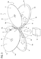
Figure 3 shows a functional detail of the forming unit of a part ofFigure 1 ; -
Figure 4 shows a front view of the detail ofFigure 4 . -
Figure 5 shows a perspective view, with some parts removed in order to better illustrate others, of a second embodiment of a disassembly device for smokers' articles according to this invention. - With reference to the accompanying drawings, the
numeral 1 denotes in its entirety a device for the disassembly of smokers' articles according to this invention. - Hereinafter, reference is made, by way of example only and hence without losing in generality, to smokers' articles such as cigarettes, in particular filter-tipped cigarettes.
- Each cigarette (or smokers' article "S") extends along its main axis "A" of extension and comprises at least a main portion "S1" and a filter "F" positioned in series along the axis "A".
- The main portion "S1" is basically a paper wrapper containing a predetermined quantity of tobacco.
- The filter "F", on the other hand, comprises a wrapper containing a piece of filter material.
- In some embodiments, which this text specifically refers to, the filter houses a discrete element "B", preferably containing a flavouring fluid for the cigarette.
- In the embodiment illustrated, the discrete element "B" is a capsule, preferably made of plastic material and containing a flavouring such as, for example, menthol or the like.
- In the rest of this text, the expression smokers' articles S" refers, unless otherwise specified, to the whole cigarettes, to the main portions "S1" or to the filters "F".
- The
disassembly device 1 is preferably associated with a machine 100 for making smokers' articles, in particular a filter tip attachment machine, that is to say, a machine configured to combine (in essentially known manner) a filter "F" with the corresponding main portion "S1" of each cigarette. More specifically, thedisassembly device 1 is operatively connected to a line which recovers/rejects the material and which, following a quality inspection, diverts defective cigarettes from the forming and packing path. Thedisassembly device 1 comprises feeding means 2 configured to move the smokers' articles "S" along a feed path "P"; - Thus, the feeding means 2 are associated with the machine 100 and, in particular, with the rejection/recovery line.
- Preferably, the feeding means 2 are configured to move the smokers' articles "S" in such a way that the feed path "P" is parallel to the axis "A". Thus, the feed path "P" is preferably, a longitudinal feed path.
- In the preferred embodiment, the feeding means 2 comprise at least one
conveyor 3 extending along a feed path "P" between its first end and itssecond end 3a. - The smokers' articles "S" are thus positioned in succession along the feed path "P".
- More precisely, the
conveyor 3 comprises at least one pair of opposed, facingbelts 4 respectively defining a first and a second means for feeding the smokers' articles "S". - In other words, the
belts 4 are facing and spaced from each other by an amount such as to allow each smokers' article "S" to pass in between while remaining in contact with both of them in order to be moved forward. Thus, the twobelts 4 define between them a channel whose transverse cross section is substantially equal to that of the smokers' article "S". - It should be noted that the space between the two
belts 4 at least partly defines a gap providing lateral access to the feed path "P", that is, to the smokers' articles "S". - In the embodiment illustrated, the two
belts 4 are located at the sides of the feed path "P", that is, at the sides of the smokers' articles "S", thus defining an upper access gap and a lower access gap. - Operatively downstream of (or at) the feeding means 2, the
disassembly device 1 further comprises cutting means 5 which operate along the feed path "P".,
The cutting means 5 are configured to make at least oneincision 50 on each smokers' article "S". - It should be noted that the
incision 50 defines a separating line between a first half-part 51 and a second half-part 52 of the smokers' article "S". Thus, the cutting means 5 are configured to make a cut in the smokers' article "S" which does not pass right through the latter and which facilitates subsequent separation of the two half-parts - Preferably, the cutting means 5 comprise at least one
blade 6 oriented in parallel with the central axis "A" of the smokers' article "S". - Thus, in the preferred embodiment, the
blade 6 is oriented in parallel with the feed path "P". That means theincision 50 is longitudinal. - More preferably, the cutting means 5 comprise a pair of
opposed blades 6 which make twoparallel incisions 50 delimiting the first half-part 51 and the second half-part 52 of the smokers' article "S". - More precisely, the
blades 6 are opposed and spaced in such a way that the feed path "P" is interposed between them in order to make twolongitudinal incisions 50 facing each other. - In the preferred embodiment, the two
blades 6 are substantially co-planar and located on opposite sides of the feed path "P". - Preferably, the
blades 6 are located at the lateral access gaps defined by the feeding means 2 and, more preferably, at the upper and lower access gap. - With reference to the accompanying drawings, the
cutting blades 6 are defined byrotatable cutting discs 6a, where the circumferential peripheral portion of each disc defines the cutting edge of the blade. - More in detail, the two
cutting discs 6a are mounted on the same forkedframe 7 with which both discs are rotatably associated. - An actuator (not illustrated) and transmission means 8, interposed between the actuator and the
discs 6a, are preferably also provided
With reference to the embodiment illustrated inFigures 1-4 , where the smokers' articles "S" are preferably filters "F" and contain at least one discrete element "B", the cutting means 5 are configured to make the separating line at the discrete element "B". - In other words, the cutting means 5, that is to say, the
blades 6, are positioned along a line running through the centre of the feed path "P". That way, the discrete element "B", or flavoured capsule, is positioned astride of the two half-parts - In other words, after cutting, the discrete element "B" is positioned partly in the first half-
part 51 and partly in the second half-part 52. - In the preferred embodiment, the cutting means 5 are configured to make two (or more)
incisions 50 in the smokers' article "S", in particular in the filter "T", each extending transversely to the axis, from the peripheral surface of the smokers' article "S" to an internal zone proximal to the discrete element "B". - Thus, the
incisions 50 are cut in such a way that eachincision 50 reaches to the depth of the discrete element, preferably without interfering with it. - Advantageously, the discrete element "B", or capsule, is thus not involved in cutting operations and does not come into contact with mechanical parts, making disassembly, and as will become clearer as this description continues, recovery, more precise and reliable.
- In order to allow removal of the discrete element "B" or recovery of the tobacco from the main portion "S1", the
disassembly device 1 comprises separating means 9 operatively located downstream of the cutting means 5 along the feed path "P" and configured to separate the first half-part 51 from the second half-part 52 of the smokers' article "S". - With reference to the embodiment of
Figures 1-4 , the separating means 9 comprise at least a firstgripping means 10a and a secondgripping means 10b, placed opposite each other. - Each gripping
means part 51 or the second half-part 52 of the smokers' article "S", respectively and to move them away from each other. - It should be noted that the gripping means apply a mechanical action on the first and second half-
parts - Advantageously, therefore, the two half-
parts - It should be noted that the first and second
gripping means - In effect, the gripping
means parts incision 50 or to theincisions 50. - In other words, to facilitate detachment of the discrete element "B", the separating means 9 and the first and second half-
parts blades 6 lie in. - Preferably, each gripping means 10a, 10b comprises a
first disc 11 and asecond disc 12, facing each other and rotatable about respective axes of rotation "R1 ", "R2". - The axes of rotation "R1 ", "R2 are oriented in such a way that in a gripping zone "T", proximal to the feed path "P", the
edges discs part 51 or second half-part 52. - More precisely, the axes of rotation "R1 ", "R2" of the
first disc 11 and of thesecond disc 12 are inclined to each other in such a way that, at least inside the gripping zone "T", the distance "d1" between therespective edges respective edges - Preferably, the axes of rotation "R1 ", "R2" of the
first disc 11 and of thesecond disc 12 of each gripping means are inclined to, and coplanar with, each other. - In the preferred embodiment, the inclination is between 20° and 70°, preferably approximately 50°.
- In order to improve the feeding action, each
first disc 11 has a chamferedperipheral edge 11 a, where the chamfer faces theperipheral edge 12a of the correspondingsecond disc 12, which is also chamfered. - It should be noted that in alternative embodiments, not illustrated, the gripping means might be embodied by grippers or other clamping parts. Again with reference to
figures 1-4 , the separating means 9 comprises ablowing unit 13 located at thegripping means part 51 and/or from the second half-part 52. - More specifically, the blowing
unit 13 is located immediately downstream of the gripping zone "T" along the feed path "P". - In the embodiment illustrated, the blowing
unit 13 comprises at least oneblowing nozzle 13a located above the feed path "P" and directed towards the feed path "P", transversely thereto. - Advantageously, that way, the blowing
nozzle 13a can produce an air flow which is substantially vertical (that is, predominantly vertical) directed from the top down in order to make it easier for the discrete element "B" to fall out. - In this regard, reclaiming means 14, located at the separating means 9, are preferably provided for receiving at least one discrete element "B" from inside the smokers' article "S".
- More specifically, the reclaiming means 14 comprise a channel or collector located on the side of the feed path "P" opposite to the
blowing unit 13. - In other words, in the embodiment illustrated, the blowing
nozzle 13a and the channel or collector 14a are located on opposite sides with reference to the feed path "P" of the smokers' articles "S". - Advantageously, that way, it is easy to collect and recover the discrete elements "B", or capsules, which can then be disposed of separately or re-used.
- With reference to
Figure 5 , the separating means 9 comprise a pair ofsuction units 15 configured to retain and release the first half-part 51 and the second half-part 52, respectively. - It should be noted that in this embodiment, the first and second half-
parts - Preferably, the pair of
suction units 15 comprises twodrums - The
drums circumferential suction channel - In other words, each
drum peripheral channel - Preferably, the circumferential channels meet at a gripping zone "T" in such a way as to define a gap whose cross section is substantially the same as that of the smokers' article "S".
- Advantageously, the two half-
parts suction units 15 while the tobacco contained in between may be recovered. - For this purpose, the embodiment discussed here also comprises collecting means 18, preferably operating by suction, for collecting the tobacco which is released when the two half-
parts - The collecting means 18 are preferably connected to a recovery channel (not illustrated) configured to transport the tobacco recovered to a feed station (also not illustrated) where the tobacco, not re-processed in any way and therefore suitable for making another cigarette is fed back into the machine.
- As stated above, this invention also has for an object a method for the disassembly of a smokers' article "S", preferably, but not exclusively, implemented by a disassembly device according to the invention.
- More specifically, in the two preferred embodiments, the method according to this invention may be implemented by the disassembly device illustrated in
Figures 1 to 4 or inFigure 5 . - The method comprises an initial step of feeding a plurality of smokers' articles "S", each extending along its central axis "A", in succession along a feed path "P".
- It should be noted that the feeding step is preferably carried out following a selecting and inspecting step where the defective smokers' articles "S" are detected and directed to the disassembly device.
- Preferably, the feeding step is performed in a direction parallel to the central axis of the smokers' articles "S".
- Thus, as described in connection with the device, the feed path "P" is parallel with the central axis "A" of the smokers' articles "S".
- After the feeding step, or concurrently therewith, the method comprises cutting each smokers' article "S" peripherally, that is, along a periphery thereof, in such a way as to make an
incision 50 defining the aforementioned separating line between the first half-part 51 and the second half-part 52 of the smokers' article "S". - More precisely, the cutting step comprises making at least one
longitudinal incision 50 substantially parallel to the central axis "A" of the smokers' article "S".. - In the preferred embodiment, the cutting step comprises making two (or more)
incisions 50 in the smokers' article "S", each extending transversely to the central axis "A", from the peripheral surface of the smokers' article "S" to an internal zone proximal to the discrete element "B". - If the method is implemented to dispose of and/or recover parts of composite filters "F" containing a discrete element "B" (for example, a flavoured capsule), the
incision 50 is made (or theincisions 50 are made) at the discrete element "B" itself. - Preferably, the incision or
incisions 50 is/are made along the centre line of the smokers' article "S". - More specifically, the
incisions 50 are cut in such a way that eachincision 50 reaches to the depth of the discrete element, preferably without interfering with it. - Advantageously, the discrete element "B", or capsule, is thus not involved in cutting operations and does not come into contact with mechanical parts, making disassembly, and as will become clearer as this description continues, recovery, more precise and reliable.
- In the method of the invention, the cutting step is followed by a step of separating the first half-
part 51 from the second half-part 52. - In a first embodiment, this step is carried out to allow releasing the discrete element "B".
- In a first embodiment, the separating step comprises a substep, performed in a specific gripping zone "T", of picking up or gripping each half-
part - After being gripped, the half-
parts - Preferably, there is also a step of pneumatically pushing the discrete element away from the half-parts, performed by a blowing unit or the like. Preferably, the step of releasing the discrete element "B" is carried out by allowing the discrete element "B" to fall out.
- This embodiment comprises a step of recovering the discrete element "B" concurrently with, or immediately after, the separating step.
- In an alternative embodiment, preferably applicable to the main portions "S1" of the defective cigarettes "S", the separating step comprises sucking the first half-
part 51 and the second half-part 52 in opposite directions. This sucking action is preferably applied by means of suction cavities or drums similar to those described above. - It should be noted that this embodiment comprises a suction step, concurrent with the separating step, to extract the tobacco from the smokers' article.
- Further, the reclaimed tobacco is preferably returned through specific ducts into the process of forming new smokers' articles/cigarettes.
- The invention achieves the above mentioned aims and brings important advantages.
- In effect, a disassembly device in which the cutting blades divide each article into two half-parts, preferably longitudinal, which are then moved apart, allows the tobacco or the discrete elements to be recovered without being damaged by the blades or other mechanical parts.
- Moreover, separating the two half-parts using the gripping means, which are preferably disc-shaped, makes it easier to complete the separating action initiated by the blades and thus facilitates releasing the discrete elements.
Claims (21)
- A device for the disassembly of smokers' articles, where the smokers' articles extend along a central axis (A), the device comprising:feeding means (2) configured to move the smokers' articles (S) along a feed path (P);cutting means (5) operating along the feed path (P) and configured to make at least one incision (50) on each smokers' article (S), where the incision defines a separating line between a first half-part (51) and a second half-part (52) of the smokers' article (S);separating means (9) operatively located downstream of the cutting means (5) along the feed path (P) and configured to separate the first half-part (51) from the second half-part (52) of the smokers' article (S).
- The disassembly device according to claim 1, characterized in that the separating means (9) comprise at least a first gripping means (10a) and a second gripping means (10b) located opposite each other and each being configured to receive the first half-part (51) or the second half-part (52) of the smokers' article (S), respectively, and to move them away from each other.
- The disassembly device according to claim 2, characterized in that the first gripping means (10a) and the second gripping means (10b) are oriented transversely to the cutting means (5).
- The disassembly device according to claim 2 or 3, characterized in that each gripping means (10a, 10b) comprises a first disc (11) and a second disc (12) facing each other and rotatable about respective axes of rotation (R1, R2) inclined to each other in such a way that in a gripping zone (T), proximal to the feed path (P), the edges (11 a, 12a) of the discs (11, 12) are close to each other so as to apply a gripping action on one side of the respective first half-part (51) or second half-part (52).
- The disassembly device according to any one of claims 1 to 3, characterized in that the separating means (9) comprise a pair of suction units (15) configured to retain and release the first half-part (51) and the second half-part (52), respectively.
- The disassembly device according to claim 5, characterized in that the pair of suction units (15) comprises two drums (16, 17) which are, rotatable about parallel axes transversal to the feed path (P) and which are mounted in such a way that their respective peripheries are substantially tangent at the feed path (P); both of the peripheries being provided with a circumferential suction channel (16a, 17a).
- The disassembly device according to any one of the preceding claims, characterized in that the cutting means (5) comprise at least one blade (6) oriented in parallel with the central axis (A) so that the incision (50) is longitudinal.
- The disassembly device according to any one of the preceding claims, characterized in that the smokers' articles comprise at least one discrete element (B) inside them; the cutting means (5) being configured to make the separating line at the discrete element (B) so that the discrete element (B) is positioned partly in the first half-part (51) and partly in the second half-part (52).
- The disassembly device according to claim 8, characterized in that the cutting means (5) comprise at least one pair of blades (6) mounted opposite to and spaced from each other in such a way that the feed path (P) is interposed between the two blades (6) so as to make two longitudinal incisions (50) which face each other and between which the at least one discrete element (B) is interposed.
- The disassembly device according to any one of the preceding claims, characterized in that the feed path (P) is parallel with the central axis (A).
- The disassembly device according to any one of the preceding claims, characterized in that it comprises reclaiming means (14) located at the separating means (9) and designed to receive at least one discrete element (B) from inside the smokers' article (S).
- The disassembly device according to any one of the preceding claims, characterized in that the separating means (9) comprise a blowing unit (13) located immediately downstream of the gripping zone (T) along the feed path (P) and configured to produce an air flow transversal to the feed path (P) to facilitate separation of the discrete element (B) from the first half-part (51) or second half-part (52).
- A method for the disassembly of a smokers' article, comprising the steps of:feeding a plurality of smokers' articles (S), each extending along its central axis (A), in succession along a feed path (P);peripherally cutting each smokers' article (S) in such a way as to make an incision (50) defining a separating line between a first half-part (51) and a second half-part (52) of the smokers' article (S);separating the first half-part (51) from the second half-part (52);reclaiming at least one element contained in the first half-part (51) and in the second half-part (52).
- The method according to claim 13, characterized in that the feeding step comprises moving a succession of smokers' articles (S) in parallel with the central axis (A).
- The method according to claim 13 or 14, characterized in that the cutting step comprises making at least one longitudinal incision (50) substantially parallel to the central axis (A) of the smokers' article (S).
- The method according to any one of claims 13 to 15, characterized in that the smokers' articles (S) comprise at least one discrete element (B) inside them; the reclaiming step comprising a step of reclaiming the discrete element (B) concurrently with or immediately after the separating step.
- The method according to claim 16, characterized in that the reclaiming step is accomplished by allowing the discrete element (B) to drop.
- The method according to claim 16 or 17, characterized in that the cutting step is performed along a centre line of the smokers' article (S), at the discrete element (B).
- The method according to any one of claims 16 to 18, characterized in that the separating step comprises the following sub-steps:gripping or holding each half-part (51, 52);moving the first half-part (51) and the second half-part (52) away from each other.
- The method according to any one of claims 13 to 15, characterized in that the separating step comprises sucking the first half-part (51) and the second half-part (52) in opposite directions.
- The method according to claim 20, characterized in that the reclaiming step comprises a suction step, concurrent with the separating step, to extract the tobacco from the smokers' article.
Priority Applications (1)
| Application Number | Priority Date | Filing Date | Title |
|---|---|---|---|
| PL16177629T PL3114945T3 (en) | 2015-07-06 | 2016-07-01 | Disassembly device and disassembly method for smokers' articles |
Applications Claiming Priority (1)
| Application Number | Priority Date | Filing Date | Title |
|---|---|---|---|
| ITUB2015A001947A ITUB20151947A1 (en) | 2015-07-06 | 2015-07-06 | Unpacking device and method of break-up for smoking items |
Publications (2)
| Publication Number | Publication Date |
|---|---|
| EP3114945A1 true EP3114945A1 (en) | 2017-01-11 |
| EP3114945B1 EP3114945B1 (en) | 2018-05-09 |
Family
ID=54288943
Family Applications (1)
| Application Number | Title | Priority Date | Filing Date |
|---|---|---|---|
| EP16177629.9A Active EP3114945B1 (en) | 2015-07-06 | 2016-07-01 | Disassembly device and disassembly method for smokers' articles |
Country Status (4)
| Country | Link |
|---|---|
| EP (1) | EP3114945B1 (en) |
| IT (1) | ITUB20151947A1 (en) |
| PL (1) | PL3114945T3 (en) |
| TR (1) | TR201809049T4 (en) |
Cited By (4)
| Publication number | Priority date | Publication date | Assignee | Title |
|---|---|---|---|---|
| CN106858713A (en) * | 2017-04-20 | 2017-06-20 | 河南中烟工业有限责任公司 | A kind of plume separator |
| WO2022079668A1 (en) * | 2020-10-15 | 2022-04-21 | Philip Morris Products S.A. | Susceptor heating element extraction |
| CN118415382A (en) * | 2024-05-27 | 2024-08-02 | 红塔烟草(集团)有限责任公司 | A method for recycling waste cigarettes containing filter particle additives |
| RU2844547C1 (en) * | 2020-10-15 | 2025-08-04 | Филип Моррис Продактс С.А. | Unit for facilitating removal of current-collecting heating element from aerosol-generating article, cutting tool for facilitating removal of current-collected heating element from aerosol-generating article, use of cutting tool and method for removing current-collected heating element from aerosol-generating article |
Families Citing this family (1)
| Publication number | Priority date | Publication date | Assignee | Title |
|---|---|---|---|---|
| CN110973691B (en) * | 2019-12-03 | 2020-12-25 | 红塔烟草(集团)有限责任公司 | Filter rod explodes pearl recovery plant |
Citations (7)
| Publication number | Priority date | Publication date | Assignee | Title |
|---|---|---|---|---|
| DE1893470U (en) * | 1961-12-15 | 1964-05-21 | Hauni Werke Koerber & Co Kg | DEVICE FOR SEPARATING CIGARETTES AND FILTERS, OR OTHER DIFFERENT ROD-SHAPED OBJECTS, INTO THEIR COMPONENTS. |
| EP2545790A1 (en) * | 2011-07-12 | 2013-01-16 | Köhl Maschinenbau AG | Cigarette disassembly device for filter cigarettes and cigarette disassembly machine and method for disassembling a filter cigarette |
| WO2013030286A1 (en) * | 2011-09-01 | 2013-03-07 | Garbuio S.P.A. | Tobacco reclaim from waste cigarettes |
| WO2013064352A1 (en) * | 2011-10-31 | 2013-05-10 | British American Tobacco (Investments) Limited | Smokeable material recovery |
| EP2730182A2 (en) | 2012-11-08 | 2014-05-14 | Köhl Maschinenbau AG | Device and method for recovering of smoking article parts from smoking articles |
| EP2730184A2 (en) | 2012-11-08 | 2014-05-14 | Köhl Maschinenbau AG | Device and method for recovering bodies from smoking articles |
| EP2730183A2 (en) * | 2012-11-08 | 2014-05-14 | Köhl Maschinenbau AG | Device and method for reclaiming tobacco from smoking articles |
-
2015
- 2015-07-06 IT ITUB2015A001947A patent/ITUB20151947A1/en unknown
-
2016
- 2016-07-01 TR TR2018/09049T patent/TR201809049T4/en unknown
- 2016-07-01 PL PL16177629T patent/PL3114945T3/en unknown
- 2016-07-01 EP EP16177629.9A patent/EP3114945B1/en active Active
Patent Citations (7)
| Publication number | Priority date | Publication date | Assignee | Title |
|---|---|---|---|---|
| DE1893470U (en) * | 1961-12-15 | 1964-05-21 | Hauni Werke Koerber & Co Kg | DEVICE FOR SEPARATING CIGARETTES AND FILTERS, OR OTHER DIFFERENT ROD-SHAPED OBJECTS, INTO THEIR COMPONENTS. |
| EP2545790A1 (en) * | 2011-07-12 | 2013-01-16 | Köhl Maschinenbau AG | Cigarette disassembly device for filter cigarettes and cigarette disassembly machine and method for disassembling a filter cigarette |
| WO2013030286A1 (en) * | 2011-09-01 | 2013-03-07 | Garbuio S.P.A. | Tobacco reclaim from waste cigarettes |
| WO2013064352A1 (en) * | 2011-10-31 | 2013-05-10 | British American Tobacco (Investments) Limited | Smokeable material recovery |
| EP2730182A2 (en) | 2012-11-08 | 2014-05-14 | Köhl Maschinenbau AG | Device and method for recovering of smoking article parts from smoking articles |
| EP2730184A2 (en) | 2012-11-08 | 2014-05-14 | Köhl Maschinenbau AG | Device and method for recovering bodies from smoking articles |
| EP2730183A2 (en) * | 2012-11-08 | 2014-05-14 | Köhl Maschinenbau AG | Device and method for reclaiming tobacco from smoking articles |
Cited By (7)
| Publication number | Priority date | Publication date | Assignee | Title |
|---|---|---|---|---|
| CN106858713A (en) * | 2017-04-20 | 2017-06-20 | 河南中烟工业有限责任公司 | A kind of plume separator |
| CN106858713B (en) * | 2017-04-20 | 2019-04-26 | 河南中烟工业有限责任公司 | A device for separating tobacco rods |
| WO2022079668A1 (en) * | 2020-10-15 | 2022-04-21 | Philip Morris Products S.A. | Susceptor heating element extraction |
| CN116194002A (en) * | 2020-10-15 | 2023-05-30 | 菲利普莫里斯生产公司 | Removal of susceptor heating element |
| US20230380478A1 (en) * | 2020-10-15 | 2023-11-30 | Philip Morris Prodcuts S.A. | Susceptor heating element extraction |
| RU2844547C1 (en) * | 2020-10-15 | 2025-08-04 | Филип Моррис Продактс С.А. | Unit for facilitating removal of current-collecting heating element from aerosol-generating article, cutting tool for facilitating removal of current-collected heating element from aerosol-generating article, use of cutting tool and method for removing current-collected heating element from aerosol-generating article |
| CN118415382A (en) * | 2024-05-27 | 2024-08-02 | 红塔烟草(集团)有限责任公司 | A method for recycling waste cigarettes containing filter particle additives |
Also Published As
| Publication number | Publication date |
|---|---|
| EP3114945B1 (en) | 2018-05-09 |
| TR201809049T4 (en) | 2018-07-23 |
| PL3114945T3 (en) | 2018-09-28 |
| ITUB20151947A1 (en) | 2017-01-06 |
Similar Documents
| Publication | Publication Date | Title |
|---|---|---|
| EP3114945B1 (en) | Disassembly device and disassembly method for smokers' articles | |
| EP2978325B1 (en) | Method and a machine for making cigarettes, with recovery of tobacco from defective cigarettes | |
| EP2773228B1 (en) | Smokeable material recovery | |
| EP1833723B1 (en) | Parallel cigarette filter combining techniques with particle filling of cavities | |
| GB2494159A (en) | Cigarette processing assembly for reclaiming tobacco | |
| US3224451A (en) | Apparatus for removal of tips from scrap cigarettes | |
| EP2750525B1 (en) | Tobacco reclaim from waste cigarettes | |
| JP5751653B2 (en) | Filter mounting device | |
| JP2013523119A (en) | Method and apparatus for compensating for instantaneous absence of filter segments in a multi-segment filter production line | |
| EP3197302B1 (en) | Machine for making smokers' articles | |
| US20080202070A1 (en) | Culling method for blister-pack production line | |
| US20150068376A1 (en) | Cleaning system for drum conveyor of apparatus for feeding filter segments to multi-segment filter manufacturing apparatus and method of cleaning of drum conveyor | |
| CN102188045A (en) | Method of opening cigarette covers and an assembly for opening cigarette covers in a machine for recovering tobacco from defective and/or substandard cigarettes | |
| US5001951A (en) | Apparatus for cutting apart cigarette packs in preparation for recovery of the tobacco in the cigarettes | |
| US5117843A (en) | Method of and apparatus for reclaiming tobacco from cigarette packages | |
| US3233613A (en) | Method and apparatus for reclaiming defective cigarette assemblies and the like | |
| WO2013075791A1 (en) | Apparatus and method for deconstructing a smoking article | |
| US5086790A (en) | Method of and apparatus for reclaiming cigarettes from cigarette packages | |
| KR100331389B1 (en) | Apparatus and method used for unpacking of packaged goods | |
| CN214826418U (en) | Hollow filter stick transferring and conveying assembly | |
| US6971213B2 (en) | Method for the separate rejection of defective items, in particular strip packages, during transferring from a packaging line to a conveying line | |
| JPS59174432A (en) | Method and device used for disassembling packing of packed article | |
| JPH04339716A (en) | Cigarette rejecting device for cigarette packaging device | |
| CN1317987C (en) | Device and a method for separating at least one continuous rod of forming material for tobacco products | |
| EP4570083B1 (en) | A device for separating a multi-segment rod-like article of tobacco industry |
Legal Events
| Date | Code | Title | Description |
|---|---|---|---|
| PUAI | Public reference made under article 153(3) epc to a published international application that has entered the european phase |
Free format text: ORIGINAL CODE: 0009012 |
|
| AK | Designated contracting states |
Kind code of ref document: A1 Designated state(s): AL AT BE BG CH CY CZ DE DK EE ES FI FR GB GR HR HU IE IS IT LI LT LU LV MC MK MT NL NO PL PT RO RS SE SI SK SM TR |
|
| AX | Request for extension of the european patent |
Extension state: BA ME |
|
| 17P | Request for examination filed |
Effective date: 20170711 |
|
| RBV | Designated contracting states (corrected) |
Designated state(s): AL AT BE BG CH CY CZ DE DK EE ES FI FR GB GR HR HU IE IS IT LI LT LU LV MC MK MT NL NO PL PT RO RS SE SI SK SM TR |
|
| GRAJ | Information related to disapproval of communication of intention to grant by the applicant or resumption of examination proceedings by the epo deleted |
Free format text: ORIGINAL CODE: EPIDOSDIGR1 |
|
| GRAP | Despatch of communication of intention to grant a patent |
Free format text: ORIGINAL CODE: EPIDOSNIGR1 |
|
| RIC1 | Information provided on ipc code assigned before grant |
Ipc: A24C 5/36 20060101AFI20171120BHEP |
|
| INTG | Intention to grant announced |
Effective date: 20171212 |
|
| GRAS | Grant fee paid |
Free format text: ORIGINAL CODE: EPIDOSNIGR3 |
|
| GRAA | (expected) grant |
Free format text: ORIGINAL CODE: 0009210 |
|
| AK | Designated contracting states |
Kind code of ref document: B1 Designated state(s): AL AT BE BG CH CY CZ DE DK EE ES FI FR GB GR HR HU IE IS IT LI LT LU LV MC MK MT NL NO PL PT RO RS SE SI SK SM TR |
|
| REG | Reference to a national code |
Ref country code: GB Ref legal event code: FG4D |
|
| REG | Reference to a national code |
Ref country code: CH Ref legal event code: EP Ref country code: AT Ref legal event code: REF Ref document number: 996687 Country of ref document: AT Kind code of ref document: T Effective date: 20180515 |
|
| REG | Reference to a national code |
Ref country code: IE Ref legal event code: FG4D |
|
| REG | Reference to a national code |
Ref country code: DE Ref legal event code: R096 Ref document number: 602016002910 Country of ref document: DE |
|
| REG | Reference to a national code |
Ref country code: RO Ref legal event code: EPE |
|
| PGFP | Annual fee paid to national office [announced via postgrant information from national office to epo] |
Ref country code: RO Payment date: 20180627 Year of fee payment: 3 |
|
| REG | Reference to a national code |
Ref country code: NL Ref legal event code: MP Effective date: 20180509 |
|
| REG | Reference to a national code |
Ref country code: LT Ref legal event code: MG4D |
|
| PG25 | Lapsed in a contracting state [announced via postgrant information from national office to epo] |
Ref country code: LT Free format text: LAPSE BECAUSE OF FAILURE TO SUBMIT A TRANSLATION OF THE DESCRIPTION OR TO PAY THE FEE WITHIN THE PRESCRIBED TIME-LIMIT Effective date: 20180509 Ref country code: FI Free format text: LAPSE BECAUSE OF FAILURE TO SUBMIT A TRANSLATION OF THE DESCRIPTION OR TO PAY THE FEE WITHIN THE PRESCRIBED TIME-LIMIT Effective date: 20180509 Ref country code: BG Free format text: LAPSE BECAUSE OF FAILURE TO SUBMIT A TRANSLATION OF THE DESCRIPTION OR TO PAY THE FEE WITHIN THE PRESCRIBED TIME-LIMIT Effective date: 20180809 Ref country code: ES Free format text: LAPSE BECAUSE OF FAILURE TO SUBMIT A TRANSLATION OF THE DESCRIPTION OR TO PAY THE FEE WITHIN THE PRESCRIBED TIME-LIMIT Effective date: 20180509 Ref country code: SE Free format text: LAPSE BECAUSE OF FAILURE TO SUBMIT A TRANSLATION OF THE DESCRIPTION OR TO PAY THE FEE WITHIN THE PRESCRIBED TIME-LIMIT Effective date: 20180509 Ref country code: NO Free format text: LAPSE BECAUSE OF FAILURE TO SUBMIT A TRANSLATION OF THE DESCRIPTION OR TO PAY THE FEE WITHIN THE PRESCRIBED TIME-LIMIT Effective date: 20180809 |
|
| PG25 | Lapsed in a contracting state [announced via postgrant information from national office to epo] |
Ref country code: GR Free format text: LAPSE BECAUSE OF FAILURE TO SUBMIT A TRANSLATION OF THE DESCRIPTION OR TO PAY THE FEE WITHIN THE PRESCRIBED TIME-LIMIT Effective date: 20180810 Ref country code: LV Free format text: LAPSE BECAUSE OF FAILURE TO SUBMIT A TRANSLATION OF THE DESCRIPTION OR TO PAY THE FEE WITHIN THE PRESCRIBED TIME-LIMIT Effective date: 20180509 Ref country code: HR Free format text: LAPSE BECAUSE OF FAILURE TO SUBMIT A TRANSLATION OF THE DESCRIPTION OR TO PAY THE FEE WITHIN THE PRESCRIBED TIME-LIMIT Effective date: 20180509 Ref country code: RS Free format text: LAPSE BECAUSE OF FAILURE TO SUBMIT A TRANSLATION OF THE DESCRIPTION OR TO PAY THE FEE WITHIN THE PRESCRIBED TIME-LIMIT Effective date: 20180509 Ref country code: NL Free format text: LAPSE BECAUSE OF FAILURE TO SUBMIT A TRANSLATION OF THE DESCRIPTION OR TO PAY THE FEE WITHIN THE PRESCRIBED TIME-LIMIT Effective date: 20180509 |
|
| REG | Reference to a national code |
Ref country code: AT Ref legal event code: MK05 Ref document number: 996687 Country of ref document: AT Kind code of ref document: T Effective date: 20180509 |
|
| PG25 | Lapsed in a contracting state [announced via postgrant information from national office to epo] |
Ref country code: AT Free format text: LAPSE BECAUSE OF FAILURE TO SUBMIT A TRANSLATION OF THE DESCRIPTION OR TO PAY THE FEE WITHIN THE PRESCRIBED TIME-LIMIT Effective date: 20180509 Ref country code: SK Free format text: LAPSE BECAUSE OF FAILURE TO SUBMIT A TRANSLATION OF THE DESCRIPTION OR TO PAY THE FEE WITHIN THE PRESCRIBED TIME-LIMIT Effective date: 20180509 Ref country code: CZ Free format text: LAPSE BECAUSE OF FAILURE TO SUBMIT A TRANSLATION OF THE DESCRIPTION OR TO PAY THE FEE WITHIN THE PRESCRIBED TIME-LIMIT Effective date: 20180509 Ref country code: EE Free format text: LAPSE BECAUSE OF FAILURE TO SUBMIT A TRANSLATION OF THE DESCRIPTION OR TO PAY THE FEE WITHIN THE PRESCRIBED TIME-LIMIT Effective date: 20180509 Ref country code: DK Free format text: LAPSE BECAUSE OF FAILURE TO SUBMIT A TRANSLATION OF THE DESCRIPTION OR TO PAY THE FEE WITHIN THE PRESCRIBED TIME-LIMIT Effective date: 20180509 |
|
| REG | Reference to a national code |
Ref country code: DE Ref legal event code: R097 Ref document number: 602016002910 Country of ref document: DE |
|
| PG25 | Lapsed in a contracting state [announced via postgrant information from national office to epo] |
Ref country code: SM Free format text: LAPSE BECAUSE OF FAILURE TO SUBMIT A TRANSLATION OF THE DESCRIPTION OR TO PAY THE FEE WITHIN THE PRESCRIBED TIME-LIMIT Effective date: 20180509 Ref country code: IT Free format text: LAPSE BECAUSE OF FAILURE TO SUBMIT A TRANSLATION OF THE DESCRIPTION OR TO PAY THE FEE WITHIN THE PRESCRIBED TIME-LIMIT Effective date: 20180509 |
|
| PLBE | No opposition filed within time limit |
Free format text: ORIGINAL CODE: 0009261 |
|
| STAA | Information on the status of an ep patent application or granted ep patent |
Free format text: STATUS: NO OPPOSITION FILED WITHIN TIME LIMIT |
|
| PG25 | Lapsed in a contracting state [announced via postgrant information from national office to epo] |
Ref country code: LU Free format text: LAPSE BECAUSE OF NON-PAYMENT OF DUE FEES Effective date: 20180701 Ref country code: MC Free format text: LAPSE BECAUSE OF FAILURE TO SUBMIT A TRANSLATION OF THE DESCRIPTION OR TO PAY THE FEE WITHIN THE PRESCRIBED TIME-LIMIT Effective date: 20180509 |
|
| REG | Reference to a national code |
Ref country code: BE Ref legal event code: MM Effective date: 20180731 |
|
| 26N | No opposition filed |
Effective date: 20190212 |
|
| REG | Reference to a national code |
Ref country code: IE Ref legal event code: MM4A |
|
| PG25 | Lapsed in a contracting state [announced via postgrant information from national office to epo] |
Ref country code: FR Free format text: LAPSE BECAUSE OF NON-PAYMENT OF DUE FEES Effective date: 20180709 Ref country code: IE Free format text: LAPSE BECAUSE OF NON-PAYMENT OF DUE FEES Effective date: 20180701 |
|
| PG25 | Lapsed in a contracting state [announced via postgrant information from national office to epo] |
Ref country code: SI Free format text: LAPSE BECAUSE OF FAILURE TO SUBMIT A TRANSLATION OF THE DESCRIPTION OR TO PAY THE FEE WITHIN THE PRESCRIBED TIME-LIMIT Effective date: 20180509 Ref country code: BE Free format text: LAPSE BECAUSE OF NON-PAYMENT OF DUE FEES Effective date: 20180731 |
|
| PG25 | Lapsed in a contracting state [announced via postgrant information from national office to epo] |
Ref country code: AL Free format text: LAPSE BECAUSE OF FAILURE TO SUBMIT A TRANSLATION OF THE DESCRIPTION OR TO PAY THE FEE WITHIN THE PRESCRIBED TIME-LIMIT Effective date: 20180509 |
|
| PG25 | Lapsed in a contracting state [announced via postgrant information from national office to epo] |
Ref country code: MT Free format text: LAPSE BECAUSE OF NON-PAYMENT OF DUE FEES Effective date: 20180701 |
|
| REG | Reference to a national code |
Ref country code: CH Ref legal event code: PL |
|
| PG25 | Lapsed in a contracting state [announced via postgrant information from national office to epo] |
Ref country code: RO Free format text: LAPSE BECAUSE OF NON-PAYMENT OF DUE FEES Effective date: 20190701 |
|
| PG25 | Lapsed in a contracting state [announced via postgrant information from national office to epo] |
Ref country code: LI Free format text: LAPSE BECAUSE OF NON-PAYMENT OF DUE FEES Effective date: 20190731 Ref country code: CH Free format text: LAPSE BECAUSE OF NON-PAYMENT OF DUE FEES Effective date: 20190731 Ref country code: PT Free format text: LAPSE BECAUSE OF FAILURE TO SUBMIT A TRANSLATION OF THE DESCRIPTION OR TO PAY THE FEE WITHIN THE PRESCRIBED TIME-LIMIT Effective date: 20180509 |
|
| PG25 | Lapsed in a contracting state [announced via postgrant information from national office to epo] |
Ref country code: HU Free format text: LAPSE BECAUSE OF FAILURE TO SUBMIT A TRANSLATION OF THE DESCRIPTION OR TO PAY THE FEE WITHIN THE PRESCRIBED TIME-LIMIT; INVALID AB INITIO Effective date: 20160701 Ref country code: MK Free format text: LAPSE BECAUSE OF NON-PAYMENT OF DUE FEES Effective date: 20180509 Ref country code: CY Free format text: LAPSE BECAUSE OF FAILURE TO SUBMIT A TRANSLATION OF THE DESCRIPTION OR TO PAY THE FEE WITHIN THE PRESCRIBED TIME-LIMIT Effective date: 20180509 |
|
| PG25 | Lapsed in a contracting state [announced via postgrant information from national office to epo] |
Ref country code: IS Free format text: LAPSE BECAUSE OF FAILURE TO SUBMIT A TRANSLATION OF THE DESCRIPTION OR TO PAY THE FEE WITHIN THE PRESCRIBED TIME-LIMIT Effective date: 20180909 |
|
| GBPC | Gb: european patent ceased through non-payment of renewal fee |
Effective date: 20200701 |
|
| PG25 | Lapsed in a contracting state [announced via postgrant information from national office to epo] |
Ref country code: GB Free format text: LAPSE BECAUSE OF NON-PAYMENT OF DUE FEES Effective date: 20200701 |
|
| PG25 | Lapsed in a contracting state [announced via postgrant information from national office to epo] |
Ref country code: TR Free format text: LAPSE BECAUSE OF NON-PAYMENT OF DUE FEES Effective date: 20190701 |
|
| P01 | Opt-out of the competence of the unified patent court (upc) registered |
Effective date: 20230526 |
|
| PGFP | Annual fee paid to national office [announced via postgrant information from national office to epo] |
Ref country code: DE Payment date: 20250729 Year of fee payment: 10 |
|
| PGFP | Annual fee paid to national office [announced via postgrant information from national office to epo] |
Ref country code: PL Payment date: 20260618 Year of fee payment: 11 |