EP3114824B1 - Dispositif de communication mobile avec surfaces modelées - Google Patents
Dispositif de communication mobile avec surfaces modelées Download PDFInfo
- Publication number
- EP3114824B1 EP3114824B1 EP15710047.0A EP15710047A EP3114824B1 EP 3114824 B1 EP3114824 B1 EP 3114824B1 EP 15710047 A EP15710047 A EP 15710047A EP 3114824 B1 EP3114824 B1 EP 3114824B1
- Authority
- EP
- European Patent Office
- Prior art keywords
- mobile communication
- communication device
- concavity
- concavities
- enhanced grip
- Prior art date
- Legal status (The legal status is an assumption and is not a legal conclusion. Google has not performed a legal analysis and makes no representation as to the accuracy of the status listed.)
- Active
Links
- 238000010295 mobile communication Methods 0.000 title claims description 31
- 238000004891 communication Methods 0.000 description 30
- 238000000034 method Methods 0.000 description 16
- 238000003860 storage Methods 0.000 description 14
- 230000006870 function Effects 0.000 description 13
- 230000033001 locomotion Effects 0.000 description 10
- 239000000758 substrate Substances 0.000 description 9
- 210000003811 finger Anatomy 0.000 description 8
- 239000000463 material Substances 0.000 description 8
- 230000015654 memory Effects 0.000 description 8
- 241001422033 Thestylus Species 0.000 description 7
- 238000005516 engineering process Methods 0.000 description 5
- 230000004913 activation Effects 0.000 description 4
- 230000002146 bilateral effect Effects 0.000 description 4
- 238000004590 computer program Methods 0.000 description 4
- 230000004044 response Effects 0.000 description 4
- 210000003813 thumb Anatomy 0.000 description 4
- 239000003086 colorant Substances 0.000 description 3
- 238000013461 design Methods 0.000 description 3
- 238000001514 detection method Methods 0.000 description 3
- 230000000694 effects Effects 0.000 description 3
- 238000004519 manufacturing process Methods 0.000 description 3
- 238000012545 processing Methods 0.000 description 3
- 238000005452 bending Methods 0.000 description 2
- 238000005219 brazing Methods 0.000 description 2
- 230000001413 cellular effect Effects 0.000 description 2
- 238000007906 compression Methods 0.000 description 2
- 230000006835 compression Effects 0.000 description 2
- 238000013480 data collection Methods 0.000 description 2
- 238000010586 diagram Methods 0.000 description 2
- 230000005484 gravity Effects 0.000 description 2
- 238000003384 imaging method Methods 0.000 description 2
- 238000001746 injection moulding Methods 0.000 description 2
- 239000004973 liquid crystal related substance Substances 0.000 description 2
- 238000003754 machining Methods 0.000 description 2
- 230000003287 optical effect Effects 0.000 description 2
- 230000000717 retained effect Effects 0.000 description 2
- 238000005476 soldering Methods 0.000 description 2
- 238000003466 welding Methods 0.000 description 2
- RTAQQCXQSZGOHL-UHFFFAOYSA-N Titanium Chemical compound [Ti] RTAQQCXQSZGOHL-UHFFFAOYSA-N 0.000 description 1
- 230000001133 acceleration Effects 0.000 description 1
- 230000003213 activating effect Effects 0.000 description 1
- 229910052782 aluminium Inorganic materials 0.000 description 1
- XAGFODPZIPBFFR-UHFFFAOYSA-N aluminium Chemical compound [Al] XAGFODPZIPBFFR-UHFFFAOYSA-N 0.000 description 1
- 210000003484 anatomy Anatomy 0.000 description 1
- 230000005540 biological transmission Effects 0.000 description 1
- 239000008280 blood Substances 0.000 description 1
- 210000004369 blood Anatomy 0.000 description 1
- 239000011449 brick Substances 0.000 description 1
- 238000010276 construction Methods 0.000 description 1
- 238000013479 data entry Methods 0.000 description 1
- 230000001419 dependent effect Effects 0.000 description 1
- 230000001066 destructive effect Effects 0.000 description 1
- 230000009977 dual effect Effects 0.000 description 1
- 238000009760 electrical discharge machining Methods 0.000 description 1
- 230000002708 enhancing effect Effects 0.000 description 1
- 230000005358 geomagnetic field Effects 0.000 description 1
- 238000000227 grinding Methods 0.000 description 1
- 230000036541 health Effects 0.000 description 1
- 238000005286 illumination Methods 0.000 description 1
- 238000007373 indentation Methods 0.000 description 1
- 238000010329 laser etching Methods 0.000 description 1
- 229910052751 metal Inorganic materials 0.000 description 1
- 239000002184 metal Substances 0.000 description 1
- 238000003801 milling Methods 0.000 description 1
- 238000000465 moulding Methods 0.000 description 1
- 210000003205 muscle Anatomy 0.000 description 1
- 230000001151 other effect Effects 0.000 description 1
- 230000002093 peripheral effect Effects 0.000 description 1
- 230000001681 protective effect Effects 0.000 description 1
- 238000009877 rendering Methods 0.000 description 1
- 239000007779 soft material Substances 0.000 description 1
- 239000007787 solid Substances 0.000 description 1
- 239000000243 solution Substances 0.000 description 1
- 229910001220 stainless steel Inorganic materials 0.000 description 1
- 239000010935 stainless steel Substances 0.000 description 1
- 230000001360 synchronised effect Effects 0.000 description 1
- 239000010409 thin film Substances 0.000 description 1
- 239000010936 titanium Substances 0.000 description 1
- 229910052719 titanium Inorganic materials 0.000 description 1
- 238000012546 transfer Methods 0.000 description 1
- 239000012780 transparent material Substances 0.000 description 1
- 239000011800 void material Substances 0.000 description 1
Images


Classifications
-
- H—ELECTRICITY
- H04—ELECTRIC COMMUNICATION TECHNIQUE
- H04M—TELEPHONIC COMMUNICATION
- H04M1/00—Substation equipment, e.g. for use by subscribers
- H04M1/02—Constructional features of telephone sets
- H04M1/0202—Portable telephone sets, e.g. cordless phones, mobile phones or bar type handsets
-
- G—PHYSICS
- G03—PHOTOGRAPHY; CINEMATOGRAPHY; ANALOGOUS TECHNIQUES USING WAVES OTHER THAN OPTICAL WAVES; ELECTROGRAPHY; HOLOGRAPHY
- G03B—APPARATUS OR ARRANGEMENTS FOR TAKING PHOTOGRAPHS OR FOR PROJECTING OR VIEWING THEM; APPARATUS OR ARRANGEMENTS EMPLOYING ANALOGOUS TECHNIQUES USING WAVES OTHER THAN OPTICAL WAVES; ACCESSORIES THEREFOR
- G03B15/00—Special procedures for taking photographs; Apparatus therefor
- G03B15/02—Illuminating scene
- G03B15/03—Combinations of cameras with lighting apparatus; Flash units
-
- G—PHYSICS
- G06—COMPUTING; CALCULATING OR COUNTING
- G06F—ELECTRIC DIGITAL DATA PROCESSING
- G06F1/00—Details not covered by groups G06F3/00 - G06F13/00 and G06F21/00
- G06F1/16—Constructional details or arrangements
- G06F1/1613—Constructional details or arrangements for portable computers
- G06F1/1626—Constructional details or arrangements for portable computers with a single-body enclosure integrating a flat display, e.g. Personal Digital Assistants [PDAs]
-
- G—PHYSICS
- G06—COMPUTING; CALCULATING OR COUNTING
- G06F—ELECTRIC DIGITAL DATA PROCESSING
- G06F1/00—Details not covered by groups G06F3/00 - G06F13/00 and G06F21/00
- G06F1/16—Constructional details or arrangements
- G06F1/1613—Constructional details or arrangements for portable computers
- G06F1/1633—Constructional details or arrangements of portable computers not specific to the type of enclosures covered by groups G06F1/1615 - G06F1/1626
- G06F1/1684—Constructional details or arrangements related to integrated I/O peripherals not covered by groups G06F1/1635 - G06F1/1675
- G06F1/1686—Constructional details or arrangements related to integrated I/O peripherals not covered by groups G06F1/1635 - G06F1/1675 the I/O peripheral being an integrated camera
-
- H—ELECTRICITY
- H04—ELECTRIC COMMUNICATION TECHNIQUE
- H04B—TRANSMISSION
- H04B1/00—Details of transmission systems, not covered by a single one of groups H04B3/00 - H04B13/00; Details of transmission systems not characterised by the medium used for transmission
- H04B1/38—Transceivers, i.e. devices in which transmitter and receiver form a structural unit and in which at least one part is used for functions of transmitting and receiving
- H04B1/3827—Portable transceivers
- H04B1/3888—Arrangements for carrying or protecting transceivers
-
- H—ELECTRICITY
- H04—ELECTRIC COMMUNICATION TECHNIQUE
- H04M—TELEPHONIC COMMUNICATION
- H04M1/00—Substation equipment, e.g. for use by subscribers
- H04M1/02—Constructional features of telephone sets
- H04M1/0202—Portable telephone sets, e.g. cordless phones, mobile phones or bar type handsets
- H04M1/026—Details of the structure or mounting of specific components
- H04M1/0264—Details of the structure or mounting of specific components for a camera module assembly
-
- H—ELECTRICITY
- H04—ELECTRIC COMMUNICATION TECHNIQUE
- H04M—TELEPHONIC COMMUNICATION
- H04M1/00—Substation equipment, e.g. for use by subscribers
- H04M1/02—Constructional features of telephone sets
- H04M1/0202—Portable telephone sets, e.g. cordless phones, mobile phones or bar type handsets
- H04M1/0279—Improving the user comfort or ergonomics
-
- G—PHYSICS
- G03—PHOTOGRAPHY; CINEMATOGRAPHY; ANALOGOUS TECHNIQUES USING WAVES OTHER THAN OPTICAL WAVES; ELECTROGRAPHY; HOLOGRAPHY
- G03B—APPARATUS OR ARRANGEMENTS FOR TAKING PHOTOGRAPHS OR FOR PROJECTING OR VIEWING THEM; APPARATUS OR ARRANGEMENTS EMPLOYING ANALOGOUS TECHNIQUES USING WAVES OTHER THAN OPTICAL WAVES; ACCESSORIES THEREFOR
- G03B15/00—Special procedures for taking photographs; Apparatus therefor
- G03B15/02—Illuminating scene
- G03B15/03—Combinations of cameras with lighting apparatus; Flash units
- G03B15/05—Combinations of cameras with electronic flash apparatus; Electronic flash units
-
- H—ELECTRICITY
- H04—ELECTRIC COMMUNICATION TECHNIQUE
- H04M—TELEPHONIC COMMUNICATION
- H04M2250/00—Details of telephonic subscriber devices
- H04M2250/22—Details of telephonic subscriber devices including a touch pad, a touch sensor or a touch detector
Definitions
- the capability of handheld electronic devices continues to advance. For instance, cellphones have increased in capability and have now evolved into so-called smartphones. These mobile phones are built on a mobile computing platform, with more advanced computing ability and connectivity than a typical cellular phone.
- the first smartphones were devices that mainly combined the functions of a personal digital assistant (PDA) and a mobile phone or camera. Modern models of mobile phones and other handheld electronic devices incorporate the functions of portable media players, digital still and motion video cameras, GPS navigation units and additional electronic capabilities.
- PDA personal digital assistant
- Application programming interfaces (APIs) on smartphones allow third-party applications to better integrate with the phone's operating system and hardware, while cellphones more commonly run on proprietary firmware.
- AndroidTM is a trademark of Google Inc.
- iOSTM is a trademark of Cisco Systems used under license by Apple Inc.
- Windows® is a trademark of Microsoft Corporation.
- the confluence of consumer electronic devices and capabilities continues. Such capabilities can also be found on tablets and other handheld devices not equipped with phone capability.
- Document US 2001/024945 discloses a portable telephone to which additional function units, such as a flip unit and a slide unit that provide additional functions for the main body of the portable telephone, are easily mounted on the case of a basic unit.
- Document EP 1 096 759 discloses a portable telephone unit comprising a waterproof rib formed of a soft material provided on the periphery of a joint surface of upper and lower cases formed of hard material.
- Document US 5 925 873 discloses a grip held and grip operable data entry device for data collection by an operator having a hand; which includes a narrow grip unit for entry of data and a housing extension for carrying certain components that would otherwise have to be carried within grip unit.
- Document US 2003/083020 discloses an improved cell phone arrangement.
- Document US 6 164 853 discloses an ergonomic housing for a handheld device shaped to fit comfortably in the palm of a human hand, while simultaneously allowing fingered tactile operation of a set of key members on the face and lateral portions of the housing.
- Document US 5 805474 discloses a portable data collection terminal system having a housing with a display screen with coincident graphic data input and a keyboard on the frontal side thereof.
- Some of the inventions disclosed herein provide a mobile communication device according to claim 1.
- a hand-held electronic device such as a cellphone 10.
- a cellphone such as a cellphone 10.
- the inventions herein are applicable to any of a variety of handheld electronic devices with or without cellphone functionality, including digital still and motion cameras, personal navigation devices, mobile internet devices, handheld game consoles, or devices having any or a combination of the functions discussed in connection with Figure 8 , below.
- the cellphone or other handheld electronic device can include a housing 12, having a top edge 14 and a bottom edge 16. Viewing the phone in its normal use orientation, cellphone 10 includes a left side 18, a right side 20 and a display 22.
- Display 22 displays a variety of applications, functions and information as is understood in the art. Display 22 may also incorporate touch screen control features as is understood in the art.
- the housing 12 can vary considerably, depending upon the manufacturer and functionality of the phone.
- the HTC smart phone is approximately 104 mm high by 55 mm wide by 12.8 mm thick.
- the Samsung Galaxy S5 is about 142 mm in height, 72.5 mm wide and 8.1 mm thick.
- the LG G2 is about 138.5 mm high, by 70.9 mm wide by 8.9 mm thick.
- the Apple iPhone S5 is approximately 123.8 mm high by 58.6 mm wide by 7.6 mm thick.
- Cell phones and handheld other electronic devices incorporating any of the inventions disclosed herein may fall within the range of the minimum to maximum recited above, or above or below that range, as desired.
- the left side 18 and right side 20 are essentially perfectly linear.
- at least one of the left side 18 and right side 20 of the cellphone or other electronic device in accordance with an aspect of at least one of the inventions disclosed herein are provided with regular, undulating contoured surfaces to facilitate grip.
- the contoured surfaces or edges can comprise interference fit or friction enhancing surface structures or configurations to facilitate gripping the device with reduced chance of slipping and dropping. They can be provided in a variety of forms including some discussed below.
- the surface structures are preferably permanently attached to the cell phone housing, as distinct from removable cell phone protective cases such as are available in the aftermarket.
- the enhanced gripping surface can be integrally formed with the housing, such as by machining, injection molding or other operations.
- the surface may alternatively be applied at the point of manufacture or assembly, such as by overmolding, adhesively bonding or attaching by any of a variety of techniques such as with screws or other fasteners, or by soldering, welding, brazing, press fit interference interlocking structures or other attachment technique known in the art.
- the enhanced gripping surface is preferably not removable by the user in the course of ordinary intended use, and removal by the consumer would require destructive acts or would void the warranty of the device.
- the contoured surfaces are thus, in some embodiments, preferably a part of the native housing of the cell phone or other hand held electronic device.
- concavity and projection are convenience terms to refer to deviations from planar in a lateral direction such that a laterally outwardly facing concavity is defined between two projections extending laterally in the same direction to define the sides of the concavity.
- concavity and projection are thus used in a relative spatial sense and do not convey the manner in which they were formed unless otherwise specified.
- a projection to the right may be formed by adding material to the native right side surface of a substrate, or by removing material from the native right side surface of the substrate on either side of a region which has now become a projection, or by indenting a left side of a substrate to form a corresponding right facing projection, or by bending a substrate such as into a zigzag configuration to produce a plurality of laterally facing projections and concavities.
- the laterally extending structures may thus be projections in a conventional sense formed such as by the addition or attachment of projections to a starting surface to build it out, but also include two native portions of a starting component between which a recess or indentation has been formed thereby resulting in the native surface forming a relative projection as a result of the recesses on either side.
- any of a variety of manufacturing techniques may be utilized to provide the projections and recesses of the non-smooth lateral sides of the cell phone body in accordance with one or more aspects of the inventions disclosed herein, depending upon the materials and desired manufacturing techniques.
- the projections may be formed by injection molding or other molding techniques, particularly in the case of a polymeric housing.
- Projections may be formed by stamping, coining, or other compression or bending steps to provide an impression on a first side of a substrate and a corresponding projection on the opposing side of the substrate.
- the substrate in this instance may be in the form of a strip (e.g., stainless steel, titanium, aluminum or other metal) of material that will subsequently be attached to a frame to form the lateral surfaces of the housing.
- Projections may alternatively be formed by attachment of a separate component to a substrate, such as by adhesively bonding, soldering, brazing, welding or other bonding technique, or by mechanical interfit such as interference fit structures or through the use of fasteners such as screws, rivets or press fit constructs.
- Projections may alternatively be formed by removal of material from a substrate to form the concavity such as by grinding, milling, EDM, laser etching or other machining or removal technique as will be understood by those of skill in the art in view of the disclosure herein.
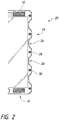
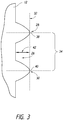
- FIG. 2 there is illustrated a schematic enlargement of the right side 20 of the housing 12.
- the left side may or may not be a mirror image of the right side.
- Right side 20 is provided with a contoured wall 24 having at least one concavity 26 positioned between a first projection 28 and a second projection 30.
- At least one concavity 26, and generally at least about 2, 3, 4, 5 or more may be provided on right side 20.
- four concavities 26 are illustrated.
- An outer boundary 32 is an imaginary line which contacts the apex of each of first projection 28 and second projection 30. In an embodiment where the projections comprise curved surfaces, the outer boundary 32 would describe a tangent with respect to the first projection 28 and second projection 30.
- the width 34 of the concavity 26 may be measured between the tangent contact point 38 and 40 in the implementation illustrated in Figure 3 . In an embodiment in which the projection has a flat surface, such as that illustrated in Figure 1 , the width 34 of the concavity will be measured between the points at which the wall of the concavity fall away from the outer boundary 32 in the direction of the center of the concavity.
- the concavity may also be considered to have a depth 42, measured between the outer boundary 32 and the deepest point in the concavity 26.
- the width 34 of the concavity will generally be at least about 2%, often at least about 4% or 6% and in some embodiments as much as 10% or more of the overall height of the housing 12 measured along the direction of outer boundary line 32. In some implementations, the width 34 may be at least about 30%, and in some implementations, at least about 50% of the height of the housing 12, depending upon the desired performance. In general, the width 34 of each concavity 26 will be at least about 0.25 inches, and often at least about 0.5 inches.
- the depth 42 of the concavity 26, measured at its deepest point, will typically be in excess of about 1 mm, and often at least about 2 mm or 3 mm or more. In some embodiments, the depth 42 will be about 4 or 5 mm, or more.
- the housing illustrated in Figure 1 exhibits bilateral symmetry. However, asymmetrical configurations may be desirable as described below.
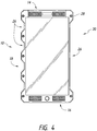
- FIG 4 there is illustrated a cellphone housing as in Figure 1 with a left side 18 and a right side 20. However, the left and right sides exhibit bilateral asymmetry by having fewer concavities 26 on the right side than are present on the left side 18.
- Mirror images of any of the asymmetrical configurations disclosed herein are also contemplated.
- a single right side concavity 26 is defined between a first projection 28 and a second projection 30.
- the single concavity 26 has a width 34 of at least about 30%, and in some implementations at least about 50%, at least about 75% or 85% or more of the overall height of the phone.
- This configuration might be considered to be a phone optimized for right hand operation.
- the anatomy of the hand includes a large rounded mound at the base of the thumb, known as the thenar eminence. This is the result of a grouping of muscles dominated by the abductor pollicis bruvis.
- Providing a concavity 26 having a width of at least about 1 inch, and in some embodiments at least about 1 1 ⁇ 2 inches or 2 inches or 2 1 ⁇ 2 inches or more, provides a cradle for the thenar eminence whereas the multiple distinct concavities 26 on the left side 18 of the housing provide individual cradles for individual fingers.
- the concavity 26 is illustrated in Figure 4 as bilaterally symmetrical about the mid-point of the height of the phone housing, the mid-point of the concavity 26 may be offset in an inferior direction, closer to the bottom edge 16 than the top edge 14.
- the housing for the cellphone may more closely conform to the hand of the user, and the form factor of cellphones in accordance with one or more aspects of at least one of the inventions disclosed herein may take the form of a contoured grip that may be securely grasped by the user.
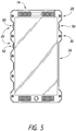
- buttons to control various functions of the phone or other device may be located within one or more of the concavities 26.
- Buttons or other controls may be provided with an activation force threshold that is high enough that the cellphone may be grasped by the user under normal use conditions without activating the button.
- the user can selectively activate the buttons as desired, to control various functions of the telephone.
- a first concavity 26 may be provided with a user activated control such as a button 50, for activation by the index finger.
- a user activated control such as a button 50
- the illustrated cellphone is configured for operation by the user's right hand.
- a second concavity 26 may be provided with a second control 52 for activation by the user's middle finger. Additional buttons (not illustrated) may be provided for the user's ring finger, and baby finger.
- a concavity 26 on the right side of the phone may be provided with a button or other control 54 for activation by the user's thumb.
- the thumb control 54 may be positioned within a concavity 26 defined between a first projection 28 and a second projection 30 that are less than about 2 inches, and preferable less than about 1 inch apart.
- a larger concavity 26 is provided as previously described to provide a cradle for the thenar eminence.
- Embodiments of the concavities 26 of relatively short width may begin to appear to have a corrugated or ridged surface, such as illustrated in Figure 6 .
- An additional example of housing profile is illustrated in Figure 7A , showing a plurality of concavities having substantially constant radius of curvature.
- a hand held device such as a cellular phone having a top edge 14, a bottom edge 16, a left side 18 and a right side 20.
- Each of the left side 18 and right side 20 are provided with a plurality of substantially uniform concavities or undulations, as are discussed in greater detail elsewhere herein.
- the illustrated embodiment exhibits bilateral symmetry, with a first left projection 62 disposed opposite a first right projection 60.
- projection 62 and projection 60 define an opposing projection pair, oriented on a line which is transverse to the longitudinal axis of the phone.
- the first projection pair is located on the top half of the phone, and generally will be within the top 1/3 or top 25% of the overall height of the phone.
- a second right projection 64 may be provided, opposite a second left projection 66. Together, right projections 60 and 64 define the limits of a concavity 26 extending therebetween. Second right projection 64 and second left projection 66 together form a second projection pair, which in turn define a left and right concavity 26 positioned within the top half or top third of the phone.
- the apexes of second right projection 64 and second left projection 66 may define a line which is transverse to the longitudinal axis of the phone, and which may cross the longitudinal axis of the phone at a point within the range of from about ⁇ 30%, in some embodiments within the range of from about ⁇ 15%, and, in some embodiments within about ⁇ 5% of the overall length of the phone from the longitudinal midpoint of the phone.
- a third right projection 68 is disposed opposite a third left projection 70, to define a second pair of concavities 26.
- a fourth right and fourth left projection, and a fifth right and fifth left projection may be provided depending upon the desired functionality of the phone.
- each concavity 26 has a substantially constant radius of curvature, which is generally within the range of from about 0.5 inches to about 2.5 inches, often within the range of about 1.0 inches to about 2.0 inches, and, in one implementation, the radius is within the range of from about 1.3 inches to about 1.8 inches.
- the curvature of the surface within each concavity 26 may be substantially constant, such that the surface curve conforms substantially to a portion of a surface of a circle.
- the curvature of the concavity 26 may be noncircular, such as a surface which conforms to a portion of a surface of an ellipse or toroid.
- radius refers to the radius of a constant radius curve, as well as the radius of a constant radius curve which has the best fit with the non-constant radius curvature of the concavity 26.
- the arc length measured along the surface of the curve of concavity 26 from the apex of adjacent projections will generally be within the range of from about 0.5 inches to about 2.5 inches, often between about 1.0 inches and 2.0 inches, or within about 1.2 inches and about 1.8 inches.
- a line 72 illustrates the width of the phone at the upper edge 14 and lower edge 16, measured in parallel to the longitudinal axis of the phone.
- Line 72 in the illustrated embodiment is a side of the best fit rectangle that encompasses the phone excluding the projections.
- Line 74 illustrates the outer most width boundary of the phone, drawn along a tangent from apex to apex of adjacent projections.
- Concavities 26 may thus represent an area of material which has been removed from the wall of the phone relative to the area of the best fit rectangle surrounding the perimeter of the phone.
- the linear distance between reference line 72 and reference line 74 is generally at least about 0.050 inches, often at least about 0.0625 inches, and preferably at least about 0.125 inches.
- a first plurality of screws or other fasteners 76 may be provided for connecting front and back plates of the phone together. At least 2 and preferably at least 4 or 6 fasteners 76 may conveniently be positioned along the right and left sides 20 and 18 within the projections, thus enabling the fasteners 76 to be carried "off board" so that the width of the viewing surface of the phone may be maximized relative to the overall mass of the phone.
- a second set of fasteners 78 may be provided, with two fasteners located above the viewing screen and two fasteners located below the viewing screen. As such, they may be radially inset towards the midline of the phone without compromising the viewing screen.
- An upper left speaker 80 and upper right speaker 82 may be provided above the viewing screen, as well as a camera lens 84.
- a lower left speaker 83 and a lower right speaker 86 may be provided, as well as at least one microphone may be positioned on the phone, such as below the viewing screen.
- FIG. 7D there is illustrated a perspective view of the embodiment shown in Figure 7B .
- a front plate 90 and a rear plate 92 are spaced apart by an intermediate frame 94 in a sandwich configuration, to enclose the electronics of the phone.
- a plurality of fasteners secure the front plate 90 and rear plate 92 together, to provide an enclosed electronics chamber.
- the camera includes a capability for capturing still images with various and/or adjustable resolutions and aspect ratios for example but without limitation, as high as 6144 x 3160 pixels or higher with aspect ratios such as 2:1, 2.4:1, 16:9, etc, and a capability for capturing motion images at resolutions up to about "6K” or higher including for example, but without limitation, 6K (2:1, 2.4:1), 5K (Full Frame, 2:1, 2.4:1 and Anamorphic 2:1), 4.5K (2.4:1), 4K (16:9, HD, 2:1 and Anamorphic 2:1), 3K (16:9, 2:1 and Anamorphic 2:1), 2K (16:9, 2:1 and Anamorphic 2:1), 1080p RGB (16:9), 720p RGB (16:9) and toher resolutions and formats, depending on the size of the image sensor used in the device 10 and the capacity of the supporting electronics.
- 6K (2:1, 2.4:1) 5K (Full Frame, 2:1, 2.4:1 and Anamorphic 2:1), 4.5K (2.4:1), 4K (16:
- the device 10 can be configured to include a number of compression options, including compressed raw mosaic image sensor data, compressed fully rendered video data and uncompressed video data.
- An onboard memory preferably comprises a capacity of at least about 64GB, and, in one implementation, at least about 128GB.
- the phone includes a slot or cavity for receiving at least one, and preferably two or more SIM cards, to enable the phone to receive two or more phone numbers. Two cameras are provided, one facing outwardly from the front of the phone and one facing outwardly from the rear of the phone.
- the device 10 can include one or more lights which, optionally, can be used for personal lighting (e.g., flashlight) or photographic purposes.
- the device 10 can include a camera lens 84.
- the device 10 can include a lighting device 200 disposed on the front side of the device 10, facing the same direction as the lens 84.
- the lighting device 200 can be any type of lighting device, and in some embodiments, is configured for high intensity "flash" output such as that used for "flash photography". Additionally, in some embodiments, the lighting device 200 can also be configured for continuous operation, such as in a flashlight mode for providing lighting as desired by user.
- the lighting device 200 can be configured for continuous operation during use of the camera lens 84 for recording motion video.
- the lighting device 200 can be in the form of one or plurality of LEDs. The design and operation of this type of lighting device, including those designs based on LEDs, is well known in the art.
- the lighting device 200 can extend around the periphery of the camera lens 84 in connection with a first camera 151, described below with reference to Figure 8 .
- the lighting device 200 can provide an effect similar to that provided by lighting devices known as "ring lights” or "ring flashes".
- the lighting device 200 can be constructed using two or more light emitting devices, such as LEDs, and an optical diffuser such as a transparent material with a frosted surface application.
- the lighting device 200 can include light emitting devices configured to be adjustable as to the color or temperature of light emitted therefrom.
- the light emitting devices included within the lighting device 200 can be configured to emit different "temperatures" of white light typically used for photography.
- the lighting device 200 can be configured to emit a large range of different colors of light, for example, using "RGB” LEDs light emitting devices. Such LED devices as well as the operation control of which are widely known and commercially available.
- the device 10 can include a lighting device 202.
- the lighting device 202 can include a circumferentially extending configuration.
- the lighting device 202 can extend around the display 22.
- the lighting device 202 can be constructed with a plurality of light emitting devices, such as LEDs, which can be white, adjustable within a range of temperatures of white colors, or a broad range of colors such as "RGB" LED lighting devices.
- the lighting device 202 can be configured for control is a "flash" mode for photography, in a flashlight mode, or other modes for continuous or substantially continuous output of light for personal lighting applications such as recording motion video as desired.
- the device 10 can include programming for operating the lighting device 202 for further entertainment purposes, such as light changing schemes which may or may not be synchronized with audio output from the device 10. Such control options and techniques are well known in the art.
- the device 10 can also include a lighting device 204.
- the lighting device 204 can be disposed along the peripheral edge of the device 10. In the illustrated embodiment, the lighting device 204 follows along the shape of the outer periphery of the vice 10 and that includes or defines part of the concavities 26.
- the lighting device 204 can include a plurality of light emitting devices, such as LEDs, covered with a translucent cover for diffusing light emitted by the light imaging devices.
- the device 10 can include light imaging devices placed atop one or more of the screws 76 described above.
- the backside of the device 10 can include a camera lens 85, for example, for use in conjunction with a second camera 152, described below with reference to Figure 8 .
- the device 10 can also include a light lighting device 206 disposed partially or entirely around a periphery of the lens 85.
- the device 10 can include a lighting device 208 extending around a periphery of the backside of the device 10.
- the lighting device 208 can be constructed in a similar or identical fashion to the lighting devices 200, 202, or two of four noted above.
- a lighting device with a more diffused light emission characteristics, such as that resulting from the ring-shaped lighting devices 200, 206 or the more rectangular lighting devices 202, 204, 208 or even the use of a plurality of lighting devices disposed at a plurality of points relative to a camera lens, such as the camera lens 84, 85, different lighting aesthetics can be achieved.
- the use of more diffused lighting can provide enhanced and or more desirable results, for example, by generating shadows with softer edges, and/or other effects.
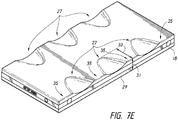
- the device 10 can include concavities 27 which do not extend onto the front side of the device 10.
- Figure 7E illustrates an alternative embodiment in which the concavities 26 are in the form of concavities 27 defined in the back surface of the device 10 as well as one or both of the sides 18, 20.
- Figure 7E illustrates a plurality of concavities 27 which are defined partly on the backside of the device 10 and on the left side 18.
- an edge 29 between the left side 18 in the front side of the device 10 extends along a generally straight line. That is because, in the illustrated embodiment, the concavities 27 do not extend beyonf the edge 29 or onto the front side of the device 10.
- the embodiment of the device 10 illustrated in Figure 7E would appear to be rectangular in a top plan view, in other words, the concavities 27 would generally not be visible in a top plan view of the front side (the view corresponding to Figure 7A ).
- the concavities 27 can have a maximum depth 31 of approximately 75% of the thickness of the device 10, however, other depths can also be used. Additionally, the concavities 27 can have a length 33 smaller than the magnitude of the depth 31, approximately the same magnitude as the depth 31, or up to 2 to 3 times the magnitude of the depth 31. However, other configurations of the concavities 27 can also be used. In the context of the embodiment of Figure 7E , the raised areas adjacent to the concavities 27 can be considered as forming projections 35 on the left side 18, defining the concavities 27 therebetween.
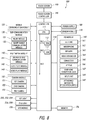
- FIG. 8 is a block diagram illustrating various additional electronic aspects and features of a device according to an embodiment of the present disclosure.
- the housing of the embodiments described above may be utilized with electronic devices having any of a variety of features, and the following is illustrative only and not limiting on the present inventions. Additional details of potential electronic aspects can be found, for example, in document US 2014/0055394 which discloses in particular a flexible device includes a flexible body and a plurality of piezoelectric materials arranged on the flexible body that deform in response to drive signals causing deformation of the flexible body of the flexible device.
- an electronic device 100 such as a cellphone in accordance with an embodiment may be connected to an external device by using an external connection device, such as a sub-communication module 130, a connector 165, and an earphone connecting jack 167.
- the "external device” may include a variety of devices, such as earphones, external speakers, Universal Serial Bus (USB) memories, chargers, cradles/docks, Digital Multimedia Broadcasting (DMB) antennas, electronic payment related devices, health care devices (e.g., blood sugar testers), game consoles, vehicle navigations, and the like, which are removable from the electronic device and connected thereto via a cable.
- USB Universal Serial Bus
- DMB Digital Multimedia Broadcasting
- the “external device” may also include a short range communication device that may be wirelessly connected to the electronic device 100 via short range communication, such as BLUETOOTH, a short range wireless communications technology at the 2.4 GHz band, commercially available from the BLUETOOTH SPECIAL INTEREST GROUP, INC., a Near Field Communication (NFC), and the like, and a communication device using WI-FI DIRECT, a wireless technology for data exchange over a computer network, commercially available from the WI-FI ALLIANCE, a wireless Access Point (AP), and the like.
- the external device may include any other device, such as a cell phone, a smartphone, a tablet PC, a desktop PC, a server, and the like.
- the electronic device 100 includes a display unit 190 and a display controller 195.
- the electronic device 100 also includes a controller 110, a mobile communication module 120, the sub-communication module 130, a multimedia module 140, a camera module 150, a Global Positioning System (GPS) module 155, an input/output module 160, a sensor module 170, a storage 175, and a power supply 180.
- the sub-communication module 130 includes at least one of Wireless Local Area Network (WLAN) 131 and a short-range communication module 132
- the multimedia module 140 includes at least one of a broadcast communication module 141, an audio play module 142, and a video play module 143.
- WLAN Wireless Local Area Network
- the multimedia module 140 includes at least one of a broadcast communication module 141, an audio play module 142, and a video play module 143.
- the camera module 150 includes at least one of a first camera 151, a second camera 152, a third camera 153 and the input/output module 160 includes at least one of buttons 161, a microphone 162, a speaker 163, a vibration motor 164, the connector 165, and a keypad 166.
- the second and third cameras 152, 153 can both be disposed on the backside of the device 10, so to accommodate various types of photographic tools, including 3-D still photography or motion video, as well as other types of effects.
- the electronic device 100 can include one or more lights, for example, the lights 200, 202, 204 described above are schematically illustrated as a "first light”. Additionally, the lighting devices 206, 208 are schematically illustrated as a "second light”.
- the controller 110 may include a Central Processing Unit (CPU) 111, a Read Only Memory (ROM) 112 for storing a control program, such as an Operating System (OS), to control the electronic device 100, and a Random Access Memory (RAM) 113 for storing signals or data input from an external source or for being used as a memory space for working results in the electronic device 100.
- the CPU 111 may include a single core, dual cores, triple cores, or quad cores.
- the CPU 111, ROM 112, and RAM 113 may be connected to each other via an internal bus.
- the controller 110 may control the mobile communication module 120, the sub-communication module 130, the multimedia module 140, the camera module 150, the GPS module 155, the input/output module 160, the sensor module 170, the storage 175, the power supply 180, the display unit 190, and the display controller 195.
- the mobile communication module 120 connects the electronic device 100 to an external device through mobile communication using at least a one-to-one antenna or a one-to-many antenna under the control of the controller 110.
- the mobile communication module 120 transmits/receives wireless signals for voice calls, video conference calls, Short Message Service (SMS) messages, or Multimedia Message Service (MMS) messages to/from a cell phone, a smartphone, a tablet PC, or another device, with the phones having phone numbers entered into the electronic device 100.
- SMS Short Message Service
- MMS Multimedia Message Service
- the sub-communication module 130 may include at least one of the WLAN module 131 and the short-range communication module 132.
- the sub-communication module 130 may include either the WLAN module 131 or the-short range communication module 132, or both.
- the WLAN module 131 may be connected to the Internet in a place where there is a wireless Access Point (AP), under the control of the controller 110.
- the WLAN module 131 supports the WLAN Institute of Electrical and Electronic Engineers (IEEE)802.11x standard.
- the short-range communication module 132 may conduct short-range communication between the electronic device 100 and an image rendering device under the control of the controller 110.
- the short-range communication may include communications compatible with BLUETOOTH, a short range wireless communications technology at the 2.4 GHz band, commercially available from the BLUETOOTH SPECIAL INTEREST GROUP, INC., Infrared Data Association (IrDA), WI-FI DIRECT, a wireless technology for data exchange over a computer network, commercially available from the WI-FI ALLIANCE, NFC, and the like.
- BLUETOOTH a short range wireless communications technology at the 2.4 GHz band
- BLUETOOTH SPECIAL INTEREST GROUP INC.
- IrDA Infrared Data Association
- WI-FI DIRECT wireless technology for data exchange over a computer network
- the electronic device 100 may include at least one of the mobile communication module 120, the WLAN module 131, and the short-range communication module 132 based on the performance requirements of the electronic device 100.
- the electronic device 100 may include a combination of the mobile communication module 120, the WLAN module 131, and the short-range communication module 132 based on the performance requirements of the electronic device 100.
- the multimedia module 140 may include the broadcast communication module 141, the audio play module 142, or the video play module 143.
- the broadcast communication module 141 may receive broadcast signals (e.g., television broadcast signals, radio broadcast signals, or data broadcast signals) and additional broadcast information (e.g., an Electric Program Guide (EPG) or an Electric Service Guide (ESG)) transmitted from a broadcasting station through a broadcast communication antenna under the control of the controller 110.
- the audio play module 142 may play digital audio files (e.g., files having extensions, such as mp3, wma, ogg, or way) stored or received under the control of the controller 110.
- the video play module 143 may play digital video files (e.g., files having extensions, such as mpeg, mpg, mp4, avi, move, or mkv) stored or received under the control of the controller 110.
- the video play module 143 may also play digital audio files.
- the multimedia module 140 may include the audio play module 142 and the video play module 143 except for the broadcast communication module 141.
- the audio play module 142 or video play module 143 of the multimedia module 140 may be included in the controller 110.
- the camera module 150 may include at least one of the first camera 151 and the second camera 152 for capturing still images or video images under the control of the controller 110. Furthermore, the first or second camera 151 or 152, respectively, may include an auxiliary light source (e.g., a flash) for providing an amount of light for capturing an image.
- the first camera 151 may be placed on the front of the electronic device 100 and the second camera 152 may be placed on the back of electronic device 100.
- the first and second cameras 151 and 152, respectively are arranged adjacent to each other (e.g., the distance between the first and second cameras 151 and 152, respectively, may be in the range of 1 cm. to 8 cm.), capturing 3 Dimensional (3D) still images or 3D video images.
- the GPS module 155 receives radio signals from a plurality of GPS satellites in orbit around the Earth, and may calculate the position of the electronic device 100 by using time of arrival from the GPS satellites to the electronic device 100.
- the input/output module 160 may include at least one of the plurality of buttons 161, the microphone 162, the speaker 163, the vibrating motor 164, the connector 165, and the keypad 166.
- the at least one of the buttons 161 may be arranged on the front, side or back of the housing of the electronic device 100, and may include at least one of a power/lock button, a volume button, a menu button, a home button, a back button, and a search button.
- the microphone 162 generates electric signals by receiving voice or sound under the control of the controller 110.
- the speaker 163 may output sounds externally corresponding to various signals (e.g., radio signals, broadcast signals, digital audio files, digital video files or photography signals) from the mobile communication module 120, sub-communication module 130, multimedia module 140, or camera module 150 under the control of the controller 110.
- the speaker 163 may output sounds (e.g., button-press sounds or ringback tones) that correspond to functions performed by the electronic device 100.
- the vibrating motor 164 may convert an electric signal to a mechanical vibration under the control of the controller 110.
- the electronic device 100 in a vibrating mode operates the vibrating motor 164 when receiving a voice call from another device.
- the vibration motor 164 may operate in response to a touch activity or continuous touches of a user over the display unit 190.
- the connector 165 may be used as an interface for connecting the electronic device 100 to the external device or a power source. Under the control of the controller 110, the electronic device 100 may transmit data stored in the storage 175 of the electronic device 100 to the external device via a cable connected to the connector 165, or receive data from the external device. Furthermore, the electronic device 100 may be powered by the power source via a cable connected to the connector 165 or may charge the battery using the power source.
- the keypad 166 may receive key inputs from the user to control the electronic device 100.
- the keypad 166 includes a mechanical keypad formed in the electronic device 100, or a virtual keypad displayed on the display unit 190.
- the mechanical keypad formed in the electronic device 100 may optionally be omitted from the implementation of the electronic device 100, depending on the performance requirements or structure of the electronic device 100.
- An earphone may be inserted into the earphone connecting jack 167 and thus, may be connected to the electronic device 100.
- a stylus pen 168 may be inserted and removably retained in the electronic device 100, and may be drawn out and detached from the electronic device 100.
- a pen-removable recognition switch 169 that operates in response to attachment and detachment of the stylus pen 168 is equipped in an area inside the electronic device 100 where the stylus pen 168 is removably retained, and sends a signal that corresponds to the attachment or the detachment of the stylus pen 168 to the controller 100.
- the pen-removable recognition switch 169 may have a direct or indirect contact with the stylus pen 168 when the stylus pen 168 is inserted into the area.
- the pen-removable recognition switch 169 generates the signal that corresponds to the attachment or detachment of the stylus pen 168 based on the direct or indirect contact and provides the signal to the controller 110.
- the sensor module 170 includes at least one sensor for detecting a status of the electronic device 100.
- the sensor module 170 may include a proximity sensor for detecting proximity of a user to the electronic device 100, an illumination sensor for detecting an amount of ambient light of the electronic device 100, a motion sensor for detecting the motion of the electronic device 100 (e.g., rotation of the electronic device 100, acceleration or vibration applied to the electronic device 100), a geomagnetic sensor for detecting a point of the compass using the geomagnetic field, a gravity sensor for detecting a direction of gravity, and an altimeter for detecting an altitude by measuring atmospheric pressure.
- At least one sensor may detect the status and generate a corresponding signal to transmit to the controller 110.
- the sensor of the sensor module 170 may be added or removed depending on the performance requirements of the electronic device 100 of the electronic device 100.
- the storage 175 may store signals or data input/output according to operations of the mobile communication module 120, the sub-communication module 130, the multimedia module 140, the camera module 150, the GPS module, the input/output module 160, the sensor module 170, the display unit 190 under the control of the controller 110.
- the storage 175 may store the control programs and applications for controlling the electronic device 100 or the controller 110.
- the term “storage” refers to the storage 175, and also to the ROM 112, RAM 113 in the controller 110, or a memory card (e.g., a Secure Digital (SD) card, a memory stick, and the like) installed in the electronic device 100.
- the storage may also include a non-volatile memory, a volatile memory, a Hard Disc Drive (HDD), a Solid State Drive (SSD), or the like.
- the power supply 180 may supply power to at least one battery placed inside the housing of the electronic device 100 under the control of the controller 110.
- the at least one battery powers the electronic device 100.
- the power supply 180 may supply the electronic device 100 with the power input from the external power source via a cable connected to the connector 165.
- the power supply 180 may also supply the electronic device 100 with wireless power from an external power source using a wireless charging technology.
- the display controller 195 receives information (e.g., information to be generated for making calls, data transmission, broadcast, or photography) that is processed by the controller 110, converts the information to data to be displayed on the display unit 190, and provides the data to the display unit 190.
- the display unit 190 displays the data received from the display controller 195.
- the display unit 190 may display a User Interface (UI) or a Graphic User Interface (GUI) with respect to a call.
- UI User Interface
- GUI Graphic User Interface
- the display unit 190 may include at least one of liquid crystal displays, thin film transistor-liquid crystal displays, organic light-emitting diodes, flexible displays, 3D displays, electrophoretic displays, and the like.
- the display unit 190 may be used as an output device and also as an input device, and for the latter case, may have a touchscreen panel to operate as a touch screen.
- the display unit 190 may send to the display controller 195 an analog signal that corresponds to at least one touch to the UI or GUI.
- the display unit 190 may detect the at least one touch by a user's physical contact (e.g., by fingers including a thumb) or by a touchable input device (e.g., the stylus pen).
- the display unit 190 may also receive a dragging movement of a touch among at least one touch and transmit an analog signal that corresponds to the dragging movement to the display controller 195.
- the display unit 190 may be implemented to detect at least one touch in, for example, a resistive method, a capacitive method, an infrared method, an acoustic wave method, or the like.
- touches are not limited to physical touches by a physical contact of the user or contacts with the touchable input device, but may also include touchless proximity (e.g., maintaining a detectable distance less than 1 mm. between the display unit 190 and the user's body or touchable input device).
- the detectable distance from the display unit 190 may vary depending on the performance requirements of the electronic device 100 or structure of the electronic device 100, and more particularly, the display unit 190 may output different values (e.g., current values) for touch detection and hovering detection to distinguishably detect that a touch event occurred by a contact with the user's body or the touchable input device and a contactless input (e.g., a hovering event).
- the display unit 190 may output different values (e.g., current values) for hovering detection over distance from where the hovering event occurs.
- the display controller 195 converts the analog signal received from the display unit 190 to a digital signal (e.g., in XY coordinates on the touch panel or display screen) and transmits the digital signal to the controller 110.
- the controller 110 may control the display unit 190 by using the digital signal received from the display controller 195. For example, in response to the touch event or the hovering event, the controller 110 may enable a shortcut icon displayed on the display unit 190 to be selected or to be executed.
- the display controller 195 may also be incorporated in the controller 110.
- the display controller 195 may determine the distance between where the hovering event occurs and the display unit 190 by detecting a value (e.g., a current value) output through the display unit 190, convert the determined distance to a digital signal (e.g., with a Z coordinate), and provide the digital signal to the controller 110.
- a value e.g., a current value
- a digital signal e.g., with a Z coordinate
- the electronic device 100 may have two or more display units.
- the display unit 190 may include at least two touchscreen panels for detecting touches or proximity thereto by the user's body or the touchable input device to receive both inputs by the user's body or the touchable input device simultaneously.
- the at least two touchscreen panels provide different output values to the display controller 195, and the display controller 195 may differentiate inputs by the user's body and inputs by the touchable input device through the touchscreen by differently recognizing the values input from the at least two touchscreen panels.
- any of the handheld electronic devices described herein, including those described with respect to Figures 1-7E can incorporate some or all of the components and corresponding functionality shown and described with respect to Figure 8 .
- certain electronic devices shown and described herein are cellphones
- other handheld electronic device embodiments are not cellphones, and do not include telephonic capability.
- some embodiments have the same or similar exterior as the devices shown and described with respect to any of Figures 1-7E , but do not include telephonic capability, such as in the case of a tablet computing device or digital camera.
- Such embodiments may nonetheless include any combination of the non-telephone components and functionality described with respect to Figure 8 , such as one or more of the following or portions thereof: controller 110, touch screen 190 and touch screen controller 195, camera module 150, multi-media module 140, sub-communication module 130, first light 200, 202, 204, second light 206, 208, GPS module 155, I/O module 160, and memory 176.
- a phrase referring to "at least one of' a list of items refers to any combination of those items, including single members.
- "at least one of: a, b, or c” is intended to cover: a, b, c, a-b, a-c, b-c, and a-b-c.
- a processor may be a microprocessor, or, any processor, controller, microcontroller, or state machine.
- a processor also may be implemented as a combination of electronic devices, such as a combination of a DSP and a microprocessor, a plurality of microprocessors, one or more microprocessors in conjunction with a DSP core, or any other such configuration.
- particular steps and methods may be performed by circuitry that is specific to a given function.
- the functions described may be implemented in hardware, digital electronic circuitry, computer software, firmware, including the structures disclosed in this specification and their structural equivalents thereof, or in any combination thereof. Implementations of the subject matter described in this specification also can be implemented as one or more computer programs, e.g., one or more modules of computer program instructions, encoded on a computer storage media for execution by, or to control the operation of, data processing apparatus.
- Computer-readable media includes both computer storage media and communication media including any medium that can be enabled to transfer a computer program from one place to another. Storage media may be any available media that may be accessed by a computer.
- Such computer-readable media may include RAM, ROM, EEPROM, CD-ROM or other optical disk storage, magnetic disk storage or other magnetic storage devices, or any other medium that may be used to store desired program code in the form of instructions or data structures and that may be accessed by a computer.
Claims (17)
- Dispositif de communication mobile (10) doté de structures de surface de préhension améliorées, le dispositif de communication mobile comprenant :un corps (12) présentant un bord supérieur (14) et un bord inférieur (16) opposé au bord supérieur (14), une surface avant avec un écran d'affichage (22), une surface arrière, un premier côté (20) doté de structures de surface de préhension améliorées qui comprennent au moins trois extensions (28, 30) faisant saillie à partir du premier côté (20) lesquelles définissent au moins des première et seconde concavités (26) du premier côté (20), et un second côté (18), le corps (12) présentant en outre une moitié supérieure définie entre une partie centrale du corps (12) et le bord supérieur (14), et une moitié inférieure définie entre la partie centrale et le bord inférieur (16) ;dans lequel au moins la première concavité (26) du premier côté (20) est positionnée dans la moitié supérieure du corps ;dans lequel au moins la seconde concavité (26) du premier côté (20) est positionnée dans la moitié inférieure du corps (12) ; etdans lequel les première (26) et seconde (26) concavités du premier côté (20) présentent une largeur d'au moins 1,27 cm et un rayon de courbure constant dont la plage est comprise entre 1,27 cm et 5,08 cm.
- Dispositif de communication mobile doté de structures de surface de préhension améliorées selon la revendication 1, dans lequel le second côté (18) du corps (12) est pourvu des structures de surface de préhension améliorées qui comprennent en outre au moins trois extensions faisant saillie à partir du second côté lesquelles définissent au moins des première et seconde concavités du second côté.
- Dispositif de communication mobile doté de structures de surface de préhension améliorées selon la revendication 2, dans lequel au moins la première concavité (26) du premier côté (20) et la première concavité (26) du second côté (18) définissent une première paire de concavités positionnées dans la moitié supérieure du corps, et au moins la seconde concavité du premier côté et la seconde concavité du second côté définissent une seconde paire de concavités positionnées dans la moitié inférieure du corps (12).
- Dispositif de communication mobile doté de structures de surface de préhension améliorées selon la revendication 2, dans lequel les première et seconde concavités (26) du second côté (18) présentant une largeur d'au moins 1,27 cm et un rayon de courbure constant dont la plage est comprise entre 1,27 cm et 5,08 cm.
- Dispositif de communication mobile doté de structures de surface de préhension améliorées selon la revendication 1, dans lequel lesdites au moins trois extensions (28, 30) faisant saillie à partir du premier côté (20) sont fixées d'un seul tenant au corps (12) et la première concavité (26) présente une première largeur dont la hauteur correspond à au moins 30 % de la hauteur du corps (12).
- Dispositif de communication mobile doté de structures de surface de préhension améliorées selon la revendication 1, dans lequel le corps (12) présente un cadre intermédiaire positionné entre la surface avant et la surface arrière.
- Dispositif de communication mobile doté de structures de surface de préhension améliorées selon la revendication 1, dans lequel les première et seconde concavités du premier côté (20) sont espacées symétriquement sur une longueur du dispositif de communication mobile.
- Dispositif de communication mobile doté de structures de surface de préhension améliorées selon la revendication 2, dans lequel un nombre de concavités du premier côté (20) est différent d'un nombre de concavités du second côté (18).
- Dispositif de communication mobile doté de structures de surface de préhension améliorées selon la revendication 1, dans lequel l'écran d'affichage comprend un affichage à écran tactile (22).
- Dispositif de communication mobile selon la revendication 1, dans lequel le second côté (18) du boîtier comprend au moins deux saillies exposées qui définissent au moins une concavité intermédiaire du second côté.
- Dispositif de communication mobile selon la revendication 10, dans lequel ladite au moins une concavité du second côté (18) présente une largeur d'au moins 1,27 cm, et ladite au moins une concavité des premier et second côtés fournit les structures de surface de préhension améliorées pour le boîtier.
- Dispositif de communication mobile selon la revendication 10, comprenant en outre une caméra située au sein du boîtier, le boîtier comprenant en outre une surface avant et une surface arrière, la caméra comprenant un objectif de caméra (84) exposé sur la surface avant ou la surface arrière.
- Dispositif de communication mobile selon la revendication 10, dans lequel au moins une concavité (26) sélectionnée à partir du groupe constitué par ladite au moins une concavité du premier côté (20) et ladite au moins une concavité du second côté (18) présente une profondeur d'au moins 0,15875 cm.
- Dispositif de communication mobile selon la revendication 10, dans lequel ladite au moins une concavité des premier (20) et second (18) côtés présente une profondeur d'au moins 0,3175 cm.
- Dispositif de communication mobile selon la revendication 10, dans lequel ladite au moins une concavité des premier (20) et second (18) côtés présente un rayon de courbure constant.
- Dispositif de communication mobile selon la revendication 15, dans lequel le rayon de courbure constant présente une plage allant de 1,27 cm à 5,08 cm.
- Dispositif de communication mobile selon la revendication 10, comprenant un affichage à écran tactile (22) qui définit une surface frontale du dispositif de communication mobile.
Applications Claiming Priority (3)
| Application Number | Priority Date | Filing Date | Title |
|---|---|---|---|
| US201461947889P | 2014-03-04 | 2014-03-04 | |
| US14/247,160 US9621690B2 (en) | 2014-03-04 | 2014-04-07 | Cellphone with contoured surfaces |
| PCT/US2015/018125 WO2015134329A1 (fr) | 2014-03-04 | 2015-02-27 | Dispositif électronique portatif avec surfaces modelées |
Publications (2)
| Publication Number | Publication Date |
|---|---|
| EP3114824A1 EP3114824A1 (fr) | 2017-01-11 |
| EP3114824B1 true EP3114824B1 (fr) | 2020-02-12 |
Family
ID=54018642
Family Applications (1)
| Application Number | Title | Priority Date | Filing Date |
|---|---|---|---|
| EP15710047.0A Active EP3114824B1 (fr) | 2014-03-04 | 2015-02-27 | Dispositif de communication mobile avec surfaces modelées |
Country Status (9)
| Country | Link |
|---|---|
| US (2) | US9621690B2 (fr) |
| EP (1) | EP3114824B1 (fr) |
| JP (2) | JP2017511633A (fr) |
| KR (1) | KR20160129892A (fr) |
| CN (1) | CN106133633A (fr) |
| CA (1) | CA2940816A1 (fr) |
| MX (1) | MX367189B (fr) |
| TW (2) | TW201541928A (fr) |
| WO (1) | WO2015134329A1 (fr) |
Families Citing this family (27)
| Publication number | Priority date | Publication date | Assignee | Title |
|---|---|---|---|---|
| US9917935B2 (en) | 2014-03-04 | 2018-03-13 | Houdinix Llc | Multi-layer handheld electronic device |
| US9621690B2 (en) * | 2014-03-04 | 2017-04-11 | Houdinix Llc | Cellphone with contoured surfaces |
| USD763250S1 (en) | 2014-04-04 | 2016-08-09 | Houdinix Llc | Electronic device |
| US9857570B1 (en) * | 2014-07-24 | 2018-01-02 | Hoyos Integrity Corporation | Full flat mirror guiding reflections to aperture of panoramic optical device |
| CN104197299A (zh) * | 2014-08-21 | 2014-12-10 | 浙江生辉照明有限公司 | 照明装置及基于该装置的语音播报系统及方法 |
| TWD172866S (zh) * | 2014-08-27 | 2016-01-01 | 鴻海精密工業股份有限公司 | 行動電話保護套之部分 |
| CN105578821A (zh) * | 2014-10-13 | 2016-05-11 | 联想(北京)有限公司 | 电子设备及其壳体的制备方法 |
| JP2019507996A (ja) | 2015-12-14 | 2019-03-22 | レッド.コム,エルエルシー | モジュール式デジタルカメラおよび携帯電話 |
| US10551598B2 (en) * | 2016-01-06 | 2020-02-04 | Panavision International, L.P. | Anamorphic photography for digital imagers |
| CN105446058B (zh) | 2016-01-07 | 2019-03-22 | 林璧光 | 一种直照式和柔光式可变换的拍摄用led照明灯 |
| KR101809962B1 (ko) | 2016-03-30 | 2017-12-18 | 엘지전자 주식회사 | 이동 단말기 및 그 제조방법 |
| CN105847483A (zh) * | 2016-05-27 | 2016-08-10 | 广东欧珀移动通信有限公司 | 移动终端 |
| DE102016113269A1 (de) * | 2016-07-19 | 2018-01-25 | Osram Opto Semiconductors Gmbh | Leuchtvorrichtung für ein mobiles endgerät |
| USD825571S1 (en) * | 2016-11-16 | 2018-08-14 | BobjGear, LLC | Electronic device cover with fingerswipe indentation |
| USD886088S1 (en) | 2017-06-30 | 2020-06-02 | Red.Com, Llc. | Electronic device |
| US10539764B2 (en) | 2017-07-05 | 2020-01-21 | Panavision International, L.P. | Anamorphic photography and squeeze ratios for digital imagers |
| WO2019010233A1 (fr) | 2017-07-05 | 2019-01-10 | Red. Com, Llc | Traitement de données d'image vidéo dans des dispositifs électroniques |
| USD838195S1 (en) * | 2017-08-24 | 2019-01-15 | Shenzhen Foxwell Technology Co., Ltd. | Diagnostic code reader |
| JP2019122000A (ja) * | 2018-01-11 | 2019-07-22 | 株式会社東海理化電機製作所 | 携帯機 |
| USD881884S1 (en) * | 2018-03-21 | 2020-04-21 | Yehuda Goltche | Control pad |
| USD873785S1 (en) | 2018-05-18 | 2020-01-28 | Red Hydrogen Llc | Electronic device |
| JP6773736B2 (ja) | 2018-09-12 | 2020-10-21 | ファナック株式会社 | 携帯端末に取り付けられる枠部材、枠部材を備える機械の操作装置、および携帯端末のコンピュータプログラム |
| KR20200094950A (ko) * | 2019-01-31 | 2020-08-10 | 삼성전자주식회사 | 금속 물질을 포함하는 하우징을 포함하는 전자 장치 |
| USD915397S1 (en) * | 2019-07-05 | 2021-04-06 | Ultra Electronics Limited | Computer |
| USD901479S1 (en) * | 2019-07-26 | 2020-11-10 | Catalyst Medium Four, Inc. | Case for a mobile communications device |
| USD901480S1 (en) * | 2019-07-26 | 2020-11-10 | Catalyst Medium Four, Inc. | Case for a mobile communications device |
| USD954694S1 (en) * | 2020-12-11 | 2022-06-14 | Randall Barfield | Phone grip accessory |
Citations (1)
| Publication number | Priority date | Publication date | Assignee | Title |
|---|---|---|---|---|
| US5805474A (en) * | 1989-06-08 | 1998-09-08 | Norand Corporation | Portable work station type-data collection system having an improved handgrip and an optical reader to be directed thereby |
Family Cites Families (92)
| Publication number | Priority date | Publication date | Assignee | Title |
|---|---|---|---|---|
| USD244209S (en) | 1975-09-16 | 1977-05-03 | Bliven Robert P | Telephone |
| USD270062S (en) | 1980-11-08 | 1983-08-09 | Licinvest Ag | Picture viewer |
| USD274674S (en) | 1981-11-18 | 1984-07-17 | `Totes`, Incorporated | Umbrella handle |
| USD279673S (en) | 1983-02-28 | 1985-07-16 | Marvin Glass & Associates | Telephone |
| USD319059S (en) | 1988-03-22 | 1991-08-13 | Rainsinger Enterprises, Inc. | Combined radio and umbrella handle |
| USD316409S (en) | 1989-11-16 | 1991-04-23 | PhoneMate | Cordless handset telephone |
| USD316410S (en) | 1990-02-21 | 1991-04-23 | Oki Electric Industry Co., Ltd. | Portable radio telephone |
| JP3099496B2 (ja) * | 1992-02-14 | 2000-10-16 | 株式会社日立製作所 | 携帯用無線電話機 |
| US5371790A (en) | 1992-07-31 | 1994-12-06 | Canetti Nicolai | Telephone with resilient housing |
| USD357918S (en) | 1992-12-28 | 1995-05-02 | Daniels S.R.L. | Protective rim for remote controls |
| US5925873A (en) | 1993-07-23 | 1999-07-20 | Khyber Technologies Corporation | Grip held and grip operable data entry device |
| USD357256S (en) | 1993-08-11 | 1995-04-11 | Jardine John A | Combined stereo converter and remote control |
| USD352936S (en) | 1993-10-07 | 1994-11-29 | Psc, Inc. | Optical scanner |
| USD358177S (en) | 1994-06-17 | 1995-05-09 | International Business Machines Corporation | Display panel |
| US5805256A (en) | 1995-02-27 | 1998-09-08 | Miller; William | Remote control with a thumbswitch for controlling equipment that handles video or audio signals |
| USD375950S (en) | 1995-11-16 | 1996-11-26 | Elcom Technologies Corporation | Electronic transceiver |
| USD380449S (en) | 1996-04-18 | 1997-07-01 | Dennis Palatov | Remote control unit with thumb-operated pointer |
| USD407396S (en) | 1997-05-30 | 1999-03-30 | Sony Corporation | Wireless telephone |
| USD418132S (en) | 1997-09-26 | 1999-12-28 | Harris Corporation | Telecommunications test set |
| JP3289689B2 (ja) * | 1998-11-11 | 2002-06-10 | 日本電気株式会社 | キーボード装置 |
| JP2000299725A (ja) * | 1999-04-13 | 2000-10-24 | Matsushita Electric Ind Co Ltd | 携帯電話機 |
| USD427983S (en) | 1999-07-09 | 2000-07-11 | Matsushita Electric Industrial Co., Ltd. | Mobile phone |
| USD427172S (en) | 1999-08-19 | 2000-06-27 | Bequir Kevin A | Portable telephone |
| US6164853A (en) | 1999-09-09 | 2000-12-26 | Foote; Lisa L. | Ergonomic housing for a handheld device |
| JP2001251400A (ja) | 2000-03-03 | 2001-09-14 | Matsushita Electric Ind Co Ltd | 携帯電話機 |
| JP2001336965A (ja) * | 2000-05-29 | 2001-12-07 | Kao Corp | 洗剤用計量スプーン |
| USD460059S1 (en) | 2000-06-20 | 2002-07-09 | Vtech Communications, Ltd. | Telephone handset |
| JP2002222036A (ja) * | 2001-01-25 | 2002-08-09 | Mitsubishi Electric Corp | 携帯情報端末 |
| JP2002353640A (ja) * | 2001-05-29 | 2002-12-06 | Sony Corp | 保持装置 |
| US6925315B2 (en) | 2001-10-30 | 2005-08-02 | Fred Langford | Telephone handset with thumb-operated tactile keypad |
| USD459712S1 (en) | 2001-11-14 | 2002-07-02 | Fred Langford | Cell phone |
| US6822852B2 (en) * | 2001-12-18 | 2004-11-23 | Qualcomm, Incorporated | Handheld devices |
| AU2003232893A1 (en) * | 2002-01-29 | 2003-06-30 | Yuri Borisovich Pilipishin | Palmar device for controlling an electronic instrument (variants) |
| USD480375S1 (en) | 2002-06-20 | 2003-10-07 | Motorola, Inc. | Portable communication device |
| USD492297S1 (en) | 2002-10-31 | 2004-06-29 | Nokia Corporation | Key button arrangement for a handset |
| USD487440S1 (en) | 2003-02-27 | 2004-03-09 | Fred Langford | Cell phone |
| USD487442S1 (en) | 2003-04-30 | 2004-03-09 | Quanta Computer, Inc. | Cellular phone |
| USD496635S1 (en) | 2003-07-09 | 2004-09-28 | Motorola, Inc. | Communication device |
| JP2005112383A (ja) * | 2003-10-06 | 2005-04-28 | Toyo Seikan Kaisha Ltd | 容器 |
| US7023700B2 (en) | 2003-12-24 | 2006-04-04 | Super Talent Electronics, Inc. | Heat sink riveted to memory module with upper slots and open bottom edge for air flow |
| USD511773S1 (en) | 2004-04-05 | 2005-11-22 | Matsushita Electic Industrial Co., Ltd. | Personal digital assistant |
| USD528110S1 (en) | 2004-09-28 | 2006-09-12 | Steven Paul Cohn | Set of grips for a cell phone |
| US7418761B2 (en) | 2004-10-15 | 2008-09-02 | Armaly Jr John W | Grille cleaning sponge |
| KR100546965B1 (ko) | 2005-01-31 | 2006-01-26 | (주)블루버드 소프트 | 모바일 단말기 |
| USD524281S1 (en) | 2005-03-03 | 2006-07-04 | General Instrument Corporation | Telephone headset |
| USD529466S1 (en) | 2005-06-01 | 2006-10-03 | Research In Motion Limited | Handset |
| USD537814S1 (en) | 2005-08-23 | 2007-03-06 | Matsushita Electric Industrial Co., Ltd. | Remote controller for LCD video projector |
| USD535636S1 (en) | 2005-09-01 | 2007-01-23 | Cooper Accronetta R | Cell phone |
| USD587416S1 (en) | 2005-10-12 | 2009-02-24 | The Procter & Gamble Company | Foam cleaning implement |
| USD578718S1 (en) | 2007-08-28 | 2008-10-14 | Cesar Luiz Bettanin | Abrasive pad |
| JP2009061730A (ja) * | 2007-09-07 | 2009-03-26 | Fujitsu Component Ltd | 装飾筐体及びその製造方法 |
| USD602665S1 (en) | 2008-03-10 | 2009-10-20 | 3M Innovative Properties Company | Sponge |
| KR101506488B1 (ko) | 2008-04-04 | 2015-03-27 | 엘지전자 주식회사 | 근접센서를 이용하는 휴대 단말기 및 그 제어방법 |
| JP2009267985A (ja) | 2008-04-28 | 2009-11-12 | Fujitsu Ltd | 携帯端末装置 |
| USD624601S1 (en) | 2008-05-02 | 2010-09-28 | 5381 Partners LLC | Remote cover |
| USD591018S1 (en) | 2008-07-09 | 2009-04-21 | The Procter & Gamble Company | Foam cleaning implement |
| USD612823S1 (en) | 2008-11-26 | 2010-03-30 | Anthony W. Mazzeo | Handset |
| US8180411B2 (en) * | 2009-02-08 | 2012-05-15 | Sony Ericsson Mobile Communications Ab | Injection molded solid mobile phone, machine, and method |
| USD606527S1 (en) | 2009-02-13 | 2009-12-22 | King Slide Works Co., Ltd. | Front housing for a mobile device |
| USD615973S1 (en) | 2009-03-02 | 2010-05-18 | Hon Hai Precision Industry Co., Ltd. | Portable device |
| US8155692B1 (en) | 2009-06-01 | 2012-04-10 | Sprint Communications Company L.P. | Mobile communications device with rotating keyboards |
| USD616851S1 (en) | 2009-06-01 | 2010-06-01 | Sprint Communications Company L.P. | Circular mobile phone |
| US8861185B2 (en) * | 2009-08-05 | 2014-10-14 | XIX Hendrik David Gideonse | Media player and peripheral devices therefore |
| KR101649636B1 (ko) * | 2009-11-17 | 2016-08-19 | 엘지전자 주식회사 | 이동 단말기 |
| USD660295S1 (en) | 2010-02-10 | 2012-05-22 | Vtech Electronics Ltd. | Housing for a reading device |
| USD647517S1 (en) | 2010-03-01 | 2011-10-25 | Incipio Technologies, Inc. | Case |
| USD639260S1 (en) | 2010-04-27 | 2011-06-07 | Jlt Group, Inc. | Hand-held mobile communication device |
| US8457701B2 (en) | 2010-06-16 | 2013-06-04 | Incase Designs Corp. | Case for portable electronic device |
| TW201216666A (en) | 2010-10-15 | 2012-04-16 | Altek Corp | Smart phone with lens |
| USD657514S1 (en) | 2010-12-27 | 2012-04-10 | 3M Innovative Properties Company | Sponge |
| USD663724S1 (en) | 2011-03-10 | 2012-07-17 | Lg Electronics Inc. | Cellular phone |
| USD641735S1 (en) | 2011-03-10 | 2011-07-19 | Contec, Llc | Remote control |
| USD662925S1 (en) | 2011-03-10 | 2012-07-03 | Magpul Industries Corporation | Case for a smart phone |
| US8671498B2 (en) | 2011-03-17 | 2014-03-18 | Frank J. Ferlito | Cleaning device |
| US8279544B1 (en) | 2011-03-18 | 2012-10-02 | Premier Systems USA, Inc | Selectively attachable and removable lenses for communication devices |
| CN202103723U (zh) * | 2011-06-09 | 2012-01-04 | 徐炼 | 特殊人群使用的手机装置 |
| CN102238255A (zh) * | 2011-07-26 | 2011-11-09 | 董守增 | 手机防滑外壳 |
| USD688233S1 (en) | 2011-09-01 | 2013-08-20 | Valor Communication, Inc. | Cell phone dual protector case |
| USD667187S1 (en) | 2011-09-21 | 2012-09-11 | The Libman Company | Cleaning device |
| US20130307769A1 (en) * | 2011-09-30 | 2013-11-21 | Sangita Sharma | Mobile device activation by user grasp |
| USD695478S1 (en) | 2012-05-25 | 2013-12-10 | Emile Nölting GmbH & Co. KG | Cleaning sponge |
| KR101915064B1 (ko) | 2012-08-23 | 2018-11-05 | 삼성전자주식회사 | 플렉서블 장치 및 그 동작 방법 |
| JP2014078783A (ja) | 2012-10-09 | 2014-05-01 | Fujitsu Ltd | 電子機器およびその製造方法 |
| US20140128132A1 (en) | 2012-10-12 | 2014-05-08 | James L. Cox, III | Case with interchangeable back plates |
| CN203261364U (zh) * | 2012-11-30 | 2013-10-30 | 金电实业(深圳)有限公司 | 一种新型防水手机套 |
| USD740281S1 (en) | 2013-02-22 | 2015-10-06 | Samsung Electronics Co., Ltd. | Portable terminal |
| CN203261368U (zh) * | 2013-04-12 | 2013-10-30 | 西可通信技术设备(河源)有限公司 | 老年人手机 |
| US9583285B1 (en) | 2013-11-23 | 2017-02-28 | Apple Inc. | Device housing having improved tolerances |
| US9288295B2 (en) * | 2013-12-03 | 2016-03-15 | Vladimir Ivanovski | Modular mobile device case |
| US9621690B2 (en) * | 2014-03-04 | 2017-04-11 | Houdinix Llc | Cellphone with contoured surfaces |
| US9917935B2 (en) | 2014-03-04 | 2018-03-13 | Houdinix Llc | Multi-layer handheld electronic device |
| USD763250S1 (en) | 2014-04-04 | 2016-08-09 | Houdinix Llc | Electronic device |
-
2014
- 2014-04-07 US US14/247,160 patent/US9621690B2/en active Active
-
2015
- 2015-02-27 EP EP15710047.0A patent/EP3114824B1/fr active Active
- 2015-02-27 KR KR1020167027522A patent/KR20160129892A/ko unknown
- 2015-02-27 JP JP2016554889A patent/JP2017511633A/ja active Pending
- 2015-02-27 MX MX2016011309A patent/MX367189B/es active IP Right Grant
- 2015-02-27 CN CN201580011566.7A patent/CN106133633A/zh active Pending
- 2015-02-27 WO PCT/US2015/018125 patent/WO2015134329A1/fr active Application Filing
- 2015-02-27 CA CA2940816A patent/CA2940816A1/fr not_active Abandoned
- 2015-03-04 TW TW104106753A patent/TW201541928A/zh unknown
- 2015-03-04 TW TW107124968A patent/TWI670962B/zh not_active IP Right Cessation
-
2017
- 2017-04-07 US US15/482,269 patent/US9871900B2/en active Active
-
2018
- 2018-08-31 JP JP2018162662A patent/JP2018201244A/ja active Pending
Patent Citations (1)
| Publication number | Priority date | Publication date | Assignee | Title |
|---|---|---|---|---|
| US5805474A (en) * | 1989-06-08 | 1998-09-08 | Norand Corporation | Portable work station type-data collection system having an improved handgrip and an optical reader to be directed thereby |
Also Published As
| Publication number | Publication date |
|---|---|
| JP2017511633A (ja) | 2017-04-20 |
| CA2940816A1 (fr) | 2015-09-11 |
| CN106133633A (zh) | 2016-11-16 |
| US9871900B2 (en) | 2018-01-16 |
| TW201836340A (zh) | 2018-10-01 |
| TWI670962B (zh) | 2019-09-01 |
| WO2015134329A1 (fr) | 2015-09-11 |
| US9621690B2 (en) | 2017-04-11 |
| KR20160129892A (ko) | 2016-11-09 |
| EP3114824A1 (fr) | 2017-01-11 |
| JP2018201244A (ja) | 2018-12-20 |
| US20150256655A1 (en) | 2015-09-10 |
| MX367189B (es) | 2019-08-07 |
| US20170214777A1 (en) | 2017-07-27 |
| TW201541928A (zh) | 2015-11-01 |
| MX2016011309A (es) | 2017-05-01 |
Similar Documents
| Publication | Publication Date | Title |
|---|---|---|
| EP3114824B1 (fr) | Dispositif de communication mobile avec surfaces modelées | |
| US10582032B2 (en) | Multi-layer handheld electronic device | |
| EP3005525B1 (fr) | Appareil et procédé pour fournir des informations de charge de dispositif | |
| EP3117762A1 (fr) | Appareil et procede de mesure de rythme cardiaque/stress dans un terminal mobile | |
| WO2018196660A1 (fr) | Procédé d'affichage de région de reconnaissance d'empreintes digitales et produits associés | |
| US20140160045A1 (en) | Terminal and method for providing user interface using a pen | |
| EP3608748B1 (fr) | Procédé de collecte d'empreintes digitales et produit pertinent | |
| US10375227B2 (en) | Mobile terminal | |
| US20140055395A1 (en) | Method and apparatus for controlling scrolling | |
| US20130050087A1 (en) | Multi-functional mouse assembly and input operation method thereof | |
| US11010586B2 (en) | Method for fingerprint collection and related products | |
| KR102274372B1 (ko) | 휴대 단말기와 연동하는 착용형 전자 장치 및 방법 | |
| US20210132728A1 (en) | Electronic device including sensor for detecting external input | |
| CN103955279A (zh) | 一种视角反馈方法及终端 | |
| US10146342B2 (en) | Apparatus and method for controlling operation of an electronic device | |
| CN109857317A (zh) | 一种终端设备的控制方法及终端设备 | |
| EP3338167B1 (fr) | Dispositif électronique et procédé de commande associé | |
| WO2018098959A2 (fr) | Procédé d'affichage d'image et dispositif électronique | |
| KR20140029560A (ko) | 부대용품 분실 경고 제공 장치 및 방법 | |
| EP3668066A1 (fr) | Ensemble de boîtier et terminal | |
| KR20170045780A (ko) | 이동단말기 | |
| KR101336989B1 (ko) | 확장용 터치스크린 | |
| EP3416246A1 (fr) | Dispositif électronique ayant une interface de type-c usb | |
| KR20140123848A (ko) | 디스플레이 유닛 상의 입력 위치를 검출하는 방법 및 장치 |
Legal Events
| Date | Code | Title | Description |
|---|---|---|---|
| PUAI | Public reference made under article 153(3) epc to a published international application that has entered the european phase |
Free format text: ORIGINAL CODE: 0009012 |
|
| STAA | Information on the status of an ep patent application or granted ep patent |
Free format text: STATUS: REQUEST FOR EXAMINATION WAS MADE |
|
| 17P | Request for examination filed |
Effective date: 20160927 |
|
| AK | Designated contracting states |
Kind code of ref document: A1 Designated state(s): AL AT BE BG CH CY CZ DE DK EE ES FI FR GB GR HR HU IE IS IT LI LT LU LV MC MK MT NL NO PL PT RO RS SE SI SK SM TR |
|
| AX | Request for extension of the european patent |
Extension state: BA ME |
|
| RIN1 | Information on inventor provided before grant (corrected) |
Inventor name: LAND, PETER JARRED Inventor name: JANNARD, JAMES, H. |
|
| DAX | Request for extension of the european patent (deleted) | ||
| STAA | Information on the status of an ep patent application or granted ep patent |
Free format text: STATUS: EXAMINATION IS IN PROGRESS |
|
| 17Q | First examination report despatched |
Effective date: 20190208 |
|
| GRAP | Despatch of communication of intention to grant a patent |
Free format text: ORIGINAL CODE: EPIDOSNIGR1 |
|
| STAA | Information on the status of an ep patent application or granted ep patent |
Free format text: STATUS: GRANT OF PATENT IS INTENDED |
|
| RIC1 | Information provided on ipc code assigned before grant |
Ipc: H04B 1/3888 20150101ALI20190829BHEP Ipc: G03B 15/05 20060101ALI20190829BHEP Ipc: G06F 1/16 20060101ALI20190829BHEP Ipc: G03B 15/03 20060101ALI20190829BHEP Ipc: H04M 1/02 20060101AFI20190829BHEP |
|
| INTG | Intention to grant announced |
Effective date: 20190919 |
|
| GRAS | Grant fee paid |
Free format text: ORIGINAL CODE: EPIDOSNIGR3 |
|
| GRAA | (expected) grant |
Free format text: ORIGINAL CODE: 0009210 |
|
| STAA | Information on the status of an ep patent application or granted ep patent |
Free format text: STATUS: THE PATENT HAS BEEN GRANTED |
|
| AK | Designated contracting states |
Kind code of ref document: B1 Designated state(s): AL AT BE BG CH CY CZ DE DK EE ES FI FR GB GR HR HU IE IS IT LI LT LU LV MC MK MT NL NO PL PT RO RS SE SI SK SM TR |
|
| REG | Reference to a national code |
Ref country code: GB Ref legal event code: FG4D |
|
| REG | Reference to a national code |
Ref country code: CH Ref legal event code: EP |
|
| REG | Reference to a national code |
Ref country code: AT Ref legal event code: REF Ref document number: 1233650 Country of ref document: AT Kind code of ref document: T Effective date: 20200215 |
|
| REG | Reference to a national code |
Ref country code: DE Ref legal event code: R096 Ref document number: 602015046727 Country of ref document: DE |
|
| REG | Reference to a national code |
Ref country code: IE Ref legal event code: FG4D |
|
| PG25 | Lapsed in a contracting state [announced via postgrant information from national office to epo] |
Ref country code: NO Free format text: LAPSE BECAUSE OF FAILURE TO SUBMIT A TRANSLATION OF THE DESCRIPTION OR TO PAY THE FEE WITHIN THE PRESCRIBED TIME-LIMIT Effective date: 20200512 Ref country code: RS Free format text: LAPSE BECAUSE OF FAILURE TO SUBMIT A TRANSLATION OF THE DESCRIPTION OR TO PAY THE FEE WITHIN THE PRESCRIBED TIME-LIMIT Effective date: 20200212 Ref country code: FI Free format text: LAPSE BECAUSE OF FAILURE TO SUBMIT A TRANSLATION OF THE DESCRIPTION OR TO PAY THE FEE WITHIN THE PRESCRIBED TIME-LIMIT Effective date: 20200212 |
|
| REG | Reference to a national code |
Ref country code: LT Ref legal event code: MG4D |
|
| REG | Reference to a national code |
Ref country code: NL Ref legal event code: MP Effective date: 20200212 |
|
| PG25 | Lapsed in a contracting state [announced via postgrant information from national office to epo] |
Ref country code: GR Free format text: LAPSE BECAUSE OF FAILURE TO SUBMIT A TRANSLATION OF THE DESCRIPTION OR TO PAY THE FEE WITHIN THE PRESCRIBED TIME-LIMIT Effective date: 20200513 Ref country code: BG Free format text: LAPSE BECAUSE OF FAILURE TO SUBMIT A TRANSLATION OF THE DESCRIPTION OR TO PAY THE FEE WITHIN THE PRESCRIBED TIME-LIMIT Effective date: 20200512 Ref country code: HR Free format text: LAPSE BECAUSE OF FAILURE TO SUBMIT A TRANSLATION OF THE DESCRIPTION OR TO PAY THE FEE WITHIN THE PRESCRIBED TIME-LIMIT Effective date: 20200212 Ref country code: IS Free format text: LAPSE BECAUSE OF FAILURE TO SUBMIT A TRANSLATION OF THE DESCRIPTION OR TO PAY THE FEE WITHIN THE PRESCRIBED TIME-LIMIT Effective date: 20200612 Ref country code: SE Free format text: LAPSE BECAUSE OF FAILURE TO SUBMIT A TRANSLATION OF THE DESCRIPTION OR TO PAY THE FEE WITHIN THE PRESCRIBED TIME-LIMIT Effective date: 20200212 Ref country code: LV Free format text: LAPSE BECAUSE OF FAILURE TO SUBMIT A TRANSLATION OF THE DESCRIPTION OR TO PAY THE FEE WITHIN THE PRESCRIBED TIME-LIMIT Effective date: 20200212 |
|
| REG | Reference to a national code |
Ref country code: DE Ref legal event code: R119 Ref document number: 602015046727 Country of ref document: DE |
|
| PG25 | Lapsed in a contracting state [announced via postgrant information from national office to epo] |
Ref country code: NL Free format text: LAPSE BECAUSE OF FAILURE TO SUBMIT A TRANSLATION OF THE DESCRIPTION OR TO PAY THE FEE WITHIN THE PRESCRIBED TIME-LIMIT Effective date: 20200212 |
|
| REG | Reference to a national code |
Ref country code: CH Ref legal event code: PL |
|
| REG | Reference to a national code |
Ref country code: BE Ref legal event code: MM Effective date: 20200229 |
|
| PG25 | Lapsed in a contracting state [announced via postgrant information from national office to epo] |
Ref country code: ES Free format text: LAPSE BECAUSE OF FAILURE TO SUBMIT A TRANSLATION OF THE DESCRIPTION OR TO PAY THE FEE WITHIN THE PRESCRIBED TIME-LIMIT Effective date: 20200212 Ref country code: CZ Free format text: LAPSE BECAUSE OF FAILURE TO SUBMIT A TRANSLATION OF THE DESCRIPTION OR TO PAY THE FEE WITHIN THE PRESCRIBED TIME-LIMIT Effective date: 20200212 Ref country code: PT Free format text: LAPSE BECAUSE OF FAILURE TO SUBMIT A TRANSLATION OF THE DESCRIPTION OR TO PAY THE FEE WITHIN THE PRESCRIBED TIME-LIMIT Effective date: 20200705 Ref country code: SK Free format text: LAPSE BECAUSE OF FAILURE TO SUBMIT A TRANSLATION OF THE DESCRIPTION OR TO PAY THE FEE WITHIN THE PRESCRIBED TIME-LIMIT Effective date: 20200212 Ref country code: SM Free format text: LAPSE BECAUSE OF FAILURE TO SUBMIT A TRANSLATION OF THE DESCRIPTION OR TO PAY THE FEE WITHIN THE PRESCRIBED TIME-LIMIT Effective date: 20200212 Ref country code: LT Free format text: LAPSE BECAUSE OF FAILURE TO SUBMIT A TRANSLATION OF THE DESCRIPTION OR TO PAY THE FEE WITHIN THE PRESCRIBED TIME-LIMIT Effective date: 20200212 Ref country code: RO Free format text: LAPSE BECAUSE OF FAILURE TO SUBMIT A TRANSLATION OF THE DESCRIPTION OR TO PAY THE FEE WITHIN THE PRESCRIBED TIME-LIMIT Effective date: 20200212 Ref country code: LU Free format text: LAPSE BECAUSE OF NON-PAYMENT OF DUE FEES Effective date: 20200227 Ref country code: DK Free format text: LAPSE BECAUSE OF FAILURE TO SUBMIT A TRANSLATION OF THE DESCRIPTION OR TO PAY THE FEE WITHIN THE PRESCRIBED TIME-LIMIT Effective date: 20200212 Ref country code: EE Free format text: LAPSE BECAUSE OF FAILURE TO SUBMIT A TRANSLATION OF THE DESCRIPTION OR TO PAY THE FEE WITHIN THE PRESCRIBED TIME-LIMIT Effective date: 20200212 |
|
| REG | Reference to a national code |
Ref country code: AT Ref legal event code: MK05 Ref document number: 1233650 Country of ref document: AT Kind code of ref document: T Effective date: 20200212 |
|
| PG25 | Lapsed in a contracting state [announced via postgrant information from national office to epo] |
Ref country code: MC Free format text: LAPSE BECAUSE OF FAILURE TO SUBMIT A TRANSLATION OF THE DESCRIPTION OR TO PAY THE FEE WITHIN THE PRESCRIBED TIME-LIMIT Effective date: 20200212 Ref country code: CH Free format text: LAPSE BECAUSE OF NON-PAYMENT OF DUE FEES Effective date: 20200229 Ref country code: LI Free format text: LAPSE BECAUSE OF NON-PAYMENT OF DUE FEES Effective date: 20200229 |
|
| PLBE | No opposition filed within time limit |
Free format text: ORIGINAL CODE: 0009261 |
|
| STAA | Information on the status of an ep patent application or granted ep patent |
Free format text: STATUS: NO OPPOSITION FILED WITHIN TIME LIMIT |
|
| 26N | No opposition filed |
Effective date: 20201113 |
|
| PG25 | Lapsed in a contracting state [announced via postgrant information from national office to epo] |
Ref country code: IE Free format text: LAPSE BECAUSE OF NON-PAYMENT OF DUE FEES Effective date: 20200227 Ref country code: FR Free format text: LAPSE BECAUSE OF NON-PAYMENT OF DUE FEES Effective date: 20200412 Ref country code: DE Free format text: LAPSE BECAUSE OF NON-PAYMENT OF DUE FEES Effective date: 20200901 Ref country code: IT Free format text: LAPSE BECAUSE OF FAILURE TO SUBMIT A TRANSLATION OF THE DESCRIPTION OR TO PAY THE FEE WITHIN THE PRESCRIBED TIME-LIMIT Effective date: 20200212 Ref country code: AT Free format text: LAPSE BECAUSE OF FAILURE TO SUBMIT A TRANSLATION OF THE DESCRIPTION OR TO PAY THE FEE WITHIN THE PRESCRIBED TIME-LIMIT Effective date: 20200212 |
|
| PG25 | Lapsed in a contracting state [announced via postgrant information from national office to epo] |
Ref country code: PL Free format text: LAPSE BECAUSE OF FAILURE TO SUBMIT A TRANSLATION OF THE DESCRIPTION OR TO PAY THE FEE WITHIN THE PRESCRIBED TIME-LIMIT Effective date: 20200212 Ref country code: BE Free format text: LAPSE BECAUSE OF NON-PAYMENT OF DUE FEES Effective date: 20200229 Ref country code: SI Free format text: LAPSE BECAUSE OF FAILURE TO SUBMIT A TRANSLATION OF THE DESCRIPTION OR TO PAY THE FEE WITHIN THE PRESCRIBED TIME-LIMIT Effective date: 20200212 |
|
| GBPC | Gb: european patent ceased through non-payment of renewal fee |
Effective date: 20200512 |
|
| PG25 | Lapsed in a contracting state [announced via postgrant information from national office to epo] |
Ref country code: GB Free format text: LAPSE BECAUSE OF NON-PAYMENT OF DUE FEES Effective date: 20200512 |
|
| PG25 | Lapsed in a contracting state [announced via postgrant information from national office to epo] |
Ref country code: TR Free format text: LAPSE BECAUSE OF FAILURE TO SUBMIT A TRANSLATION OF THE DESCRIPTION OR TO PAY THE FEE WITHIN THE PRESCRIBED TIME-LIMIT Effective date: 20200212 Ref country code: MT Free format text: LAPSE BECAUSE OF FAILURE TO SUBMIT A TRANSLATION OF THE DESCRIPTION OR TO PAY THE FEE WITHIN THE PRESCRIBED TIME-LIMIT Effective date: 20200212 Ref country code: CY Free format text: LAPSE BECAUSE OF FAILURE TO SUBMIT A TRANSLATION OF THE DESCRIPTION OR TO PAY THE FEE WITHIN THE PRESCRIBED TIME-LIMIT Effective date: 20200212 |
|
| PG25 | Lapsed in a contracting state [announced via postgrant information from national office to epo] |
Ref country code: MK Free format text: LAPSE BECAUSE OF FAILURE TO SUBMIT A TRANSLATION OF THE DESCRIPTION OR TO PAY THE FEE WITHIN THE PRESCRIBED TIME-LIMIT Effective date: 20200212 Ref country code: AL Free format text: LAPSE BECAUSE OF FAILURE TO SUBMIT A TRANSLATION OF THE DESCRIPTION OR TO PAY THE FEE WITHIN THE PRESCRIBED TIME-LIMIT Effective date: 20200212 |