EP3113898B1 - A chainsaw with dust deflector - Google Patents
A chainsaw with dust deflector Download PDFInfo
- Publication number
- EP3113898B1 EP3113898B1 EP14885027.4A EP14885027A EP3113898B1 EP 3113898 B1 EP3113898 B1 EP 3113898B1 EP 14885027 A EP14885027 A EP 14885027A EP 3113898 B1 EP3113898 B1 EP 3113898B1
- Authority
- EP
- European Patent Office
- Prior art keywords
- debris
- chainsaw
- debris deflector
- air
- deflector
- Prior art date
- Legal status (The legal status is an assumption and is not a legal conclusion. Google has not performed a legal analysis and makes no representation as to the accuracy of the status listed.)
- Active
Links
Images




Classifications
-
- B—PERFORMING OPERATIONS; TRANSPORTING
- B27—WORKING OR PRESERVING WOOD OR SIMILAR MATERIAL; NAILING OR STAPLING MACHINES IN GENERAL
- B27G—ACCESSORY MACHINES OR APPARATUS FOR WORKING WOOD OR SIMILAR MATERIALS; TOOLS FOR WORKING WOOD OR SIMILAR MATERIALS; SAFETY DEVICES FOR WOOD WORKING MACHINES OR TOOLS
- B27G19/00—Safety guards or devices specially adapted for wood saws; Auxiliary devices facilitating proper operation of wood saws
- B27G19/003—Safety guards or devices specially adapted for wood saws; Auxiliary devices facilitating proper operation of wood saws for chain saws
Definitions
- the present invention relates to a chainsaw as per the preamble of claim 1.
- the body comprises an actuating means operable to move the debris deflector between the deflecting position and the non-deflecting position.
- the body comprises a first locking means adapted to lock the debris deflector at the deflecting position and the non-deflecting position.
- the actuating means comprises a rotatable knob operable for extending and retracting the debris deflector.
- the rotatable knob connects with a gear member adapted to engage a plurality of notches at the debris deflector.
- the actuating means comprises a press button operable for extending the debris deflector.
- the debris deflector is retractable manually by applying a pressure on the debris deflector towards the body.
- the first locking means comprises a resilient member.
- the debris deflector is elongated with a planar deflecting surface.
- a further debris deflector is arranged to direct an air flow generated by the motor to deflect the debris.
- the further debris deflector is pivotedly connected with the body.
- the further debris deflector comprises a door movable between an air directing position in which the air flow is deflected, and an air non-directing position in which the air flow is not deflected.
- the door is pivotedly movable between the air directing position and the air non-directing position.
- the door comprises a sliding plate slidably movable between the air directing position and the air non-directing position.
- the further debris deflector comprises a second locking means adapted to lock the door at the air directing position and the air non-directing position.
- the second locking means comprises a resilient member.
- the second locking means comprises a latch mechanism.
- the door is movable from the air non-directing position to the air directing position by means of gravitation force.
- the door is movable from the air non-directing position to the air directing position by the air flow generated by the motor.
- the air flow is an exhaust gas discharged from the motor.
- the debris deflector is adapted to deflect the air flow in a direction substantially away from an operator of the power tool.
- the debris deflector is adapted to deflect the air flow in a direction substantially transverse to a direction of movement of the operation member.
- the motor is powered by electricity or gasoline.
- the motor is an AC motor or a DC motor.
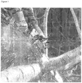
- FIG. 1 The discharge of debris such as saw dust during the operation of a traditional chainsaw is shown in Figure 1 .
- the generated debris such as saw dusts or wood chips will propel in generally all directions, and particularly, upwardly and outwardly from the cutting site.
- a significant amount of the propelling saw dusts or chips will be discharged towards the operator or anything near the cutting site which will be messy and inconvenient.
- the debris may come with sharp edges or in the form of tiny splinters which may cause irritation or even injury to the operator.
- the present invention relates to a chainsaw.
- the chainsaw comprises a debris deflecting device for deflecting the generated debris from the operator during the operation of the chainsaw
- the chainsaw includes a body having a motor, such as an electric motor or a gasoline motor.
- the motor is capable of actuating an operation member, which may include a drive shaft for driving the movement of a saw blade to perform the operation of the chainsaw.
- the body further comprises a debris deflector arranged to deflect debris generated during the operation of the chainsaw.
- Figures 2A and 2B show a first embodiment of the present invention.
- the chainsaw 100 includes a debris deflector 104 movable between a deflecting position 120 in which the debris deflector 104 is extended from the body 102, and a non-deflecting position 122 in which the debris deflector 104 is retracted into the body 102.
- the debris deflector 104 comprises an elongated body 110 with a planar deflecting surface 118 as shown in the figures.
- the debris deflector can be of other possible configurations such as a bending body with a curved deflecting surface, as long as a person skilled in the art would consider suitable in performing the debris deflecting function.
- the elongated body 110 includes a portion 124 that is in a length that extends out from the body 102 which is long enough to deflect the debris generated during operation of the chainsaw 100.
- the length of the potion 124 of the debris deflector 104 that extends out is 25 mm, alternatively, the length of the portion 124 that extends out may be longer than 25 mm for a better debris deflecting performance, or shorter than 25 mm in some other designs such as a simpler debris deflector structure.
- the debris deflector 104 is arranged to deflect the saw dust generated in a controlled manner by blocking some of the paths that the saw dust may propel.
- the debris will then be forced to propel in certain direction, for example, the debris deflector may force the debris to propel only along the cutting direction but not towards the operator. Examples of operation will be described below in more details in the later part of this disclosure.
- the body 102 comprises an actuating means 112 operable to move the debris deflector 104 between the deflecting position 120 and the non-deflecting position 122.
- the actuating means comprises a rotatable knob 112 operable for extending or retracting the elongated body 110 of the debris deflector 104, the rotatable knob 112 connects with a gear member 114 adapted to engage a plurality of notches 116 at the debris deflector 120.
- the user may rotate the knob 112 in a direction, such that the gear 114 rotates accordingly and move the elongated body 110 of the debris deflector 120 to the deflecting position 120, which is extending out from the body 102 as shown in Figure 2A and Figure 2B .
- the user may rotate the knob 112 in a reversed direction, such that the gear 114 rotates accordingly in a reversed direction and move the elongated body 110 of the debris deflector 104 to the non-deflecting position 122.
- accidental damage to the debris deflector 104 may be avoided by retracting and protecting the debris deflector 104 in the body 102 when the chainsaw 100 is stored or moved.
- the body 202 comprises an actuating means operable to move the debris deflector 204 between the deflecting position 220 and the non-deflecting position 222.
- the actuating means comprises a press button 212 operable for extending the debris deflector 204, the debris deflector 204 is retractable manually by applying a pressure on the debris deflector 204 towards the body 202.
- the debris deflector 204 comprises an elongated body 210.
- the elongated body 210 includes a portion 224 that is in a length that extends out from the body 202 which is long enough to deflect the debris generated during operation of the chainsaw 200.
- the user may press the button 212 on the body 202, such that the elongated body 210 of the debris deflector 204 move to the deflecting position 220, which is extending out from the body 202 as shown in Figure 3A and Figure 3B .
- the user may apply a pressure on the elongated body 210 of the debris deflector 204 towards the body 202 and move the debris deflector 204 to the non-deflecting position 222.
- the body 202 may include a first locking means 214 adapted to lock the debris deflector 204 at the deflecting position 220 and the non-deflecting position 222.
- the first locking means 214 comprises a resilient member 216, which is arrange to assist the release and locking of the debris deflector 204.
- the resilient member 216 may be compressed when the debris deflector 204 is locked in the non-deflecting position 222, whereupon a user press the button 212 on the body 202, the locking means 214 is released and the resilient member 216 is arrange to push the debris deflector 214 out of the body 202.
- the debris deflector 104 or 204 is elongated with a planar deflecting surface, as shown in Figures 2A, 2B , 3A and 3B .
- the debris deflector is in any other shapes or surfaces such as ruffle surface or bending surface which is operable to perform the debris deflection function.
- the debris deflector is arranged to direct an air flow generated by the motor to deflect the debris and thus in these embodiments the debris deflector may not necessarily need to make physical contact with the debris, but can, for example, direct air flow to blow away the debris.
- the air flow is an exhaust gas discharged from the motor.
- the air flow is generated by a fan or discharged from a pipe connected to the source of air flow generated by the motor.
- the air flow may be used for cooling the components of the chain saw, especially the motor and the control circuits in the body, the exhaust gas may then be used for blowing the saw dust in certain direction.
- the debris deflector is adapted to deflect the air flow in a direction substantially away from an operator of the power tool.
- the debris deflector is adapted to deflect the air flow in a direction substantially transverse to a direction of movement of the operation member.
- the direction of the air flow can be adjusted to any desirable direction which favors the operation of the power tool.
- the debris deflector is movable between the deflecting position and the non-deflecting position such that the debris deflector is not deflecting the debris generated during operation.
- a further, additional debris deflector 304 is pivotedly connected with the body 302, and the debris deflector 304 comprises a door 312 movable between an air directing position 320 in which the air flow is deflected, and an air non-directing position 322 in which the air flow is not deflected, and the door 312 is pivotedly movable between the air directing position 320 and the air non-directing position 322.
- the user may position the door 312 in an air directing position 320 shown in Figure 4A , such that the debris deflector 304 is arranged to redirect the air generated from the motor, and the redirected air is arrange to direct the debris to a desire direction, which is usually away from the operator of the chainsaw 300 or transverse to a direction of movement of the operation member of the chainsaw 300.
- the user may position the door 312 in an air non-directing position 322 shown in Figure 4B , and the air flow generated will be discharged without being redirected, and the debris will not be deflected by the debris deflector 304.
- the operator of the chainsaw may decide to operate the chainsaw with or without the debris deflecting function. For example, in some occasion, when another worker is working adjacent to the operator of the chainsaw, debris deflected to the worker may be dangerous. In that case, the operator of the chainsaw may choose to disable the debris deflecting function.
- the further, additional debris deflector comprises a door 412 movable between an air directing position 420 in which the air flow is deflected, and an air non-directing position 422 in which the air flow is not deflected, and the door 412 comprises a sliding plate 414 slidably movable between the air directing position 420 and the air non-directing position 422.
- the user may position the sliding plate 414 in an air directing position, such that the door 412 open and the air vents 416 close respectively and the debris deflector 404 is arranged to redirect the air generated from the motor, and the redirected air is arranged to direct the debris to a desire direction, which is usually away from the operator of the chainsaw 400 or transverse to a direction of movement of the operation member of the chainsaw 400.
- the user may position the sliding plate 414 in an air non-directing position 420 shown in Figure 5B , such that the door 412 close and the air vents 416 open respectively, and the exhaust air is only discharged from the open air vents 416 and is not redirected by the debris deflector 404, thus the debris are not deflected by the debris deflector 404
- the debris deflector 404 may comprise a second locking means 430 adapted to lock the door at the air directing position 420 and the air non-directing position 422.
- the second locking means 430 may comprise a resilient member 432.
- the second locking means 430 comprises a latch mechanism 434.
- the further, additional debris deflector 504 comprises a door 512, which is movable between an air directing position 520 in which the air flow is deflected, and an air non-directing position 522 in which the air flow is not deflected, and the door 512 is movable from the air non-directing position 522 to the air directing position 520 by means of gravitation force as shown in Figure 6B .
- the door 512 is movable from the air non-directing position to the air directing position by the air flow generated by the motor.
- the door 512 will extend from the body 502 by means of motor discharge wind force, and deflect the wind towards the predetermined direction to blow debris away.
- the door 512 may be retracted automatically while the chainsaw 500 is placed on the ground.
- the door 512 may be removed form chainsaw 500 if the air deflecting function is not needed.
- the door 512 When a user operates the chainsaw 500 with the air vents 514 on the body 502 which discharge the air flow generated by the motor, the door 512 positioned in an air directing position 520 by gravitation force or the force of the air flow generated by the motor, such that the debris deflector 504 is arranged to redirect the air generated from the motor and discharged from a air vents 514 on the body 502, and the redirected air is arrange to direct the debris to a desire direction, which is usually away from the operator of the chainsaw 500 or transverse to a direction of movement of the operation member of the chainsaw 500.
- the debris deflector is removable from the body of the chainsaw, or may be installed on the chain saw on demand.
- the motor of the chainsaw is powered by electricity, alternatively, the motor is powered by gasoline.
- the motor is an AC motor, alternatively, the motor is a DC motor.
- the chainsaw may include one or more debris deflectors in accordance with the embodiments of the present invention.
- the debris deflector in accordance with the first two embodiments enables the operator of a chainsaw to perform cutting operation without discharging the saw dust towards the operator when the operator is holding the chainsaw at a position in front of the operator.
- additional debris deflectors in accordance with the last three embodiments further discharge the saw dust away from the operator in a direction transverse to the cutting direction.
- the debris deflector effectively protects the operator of a chain saw from injured by the debris discharged during operation.
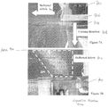
- FIG. 7A there is shown the deflection path of debris 702 during the operation of a chainsaw 700 of the present invention when viewed from the front of the chainsaw 700.
- the operator 704 of the chain saw 700 cut a piece of wood 706 in a downward direction 708.
- the debris 702 is deflected towards the left and hence the operator 704 standing on the right is free from debris 702 generated during the cutting operation.
- the deflected debris 702 are mostly discharged to an area 710 from the top to the top left portion of the image, and the operator 704 of the chainsaw 700 is positioned at the bottom right corner which shows that the operator 704 is free from the debris 702 generated.
- the debris deflector can be arranged for deflecting debris other than chips or saw dust.
- a chainsaw may comprise more than one debris deflector, or a combination of debris deflectors :
Landscapes
- Life Sciences & Earth Sciences (AREA)
- Engineering & Computer Science (AREA)
- Mechanical Engineering (AREA)
- Wood Science & Technology (AREA)
- Forests & Forestry (AREA)
- Processing Of Stones Or Stones Resemblance Materials (AREA)
Description
- The present invention relates to a chainsaw as per the preamble of claim 1.
- Conventional chainsaws have been commonly used for cutting a work piece or trees. When the blade engages the subject to be cut during the cutting action, debris such as saw dusts or wood chips will propel upwardly and outwardly from the cutting site. This is particularly undesirable for chainsaws of which the operator would be handling the tool at a closer distance from the cutting site during the operation, and therefore a significant amount of the propelling saw dusts or chips is likely to reach the operator.
US3380493 discloses a chainsaw as per the preamble of claim 1. - In accordance with the present invention there is provided a chainsaw comprising the combination of features of claim 1.
- Preferred embodiments of the invention are defined by the dependent claims.
- In one preferred embodiment, the body comprises an actuating means operable to move the debris deflector between the deflecting position and the non-deflecting position.
- In one preferred embodiment, the body comprises a first locking means adapted to lock the debris deflector at the deflecting position and the non-deflecting position.
- In one preferred embodiment, the actuating means comprises a rotatable knob operable for extending and retracting the debris deflector.
- In one preferred embodiment, the rotatable knob connects with a gear member adapted to engage a plurality of notches at the debris deflector.
- In one preferred embodiment, the actuating means comprises a press button operable for extending the debris deflector.
- In one preferred embodiment, the debris deflector is retractable manually by applying a pressure on the debris deflector towards the body.
- In one preferred embodiment, the first locking means comprises a resilient member.
- In one preferred embodiment, the debris deflector is elongated with a planar deflecting surface.
- In one preferred embodiment, a further debris deflector is arranged to direct an air flow generated by the motor to deflect the debris.
- In one preferred embodiment, the further debris deflector is pivotedly connected with the body.
- In one preferred embodiment, the further debris deflector comprises a door movable between an air directing position in which the air flow is deflected, and an air non-directing position in which the air flow is not deflected.
- In one preferred embodiment, the door is pivotedly movable between the air directing position and the air non-directing position.
- In one preferred embodiment, the door comprises a sliding plate slidably movable between the air directing position and the air non-directing position.
- In one preferred embodiment, the further debris deflector comprises a second locking means adapted to lock the door at the air directing position and the air non-directing position.
- In one preferred embodiment, the second locking means comprises a resilient member.
- In one preferred embodiment, the second locking means comprises a latch mechanism.
- In preferred embodiment, the door is movable from the air non-directing position to the air directing position by means of gravitation force.
- In one preferred embodiment, the door is movable from the air non-directing position to the air directing position by the air flow generated by the motor.
- In one preferred embodiment, the air flow is an exhaust gas discharged from the motor.
- In one preferred embodiment, the debris deflector is adapted to deflect the air flow in a direction substantially away from an operator of the power tool.
- In one preferred embodiment, the debris deflector is adapted to deflect the air flow in a direction substantially transverse to a direction of movement of the operation member.
- In one preferred embodiment, the motor is powered by electricity or gasoline.
- In one preferred embodiment, the motor is an AC motor or a DC motor.
- Embodiments of the present invention will now be described, by way of example, with reference to the accompanying drawings in which:
-
Figure 1 is a photographic image showing the discharge of saw dust during the operation of a chainsaw in the prior art; -
Figure 2A is a perspective view of a debris deflecting device for a chainsaw in accordance with a first embodiment of the present invention; -
Figure 2B is another perspective view of the debris deflecting device of the first embodiment as shown inFigure 2A ; -
Figure 3A is a perspective view of a debris deflecting device for a power tool in accordance with a second embodiment of the present invention; -
Figure 3B is another perspective view of the debris deflecting device of the second embodiment as shown inFigure 3A ; -
Figure 4A is a perspective view of a further, additional debris deflecting device for a chainsaw in accordance with a third embodiment of the present invention; -
Figure 4B is another perspective view of the debris deflecting device as shown inFigure 4A ; -
Figure 5A is a perspective view of a further, additional debris deflecting device for a chainsaw in accordance with a fourth embodiment of the present invention; -
Figure 5B is another perspective view of the debris deflecting device as shown inFigure 5A ; -
Figure 6A is a perspective view of a further, additional debris deflecting device for a chainsaw in accordance with a fifth embodiment of the present invention; and -
Figure 6B is another perspective view of the debris deflecting device as shown inFigure 6A . -
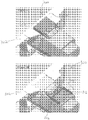
Figure 7A is a photographic image showing the deflection path of debris during the operation of a chainsaw of the present invention when viewed from the front of the chainsaw -
Figure 7B is a photographic image showing the deflection path of debris during the operation of the chainsaw ofFigure 7A when viewed from the top of the chainsaw - The discharge of debris such as saw dust during the operation of a traditional chainsaw is shown in
Figure 1 . When the moving blade of a chainsaw engages an object to be cut, such as a piece of wood log or a tree trunk, , the generated debris such as saw dusts or wood chips will propel in generally all directions, and particularly, upwardly and outwardly from the cutting site. A significant amount of the propelling saw dusts or chips will be discharged towards the operator or anything near the cutting site which will be messy and inconvenient. In some circumstances, the debris may come with sharp edges or in the form of tiny splinters which may cause irritation or even injury to the operator. - The present invention relates to a chainsaw. The chainsaw comprises a debris deflecting device for deflecting the generated debris from the operator during the operation of the chainsaw The chainsaw includes a body having a motor, such as an electric motor or a gasoline motor. The motor is capable of actuating an operation member, which may include a drive shaft for driving the movement of a saw blade to perform the operation of the chainsaw. The body further comprises a debris deflector arranged to deflect debris generated during the operation of the chainsaw.
-
Figures 2A and 2B show a first embodiment of the present invention. As shown in the figures, thechainsaw 100 includes adebris deflector 104 movable between a deflecting position 120 in which thedebris deflector 104 is extended from thebody 102, and a non-deflecting position 122 in which thedebris deflector 104 is retracted into thebody 102. - Preferably, the
debris deflector 104 comprises an elongated body 110 with a planardeflecting surface 118 as shown in the figures. Alternatively, the debris deflector can be of other possible configurations such as a bending body with a curved deflecting surface, as long as a person skilled in the art would consider suitable in performing the debris deflecting function. - Preferably, the elongated body 110 includes a portion 124 that is in a length that extends out from the
body 102 which is long enough to deflect the debris generated during operation of thechainsaw 100. Preferably, the length of the potion 124 of thedebris deflector 104 that extends out is 25 mm, alternatively, the length of the portion 124 that extends out may be longer than 25 mm for a better debris deflecting performance, or shorter than 25 mm in some other designs such as a simpler debris deflector structure. - In this embodiment, during the operation of the
chainsaw 100, thedebris deflector 104 is arranged to deflect the saw dust generated in a controlled manner by blocking some of the paths that the saw dust may propel. The debris will then be forced to propel in certain direction, for example, the debris deflector may force the debris to propel only along the cutting direction but not towards the operator. Examples of operation will be described below in more details in the later part of this disclosure. - Preferably, the
body 102 comprises an actuating means 112 operable to move thedebris deflector 104 between the deflecting position 120 and the non-deflecting position 122. In this embodiment, the actuating means comprises a rotatable knob 112 operable for extending or retracting the elongated body 110 of thedebris deflector 104, the rotatable knob 112 connects with agear member 114 adapted to engage a plurality ofnotches 116 at the debris deflector 120. - When a user operates the
chainsaw 100 with the debris deflecting function, the user may rotate the knob 112 in a direction, such that thegear 114 rotates accordingly and move the elongated body 110 of the debris deflector 120 to the deflecting position 120, which is extending out from thebody 102 as shown inFigure 2A and Figure 2B . When the user decides to store thechainsaw 100 or to operate thechainsaw 100 without the debris deflecting function, the user may rotate the knob 112 in a reversed direction, such that thegear 114 rotates accordingly in a reversed direction and move the elongated body 110 of thedebris deflector 104 to the non-deflecting position 122. - Advantageously, accidental damage to the
debris deflector 104 may be avoided by retracting and protecting thedebris deflector 104 in thebody 102 when thechainsaw 100 is stored or moved. - Referring to
Figure 3A and 3B , preferably, the body 202 comprises an actuating means operable to move thedebris deflector 204 between the deflecting position 220 and the non-deflecting position 222. In this embodiment, the actuating means comprises a press button 212 operable for extending thedebris deflector 204, thedebris deflector 204 is retractable manually by applying a pressure on thedebris deflector 204 towards the body 202. - Similar to the
debris deflector 104, thedebris deflector 204 comprises an elongated body 210. The elongated body 210 includes aportion 224 that is in a length that extends out from the body 202 which is long enough to deflect the debris generated during operation of the chainsaw 200. - When a user operates the chainsaw 200 with the debris deflecting function, the user may press the button 212 on the body 202, such that the elongated body 210 of the
debris deflector 204 move to the deflecting position 220, which is extending out from the body 202 as shown inFigure 3A and Figure 3B . When the user decides to store the chainsaw 200 or to operate the chainsaw 200 without the debris deflecting function, the user may apply a pressure on the elongated body 210 of thedebris deflector 204 towards the body 202 and move thedebris deflector 204 to the non-deflecting position 222. Optionally, the body 202 may include a first locking means 214 adapted to lock thedebris deflector 204 at the deflecting position 220 and the non-deflecting position 222. Preferably, the first locking means 214 comprises aresilient member 216, which is arrange to assist the release and locking of thedebris deflector 204. For example, theresilient member 216 may be compressed when thedebris deflector 204 is locked in the non-deflecting position 222, whereupon a user press the button 212 on the body 202, the locking means 214 is released and theresilient member 216 is arrange to push thedebris deflector 214 out of the body 202. - Similar to the
debris deflector 104, accidental damage to thedebris deflector 204 may be avoided by retracting and protecting thedebris deflector 204 in the body 202 when the chainsaw 200 is stored or moved. - Preferably, the
debris deflector Figures 2A, 2B ,3A and 3B . Alternatively the debris deflector is in any other shapes or surfaces such as ruffle surface or bending surface which is operable to perform the debris deflection function. - In some other embodiments, the debris deflector is arranged to direct an air flow generated by the motor to deflect the debris and thus in these embodiments the debris deflector may not necessarily need to make physical contact with the debris, but can, for example, direct air flow to blow away the debris. Preferably, the air flow is an exhaust gas discharged from the motor. Alternatively, the air flow is generated by a fan or discharged from a pipe connected to the source of air flow generated by the motor. In some embodiments, the air flow may be used for cooling the components of the chain saw, especially the motor and the control circuits in the body, the exhaust gas may then be used for blowing the saw dust in certain direction.
- Preferably, the debris deflector is adapted to deflect the air flow in a direction substantially away from an operator of the power tool. Alternatively, the debris deflector is adapted to deflect the air flow in a direction substantially transverse to a direction of movement of the operation member. Alternatively, the direction of the air flow can be adjusted to any desirable direction which favors the operation of the power tool. Optionally, the debris deflector is movable between the deflecting position and the non-deflecting position such that the debris deflector is not deflecting the debris generated during operation.
- Referring to
Figure 4A and 4B , preferably, a further,additional debris deflector 304 is pivotedly connected with thebody 302, and thedebris deflector 304 comprises adoor 312 movable between an air directing position 320 in which the air flow is deflected, and an air non-directing position 322 in which the air flow is not deflected, and thedoor 312 is pivotedly movable between the air directing position 320 and the air non-directing position 322. - When a user operates the
chainsaw power 300 with the debris deflecting function, the user may position thedoor 312 in an air directing position 320 shown inFigure 4A , such that thedebris deflector 304 is arranged to redirect the air generated from the motor, and the redirected air is arrange to direct the debris to a desire direction, which is usually away from the operator of thechainsaw 300 or transverse to a direction of movement of the operation member of thechainsaw 300. When the user decides to operate thechainsaw 300 without the debris deflecting function, the user may position thedoor 312 in an air non-directing position 322 shown inFigure 4B , and the air flow generated will be discharged without being redirected, and the debris will not be deflected by thedebris deflector 304. - Advantageously, the operator of the chainsaw may decide to operate the chainsaw with or without the debris deflecting function. For example, in some occasion, when another worker is working adjacent to the operator of the chainsaw, debris deflected to the worker may be dangerous. In that case, the operator of the chainsaw may choose to disable the debris deflecting function.
- Referring to
Figure 5A and 5B , preferably, the further, additional debris deflector comprises adoor 412 movable between an air directing position 420 in which the air flow is deflected, and an air non-directing position 422 in which the air flow is not deflected, and thedoor 412 comprises a slidingplate 414 slidably movable between the air directing position 420 and the air non-directing position 422. - When a user operates the
chainsaw 400 with the debris deflecting function, the user may position the slidingplate 414 in an air directing position, such that thedoor 412 open and theair vents 416 close respectively and the debris deflector 404 is arranged to redirect the air generated from the motor, and the redirected air is arranged to direct the debris to a desire direction, which is usually away from the operator of thechainsaw 400 or transverse to a direction of movement of the operation member of thechainsaw 400. When the user decides to operate thechainsaw 400 without the debris deflecting function, the user may position the slidingplate 414 in an air non-directing position 420 shown inFigure 5B , such that thedoor 412 close and theair vents 416 open respectively, and the exhaust air is only discharged from theopen air vents 416 and is not redirected by the debris deflector 404, thus the debris are not deflected by the debris deflector 404 - Optionally, the debris deflector 404 may comprise a second locking means 430 adapted to lock the door at the air directing position 420 and the air non-directing position 422. Preferably, the second locking means 430 may comprise a resilient member 432. Alternatively or additionally, the second locking means 430 comprises a
latch mechanism 434. - In yet another embodiment, with reference to
Figure 6A and 6B , the further, additional debris deflector 504 comprises adoor 512, which is movable between anair directing position 520 in which the air flow is deflected, and an air non-directing position 522 in which the air flow is not deflected, and thedoor 512 is movable from the air non-directing position 522 to theair directing position 520 by means of gravitation force as shown inFigure 6B . - Alternatively, the
door 512 is movable from the air non-directing position to the air directing position by the air flow generated by the motor. Thedoor 512 will extend from the body 502 by means of motor discharge wind force, and deflect the wind towards the predetermined direction to blow debris away. Thedoor 512 may be retracted automatically while thechainsaw 500 is placed on the ground. Optionally, thedoor 512 may be removedform chainsaw 500 if the air deflecting function is not needed. - When a user operates the
chainsaw 500 with the air vents 514 on the body 502 which discharge the air flow generated by the motor, thedoor 512 positioned in anair directing position 520 by gravitation force or the force of the air flow generated by the motor, such that the debris deflector 504 is arranged to redirect the air generated from the motor and discharged from a air vents 514 on the body 502, and the redirected air is arrange to direct the debris to a desire direction, which is usually away from the operator of thechainsaw 500 or transverse to a direction of movement of the operation member of thechainsaw 500. - In some embodiments, the debris deflector is removable from the body of the chainsaw, or may be installed on the chain saw on demand.
- Preferably, the motor of the chainsaw is powered by electricity, alternatively, the motor is powered by gasoline. Preferably, the motor is an AC motor, alternatively, the motor is a DC motor.
- The chainsaw may include one or more debris deflectors in accordance with the embodiments of the present invention. The debris deflector in accordance with the first two embodiments enables the operator of a chainsaw to perform cutting operation without discharging the saw dust towards the operator when the operator is holding the chainsaw at a position in front of the operator. The further, additional debris deflectors in accordance with the last three embodiments further discharge the saw dust away from the operator in a direction transverse to the cutting direction. The debris deflector effectively protects the operator of a chain saw from injured by the debris discharged during operation.
- With reference to
Figure 7A , there is shown the deflection path of debris 702 during the operation of achainsaw 700 of the present invention when viewed from the front of thechainsaw 700. In this example, theoperator 704 of the chain saw 700 cut a piece ofwood 706 in a downward direction 708. The debris 702 is deflected towards the left and hence theoperator 704 standing on the right is free from debris 702 generated during the cutting operation. As shown inFigure 7B , the deflected debris 702 are mostly discharged to an area 710 from the top to the top left portion of the image, and theoperator 704 of thechainsaw 700 is positioned at the bottom right corner which shows that theoperator 704 is free from the debris 702 generated. - In some embodiments, the debris deflector can be arranged for deflecting debris other than chips or saw dust. In some other embodiments, a chainsaw may comprise more than one debris deflector, or a combination of debris deflectors :
- It will be appreciated by persons skilled in the art that numerous variations and/or modifications may be made to the invention as shown in the specific embodiments without departing from the scope of the claims. The present embodiments are, therefore, to be considered in all respects as illustrative and not restrictive.
Claims (15)
- A chainsaw, comprising:a saw blade;a body (102; 202; 302; 402; 502; 602) having a motor arranged to drive the saw blade, the saw blade being arranged to generate debris during operation of the chainsaw; anda debris deflecting device comprising a debris deflector (104; 204) arranged to deflect debris generated by the saw blade,characterised in that the debris deflector (104; 204) is movable between a deflecting position (120; 220), in which the debris deflector (104; 204) is extended from the body (102; 202; 302; 402; 502; 602) to deflect debris generated during operation of the chainsaw, and a non-deflecting position (122; 222), in which the debris deflector (104; 204) is retracted into the body.
- The chainsaw according to claim 1, further comprising:
an actuating means operable to move the debris deflector (104; 204) between the deflecting position (120; 220) and the non-deflecting position (122; 222). - The chainsaw according to claim 2, wherein the actuating means comprises a rotatable knob (112) operable for extending and retracting the debris deflector (104).
- The chainsaw according to claim 3, further comprising a gear member (114) connected with the rotatable knob (112), wherein the debris deflector includes a plurality of notches (116), and wherein the gear member (114) is adapted to engage the plurality of notches (116).
- The chainsaw according to claim 2, wherein the actuating means comprises a press button (212) operable for extending the debris deflector (204).
- The chainsaw according to claim 5, wherein the debris deflector (204) is retractable manually by a user applying a pressure on the debris deflector (204) towards the body (202).
- The chainsaw according to claim 5 or 6, further comprising:
a locking means (214) adapted to lock the debris deflector (204) at the deflecting position (220) and the non-deflecting position (222). - The chainsaw according to claim 7, wherein the locking means (214) adapted to lock the debris deflector comprises a resilient member (216).
- The chainsaw according to claim 8, wherein the resilient member (216) is arranged to be compressed when the debris deflector is locked in the non-deflecting position (222), and the resilient member (216) is arranged to move the debris deflector (204) into the deflecting position when the press button (212) is actuated.
- The chainsaw according to any one of claims 1 to 9, wherein the debris deflector (104; 204) is elongated with a planar deflecting surface.
- The chainsaw according to any one of claims 1 to 10, further comprising a further debris deflector (304; 404; 504) arranged to direct an air flow generated by the motor so as to deflect debris generated by the chainsaw.
- The chainsaw according to claim 11, wherein the further debris deflector (304; 404; 504) comprises a door (312; 412; 512) movable between an air directing position (320; 420; 520) in which the air flow is deflected, and an air non-directing position (322; 422; 522) in which the air flow is not deflected.
- The chainsaw according to claim 12, wherein the door (312) is pivotedly movable between the air directing position (320) and the air non-directing position (322).
- The chainsaw according to claim 12, wherein the door (412) comprises a sliding plate (414) slidably movable between the air directing position (420) and the air non-directing position (422),
and optionally, wherein the debris deflector (404) comprises a locking means (430) adapted to lock the door (412) at the air directing position (420) and the air non-directing position (422), the locking means adapted to lock the door (412) comprising a resilient member (432) and/or a latch mechanism (434). - The chainsaw according to claim 12, wherein the door (512) is movable from the air non-directing position (522) to the air directing position (520) by means of gravitation force or by the air flow generated by the motor.
Applications Claiming Priority (1)
| Application Number | Priority Date | Filing Date | Title |
|---|---|---|---|
| PCT/CN2014/072870 WO2015131337A1 (en) | 2014-03-04 | 2014-03-04 | A power tool with dust deflector |
Publications (3)
| Publication Number | Publication Date |
|---|---|
| EP3113898A1 EP3113898A1 (en) | 2017-01-11 |
| EP3113898A4 EP3113898A4 (en) | 2017-11-01 |
| EP3113898B1 true EP3113898B1 (en) | 2020-10-21 |
Family
ID=54054349
Family Applications (1)
| Application Number | Title | Priority Date | Filing Date |
|---|---|---|---|
| EP14885027.4A Active EP3113898B1 (en) | 2014-03-04 | 2014-03-04 | A chainsaw with dust deflector |
Country Status (3)
| Country | Link |
|---|---|
| EP (1) | EP3113898B1 (en) |
| AU (2) | AU2014385783B2 (en) |
| WO (1) | WO2015131337A1 (en) |
Families Citing this family (1)
| Publication number | Priority date | Publication date | Assignee | Title |
|---|---|---|---|---|
| EP3659763B1 (en) | 2018-11-28 | 2023-05-31 | Black & Decker Inc. | Power tool |
Family Cites Families (10)
| Publication number | Priority date | Publication date | Assignee | Title |
|---|---|---|---|---|
| US3380493A (en) * | 1966-07-06 | 1968-04-30 | Joseph H. Giroux | Safety guard for chain saw |
| US4875398A (en) * | 1988-01-15 | 1989-10-24 | Atlantic Richfield Company | Retractable dust control hood and guard for rotary table saw |
| DE3841300C1 (en) * | 1988-12-08 | 1989-12-21 | Licentia Patent-Verwaltungs-Gmbh, 6000 Frankfurt, De | Component for covering the space surrounding the saw blade of a jigsaw |
| TW540463U (en) * | 2002-06-21 | 2003-07-01 | Pei-Lie Jiang | Band saw machine with protecting cover apparatus |
| CN2608245Y (en) * | 2003-05-07 | 2004-03-31 | 易图伟 | Disk saw safety protective casing |
| DE602005010468D1 (en) * | 2004-07-16 | 2008-11-27 | Makita Corp | Saw with dust collector |
| TW200706324A (en) * | 2005-08-05 | 2007-02-16 | Yang Wen Jeng | Power tool in multipurpose |
| CN202070822U (en) * | 2011-04-28 | 2011-12-14 | 赵西敬 | Modified middle saw |
| CN202377613U (en) * | 2011-12-22 | 2012-08-15 | 于波涛 | Electric safety saw blade |
| CN203254229U (en) * | 2013-04-28 | 2013-10-30 | 中建七局建筑装饰工程有限公司 | Cutting splashing protective cover |
-
2014
- 2014-03-04 AU AU2014385783A patent/AU2014385783B2/en active Active
- 2014-03-04 WO PCT/CN2014/072870 patent/WO2015131337A1/en not_active Ceased
- 2014-03-04 EP EP14885027.4A patent/EP3113898B1/en active Active
-
2019
- 2019-11-21 AU AU2019101430A patent/AU2019101430A4/en not_active Expired
Non-Patent Citations (1)
| Title |
|---|
| None * |
Also Published As
| Publication number | Publication date |
|---|---|
| EP3113898A1 (en) | 2017-01-11 |
| AU2014385783B2 (en) | 2019-08-29 |
| AU2019101430A4 (en) | 2020-01-02 |
| AU2014385783A1 (en) | 2016-08-04 |
| EP3113898A4 (en) | 2017-11-01 |
| WO2015131337A1 (en) | 2015-09-11 |
Similar Documents
| Publication | Publication Date | Title |
|---|---|---|
| US20110162501A1 (en) | Dust extraction blade guard system for power saws | |
| US5287779A (en) | Radial saw safety guards and barriers | |
| US8371034B2 (en) | Dust collection cover attachable to cutter | |
| EP2603364B1 (en) | Fence system for a power saw | |
| EP3135429B1 (en) | Dust extractor | |
| US11478865B2 (en) | Cutting device with integrated and interruptible auxiliary power supply | |
| CN100446936C (en) | Handheld Power Tools | |
| US20230060879A1 (en) | Power tool and one-hand saw | |
| JPS6345921B2 (en) | ||
| EP3140082B1 (en) | Throttle lockout with dissimilar action | |
| US20090158904A1 (en) | Dust collector for a miter saw | |
| US7989718B1 (en) | Power control engagement device for a power tool | |
| EP2123385B1 (en) | Air Deflector Assemblies for Miter Saws | |
| AU2019101430A4 (en) | A power tool with dust deflector | |
| WO2011104538A1 (en) | Guard means for a saw and method of use thereof | |
| US20120073141A1 (en) | Hand-held electric power tool with a suction adapter | |
| JP7814948B2 (en) | electric work equipment | |
| CN100486784C (en) | Electric circular saw | |
| CN201493556U (en) | Hand-held circular saw guard shield safe locking mechanism | |
| JP5333836B2 (en) | Electric tools and power tools | |
| CN201493555U (en) | Hand-held circular saw guard shield mechanism | |
| US9421625B2 (en) | Reciprocating saw with adjustable shoe | |
| JP2022095409A (en) | Cutting machine | |
| CN203994090U (en) | Power Tools with Debris Deflectors | |
| US1270430A (en) | Tool-guard. |
Legal Events
| Date | Code | Title | Description |
|---|---|---|---|
| PUAI | Public reference made under article 153(3) epc to a published international application that has entered the european phase |
Free format text: ORIGINAL CODE: 0009012 |
|
| STAA | Information on the status of an ep patent application or granted ep patent |
Free format text: STATUS: REQUEST FOR EXAMINATION WAS MADE |
|
| 17P | Request for examination filed |
Effective date: 20160729 |
|
| AK | Designated contracting states |
Kind code of ref document: A1 Designated state(s): AL AT BE BG CH CY CZ DE DK EE ES FI FR GB GR HR HU IE IS IT LI LT LU LV MC MK MT NL NO PL PT RO RS SE SI SK SM TR |
|
| AX | Request for extension of the european patent |
Extension state: BA ME |
|
| DAX | Request for extension of the european patent (deleted) | ||
| A4 | Supplementary search report drawn up and despatched |
Effective date: 20170928 |
|
| RIC1 | Information provided on ipc code assigned before grant |
Ipc: B23D 59/00 20060101AFI20170922BHEP Ipc: B27G 19/00 20060101ALI20170922BHEP |
|
| STAA | Information on the status of an ep patent application or granted ep patent |
Free format text: STATUS: EXAMINATION IS IN PROGRESS |
|
| 17Q | First examination report despatched |
Effective date: 20191105 |
|
| GRAP | Despatch of communication of intention to grant a patent |
Free format text: ORIGINAL CODE: EPIDOSNIGR1 |
|
| STAA | Information on the status of an ep patent application or granted ep patent |
Free format text: STATUS: GRANT OF PATENT IS INTENDED |
|
| INTG | Intention to grant announced |
Effective date: 20200604 |
|
| GRAS | Grant fee paid |
Free format text: ORIGINAL CODE: EPIDOSNIGR3 |
|
| GRAA | (expected) grant |
Free format text: ORIGINAL CODE: 0009210 |
|
| STAA | Information on the status of an ep patent application or granted ep patent |
Free format text: STATUS: THE PATENT HAS BEEN GRANTED |
|
| AK | Designated contracting states |
Kind code of ref document: B1 Designated state(s): AL AT BE BG CH CY CZ DE DK EE ES FI FR GB GR HR HU IE IS IT LI LT LU LV MC MK MT NL NO PL PT RO RS SE SI SK SM TR |
|
| REG | Reference to a national code |
Ref country code: GB Ref legal event code: FG4D |
|
| REG | Reference to a national code |
Ref country code: CH Ref legal event code: EP |
|
| REG | Reference to a national code |
Ref country code: DE Ref legal event code: R096 Ref document number: 602014071569 Country of ref document: DE |
|
| REG | Reference to a national code |
Ref country code: IE Ref legal event code: FG4D |
|
| REG | Reference to a national code |
Ref country code: AT Ref legal event code: REF Ref document number: 1325333 Country of ref document: AT Kind code of ref document: T Effective date: 20201115 |
|
| REG | Reference to a national code |
Ref country code: AT Ref legal event code: MK05 Ref document number: 1325333 Country of ref document: AT Kind code of ref document: T Effective date: 20201021 |
|
| REG | Reference to a national code |
Ref country code: NL Ref legal event code: MP Effective date: 20201021 |
|
| PG25 | Lapsed in a contracting state [announced via postgrant information from national office to epo] |
Ref country code: GR Free format text: LAPSE BECAUSE OF FAILURE TO SUBMIT A TRANSLATION OF THE DESCRIPTION OR TO PAY THE FEE WITHIN THE PRESCRIBED TIME-LIMIT Effective date: 20210122 Ref country code: NL Free format text: LAPSE BECAUSE OF FAILURE TO SUBMIT A TRANSLATION OF THE DESCRIPTION OR TO PAY THE FEE WITHIN THE PRESCRIBED TIME-LIMIT Effective date: 20201021 Ref country code: PT Free format text: LAPSE BECAUSE OF FAILURE TO SUBMIT A TRANSLATION OF THE DESCRIPTION OR TO PAY THE FEE WITHIN THE PRESCRIBED TIME-LIMIT Effective date: 20210222 Ref country code: NO Free format text: LAPSE BECAUSE OF FAILURE TO SUBMIT A TRANSLATION OF THE DESCRIPTION OR TO PAY THE FEE WITHIN THE PRESCRIBED TIME-LIMIT Effective date: 20210121 Ref country code: RS Free format text: LAPSE BECAUSE OF FAILURE TO SUBMIT A TRANSLATION OF THE DESCRIPTION OR TO PAY THE FEE WITHIN THE PRESCRIBED TIME-LIMIT Effective date: 20201021 Ref country code: FI Free format text: LAPSE BECAUSE OF FAILURE TO SUBMIT A TRANSLATION OF THE DESCRIPTION OR TO PAY THE FEE WITHIN THE PRESCRIBED TIME-LIMIT Effective date: 20201021 |
|
| REG | Reference to a national code |
Ref country code: LT Ref legal event code: MG4D |
|
| PG25 | Lapsed in a contracting state [announced via postgrant information from national office to epo] |
Ref country code: PL Free format text: LAPSE BECAUSE OF FAILURE TO SUBMIT A TRANSLATION OF THE DESCRIPTION OR TO PAY THE FEE WITHIN THE PRESCRIBED TIME-LIMIT Effective date: 20201021 Ref country code: SE Free format text: LAPSE BECAUSE OF FAILURE TO SUBMIT A TRANSLATION OF THE DESCRIPTION OR TO PAY THE FEE WITHIN THE PRESCRIBED TIME-LIMIT Effective date: 20201021 Ref country code: LV Free format text: LAPSE BECAUSE OF FAILURE TO SUBMIT A TRANSLATION OF THE DESCRIPTION OR TO PAY THE FEE WITHIN THE PRESCRIBED TIME-LIMIT Effective date: 20201021 Ref country code: IS Free format text: LAPSE BECAUSE OF FAILURE TO SUBMIT A TRANSLATION OF THE DESCRIPTION OR TO PAY THE FEE WITHIN THE PRESCRIBED TIME-LIMIT Effective date: 20210221 Ref country code: AT Free format text: LAPSE BECAUSE OF FAILURE TO SUBMIT A TRANSLATION OF THE DESCRIPTION OR TO PAY THE FEE WITHIN THE PRESCRIBED TIME-LIMIT Effective date: 20201021 Ref country code: ES Free format text: LAPSE BECAUSE OF FAILURE TO SUBMIT A TRANSLATION OF THE DESCRIPTION OR TO PAY THE FEE WITHIN THE PRESCRIBED TIME-LIMIT Effective date: 20201021 Ref country code: BG Free format text: LAPSE BECAUSE OF FAILURE TO SUBMIT A TRANSLATION OF THE DESCRIPTION OR TO PAY THE FEE WITHIN THE PRESCRIBED TIME-LIMIT Effective date: 20210121 |
|
| PG25 | Lapsed in a contracting state [announced via postgrant information from national office to epo] |
Ref country code: HR Free format text: LAPSE BECAUSE OF FAILURE TO SUBMIT A TRANSLATION OF THE DESCRIPTION OR TO PAY THE FEE WITHIN THE PRESCRIBED TIME-LIMIT Effective date: 20201021 |
|
| REG | Reference to a national code |
Ref country code: DE Ref legal event code: R097 Ref document number: 602014071569 Country of ref document: DE |
|
| PG25 | Lapsed in a contracting state [announced via postgrant information from national office to epo] |
Ref country code: LT Free format text: LAPSE BECAUSE OF FAILURE TO SUBMIT A TRANSLATION OF THE DESCRIPTION OR TO PAY THE FEE WITHIN THE PRESCRIBED TIME-LIMIT Effective date: 20201021 Ref country code: SK Free format text: LAPSE BECAUSE OF FAILURE TO SUBMIT A TRANSLATION OF THE DESCRIPTION OR TO PAY THE FEE WITHIN THE PRESCRIBED TIME-LIMIT Effective date: 20201021 Ref country code: RO Free format text: LAPSE BECAUSE OF FAILURE TO SUBMIT A TRANSLATION OF THE DESCRIPTION OR TO PAY THE FEE WITHIN THE PRESCRIBED TIME-LIMIT Effective date: 20201021 Ref country code: SM Free format text: LAPSE BECAUSE OF FAILURE TO SUBMIT A TRANSLATION OF THE DESCRIPTION OR TO PAY THE FEE WITHIN THE PRESCRIBED TIME-LIMIT Effective date: 20201021 Ref country code: CZ Free format text: LAPSE BECAUSE OF FAILURE TO SUBMIT A TRANSLATION OF THE DESCRIPTION OR TO PAY THE FEE WITHIN THE PRESCRIBED TIME-LIMIT Effective date: 20201021 Ref country code: EE Free format text: LAPSE BECAUSE OF FAILURE TO SUBMIT A TRANSLATION OF THE DESCRIPTION OR TO PAY THE FEE WITHIN THE PRESCRIBED TIME-LIMIT Effective date: 20201021 |
|
| PLBE | No opposition filed within time limit |
Free format text: ORIGINAL CODE: 0009261 |
|
| STAA | Information on the status of an ep patent application or granted ep patent |
Free format text: STATUS: NO OPPOSITION FILED WITHIN TIME LIMIT |
|
| PG25 | Lapsed in a contracting state [announced via postgrant information from national office to epo] |
Ref country code: DK Free format text: LAPSE BECAUSE OF FAILURE TO SUBMIT A TRANSLATION OF THE DESCRIPTION OR TO PAY THE FEE WITHIN THE PRESCRIBED TIME-LIMIT Effective date: 20201021 |
|
| 26N | No opposition filed |
Effective date: 20210722 |
|
| PG25 | Lapsed in a contracting state [announced via postgrant information from national office to epo] |
Ref country code: AL Free format text: LAPSE BECAUSE OF FAILURE TO SUBMIT A TRANSLATION OF THE DESCRIPTION OR TO PAY THE FEE WITHIN THE PRESCRIBED TIME-LIMIT Effective date: 20201021 Ref country code: MC Free format text: LAPSE BECAUSE OF FAILURE TO SUBMIT A TRANSLATION OF THE DESCRIPTION OR TO PAY THE FEE WITHIN THE PRESCRIBED TIME-LIMIT Effective date: 20201021 Ref country code: IT Free format text: LAPSE BECAUSE OF FAILURE TO SUBMIT A TRANSLATION OF THE DESCRIPTION OR TO PAY THE FEE WITHIN THE PRESCRIBED TIME-LIMIT Effective date: 20201021 |
|
| REG | Reference to a national code |
Ref country code: CH Ref legal event code: PL |
|
| PG25 | Lapsed in a contracting state [announced via postgrant information from national office to epo] |
Ref country code: SI Free format text: LAPSE BECAUSE OF FAILURE TO SUBMIT A TRANSLATION OF THE DESCRIPTION OR TO PAY THE FEE WITHIN THE PRESCRIBED TIME-LIMIT Effective date: 20201021 |
|
| REG | Reference to a national code |
Ref country code: BE Ref legal event code: MM Effective date: 20210331 |
|
| PG25 | Lapsed in a contracting state [announced via postgrant information from national office to epo] |
Ref country code: CH Free format text: LAPSE BECAUSE OF NON-PAYMENT OF DUE FEES Effective date: 20210331 Ref country code: LU Free format text: LAPSE BECAUSE OF NON-PAYMENT OF DUE FEES Effective date: 20210304 Ref country code: LI Free format text: LAPSE BECAUSE OF NON-PAYMENT OF DUE FEES Effective date: 20210331 Ref country code: IE Free format text: LAPSE BECAUSE OF NON-PAYMENT OF DUE FEES Effective date: 20210304 |
|
| PG25 | Lapsed in a contracting state [announced via postgrant information from national office to epo] |
Ref country code: IS Free format text: LAPSE BECAUSE OF FAILURE TO SUBMIT A TRANSLATION OF THE DESCRIPTION OR TO PAY THE FEE WITHIN THE PRESCRIBED TIME-LIMIT Effective date: 20210221 |
|
| PG25 | Lapsed in a contracting state [announced via postgrant information from national office to epo] |
Ref country code: BE Free format text: LAPSE BECAUSE OF NON-PAYMENT OF DUE FEES Effective date: 20210331 |
|
| PG25 | Lapsed in a contracting state [announced via postgrant information from national office to epo] |
Ref country code: HU Free format text: LAPSE BECAUSE OF FAILURE TO SUBMIT A TRANSLATION OF THE DESCRIPTION OR TO PAY THE FEE WITHIN THE PRESCRIBED TIME-LIMIT; INVALID AB INITIO Effective date: 20140304 |
|
| PG25 | Lapsed in a contracting state [announced via postgrant information from national office to epo] |
Ref country code: CY Free format text: LAPSE BECAUSE OF FAILURE TO SUBMIT A TRANSLATION OF THE DESCRIPTION OR TO PAY THE FEE WITHIN THE PRESCRIBED TIME-LIMIT Effective date: 20201021 |
|
| PG25 | Lapsed in a contracting state [announced via postgrant information from national office to epo] |
Ref country code: MK Free format text: LAPSE BECAUSE OF FAILURE TO SUBMIT A TRANSLATION OF THE DESCRIPTION OR TO PAY THE FEE WITHIN THE PRESCRIBED TIME-LIMIT Effective date: 20201021 |
|
| PG25 | Lapsed in a contracting state [announced via postgrant information from national office to epo] |
Ref country code: MT Free format text: LAPSE BECAUSE OF FAILURE TO SUBMIT A TRANSLATION OF THE DESCRIPTION OR TO PAY THE FEE WITHIN THE PRESCRIBED TIME-LIMIT Effective date: 20201021 |
|
| PG25 | Lapsed in a contracting state [announced via postgrant information from national office to epo] |
Ref country code: TR Free format text: LAPSE BECAUSE OF FAILURE TO SUBMIT A TRANSLATION OF THE DESCRIPTION OR TO PAY THE FEE WITHIN THE PRESCRIBED TIME-LIMIT Effective date: 20201021 |
|
| PGFP | Annual fee paid to national office [announced via postgrant information from national office to epo] |
Ref country code: GB Payment date: 20260327 Year of fee payment: 13 |
|
| PGFP | Annual fee paid to national office [announced via postgrant information from national office to epo] |
Ref country code: DE Payment date: 20260327 Year of fee payment: 13 |
|
| PGFP | Annual fee paid to national office [announced via postgrant information from national office to epo] |
Ref country code: FR Payment date: 20260325 Year of fee payment: 13 |