EP3113862B1 - Method for enhanced separation of hydrogen sulfide and ammonia in a hydrogen sulfide stripper - Google Patents
Method for enhanced separation of hydrogen sulfide and ammonia in a hydrogen sulfide stripper Download PDFInfo
- Publication number
- EP3113862B1 EP3113862B1 EP15758346.9A EP15758346A EP3113862B1 EP 3113862 B1 EP3113862 B1 EP 3113862B1 EP 15758346 A EP15758346 A EP 15758346A EP 3113862 B1 EP3113862 B1 EP 3113862B1
- Authority
- EP
- European Patent Office
- Prior art keywords
- hydrogen sulfide
- stripper
- stream
- sour water
- ammonia
- Prior art date
- Legal status (The legal status is an assumption and is not a legal conclusion. Google has not performed a legal analysis and makes no representation as to the accuracy of the status listed.)
- Active
Links
Images
Classifications
-
- B—PERFORMING OPERATIONS; TRANSPORTING
- B01—PHYSICAL OR CHEMICAL PROCESSES OR APPARATUS IN GENERAL
- B01D—SEPARATION
- B01D19/00—Degasification of liquids
- B01D19/0005—Degasification of liquids with one or more auxiliary substances
- B01D19/001—Degasification of liquids with one or more auxiliary substances by bubbling steam through the liquid
- B01D19/0015—Degasification of liquids with one or more auxiliary substances by bubbling steam through the liquid in contact columns containing plates, grids or other filling elements
-
- B—PERFORMING OPERATIONS; TRANSPORTING
- B01—PHYSICAL OR CHEMICAL PROCESSES OR APPARATUS IN GENERAL
- B01D—SEPARATION
- B01D53/00—Separation of gases or vapours; Recovering vapours of volatile solvents from gases; Chemical or biological purification of waste gases, e.g. engine exhaust gases, smoke, fumes, flue gases, aerosols
- B01D53/14—Separation of gases or vapours; Recovering vapours of volatile solvents from gases; Chemical or biological purification of waste gases, e.g. engine exhaust gases, smoke, fumes, flue gases, aerosols by absorption
- B01D53/1425—Regeneration of liquid absorbents
-
- C—CHEMISTRY; METALLURGY
- C01—INORGANIC CHEMISTRY
- C01C—AMMONIA; CYANOGEN; COMPOUNDS THEREOF
- C01C1/00—Ammonia; Compounds thereof
- C01C1/02—Preparation, purification or separation of ammonia
- C01C1/12—Separation of ammonia from gases and vapours
-
- C—CHEMISTRY; METALLURGY
- C02—TREATMENT OF WATER, WASTE WATER, SEWAGE, OR SLUDGE
- C02F—TREATMENT OF WATER, WASTE WATER, SEWAGE, OR SLUDGE
- C02F1/00—Treatment of water, waste water, or sewage
- C02F1/20—Treatment of water, waste water, or sewage by degassing, i.e. liberation of dissolved gases
-
- C—CHEMISTRY; METALLURGY
- C02—TREATMENT OF WATER, WASTE WATER, SEWAGE, OR SLUDGE
- C02F—TREATMENT OF WATER, WASTE WATER, SEWAGE, OR SLUDGE
- C02F2101/00—Nature of the contaminant
- C02F2101/10—Inorganic compounds
- C02F2101/101—Sulfur compounds
-
- C—CHEMISTRY; METALLURGY
- C02—TREATMENT OF WATER, WASTE WATER, SEWAGE, OR SLUDGE
- C02F—TREATMENT OF WATER, WASTE WATER, SEWAGE, OR SLUDGE
- C02F2101/00—Nature of the contaminant
- C02F2101/10—Inorganic compounds
- C02F2101/16—Nitrogen compounds, e.g. ammonia
-
- C—CHEMISTRY; METALLURGY
- C02—TREATMENT OF WATER, WASTE WATER, SEWAGE, OR SLUDGE
- C02F—TREATMENT OF WATER, WASTE WATER, SEWAGE, OR SLUDGE
- C02F2103/00—Nature of the water, waste water, sewage or sludge to be treated
- C02F2103/34—Nature of the water, waste water, sewage or sludge to be treated from industrial activities not provided for in groups C02F2103/12 - C02F2103/32
- C02F2103/36—Nature of the water, waste water, sewage or sludge to be treated from industrial activities not provided for in groups C02F2103/12 - C02F2103/32 from the manufacture of organic compounds
- C02F2103/365—Nature of the water, waste water, sewage or sludge to be treated from industrial activities not provided for in groups C02F2103/12 - C02F2103/32 from the manufacture of organic compounds from petrochemical industry (e.g. refineries)
Definitions
- H2S stripper Conventional technology separately recovers H2S and NH3 from sour water using an H2S stripper and an NH3 stripper, which is sometimes referred to as a two-column sour water stripping process.
- This process yields acid gas (H2S) with less than 50 ppmw NH3 and a high purity gaseous or liquid NH3 product.
- the separated water is of excellent quality, making it suitable for reuse as coke drum quench water, crude unit desalter water, and hydro-processing unit injection water or it may be sent to effluent treating for discharge.
- the deoiled sour water stream 115 is sent to a feed/product exchanger 114 , which acts as a heat exchanger to heat the deoiled sour water stream 115 and cool the NH3 stripper bottoms stream 132 to produce a heated deoiled sour water stream 116 and the stripped water stream 134 .
- a feed/product exchanger 114 acts as a heat exchanger to heat the deoiled sour water stream 115 and cool the NH3 stripper bottoms stream 132 to produce a heated deoiled sour water stream 116 and the stripped water stream 134 .
- the components comprising the NH3 stripper bottoms stream 132 , stripped water stream 134 and the components comprising the deoiled sour water stream 115 , heated deoiled sour water stream 116 are, respectively, the same but may have different concentrations and temperatures.
- the heated deoiled sour water stream 116 is then sent to an H2S stripper 118 .
- the H2S stripper 118 contains trays or packing (not shown) that the heated deoiled sour water stream 116 flows through and around to separate H2S from the heated deoiled sour water stream 116 .
- a cooled reflux water stream (e.g. water wash) 136 is used remove heat and suppress evolution of gaseous NH3 in the H2S stripper.
- a reboiler 137 acts as a heat exchanger to provide the energy required to i) heat the heated deoiled sour water stream 116 and the cooled reflux water stream 136 to a preferred temperature; and ii) strip out H2S from the heated deoiled sour water stream 116 .
- the resulting H2S stripper overheads stream 120 is sent to a knock out drum 138 to substantially remove any entrained droplets and produce H2S stream 126 .
- the H2S stream 126 is of high purity and is an excellent feed for a sulfur recovery unit (SRU) or a sulfuric acid plant. It contains a negligible amount of NH3 (less than 50 ppmw) and very little hydrocarbons since the sour water feeds 102 have been degassed.
- the H2S stream 126 is available at about 6.89-12.4 barg (100-180 psig) and 37.8-48.9°C (100-120°F)
- the resulting H2S stripper bottoms stream 130 which contains NH3 and some H2S, is sent directly to the NH3 stripper 106 .
- the NH3 stripper 106 is a steam re-boiled, refluxed distillation column. In the NH3 stripper 106 , essentially all NH3 and any remaining H2S are removed from the H2S stripper bottoms stream 130 , which leaves the NH3 stripper 106 as an NH3 stripper bottoms stream 132 .
- the NH3 stripper bottoms stream 132 is sent to the feed/product exchanger 114 where heat is exchanged with the deoiled sour water stream 115 and the NH3 stripper bottoms stream 132 is cooled to form the stripped water stream 134 .
- the stripped water stream 134 is suitable for many plant reuse needs or may be discharged.
- the containment levels of H2S and NH3 in the stripped water stream 134 may be tailored to individual requirements and is typically 10-50 ppmw NH3 and 1-25 ppmw H2S.
- the stripped water stream 134 is available at about 37.8-93.3°C (100-200°F).
- NH3 stripper 106 essentially all NH3 and any remaining H2S are removed from the H2S stripper bottoms stream 130 , which leaves the NH3 stripper 106 as an NH3 stripper overheads stream 133 .
- the NH3 stripper overheads stream 133 is sent to an overhead condenser where it is converted to an NH3 vapor stream and an NH3 liquid stream.
- a knock out drum 139 separates the NH3 vapor stream 140 and the NH3 liquid stream 150 .
- a portion of the NH3 liquid stream 150 is returned as reflux to the NH3 stripper 106 and another portion of the NH3 liquid stream 150 forms the recycle stream 104 .
- a reboiler 141 acts as a heat exchanger to provide the energy required to remove NH3 and any remaining H2S.
- the NH3 vapor stream 140 is an NH3-rich gas, which may be processed in a variety of ways.
- the NH3 vapor stream 140 is sent to a water wash 142 to remove residual amounts of H2S and some hydrocarbons. This step is also referred to as water scrubbing, which produces a scrubbed NH3 vapor stream 160 . If NH3 recovery is not desired or economic, the scrubbed NH3 vapor stream 160 may be incinerated. In most cases, however, it is desirable to further purify the scrubbed NH3 vapor stream 160 to produce either anhydrous liquid NH3 170 or aqueous NH3 180 suitable for commercial use.
- the scrubbed NH3 vapor stream 160 is sent to a caustic wash 144 to remove residual contaminants including some hydrocarbons.
- This step is also referred to as caustic scrubbing, which produces a double scrubbed NH3 vapor stream 162 and may be necessary when problems are expected with process upsets, carbon dioxide, or complex sulfur compounds (e.g. mercaptans or disulfides).
- the double scrubbed NH3 vapor stream 162 may be sent to either a compressor 146 or a refrigeration unit 148 to produce the anhydrous liquid NH3 170 , which contains a negligible amount of H2S (less than 5 ppmw).
- the present invention overcomes one or more of the prior art disadvantages by providing a method for enhanced separation of H2S and NH3 in an H2S stripper using a stripping gas consisting of carbon dioxide and a gas selected from Hydrogen, Helium, Neon, Argon, Krypton, Radon, diatomic nitrogen, methane and ethane.
- a stripping gas consisting of carbon dioxide and a gas selected from Hydrogen, Helium, Neon, Argon, Krypton, Radon, diatomic nitrogen, methane and ethane.
- a system for separating hydrogen sulfide and ammonia which comprises: i) a hydrogen sulfide stripper for separating the hydrogen sulfide and the ammonia; and ii) a stripping gas stream connected to the hydrogen sulfide stripper, wherein the stripping gas stream consists of carbon dioxide and a gas selected from Hydrogen, Helium, Neon, Argon, Krypton, Radon, diatomic nitrogen, methane and ethane.
- the present invention is a method for separating hydrogen sulfide and ammonia, which comprises: i) introducing a sour water mixture of the hydrogen sulfide and the ammonia into a hydrogen sulfide stripper; ii) introducing a stripping gas into the hydrogen sulfide stripper, wherein the Stripping gas consists of carbon dioxide and a gas selected from Hydrogen, Helium, Neon, Argon, Krypton, Radon, diatomic nitrogen, methane and ethane; and iii) separating most of the hydrogen sulfide and the ammonia in the sour water mixture using the stripping gas in the hydrogen sulfide stripper, which forms a hydrogen sulfide stripper overheads stream and a hydrogen sulfide stripper bottoms stream
- the present invention provides systems and methods to enhance the separation of H2S and NH3 in an H2S stripper using carbon dioxide and a gas selected from Hydrogen, Helium, Neon, Argon, Krypton, Radon, diatomic nitrogen, methane and ethane.
- a gas selected from Hydrogen, Helium, Neon, Argon, Krypton, Radon, diatomic nitrogen, methane and ethane also referred to as a stripping gas, is to enhance the separation of H2S and NH3 during the H2S stripping stage by i) lowering the partial pressure of H2S; and ii) providing a stripping action.
- FIG. 2 a schematic diagram of the H2S stripping stage in FIG. 1A illustrates the use of a stripping gas stream 202 to enhance the separation of H2S and NH3 in the H2S stripper 118 .
- This stage can consist of various pieces of equipment depending upon the ultimate concentration and quality of NH3 desired.
- the stripping gas stream 202 may be introduced anywhere between the top and bottom of the H2S stripper 118 . Preferably, however, the stripping gas stream 202 is introduced near the bottom of the H2S stripper 118 because it will contact more of the heated deoiled sour water stream 116 . In this manner, any conventional two-column sour water stripping system that includes a H2S stripping stage may be easily retrofitted with the introduction of a stripping gas.
- the stripping gas stream 202 consists of carbon dioxide and an inert gas, which is a gas that does not react with other constituents of the H2S stripper 118 or sour water stripper, wherein the inert gas is selected from Hydrogen, Helium, Neon, Argon, Krypton, Radon, diatomic nitrogen, methane and ethane.
- the separation of the H2S and NH3 may be improved by at least five percent.
- the consumption of utilities e.g. reboiler heating media
- the two-column sour water stripping system will be lowered resulting in energy savings or performance may be improved with the same utility consumption.
Landscapes
- Chemical & Material Sciences (AREA)
- Organic Chemistry (AREA)
- Chemical Kinetics & Catalysis (AREA)
- Analytical Chemistry (AREA)
- Engineering & Computer Science (AREA)
- General Chemical & Material Sciences (AREA)
- Oil, Petroleum & Natural Gas (AREA)
- Inorganic Chemistry (AREA)
- Life Sciences & Earth Sciences (AREA)
- Hydrology & Water Resources (AREA)
- Environmental & Geological Engineering (AREA)
- Water Supply & Treatment (AREA)
- Gas Separation By Absorption (AREA)
- Physical Water Treatments (AREA)
- Hydrogen, Water And Hydrids (AREA)
- Carbon And Carbon Compounds (AREA)
- Separation Using Semi-Permeable Membranes (AREA)
- Industrial Gases (AREA)
Description
- The priority of
U.S. Provisional Patent Application No. 61/948,118 filed March 5, 2014 - Not applicable.
- The present invention generally relates to a method for enhanced separation of hydrogen sulfide (H2S) and ammonia (NH3) in an H2S stripper. More particularly, the present invention relates to enhanced separation of H2S and NH3 in an H2S stripper using carbon dioxide and an inert gas.
-
US 5236557 A ,DE 4238289 A1 ,GB 1471195 A US 2005/139546 A1 andUS 3984316 A disclose methods for separation of H2S and NH3 from a sour water stream by stripping. - Conventional technology separately recovers H2S and NH3 from sour water using an H2S stripper and an NH3 stripper, which is sometimes referred to as a two-column sour water stripping process. This process yields acid gas (H2S) with less than 50 ppmw NH3 and a high purity gaseous or liquid NH3 product. The separated water is of excellent quality, making it suitable for reuse as coke drum quench water, crude unit desalter water, and hydro-processing unit injection water or it may be sent to effluent treating for discharge.
- A two-column sour water stripping process typically includes four main processing stages: 1) degassing and feed preparation; 2) H2S stripping; 3) NH3 stripping; and 4) NH3 purification and liquefaction. Referring now to
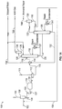
FIGS. 1A and1B , a schematic diagram of a conventional two-column sour water stripping system illustrates the four processing stages. The following pressures and temperatures are exemplary and only for purposes of illustration. -
Sour water feeds 102 from a single or several sources are combined with arecycle stream 104 from theNH3 stripper 106, which are cooled and passed through adegasser 108 where dissolved hydrogen (H2), methane (CH4) and other light hydrocarbons are removed as ahydrocarbon vapor stream 105. Thesour water feeds 102 include dissolved NH3 and H2S. Therecycle stream 104 includes rich NH3, which helps keep acid gases in solution in thedegasser 108, thereby minimizing the release of acid gas and possible air pollution. The degassedsour water stream 109 is sent to adeoiler 103, which removes free oil from the degassedsour water stream 109 to produce a degassed/deoiledsour water stream 107. The degassed/deoiledsour water stream 107 is pumped to afeed preparation tank 110, which serves to attenuate flow rate and composition changes while also providing the opportunity to remove entrained oil and solids. Thefeed preparation tank 110 produces a processedsour water stream 111, which is pumped to afeed coalescer unit 112 that filters solids remaining in the processedsour water stream 111 and further separates entrained oil to produce ahydrocarbon liquid 113 and a deoiledsour water stream 115. The deoiledsour water stream 115 is sent to a feed/product exchanger 114, which acts as a heat exchanger to heat the deoiledsour water stream 115 and cool the NH3stripper bottoms stream 132 to produce a heated deoiledsour water stream 116 and the strippedwater stream 134. In this manner, the components comprising the NH3stripper bottoms stream 132, strippedwater stream 134 and the components comprising the deoiledsour water stream 115, heated deoiledsour water stream 116 are, respectively, the same but may have different concentrations and temperatures. The heated deoiledsour water stream 116 is then sent to anH2S stripper 118. - The
H2S stripper 118 contains trays or packing (not shown) that the heated deoiledsour water stream 116 flows through and around to separate H2S from the heated deoiledsour water stream 116. A cooled reflux water stream (e.g. water wash) 136 is used remove heat and suppress evolution of gaseous NH3 in the H2S stripper. Areboiler 137 acts as a heat exchanger to provide the energy required to i) heat the heated deoiledsour water stream 116 and the cooledreflux water stream 136 to a preferred temperature; and ii) strip out H2S from the heated deoiledsour water stream 116. The resulting H2Sstripper overheads stream 120 is sent to a knock outdrum 138 to substantially remove any entrained droplets and produceH2S stream 126. TheH2S stream 126 is of high purity and is an excellent feed for a sulfur recovery unit (SRU) or a sulfuric acid plant. It contains a negligible amount of NH3 (less than 50 ppmw) and very little hydrocarbons since thesour water feeds 102 have been degassed. TheH2S stream 126 is available at about 6.89-12.4 barg (100-180 psig) and 37.8-48.9°C (100-120°F) The resulting H2Sstripper bottoms stream 130, which contains NH3 and some H2S, is sent directly to theNH3 stripper 106. NH3 Stripping: - The
NH3 stripper 106 is a steam re-boiled, refluxed distillation column. In theNH3 stripper 106, essentially all NH3 and any remaining H2S are removed from the H2Sstripper bottoms stream 130, which leaves theNH3 stripper 106 as an NH3stripper bottoms stream 132. The NH3stripper bottoms stream 132 is sent to the feed/product exchanger 114 where heat is exchanged with the deoiledsour water stream 115 and the NH3stripper bottoms stream 132 is cooled to form the strippedwater stream 134. The strippedwater stream 134 is suitable for many plant reuse needs or may be discharged. The containment levels of H2S and NH3 in the strippedwater stream 134 may be tailored to individual requirements and is typically 10-50 ppmw NH3 and 1-25 ppmw H2S. The strippedwater stream 134 is available at about 37.8-93.3°C (100-200°F). In theNH3 stripper 106, essentially all NH3 and any remaining H2S are removed from the H2Sstripper bottoms stream 130, which leaves theNH3 stripper 106 as an NH3stripper overheads stream 133. The NH3stripper overheads stream 133 is sent to an overhead condenser where it is converted to an NH3 vapor stream and an NH3 liquid stream. A knock outdrum 139 separates the NH3vapor stream 140 and the NH3liquid stream 150. A portion of the NH3liquid stream 150 is returned as reflux to theNH3 stripper 106 and another portion of the NH3liquid stream 150 forms therecycle stream 104. Areboiler 141 acts as a heat exchanger to provide the energy required to remove NH3 and any remaining H2S. The NH3vapor stream 140 is an NH3-rich gas, which may be processed in a variety of ways. - Referring now to
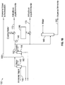
FIG. 1B , theNH3 vapor stream 140 is sent to awater wash 142 to remove residual amounts of H2S and some hydrocarbons. This step is also referred to as water scrubbing, which produces a scrubbedNH3 vapor stream 160. If NH3 recovery is not desired or economic, the scrubbedNH3 vapor stream 160 may be incinerated. In most cases, however, it is desirable to further purify the scrubbedNH3 vapor stream 160 to produce eitheranhydrous liquid NH3 170 or aqueous NH3 180 suitable for commercial use. In order to further purify the scrubbedNH3 vapor stream 160, the scrubbedNH3 vapor stream 160 is sent to acaustic wash 144 to remove residual contaminants including some hydrocarbons. This step is also referred to as caustic scrubbing, which produces a double scrubbedNH3 vapor stream 162 and may be necessary when problems are expected with process upsets, carbon dioxide, or complex sulfur compounds (e.g. mercaptans or disulfides). The double scrubbedNH3 vapor stream 162 may be sent to either acompressor 146 or arefrigeration unit 148 to produce theanhydrous liquid NH3 170, which contains a negligible amount of H2S (less than 5 ppmw). Theanhydrous liquid NH3 170 is available at about 13.8 barg and 37.8°C (200 psig and 100°F) if liquefied by compression and at atmospheric pressure and about -32°C (-26°F) if liquefied by cooling. Cooling water and/or a refrigerant may be used to exchange heat with the compressed double scrubbedNH3 vapor stream 162. The double scrubbedNH3 vapor stream 162 may also be sent to an NH3 absorber 149, which is essentially another water wash, to produce theaqueous NH3 180, which contains a negligible amount of sulfur (no more than about 2ppmw). Theaqueous NH3 180 is available at about 2.4 barg and 37.8°C (35 psig and 100°F) - The present invention overcomes one or more of the prior art disadvantages by providing a method for enhanced separation of H2S and NH3 in an H2S stripper using a stripping gas consisting of carbon dioxide and a gas selected from Hydrogen, Helium, Neon, Argon, Krypton, Radon, diatomic nitrogen, methane and ethane.
- Also disclosed, but not claimed, is a system for separating hydrogen sulfide and ammonia, which comprises: i) a hydrogen sulfide stripper for separating the hydrogen sulfide and the ammonia; and ii) a stripping gas stream connected to the hydrogen sulfide stripper, wherein the stripping gas stream consists of carbon dioxide and a gas selected from Hydrogen, Helium, Neon, Argon, Krypton, Radon, diatomic nitrogen, methane and ethane.
- The present invention is a method for separating hydrogen sulfide and ammonia, which comprises: i) introducing a sour water mixture of the hydrogen sulfide and the ammonia into a hydrogen sulfide stripper; ii) introducing a stripping gas into the hydrogen sulfide stripper, wherein the Stripping gas consists of carbon dioxide and a gas selected from Hydrogen, Helium, Neon, Argon, Krypton, Radon, diatomic nitrogen, methane and ethane; and iii) separating most of the hydrogen sulfide and the ammonia in the sour water mixture using the stripping gas in the hydrogen sulfide stripper, which forms a hydrogen sulfide stripper overheads stream and a hydrogen sulfide stripper bottoms stream
- Additional aspects, advantages and embodiments of the invention will become apparent to those skilled in the art from the following description of the various embodiments and related drawings.
- The present invention is described below with references to the accompanying drawings in which like elements are referenced with like numerals and in which:
-
FIGS. 1A-1B are schematic diagrams illustrating a conventional two-column sour water stripping system. -
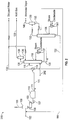
FIG. 2 is a schematic diagram illustrating the H2S stripping stage inFIG. 1A for use in the method of the present invention. - The subject matter of the present invention is described with specificity, however, the description itself is not intended to limit the scope of the invention. The subject matter thus, might also be embodied in other ways, to include different steps or combinations of steps similar to the ones described herein, in conjunction with other technologies. Moreover, although the term "step" may be used herein to describe different elements of methods employed, the term should not be interpreted as implying any particular order among or between various steps herein disclosed unless otherwise expressly limited by the description to a particular order. While the following description refers to the oil and gas industry, the systems and methods of the present invention are not limited thereto and may also be applied in other industries to achieve similar results.
- The present invention provides systems and methods to enhance the separation of H2S and NH3 in an H2S stripper using carbon dioxide and a gas selected from Hydrogen, Helium, Neon, Argon, Krypton, Radon, diatomic nitrogen, methane and ethane. The purpose of the carbon dioxide and the gas selected from Hydrogen, Helium, Neon, Argon, Krypton, Radon, diatomic nitrogen, methane and ethane, also referred to as a stripping gas, is to enhance the separation of H2S and NH3 during the H2S stripping stage by i) lowering the partial pressure of H2S; and ii) providing a stripping action.
- Referring now to
FIG. 2 , a schematic diagram of the H2S stripping stage inFIG. 1A illustrates the use of a strippinggas stream 202 to enhance the separation of H2S and NH3 in theH2S stripper 118. This stage can consist of various pieces of equipment depending upon the ultimate concentration and quality of NH3 desired. The strippinggas stream 202 may be introduced anywhere between the top and bottom of theH2S stripper 118. Preferably, however, the strippinggas stream 202 is introduced near the bottom of theH2S stripper 118 because it will contact more of the heated deoiledsour water stream 116. In this manner, any conventional two-column sour water stripping system that includes a H2S stripping stage may be easily retrofitted with the introduction of a stripping gas. - The stripping
gas stream 202 consists of carbon dioxide and an inert gas, which is a gas that does not react with other constituents of theH2S stripper 118 or sour water stripper, wherein the inert gas is selected from Hydrogen, Helium, Neon, Argon, Krypton, Radon, diatomic nitrogen, methane and ethane. - In the operation of a two-column sour water stripping system with an H2S stripping stage that includes a stripping
gas stream 202 comprising carbon dioxide, the separation of the H2S and NH3 may be improved by at least five percent. By enhancing the separation of H2S and NH3 in this manner, the consumption of utilities (e.g. reboiler heating media) in the two-column sour water stripping system will be lowered resulting in energy savings or performance may be improved with the same utility consumption. - Conventional two-column sour water stripping systems have been around since the 1960's. While operators of such systems have recognized the need for enhanced separation of H2S and NH3, the characteristics of carbon dioxide are similar to those of an acid gas. This explains why the need for enhanced separation of H2S and NH3 using carbon dioxide in the H2S stripping stage of a two-column sour water stripping system, with another acid gas (H2S), has been unresolved since the 1960's.
Claims (6)
- A method for separating hydrogen sulfide and ammonia, which comprises:introducing a sour water mixture of the hydrogen sulfide and the ammonia into a hydrogen sulfide stripper;introducing a stripping gas into the hydrogen sulfide stripper, wherein the stripping gas consists of carbon dioxide and a gas selected from Hydrogen, Helium, Neon, Argon, Krypton, Radon, diatomic nitrogen, methane and ethane; andseparating most of the hydrogen sulfide and the ammonia in the sour water mixture using the stripping gas in the hydrogen sulfide stripper, which forms a hydrogen sulfide stripper overheads stream and a hydrogen sulfide stripper bottoms stream.
- The method of claim 1, wherein the hydrogen sulfide stripper overheads stream comprises the most hydrogen sulfide from the sour water mixture and the hydrogen sulfide stripper bottoms stream comprises the most ammonia from the sour water mixture.
- The method of claim 1, wherein the stripping gas stream comprises equal amounts of the carbon dioxide and gas selected from Hydrogen, Helium, Neon, Argon, Krypton, Radon, diatomic nitrogen, methane, and ethane.
- The method of claim 1, wherein the stripping gas stream comprises more carbon dioxide than the gas selected from Hydrogen, Helium, Neon, Argon, Krypton, Radon, diatomic nitrogen, methane and ethane.
- The method of claim 1, wherein the stripping gas stream comprises more of the gas selected from Hydrogen, Helium, Neon, Argon, Krypton, Radon, diatomic nitrogen, methane and ethane than carbon dioxide.
- The method of claim 1, wherein the hydrogen sulfide stripper contains a fluid mixture of the hydrogen sulfide and the ammonia.
Priority Applications (1)
| Application Number | Priority Date | Filing Date | Title |
|---|---|---|---|
| PL15758346T PL3113862T3 (en) | 2014-03-05 | 2015-03-05 | Method for enhanced separation of hydrogen sulfide and ammonia in a hydrogen sulfide stripper |
Applications Claiming Priority (2)
| Application Number | Priority Date | Filing Date | Title |
|---|---|---|---|
| US201461948118P | 2014-03-05 | 2014-03-05 | |
| PCT/US2015/019009 WO2015134774A1 (en) | 2014-03-05 | 2015-03-05 | Systems and methods for enhanced separation of hydrogen sulfide and ammonia in a hydrogen sulfide stripper |
Publications (3)
| Publication Number | Publication Date |
|---|---|
| EP3113862A1 EP3113862A1 (en) | 2017-01-11 |
| EP3113862A4 EP3113862A4 (en) | 2017-10-04 |
| EP3113862B1 true EP3113862B1 (en) | 2021-05-26 |
Family
ID=54055881
Family Applications (1)
| Application Number | Title | Priority Date | Filing Date |
|---|---|---|---|
| EP15758346.9A Active EP3113862B1 (en) | 2014-03-05 | 2015-03-05 | Method for enhanced separation of hydrogen sulfide and ammonia in a hydrogen sulfide stripper |
Country Status (16)
| Country | Link |
|---|---|
| US (2) | US10022650B2 (en) |
| EP (1) | EP3113862B1 (en) |
| JP (1) | JP6423018B2 (en) |
| KR (1) | KR101954391B1 (en) |
| CN (1) | CN106457137B (en) |
| AU (1) | AU2015227041B2 (en) |
| BR (1) | BR112016020166B1 (en) |
| CA (1) | CA2941410C (en) |
| EA (1) | EA201691564A1 (en) |
| ES (1) | ES2881483T3 (en) |
| MX (1) | MX375022B (en) |
| MY (1) | MY174660A (en) |
| PL (1) | PL3113862T3 (en) |
| SA (1) | SA516371792B1 (en) |
| WO (1) | WO2015134774A1 (en) |
| ZA (1) | ZA201606069B (en) |
Families Citing this family (6)
| Publication number | Priority date | Publication date | Assignee | Title |
|---|---|---|---|---|
| PL3113862T3 (en) * | 2014-03-05 | 2021-09-27 | Bechtel Hydrocarbon Technology Solutions, Inc. | Method for enhanced separation of hydrogen sulfide and ammonia in a hydrogen sulfide stripper |
| CN108025245B (en) * | 2015-06-10 | 2021-03-05 | 贝克特尔碳氢技术解决方案股份有限公司 | For high CO2System and method for ammonia purification |
| US10221075B1 (en) * | 2018-01-25 | 2019-03-05 | Benjamin Fannin Bachman | Synthesis of ammonia from hydrogen sulfide |
| CN109534569B (en) * | 2018-11-08 | 2022-05-31 | 中科合成油工程有限公司 | Method for treating waste water containing acid and ammonia and equipment system for implementing method |
| US20230295011A1 (en) * | 2022-03-21 | 2023-09-21 | Saudi Arabian Oil Company | Injection of Off-Gas from Sour Water Stripper |
| KR20250172694A (en) * | 2022-11-15 | 2025-12-09 | 벡텔 에너지 테크놀로지스 앤 솔루션스, 아이엔씨. | Systems and methods for ammonia purification |
Citations (1)
| Publication number | Priority date | Publication date | Assignee | Title |
|---|---|---|---|---|
| US3984316A (en) * | 1975-07-30 | 1976-10-05 | Ashland Oil, Inc. | Treating foul refinery waste waters with absorber gas |
Family Cites Families (22)
| Publication number | Priority date | Publication date | Assignee | Title |
|---|---|---|---|---|
| US3754376A (en) * | 1972-02-01 | 1973-08-28 | Texaco Inc | Inert gas stripping of contaminated water |
| GB1471195A (en) * | 1973-07-25 | 1977-04-21 | Exxon Research Engineering Co | Process for the removal of a salt of a weak acid and weak base from a solution |
| US4242108A (en) * | 1979-11-07 | 1980-12-30 | Air Products And Chemicals, Inc. | Hydrogen sulfide concentrator for acid gas removal systems |
| US4469668A (en) * | 1982-01-29 | 1984-09-04 | Spevack Jerome S | Integrated system for pollution abatement and energy derivation from geothermal steam |
| US4414103A (en) | 1982-04-09 | 1983-11-08 | Chevron Research Company | Selective removal and recovery of ammonia and hydrogen sulfide |
| JPH0768527B2 (en) * | 1990-05-29 | 1995-07-26 | 宇部興産株式会社 | Recovery Method of Ammonium Carbonate from Process Drain of Coal Partial Oxidation Furnace |
| US5368754A (en) | 1990-11-01 | 1994-11-29 | Texaco Inc. | Method for stripping contaminants from wastewater |
| DE4041569A1 (en) * | 1990-12-22 | 1992-06-25 | Hoechst Ag | METHOD FOR PROCESSING SULFUR HYDROGEN, CYAN HYDROGEN AND AMMONIA CONTAINING AQUEOUS SOLUTIONS |
| DE4238289C2 (en) * | 1992-11-13 | 1997-02-06 | Rheinische Braunkohlenw Ag | Process and plant for the pretreatment of process wastewater |
| US7153427B2 (en) * | 2002-07-22 | 2006-12-26 | Environmental Energy & Engineering Co. | Nitrogen recovery system and method using heated air as stripping gas |
| US20120039792A1 (en) | 2004-12-30 | 2012-02-16 | Gheorghe Duta | Method for ground water and wastewater treatment |
| US7258848B1 (en) * | 2006-07-31 | 2007-08-21 | E. I. Du Pont De Nemours And Company | Process for scrubbing ammonia from acid gases comprising ammonia and hydrogen sulfide |
| TW201002680A (en) * | 2008-03-27 | 2010-01-16 | Solvay Fluor Gmbh | Process for the removal of HF from HF containing organic carbonates |
| JP2010221106A (en) * | 2009-03-23 | 2010-10-07 | Kurimoto Ltd | Stripping device |
| IT1397745B1 (en) * | 2010-01-22 | 2013-01-24 | Siirtec Nigi S P A | INTEGRATED PROCESS OF PURIFICATION OF REFINERY WATERS, CONTAINING PRECISELY AMMONIA AND SULFIDRIC ACID, AND OF GAS ACIDS CONTAINING PREVIOUSLY SULFIDRIC ACID. |
| US20110272365A1 (en) | 2010-05-07 | 2011-11-10 | Encana Corporation | Removal of hydrogen sulfide from water |
| US9028678B2 (en) * | 2011-06-28 | 2015-05-12 | Phillips 66 Company | Scrubbing hydrogen sulfide from hydrotreated product |
| US20130243677A1 (en) * | 2012-03-14 | 2013-09-19 | Exxonmobil Research And Engineering Company | Amine treating process for selective acid gas separation |
| US8945292B2 (en) * | 2012-03-23 | 2015-02-03 | General Electric Company | System for recovering acid gases from a gas stream |
| CN103611391B (en) * | 2013-12-12 | 2016-01-20 | 北京博源恒升高科技有限公司 | Glycols composite solution removes the method for SOx in gas |
| PL3113862T3 (en) * | 2014-03-05 | 2021-09-27 | Bechtel Hydrocarbon Technology Solutions, Inc. | Method for enhanced separation of hydrogen sulfide and ammonia in a hydrogen sulfide stripper |
| JP7073699B2 (en) * | 2017-12-08 | 2022-05-24 | ブラザー工業株式会社 | Image processing program, information processing device and image processing method |
-
2015
- 2015-03-05 PL PL15758346T patent/PL3113862T3/en unknown
- 2015-03-05 CA CA2941410A patent/CA2941410C/en active Active
- 2015-03-05 ES ES15758346T patent/ES2881483T3/en active Active
- 2015-03-05 JP JP2016573689A patent/JP6423018B2/en active Active
- 2015-03-05 EA EA201691564A patent/EA201691564A1/en unknown
- 2015-03-05 WO PCT/US2015/019009 patent/WO2015134774A1/en not_active Ceased
- 2015-03-05 CN CN201580011778.5A patent/CN106457137B/en active Active
- 2015-03-05 AU AU2015227041A patent/AU2015227041B2/en active Active
- 2015-03-05 MY MYPI2016001594A patent/MY174660A/en unknown
- 2015-03-05 US US15/123,546 patent/US10022650B2/en active Active
- 2015-03-05 KR KR1020167027498A patent/KR101954391B1/en not_active Expired - Fee Related
- 2015-03-05 EP EP15758346.9A patent/EP3113862B1/en active Active
- 2015-03-05 BR BR112016020166-3A patent/BR112016020166B1/en active IP Right Grant
- 2015-03-05 MX MX2016011397A patent/MX375022B/en active IP Right Grant
-
2016
- 2016-09-01 ZA ZA2016/06069A patent/ZA201606069B/en unknown
- 2016-09-04 SA SA516371792A patent/SA516371792B1/en unknown
-
2018
- 2018-06-19 US US16/012,261 patent/US10702799B2/en active Active
Patent Citations (1)
| Publication number | Priority date | Publication date | Assignee | Title |
|---|---|---|---|---|
| US3984316A (en) * | 1975-07-30 | 1976-10-05 | Ashland Oil, Inc. | Treating foul refinery waste waters with absorber gas |
Also Published As
| Publication number | Publication date |
|---|---|
| MY174660A (en) | 2020-05-05 |
| BR112016020166A2 (en) | 2017-08-15 |
| KR101954391B1 (en) | 2019-03-05 |
| US10022650B2 (en) | 2018-07-17 |
| EP3113862A4 (en) | 2017-10-04 |
| ZA201606069B (en) | 2019-04-24 |
| MX375022B (en) | 2025-03-06 |
| US10702799B2 (en) | 2020-07-07 |
| AU2015227041A1 (en) | 2016-09-22 |
| ES2881483T8 (en) | 2022-01-31 |
| WO2015134774A1 (en) | 2015-09-11 |
| JP6423018B2 (en) | 2018-11-14 |
| KR20160127819A (en) | 2016-11-04 |
| US20180296944A1 (en) | 2018-10-18 |
| AU2015227041B2 (en) | 2018-02-15 |
| CN106457137B (en) | 2020-08-07 |
| BR112016020166B1 (en) | 2022-11-01 |
| CA2941410A1 (en) | 2015-09-11 |
| CA2941410C (en) | 2019-02-26 |
| CN106457137A (en) | 2017-02-22 |
| MX2016011397A (en) | 2016-12-02 |
| PL3113862T3 (en) | 2021-09-27 |
| EA201691564A1 (en) | 2017-02-28 |
| ES2881483T3 (en) | 2021-11-29 |
| SA516371792B1 (en) | 2019-06-18 |
| EP3113862A1 (en) | 2017-01-11 |
| JP2017510454A (en) | 2017-04-13 |
| US20170072338A1 (en) | 2017-03-16 |
Similar Documents
| Publication | Publication Date | Title |
|---|---|---|
| US10702799B2 (en) | Systems and methods for enhanced separation of hydrogen sulfide and ammonia in a hydrogen sulfide stripper | |
| US10843122B2 (en) | Systems and methods for removing hydrogen sulfide from an ammonia stream | |
| EP3114084B1 (en) | Systems and methods for ammonia purification | |
| US10850226B2 (en) | Systems and methods for high CO2 ammonia purification | |
| KR20250177461A (en) | Systems and methods for ammonia purification | |
| CN111393248A (en) | Device and method for oil gas desulfurization and light hydrocarbon recovery |
Legal Events
| Date | Code | Title | Description |
|---|---|---|---|
| STAA | Information on the status of an ep patent application or granted ep patent |
Free format text: STATUS: THE INTERNATIONAL PUBLICATION HAS BEEN MADE |
|
| PUAI | Public reference made under article 153(3) epc to a published international application that has entered the european phase |
Free format text: ORIGINAL CODE: 0009012 |
|
| STAA | Information on the status of an ep patent application or granted ep patent |
Free format text: STATUS: REQUEST FOR EXAMINATION WAS MADE |
|
| 17P | Request for examination filed |
Effective date: 20160923 |
|
| AK | Designated contracting states |
Kind code of ref document: A1 Designated state(s): AL AT BE BG CH CY CZ DE DK EE ES FI FR GB GR HR HU IE IS IT LI LT LU LV MC MK MT NL NO PL PT RO RS SE SI SK SM TR |
|
| AX | Request for extension of the european patent |
Extension state: BA ME |
|
| DAV | Request for validation of the european patent (deleted) | ||
| DAX | Request for extension of the european patent (deleted) | ||
| A4 | Supplementary search report drawn up and despatched |
Effective date: 20170831 |
|
| RIC1 | Information provided on ipc code assigned before grant |
Ipc: C02F 101/10 20060101ALN20170825BHEP Ipc: C02F 1/20 20060101ALI20170825BHEP Ipc: B01D 19/00 20060101ALI20170825BHEP Ipc: B01D 53/52 20060101AFI20170825BHEP Ipc: C02F 103/36 20060101ALI20170825BHEP Ipc: B01D 53/14 20060101ALI20170825BHEP Ipc: C01C 1/12 20060101ALI20170825BHEP Ipc: C02F 101/16 20060101ALN20170825BHEP |
|
| STAA | Information on the status of an ep patent application or granted ep patent |
Free format text: STATUS: EXAMINATION IS IN PROGRESS |
|
| 17Q | First examination report despatched |
Effective date: 20190313 |
|
| RIC1 | Information provided on ipc code assigned before grant |
Ipc: B01D 19/00 20060101ALI20201009BHEP Ipc: C01C 1/12 20060101ALI20201009BHEP Ipc: C02F 1/20 20060101ALI20201009BHEP Ipc: C02F 101/10 20060101ALN20201009BHEP Ipc: B01D 53/52 20060101AFI20201009BHEP Ipc: C02F 103/36 20060101ALI20201009BHEP Ipc: B01D 53/14 20060101ALI20201009BHEP Ipc: C02F 101/16 20060101ALN20201009BHEP |
|
| RIC1 | Information provided on ipc code assigned before grant |
Ipc: C02F 103/36 20060101ALI20201102BHEP Ipc: C02F 101/10 20060101ALN20201102BHEP Ipc: C01C 1/12 20060101ALI20201102BHEP Ipc: B01D 53/14 20060101ALI20201102BHEP Ipc: B01D 53/52 20060101AFI20201102BHEP Ipc: B01D 19/00 20060101ALI20201102BHEP Ipc: C02F 1/20 20060101ALI20201102BHEP Ipc: C02F 101/16 20060101ALN20201102BHEP |
|
| GRAP | Despatch of communication of intention to grant a patent |
Free format text: ORIGINAL CODE: EPIDOSNIGR1 |
|
| STAA | Information on the status of an ep patent application or granted ep patent |
Free format text: STATUS: GRANT OF PATENT IS INTENDED |
|
| RIC1 | Information provided on ipc code assigned before grant |
Ipc: C02F 103/36 20060101ALI20201123BHEP Ipc: B01D 53/52 20060101AFI20201123BHEP Ipc: C02F 101/16 20060101ALN20201123BHEP Ipc: C01C 1/12 20060101ALI20201123BHEP Ipc: C02F 1/20 20060101ALI20201123BHEP Ipc: B01D 19/00 20060101ALI20201123BHEP Ipc: B01D 53/14 20060101ALI20201123BHEP Ipc: C02F 101/10 20060101ALN20201123BHEP |
|
| INTG | Intention to grant announced |
Effective date: 20201216 |
|
| GRAS | Grant fee paid |
Free format text: ORIGINAL CODE: EPIDOSNIGR3 |
|
| GRAA | (expected) grant |
Free format text: ORIGINAL CODE: 0009210 |
|
| STAA | Information on the status of an ep patent application or granted ep patent |
Free format text: STATUS: THE PATENT HAS BEEN GRANTED |
|
| AK | Designated contracting states |
Kind code of ref document: B1 Designated state(s): AL AT BE BG CH CY CZ DE DK EE ES FI FR GB GR HR HU IE IS IT LI LT LU LV MC MK MT NL NO PL PT RO RS SE SI SK SM TR |
|
| REG | Reference to a national code |
Ref country code: GB Ref legal event code: FG4D |
|
| REG | Reference to a national code |
Ref country code: CH Ref legal event code: EP |
|
| REG | Reference to a national code |
Ref country code: AT Ref legal event code: REF Ref document number: 1395653 Country of ref document: AT Kind code of ref document: T Effective date: 20210615 |
|
| REG | Reference to a national code |
Ref country code: DE Ref legal event code: R096 Ref document number: 602015069728 Country of ref document: DE |
|
| REG | Reference to a national code |
Ref country code: IE Ref legal event code: FG4D |
|
| REG | Reference to a national code |
Ref country code: FI Ref legal event code: FGE |
|
| REG | Reference to a national code |
Ref country code: NL Ref legal event code: FP |
|
| REG | Reference to a national code |
Ref country code: SE Ref legal event code: TRGR |
|
| REG | Reference to a national code |
Ref country code: LT Ref legal event code: MG9D |
|
| REG | Reference to a national code |
Ref country code: GR Ref legal event code: EP Ref document number: 20210402122 Country of ref document: GR Effective date: 20210915 |
|
| REG | Reference to a national code |
Ref country code: AT Ref legal event code: MK05 Ref document number: 1395653 Country of ref document: AT Kind code of ref document: T Effective date: 20210526 |
|
| PG25 | Lapsed in a contracting state [announced via postgrant information from national office to epo] |
Ref country code: LT Free format text: LAPSE BECAUSE OF FAILURE TO SUBMIT A TRANSLATION OF THE DESCRIPTION OR TO PAY THE FEE WITHIN THE PRESCRIBED TIME-LIMIT Effective date: 20210526 Ref country code: BG Free format text: LAPSE BECAUSE OF FAILURE TO SUBMIT A TRANSLATION OF THE DESCRIPTION OR TO PAY THE FEE WITHIN THE PRESCRIBED TIME-LIMIT Effective date: 20210826 Ref country code: AT Free format text: LAPSE BECAUSE OF FAILURE TO SUBMIT A TRANSLATION OF THE DESCRIPTION OR TO PAY THE FEE WITHIN THE PRESCRIBED TIME-LIMIT Effective date: 20210526 Ref country code: HR Free format text: LAPSE BECAUSE OF FAILURE TO SUBMIT A TRANSLATION OF THE DESCRIPTION OR TO PAY THE FEE WITHIN THE PRESCRIBED TIME-LIMIT Effective date: 20210526 |
|
| REG | Reference to a national code |
Ref country code: ES Ref legal event code: FG2A Ref document number: 2881483 Country of ref document: ES Kind code of ref document: T3 Effective date: 20211129 |
|
| PG25 | Lapsed in a contracting state [announced via postgrant information from national office to epo] |
Ref country code: IS Free format text: LAPSE BECAUSE OF FAILURE TO SUBMIT A TRANSLATION OF THE DESCRIPTION OR TO PAY THE FEE WITHIN THE PRESCRIBED TIME-LIMIT Effective date: 20210926 Ref country code: LV Free format text: LAPSE BECAUSE OF FAILURE TO SUBMIT A TRANSLATION OF THE DESCRIPTION OR TO PAY THE FEE WITHIN THE PRESCRIBED TIME-LIMIT Effective date: 20210526 Ref country code: NO Free format text: LAPSE BECAUSE OF FAILURE TO SUBMIT A TRANSLATION OF THE DESCRIPTION OR TO PAY THE FEE WITHIN THE PRESCRIBED TIME-LIMIT Effective date: 20210826 Ref country code: PT Free format text: LAPSE BECAUSE OF FAILURE TO SUBMIT A TRANSLATION OF THE DESCRIPTION OR TO PAY THE FEE WITHIN THE PRESCRIBED TIME-LIMIT Effective date: 20210927 Ref country code: RS Free format text: LAPSE BECAUSE OF FAILURE TO SUBMIT A TRANSLATION OF THE DESCRIPTION OR TO PAY THE FEE WITHIN THE PRESCRIBED TIME-LIMIT Effective date: 20210526 |
|
| PG25 | Lapsed in a contracting state [announced via postgrant information from national office to epo] |
Ref country code: RO Free format text: LAPSE BECAUSE OF FAILURE TO SUBMIT A TRANSLATION OF THE DESCRIPTION OR TO PAY THE FEE WITHIN THE PRESCRIBED TIME-LIMIT Effective date: 20210526 Ref country code: DK Free format text: LAPSE BECAUSE OF FAILURE TO SUBMIT A TRANSLATION OF THE DESCRIPTION OR TO PAY THE FEE WITHIN THE PRESCRIBED TIME-LIMIT Effective date: 20210526 Ref country code: EE Free format text: LAPSE BECAUSE OF FAILURE TO SUBMIT A TRANSLATION OF THE DESCRIPTION OR TO PAY THE FEE WITHIN THE PRESCRIBED TIME-LIMIT Effective date: 20210526 Ref country code: CZ Free format text: LAPSE BECAUSE OF FAILURE TO SUBMIT A TRANSLATION OF THE DESCRIPTION OR TO PAY THE FEE WITHIN THE PRESCRIBED TIME-LIMIT Effective date: 20210526 Ref country code: SM Free format text: LAPSE BECAUSE OF FAILURE TO SUBMIT A TRANSLATION OF THE DESCRIPTION OR TO PAY THE FEE WITHIN THE PRESCRIBED TIME-LIMIT Effective date: 20210526 Ref country code: SK Free format text: LAPSE BECAUSE OF FAILURE TO SUBMIT A TRANSLATION OF THE DESCRIPTION OR TO PAY THE FEE WITHIN THE PRESCRIBED TIME-LIMIT Effective date: 20210526 |
|
| REG | Reference to a national code |
Ref country code: DE Ref legal event code: R097 Ref document number: 602015069728 Country of ref document: DE |
|
| PLBE | No opposition filed within time limit |
Free format text: ORIGINAL CODE: 0009261 |
|
| STAA | Information on the status of an ep patent application or granted ep patent |
Free format text: STATUS: NO OPPOSITION FILED WITHIN TIME LIMIT |
|
| 26N | No opposition filed |
Effective date: 20220301 |
|
| PG25 | Lapsed in a contracting state [announced via postgrant information from national office to epo] |
Ref country code: IS Free format text: LAPSE BECAUSE OF FAILURE TO SUBMIT A TRANSLATION OF THE DESCRIPTION OR TO PAY THE FEE WITHIN THE PRESCRIBED TIME-LIMIT Effective date: 20210926 Ref country code: AL Free format text: LAPSE BECAUSE OF FAILURE TO SUBMIT A TRANSLATION OF THE DESCRIPTION OR TO PAY THE FEE WITHIN THE PRESCRIBED TIME-LIMIT Effective date: 20210526 |
|
| REG | Reference to a national code |
Ref country code: DE Ref legal event code: R081 Ref document number: 602015069728 Country of ref document: DE Owner name: BECHTEL ENERGY TECHNOLOGIES & SOLUTIONS, INC. , US Free format text: FORMER OWNER: BECHTEL HYDROCARBON TECHNOLOGY SOLUTIONS, INC., HOUSTON, TX, US |
|
| REG | Reference to a national code |
Ref country code: NL Ref legal event code: HC Owner name: BECHTEL ENERGY TECHNOLOGIES & SOLUTIONS, INC.; US Free format text: DETAILS ASSIGNMENT: CHANGE OF OWNER(S), CHANGE OF OWNER(S) NAME; FORMER OWNER NAME: BECHTEL HYDROCARBON TECHNOLOGY SOLUTIONS, INC. Effective date: 20220905 |
|
| PG25 | Lapsed in a contracting state [announced via postgrant information from national office to epo] |
Ref country code: MC Free format text: LAPSE BECAUSE OF FAILURE TO SUBMIT A TRANSLATION OF THE DESCRIPTION OR TO PAY THE FEE WITHIN THE PRESCRIBED TIME-LIMIT Effective date: 20210526 |
|
| REG | Reference to a national code |
Ref country code: CH Ref legal event code: PL |
|
| REG | Reference to a national code |
Ref country code: BE Ref legal event code: MM Effective date: 20220331 |
|
| PG25 | Lapsed in a contracting state [announced via postgrant information from national office to epo] |
Ref country code: LU Free format text: LAPSE BECAUSE OF NON-PAYMENT OF DUE FEES Effective date: 20220305 Ref country code: LI Free format text: LAPSE BECAUSE OF NON-PAYMENT OF DUE FEES Effective date: 20220331 Ref country code: IE Free format text: LAPSE BECAUSE OF NON-PAYMENT OF DUE FEES Effective date: 20220305 Ref country code: CH Free format text: LAPSE BECAUSE OF NON-PAYMENT OF DUE FEES Effective date: 20220331 |
|
| PG25 | Lapsed in a contracting state [announced via postgrant information from national office to epo] |
Ref country code: BE Free format text: LAPSE BECAUSE OF NON-PAYMENT OF DUE FEES Effective date: 20220331 |
|
| REG | Reference to a national code |
Ref country code: ES Ref legal event code: PC2A Owner name: BECHTEL ENERGY TECHNOLOGIES & SOLUTIONS, INC. Effective date: 20230529 |
|
| P01 | Opt-out of the competence of the unified patent court (upc) registered |
Effective date: 20230907 |
|
| PG25 | Lapsed in a contracting state [announced via postgrant information from national office to epo] |
Ref country code: HU Free format text: LAPSE BECAUSE OF FAILURE TO SUBMIT A TRANSLATION OF THE DESCRIPTION OR TO PAY THE FEE WITHIN THE PRESCRIBED TIME-LIMIT; INVALID AB INITIO Effective date: 20150305 |
|
| PG25 | Lapsed in a contracting state [announced via postgrant information from national office to epo] |
Ref country code: MK Free format text: LAPSE BECAUSE OF FAILURE TO SUBMIT A TRANSLATION OF THE DESCRIPTION OR TO PAY THE FEE WITHIN THE PRESCRIBED TIME-LIMIT Effective date: 20210526 Ref country code: CY Free format text: LAPSE BECAUSE OF FAILURE TO SUBMIT A TRANSLATION OF THE DESCRIPTION OR TO PAY THE FEE WITHIN THE PRESCRIBED TIME-LIMIT Effective date: 20210526 |
|
| PG25 | Lapsed in a contracting state [announced via postgrant information from national office to epo] |
Ref country code: MT Free format text: LAPSE BECAUSE OF FAILURE TO SUBMIT A TRANSLATION OF THE DESCRIPTION OR TO PAY THE FEE WITHIN THE PRESCRIBED TIME-LIMIT Effective date: 20210526 |
|
| PGFP | Annual fee paid to national office [announced via postgrant information from national office to epo] |
Ref country code: ES Payment date: 20250414 Year of fee payment: 11 |
|
| PG25 | Lapsed in a contracting state [announced via postgrant information from national office to epo] |
Ref country code: TR Free format text: LAPSE BECAUSE OF FAILURE TO SUBMIT A TRANSLATION OF THE DESCRIPTION OR TO PAY THE FEE WITHIN THE PRESCRIBED TIME-LIMIT Effective date: 20210526 |
|
| PGFP | Annual fee paid to national office [announced via postgrant information from national office to epo] |
Ref country code: FI Payment date: 20251230 Year of fee payment: 12 |
|
| PGFP | Annual fee paid to national office [announced via postgrant information from national office to epo] |
Ref country code: FR Payment date: 20251231 Year of fee payment: 12 |
|
| PGFP | Annual fee paid to national office [announced via postgrant information from national office to epo] |
Ref country code: NL Payment date: 20260106 Year of fee payment: 12 |
|
| PGFP | Annual fee paid to national office [announced via postgrant information from national office to epo] |
Ref country code: SE Payment date: 20260105 Year of fee payment: 12 |
|
| PGFP | Annual fee paid to national office [announced via postgrant information from national office to epo] |
Ref country code: GB Payment date: 20260106 Year of fee payment: 12 |
|
| PGFP | Annual fee paid to national office [announced via postgrant information from national office to epo] |
Ref country code: DE Payment date: 20260102 Year of fee payment: 12 |
|
| PGFP | Annual fee paid to national office [announced via postgrant information from national office to epo] |
Ref country code: IT Payment date: 20260220 Year of fee payment: 12 |
|
| PGFP | Annual fee paid to national office [announced via postgrant information from national office to epo] |
Ref country code: GR Payment date: 20260211 Year of fee payment: 12 Ref country code: PL Payment date: 20260116 Year of fee payment: 12 |