EP3113717B1 - Dental implant - Google Patents
Dental implant Download PDFInfo
- Publication number
- EP3113717B1 EP3113717B1 EP15710139.5A EP15710139A EP3113717B1 EP 3113717 B1 EP3113717 B1 EP 3113717B1 EP 15710139 A EP15710139 A EP 15710139A EP 3113717 B1 EP3113717 B1 EP 3113717B1
- Authority
- EP
- European Patent Office
- Prior art keywords
- implant
- apical
- coronal
- flute
- thread
- Prior art date
- Legal status (The legal status is an assumption and is not a legal conclusion. Google has not performed a legal analysis and makes no representation as to the accuracy of the status listed.)
- Revoked
Links
Images


Classifications
-
- A—HUMAN NECESSITIES
- A61—MEDICAL OR VETERINARY SCIENCE; HYGIENE
- A61C—DENTISTRY; APPARATUS OR METHODS FOR ORAL OR DENTAL HYGIENE
- A61C8/00—Means to be fixed to the jaw-bone for consolidating natural teeth or for fixing dental prostheses thereon; Dental implants; Implanting tools
- A61C8/0018—Means to be fixed to the jaw-bone for consolidating natural teeth or for fixing dental prostheses thereon; Dental implants; Implanting tools characterised by the shape
-
- A—HUMAN NECESSITIES
- A61—MEDICAL OR VETERINARY SCIENCE; HYGIENE
- A61C—DENTISTRY; APPARATUS OR METHODS FOR ORAL OR DENTAL HYGIENE
- A61C8/00—Means to be fixed to the jaw-bone for consolidating natural teeth or for fixing dental prostheses thereon; Dental implants; Implanting tools
- A61C8/0018—Means to be fixed to the jaw-bone for consolidating natural teeth or for fixing dental prostheses thereon; Dental implants; Implanting tools characterised by the shape
- A61C8/0022—Self-screwing
-
- A—HUMAN NECESSITIES
- A61—MEDICAL OR VETERINARY SCIENCE; HYGIENE
- A61C—DENTISTRY; APPARATUS OR METHODS FOR ORAL OR DENTAL HYGIENE
- A61C8/00—Means to be fixed to the jaw-bone for consolidating natural teeth or for fixing dental prostheses thereon; Dental implants; Implanting tools
- A61C8/0003—Not used, see subgroups
- A61C8/0004—Consolidating natural teeth
- A61C8/0006—Periodontal tissue or bone regeneration
-
- A—HUMAN NECESSITIES
- A61—MEDICAL OR VETERINARY SCIENCE; HYGIENE
- A61C—DENTISTRY; APPARATUS OR METHODS FOR ORAL OR DENTAL HYGIENE
- A61C8/00—Means to be fixed to the jaw-bone for consolidating natural teeth or for fixing dental prostheses thereon; Dental implants; Implanting tools
- A61C8/0018—Means to be fixed to the jaw-bone for consolidating natural teeth or for fixing dental prostheses thereon; Dental implants; Implanting tools characterised by the shape
- A61C8/0022—Self-screwing
- A61C8/0024—Self-screwing with self-boring cutting edge
-
- A—HUMAN NECESSITIES
- A61—MEDICAL OR VETERINARY SCIENCE; HYGIENE
- A61C—DENTISTRY; APPARATUS OR METHODS FOR ORAL OR DENTAL HYGIENE
- A61C8/00—Means to be fixed to the jaw-bone for consolidating natural teeth or for fixing dental prostheses thereon; Dental implants; Implanting tools
- A61C8/0018—Means to be fixed to the jaw-bone for consolidating natural teeth or for fixing dental prostheses thereon; Dental implants; Implanting tools characterised by the shape
- A61C8/0022—Self-screwing
- A61C8/0025—Self-screwing with multiple threads
-
- A—HUMAN NECESSITIES
- A61—MEDICAL OR VETERINARY SCIENCE; HYGIENE
- A61C—DENTISTRY; APPARATUS OR METHODS FOR ORAL OR DENTAL HYGIENE
- A61C8/00—Means to be fixed to the jaw-bone for consolidating natural teeth or for fixing dental prostheses thereon; Dental implants; Implanting tools
- A61C8/0018—Means to be fixed to the jaw-bone for consolidating natural teeth or for fixing dental prostheses thereon; Dental implants; Implanting tools characterised by the shape
- A61C8/0037—Details of the shape
-
- A—HUMAN NECESSITIES
- A61—MEDICAL OR VETERINARY SCIENCE; HYGIENE
- A61C—DENTISTRY; APPARATUS OR METHODS FOR ORAL OR DENTAL HYGIENE
- A61C8/00—Means to be fixed to the jaw-bone for consolidating natural teeth or for fixing dental prostheses thereon; Dental implants; Implanting tools
- A61C8/0048—Connecting the upper structure to the implant, e.g. bridging bars
- A61C8/0078—Connecting the upper structure to the implant, e.g. bridging bars with platform switching, i.e. platform between implant and abutment
-
- A—HUMAN NECESSITIES
- A61—MEDICAL OR VETERINARY SCIENCE; HYGIENE
- A61C—DENTISTRY; APPARATUS OR METHODS FOR ORAL OR DENTAL HYGIENE
- A61C8/00—Means to be fixed to the jaw-bone for consolidating natural teeth or for fixing dental prostheses thereon; Dental implants; Implanting tools
- A61C8/008—Healing caps or the like
Definitions
- the present invention relates to a dental implant for preserving soft tissue health and aesthetics, promoting bone growth and bone augmentation.
- the invention further relates to an implant system.
- One first approach relies on augmentation of the bone tissue using surgical techniques, wherein a second approach concentrates on adapting the design of the implant. For the latter, it is for example possible to change the dimensions of the features of an implant or the implant's surface in order to stimulate osseointegration.
- a successful example of a surface that demonstrated a positive effect on osseointegration is the TiUnite® surface developed and marketed by Nobel Biocare®.
- graft materials used for augmenting are Autografts, Allografts, Xenografts and Alloplasts. It has been shown that these materials have in general a high survival rate once being implanted (see Jensen, O. T.; "Report of the Sinus Consensus Conference of 1996”; Int J Oral Maxillofac Implants. 1998; 13 Suppl:11-45. Review ).
- Autografts require additional surgery, often inflicting pain for the patient and have a limited availability.
- the implant can be made to carry growth stimulating substances that are known to stimulate the formation of bone tissue.
- additional substances may incur cost.
- they since they are directly in contact with blood, and actively initiate a cell and molecular response their clinical use is therefore subject to extensive regulations.
- US 6,604,945 B1 discloses a method and apparatus for embedding an implant in a way that encourages bone tissue growth in and around the implant. This is intended to be achieved by a bone-fragment collecting drill. The collected bone fragments are packed into helical channels and through holes prior the installation of the implant in the implantation hole.
- the bone material used for augmentation is autologous and the collection of bone material still has to be performed during steps that precede the insertion of the implant.
- Bone augmentation may also be desired to improve implant rehabilitation aesthetics. Augmentation of resorbed alveolar ridges or/and alveolar ridges with aberration or/and fresh tooth extraction sockets may be needed in order to support soft tissue contours. Hence, it is desired to develop an implant that is able to stimulate bone growth and without using autografts from a second surgical step.
- US 6,273,722 B1 discloses a dental implant having a body with a diameter that is press fit into a hole drilled into a patient's jaw bone, and having a helical groove machined into the body diameter to improve the rate of growth of bone tissue to securely lock the implant in position.
- a shallow height oppositely wound helical thread may be added to increase the holding force upon initial fitting of the implant.
- the implant of US '722 is a press fit implant, i. e. an implantation hole with precise diameter has to be prepared.
- US '945 the bone tissue taken out to create said hole is completely lost.
- US 6,382,976 B1 discloses a self-tapping dental implant having a round bottom with channels that extend upwardly to communicate with bone cutting flutes horizontally disposed along a tapping end of the implant.
- RO 110899 B1 discloses a self-tapping dental implant comprising an external thread and a flute arrangement with one or more helical flutes. Said flute arrangement is capable of scraping and transferring bone debris in the coronal direction of the implant during insertion.
- the invention pertains to an implant and an implant system as defined in the hereto attached independent claims. Further embodiments also addressing the objectives listed above are stated in the dependent claims.
- the implant provided by the invention is a dental implant for promoting bone growth. It comprises an elongated implant body having a coronal end portion and an apical end portion, at least one external thread, a flute arrangement having a depth.
- the flute arrangement is propagating with a greater lead than the at least one thread, and said flute arrangement is being capable of scraping and transferring bone debris opposite to the insertion direction of the implant during insertion and said flute arrangement having at least two helical flutes that spiral in the direction of said at least one external thread.
- the helical flutes are propagating at least one turn around the implant body like serpentines.
- the helical flute can be made such that the tangent line at any point makes a constant angle with a fixed line, said fixed line propagating along an axis in the longitudinal direction of he implant.
- the helical propagation can be made with some deviations to the mathematical definition of helical and it is acknowledged that the flute can propagate with at least one turn around the axis of the implant and with a lead that on average is greater than the lead of the thread/s of said implant.
- the helical flute collects bone tissue that is cut off during insertion as bone debris.
- the bone debris is transported in the opposite direction of insertion to be deposited in the coronal periphery of the implant in order to promote bone augmentation and bone repair, i. e. the healing reaction taking place post-operative.
- This space may be an implantation hole prepared prior to insertion of the implant by using different known techniques to prepare the site for implantation of a bone implant according to the invention.
- the sockets may not be exactly shaped as to fit the shape of the implant because of wide root canals, and posterior extraction sites often reveal more than one root.
- Other issues to deal with in this regard are alveolar ridge aberrations.
- Incorporating more than one helical flute in the design of the dental implant has the effect that cutting forces during insertion of the implant are basically symmetrical. This facilitates stable insertion of the implant along its longitudinal axis.
- the helical flute has a greater depth than the average thread depth of the implant.
- the depth of the flute is 40% to 200% greater than the average thread depth, more preferably 60% to 150% more deep than the average thread depth.
- the relation of average thread and flute depth has proven more important than expected in providing enough driving force during insertion so as to enable a sufficient cutting and transport of bone debris during insertion of the implant in the hole.
- the thread extends beyond the flute arrangement in the coronal direction. This will help to form a seal by close bone to implant contact at the coronal portion when the implant is in its intended position.
- the flute has a coronal flank and an apical flank, wherein the apical flank provides a cutting edge. Furthermore, an angle ( ⁇ ) as measured in the longitudinal cross section of the implant between the coronal flank of said flute and a normal to the longitudinal axis of said implant is between 0° and 5°, preferably between 1 ° and 3°. The cutting of bone debris and subsequent collection in and transfer via the flutes to allow discharge near the coronal part of the implant is enabled by an angle of the apical flank in said range.
- the at least one flute comprising a flute base between the coronal flank and the apical flank of the flute arrangement, the flute base, as measured in the longitudinal cross section of the implant, preferably being inclined toward the longitudinal axis in the direction of the apical end.
- the diameter of the implant is greater in the coronal region.
- the increase of implant diameter continues from the apical section to the coronal section allowing for a steady contribution of bone debris to the respective flutes during insertion of said implant.
- the implant includes a coronal section and an apical section, the coronal section and the apical section is separated by a knee, wherein at least the apical section, below said knee, is tapered toward the apical end portion. More specifically, a preferred embodiment is designed so that the cone angle ( ⁇ ) of the coronal section is less than the cone angle ( ⁇ ) of the apical section.
- the external thread starts at the apical end portion and has its greatest height from the implant body at the knee. Furthermore, the extent of the thread flank may increase toward the coronal end. This will provide for additional bone contact of the implant threads and stability of the implant once positioned.
- the apical section as well as the coronal section generally has a frusta-conical shape.
- the apical section primarily provides bone debris, whereas the coronal section is adapted to increase the press fit between the dental implant and the surrounding bone tissue, in particular the cortical bone of the alveolar arch. More specifically, the cutting depth of the thread in the uppermost coronal section is less than in the apical section so that the increase in the implant's diameter tends to compress the surrounding bone tissue rather than to cut it off.
- the width of the thread flank between one root to the next root may increase toward the coronal end.
- the coronal end of the implant located at the entry of the implantation hole provides a press fit that is not affected by the groove of the flute.
- a self-tapping arrangement comprising a flute and a thread starts at the apical end and expands to its greatest height at the knee. Besides providing more bone debris due to the increasing height of the self-tapping arrangement. This also results in an increasing pulling force of the thread for enabling a press-fit and high primary implant stability during the initial healing phase.
- At least one of the flanks, the external thread and the flute comprises at least one groove.
- Such a groove/s have been shown to be advantageous for securing the implant in the bone tissue since it promotes bone growth, in particular for long term stabilization after healing when the effect of the press fit has decreased.
- the invention also provides an implant system, comprising a dental implant according to this invention and prosthesis.
- an implant system provides the necessary tool for a professional to adapt the restoration technique of the prosthetic construction in order to individually respond to the needs of each patient.
- the prosthetic construction comprises at least one of an abutment, an abutment screw, a bridge, and a prosthetic tooth.
- the present disclosure provides a method for implanting a dental implant according to the invention, comprising the following steps: - drilling an implantation hole;
- Preparing the hole in such a way allows for cutting off bone debris immediately after starting screwing the implant in to the hole.
- additional tissue may be provided to the void space or/and the alveolar ridge, it is preferred to only use bone debris that has been transported by the flute of the implant into the space while being inserted into said implantation hole in order to fully use the advantages of autologous bone tissue.
- a method in which a hole is a blind hole having a diameter at its entry that allows the tip of the implant to enter until an apical flank of the external thread touches the bone and screwing of the implant may begin.
- the method comprises the step of placing any prosthesis on said implant.
- the treatment probably after a defined healing period, is finalized.
- Figure 1A shows an implant system comprising an abutment 110, an abutment screw 120, and a dental implant 130 according to the invention.
- the abutment 110 and the abutment screw 120 may be replaced by any other prosthetic components of the art.
- the dental implant 130 of figure 1A substantially has a frusta-conical shape.
- This general shape is merely one of the preferred general shapes of the invention as will be seen below.
- Corresponding features in other embodiments are given corresponding last two digits in the numbering system in the drawings. In order to facilitate reading the numbering used in the present drawing is used when describing a certain feature of an embodiment. It is realized that various combinations of features or embodiments, not disclosed in detail, can be made without departing from the scope of the present invention.
- the body of the implant 130 comprises a coronal end 131 and an apical end 132.
- an interface for mounting prosthetic components such as an abutment 110 and an abutment screw 120.
- an interface to a prosthetic component as defined in US 6,733,291 B1 , US 2011/0020767 A1 , US 2012/0021381 A1 , US 8,038,442 B2 or US 4,960,381 A may be included.
- the implant 130 is provided with a flat tip 139.
- the dental implant 130 is provided with an external thread 140, starting at the apical end 132 and spiraling along the outer side of the implant 130 toward the coronal end 131.
- the thread ends on the collar or just before the collar of the implant.
- the thread profile of the external thread 140 may change along the length of the implant 130.
- the thread profile may have a reduced thread depth compared to the thread profile at the coronal end 131. In between, the thread depths gradually increase.
- Such thread geometry is one way to provide the implant 130 with self-tapping property when a cutting feature such as the flute is added.
- the thread 140 shown in figure 1A is a double thread.
- one, three or four threads may be provided along the outer side of dental implant 130.
- a double thread is used.
- Two or more threads have an advantageous effect on the characteristics of the implant 130. More specifically, by using a plurality of threads 140 along the implant 130, the risk of misalignment while screwing in the implant 130 is significantly reduced.
- the double thread 140 enters the bone tissue symmetrically so that even in the beginning of insertion, the center of rotation of the implant 130 is practically identical to the longitudinal axis 2 of the implant 130. Consequently, the likelihood of tilting of the implant 130 during insertion is reduced.
- two or more threads 140 also provide for a more evenly distributed loading of the bone tissue while tightening the implant 130.
- pitch is used in the following for the axial distance between two crests of a single thread and the term lead is used for the distance between two crests belonging to the same thread of a double thread.
- lead is the distance the implant propagates during one full turn during insertion.
- the thread pitch and lead will be equal.
- An implant according to the present invention is also provided with at least two helical cutting flutes 150a, 150b spiraling substantially in the direction of the external thread 140.
- the cutting flute 150 comprises a coronal flank 151, an apical flank 153 and a flute base 152 connecting the inner edges of the apical flank 153 and coronal flank 151.
- the profile of the cutting flute may be at least partly curved.
- the flute base 152 may merge with either of the coronal flank 151 or the apical flank 153.
- the coronal flank may directly connect to the apical flank at a point closest to the longitudinal axis 2.
- the apical flank 51 constitutes a cutting edge 54 and will act as a cutting flank.
- the apical flank 51 is longer than the coronal flank 53.
- the flute base 52 in figure 2 is not running parallel to the longitudinal axis 2 of said implant 30. Instead, the flute base 52 is inclined toward the central axis 2 in the direction of the apical end 31.
- the cutting flutes helically runs from the apical end portion 132 along the outer side of implant 130 toward the coronal end 131 and preferably ends at a height so that at least one crest of thread 140 as seen in the longitudinal cross-section along the central axis 2 remains. However, preferably, two crests of thread 140 along the outer side of implant 130 remain in the coronal direction along central axis after tapering off of the helical flute 150.
- the tapering off of the helical flute is made in order to provide an easy exit of bone debris.
- the two helical flutes 150 preferably circumvents the implant 130 at least twice and at most the number of times of the at least one external thread 140.
- the preferred design of the flute results in a slightly steeper propagation of any flute than any thread of an embodiment according to the invention.
- the cutting flutes 150 spiral along the outer side of the implant in the direction of the external thread 140 but slightly steeper.
- the flutes 150 intersect the external thread 140.
- This intersection with the external thread 140 causes the apical flank 153 to form a cutting edge 154.
- Said cutting edge 154 enables the external thread 40 to provide a self-tapping function to the implant.
- the apical flank 153 Since cutting is performed at the cutting edge 154 belonging to the apical flank 153, the apical flank 153 being longer than the coronal flank 151.
- the space provided to collect bone debris within said flute while the implant 130 is screwed into the bone is ideally made greater in giving the apical flank and bottom of the flute an ideal shape.
- the cutting flute 150 In order to provide a cutting edge 154 that runs along the whole cross-section of the external thread geometry, the cutting flute 150 needs to have a greater depth than the external thread 140.
- the flute has an at least 40% to 200% greater depth than the depth of the external thread 140. Consequently, the depth of the apical flank 153 has to be at least 40% deeper than the depth of thread 140.
- the spiraling cutting flutes 150 in accordance with the present invention are designed to collect and discharge bone debris.
- the cutting flutes 150 spiraling along the implant also has the advantage, that the length of the cutting edge is increased in comparison to flutes known from the prior art. Such an increased length of the cutting edge provides for an even distribution of cutting forces and a more equal distribution of cut off bone tissue as well as its collection in the helical flute 150.
- the lead of the cutting flute 150, 350 is higher than the lead of the external thread 140, 340, respectively. Since the lead of the flute 150, 350 is higher than the lead of the external thread 140, 340, at least parts of the bone debris is transported a shorter distance, relative to the direction of insertion, than the implant 130 itself. More specifically, bone tissue is cut off by the cutting edge and is subsequently being positioned within the flute 150, 350. However, the cut off bone tissue is at least not fully attached to the cutting flute 150, 350 but, instead, will tend to move in the coronal direction of the implant 130, 330. Consequently, the bone debris will be transported toward the coronal end 131, 331 of said implant 130, 330 during insertion of the implant.
- the hole prepared for implantation of an implant 130, 330 has at least a diameter that allows the implant 130, 330 to be inserted partly into the bone tissue until the surrounding rim of the implantation hole touches the apical flank of the thread 140, 340.
- the implant 130 of figure 1A has a frusta-conical shape that is tapered toward its apical end 132. Such a shape makes it possible for the flutes to continuously cut off of bone tissue along the outer side of the implant 130. More specifically, the diameter of the implantation hole prepared prior to insertion of the implant is preferably chosen to be as small as possible allowing just about for the apical tip of the implant to enter. This allows the implant 130 to be inserted with its tip until the thread of the implant 130 contacts the circumferential rim of the implantation hole. In this way, the hole provides for an initial guidance of the implant into the implantation hole.
- the conical form of the implant 130 results in the cutting edge not only cutting the thread geometry but at the same time increasing the diameter of the prefabricated implantation hole.
- the implant 130 may also act like a drill during implantation, in particular if the depth of the flute 150 is greater than the height of the external thread 140.
- the dental implant of the present invention may be used in patients, in which it is of advantage to use bone augmentation for providing support for soft tissue contours and an improved implant stability within the bone tissue.
- FIG 1B another embodiment of the implant similar to the one shown in figure 1A is disclosed.
- features, advantages and effects previously described for the dental implant of figure 1A also apply to the implant of figure 1B .
- features corresponding to features of the previous embodiment are denoted with associated reference numbers, i.e. the reference numbers have been changed by hundreds. This also applies to other embodiments described in the description.
- the embodiment of the dental implant 330 shown in figure 1B comprises a coronal section 331 and an apical section 332.
- the coronal section 331 of the implant is frusta-conical but may also be cylindrical.
- the apical section 332 of the implant is designed to be frusta-conical in order to shave off and accumulate bone tissue in the form of bone debris when screwed into e.g. an under prepared hole.
- the bone debris is to be subsequently used for bone augmentation, preferably in the coronal periphery of implant 330.
- the apical section 332 also serves to increase the diameter of the implantation hole.
- the coronal section 331 is primarily intended for providing primary stability.
- the bone tissue is compressed in order to generate a press fit between the surface of the thread 340 and the surrounding bone tissue. This may be achieved by letting the flute 350 start to taper off after crossing the knee 335 in the coronal direction.
- the flute 350 extends beyond the knee up to the second last thread of the external thread 340 as seen in the longitudinal cross-section along the central axis 2.
- the final geometry of the external thread 340 is reached at the height of the knee 335.
- the width of a thread between a thread root and an adjacent thread root may well increase starting from the apical end 332 beyond the knee 335, even up to the coronal end 331.
- Such a design of the external thread 340 additionally provides primary stability of the implant. More details concerning the geometry of such a thread may be taken from e.g. NobelActive US 8,038,442 B2 and US 2012/0021381 .
- Figure 2 shows a longitudinal cross-section of implant along the line II-II shown in figure 1B .
- the apical flank with the cutting edge 154 is tilted by an angle ⁇ about the normal to the longitudinal axis 2 of the implant at the apical portion of the flute.
- bone tissue cut by the cutting edge 154 propagates in the direction of the flute basis 152 while bone is cut off from the circumferential wall of the implantation hole during insertion of the implant.
- a tilted apical flank 153 is also applied to any one of the other preferred embodiments of the invention, such as the one shown in figure 1A .
- Figures 3A to 3C show different shapes applied to the dental implant.
- the embodiment shown in figure 3A corresponds to the embodiment shown in figure 1A .
- the coronal as well as the apical section has the same cone angle so that the whole implant 130 substantially has a frusta-conical shape.
- implant 230 shown in figure 3B is designed to be basically cylindrical along its length.
- the embodiment of figure 3C shows another side view of the implant 330 of figures 1B and figure 2 .
- FIG 4A a drill has been used to drill the implantation hole 386.
- Figure 4A shows the insertion of an implant 330 according to the present invention.
- the coronal flank of the flute 350 cuts off bone debris 380 from the inner wall of implantation hole 386.
- the bone debris 380 is urged along the helical flute towards the coronal end of implant 330 while said implant is screwed into the implantation hole 386.
- a void space 383 has been created and the bone debris on the sides of the hole 386 has been transported towards the coronal end of implant 330.
- the bone debris enters the void space 383 by exiting the flute, where the flute arrangement 350 exits or at the part of the flute extending into said space 383.
- prosthesis components 310 of any kind may be attached to the anchored implant 330 as disclosed in fig. 4C .
- bone augmentation has successfully been achieved.
- an implant according to the present invention may include at least one of a modified surface or a coating on at least part of its surface to enhance osseointegration.
- a modified surface or a coating on at least part of its surface to enhance osseointegration is the TiUnite® surface marketed by Nobel Biocare®.
- an implant system according to the claimed invention is suitable for use during quite extensive bone healing procedures including membranes and a plurality of implants such as disclosed in e.g US8,113,834 .
- the purpose of growing bone to achieve suitable positions for the implants without the risk of reduced stability and/or compromised esthetics will be achieved using implants and methods in accordance with the disclosed invention.
- By using the bone chips from the patient a safe and reliable one-step procedure for bone augmentation is enabled.
- the present invention provides a new generation of implant that may be applied in cases with insufficient bone quality or quantity.
- the previous embodiments are intended for explanatory purposes only, whereas the scope of protection is defined by the following independent claims. Further combinations of features defining preferred embodiments are stated in the dependent claims.
Landscapes
- Health & Medical Sciences (AREA)
- Life Sciences & Earth Sciences (AREA)
- Animal Behavior & Ethology (AREA)
- Dentistry (AREA)
- Epidemiology (AREA)
- Orthopedic Medicine & Surgery (AREA)
- Oral & Maxillofacial Surgery (AREA)
- General Health & Medical Sciences (AREA)
- Public Health (AREA)
- Veterinary Medicine (AREA)
- Engineering & Computer Science (AREA)
- Biomedical Technology (AREA)
- Developmental Biology & Embryology (AREA)
- Dental Prosthetics (AREA)
- Prostheses (AREA)
Description
- The present invention relates to a dental implant for preserving soft tissue health and aesthetics, promoting bone growth and bone augmentation. The invention further relates to an implant system.
- An increasing share of patients is asking for an implant-supported tooth or an implant-supported denture instead of traditional prostheses. This is a result of the ongoing progress and improvements of dental implants as well as the methods needed to achieve an implantation that provides the desired biomechanical and biological properties at the implantation site. By now, dental implants are able to provide a long lasting solution not only in terms of function but also in terms of aesthetics.
- The increasing demand for these dental replacements drives this field of technology to also develop new and better solutions for patients that may need a more advanced treatment to achieve the desired results. One of the most important factors for a favorable outcome of an implantation is bone quantity and quality that can be relied on for anchoring the implant.
- The stability of an implant, which is fitted in a jaw bone hole created at least partly through tooth root extraction, is quite often insufficient due to the irregular geometry of the hole.
WO 2004/010887 of Nobel Biocare® discloses a way of increasing the stability of an implant in a hole created by tooth root extraction. - One first approach relies on augmentation of the bone tissue using surgical techniques, wherein a second approach concentrates on adapting the design of the implant. For the latter, it is for example possible to change the dimensions of the features of an implant or the implant's surface in order to stimulate osseointegration. A successful example of a surface that demonstrated a positive effect on osseointegration is the TiUnite® surface developed and marketed by Nobel Biocare®.
- Concerning bone augmentation, there are numerous techniques suggested by the prior art. These techniques are based on the introduction of graft material from different sources. Examples of graft materials used for augmenting are Autografts, Allografts, Xenografts and Alloplasts. It has been shown that these materials have in general a high survival rate once being implanted (see Jensen, O. T.; "Report of the Sinus Consensus Conference of 1996"; Int J Oral Maxillofac Implants. 1998; 13 Suppl:11-45. Review). However, Autografts require additional surgery, often inflicting pain for the patient and have a limited availability. With Allografts, Xenografts and Alloplasts there is always a residual risk associated with the body being exposed to exogenic material. Further, the long term results of most of these materials in terms of their potential in remodeling and adaptation of the bone tissue to external loads are not fully understood.
- In addition, the implant can be made to carry growth stimulating substances that are known to stimulate the formation of bone tissue. However, additional substances may incur cost. Moreover, since they are directly in contact with blood, and actively initiate a cell and molecular response their clinical use is therefore subject to extensive regulations.
- Thus, there is a need for an implant that based on the previously mentioned augmentation technique to increase bone mass also provides the option to reduce or eliminate the need for exogenic material. In this respect,
US 6,604,945 B1 discloses a method and apparatus for embedding an implant in a way that encourages bone tissue growth in and around the implant. This is intended to be achieved by a bone-fragment collecting drill. The collected bone fragments are packed into helical channels and through holes prior the installation of the implant in the implantation hole. The bone material used for augmentation is autologous and the collection of bone material still has to be performed during steps that precede the insertion of the implant. - Bone augmentation may also be desired to improve implant rehabilitation aesthetics. Augmentation of resorbed alveolar ridges or/and alveolar ridges with aberration or/and fresh tooth extraction sockets may be needed in order to support soft tissue contours. Hence, it is desired to develop an implant that is able to stimulate bone growth and without using autografts from a second surgical step.
-
US 6,273,722 B1 discloses a dental implant having a body with a diameter that is press fit into a hole drilled into a patient's jaw bone, and having a helical groove machined into the body diameter to improve the rate of growth of bone tissue to securely lock the implant in position. A shallow height oppositely wound helical thread may be added to increase the holding force upon initial fitting of the implant. None the less, the implant of US '722 is a press fit implant, i. e. an implantation hole with precise diameter has to be prepared. In contrast to US '945, the bone tissue taken out to create said hole is completely lost. -
US 6,382,976 B1 discloses a self-tapping dental implant having a round bottom with channels that extend upwardly to communicate with bone cutting flutes horizontally disposed along a tapping end of the implant. -
RO 110899 B1 - The invention pertains to an implant and an implant system as defined in the hereto attached independent claims. Further embodiments also addressing the objectives listed above are stated in the dependent claims.
- The implant provided by the invention is a dental implant for promoting bone growth. It comprises an elongated implant body having a coronal end portion and an apical end portion, at least one external thread, a flute arrangement having a depth. The flute arrangement is propagating with a greater lead than the at least one thread, and said flute arrangement is being capable of scraping and transferring bone debris opposite to the insertion direction of the implant during insertion and said flute arrangement having at least two helical flutes that spiral in the direction of said at least one external thread.
- The helical flutes are propagating at least one turn around the implant body like serpentines. Like handrails following a spiral staircase the helical flute can be made such that the tangent line at any point makes a constant angle with a fixed line, said fixed line propagating along an axis in the longitudinal direction of he implant. Similarly the helical propagation can be made with some deviations to the mathematical definition of helical and it is acknowledged that the flute can propagate with at least one turn around the axis of the implant and with a lead that on average is greater than the lead of the thread/s of said implant.
- While the implant according to the invention is screwed into the implantation site, the helical flute collects bone tissue that is cut off during insertion as bone debris. The bone debris is transported in the opposite direction of insertion to be deposited in the coronal periphery of the implant in order to promote bone augmentation and bone repair, i. e. the healing reaction taking place post-operative.
- This space may be an implantation hole prepared prior to insertion of the implant by using different known techniques to prepare the site for implantation of a bone implant according to the invention. In cases where the implant is used in fresh tooth extraction sockets, the sockets may not be exactly shaped as to fit the shape of the implant because of wide root canals, and posterior extraction sites often reveal more than one root. Other issues to deal with in this regard are alveolar ridge aberrations.
- Incorporating more than one helical flute in the design of the dental implant has the effect that cutting forces during insertion of the implant are basically symmetrical. This facilitates stable insertion of the implant along its longitudinal axis.
- Advantageously, the helical flute has a greater depth than the average thread depth of the implant. Preferably, the depth of the flute is 40% to 200% greater than the average thread depth, more preferably 60% to 150% more deep than the average thread depth. The relation of average thread and flute depth has proven more important than expected in providing enough driving force during insertion so as to enable a sufficient cutting and transport of bone debris during insertion of the implant in the hole.
- Preferably, the thread extends beyond the flute arrangement in the coronal direction. This will help to form a seal by close bone to implant contact at the coronal portion when the implant is in its intended position.
- More preferably, the flute has a coronal flank and an apical flank, wherein the apical flank provides a cutting edge. Furthermore, an angle (α) as measured in the longitudinal cross section of the implant between the coronal flank of said flute and a normal to the longitudinal axis of said implant is between 0° and 5°, preferably between 1 ° and 3°. The cutting of bone debris and subsequent collection in and transfer via the flutes to allow discharge near the coronal part of the implant is enabled by an angle of the apical flank in said range.
- More advantageously, the at least one flute comprising a flute base between the coronal flank and the apical flank of the flute arrangement, the flute base, as measured in the longitudinal cross section of the implant, preferably being inclined toward the longitudinal axis in the direction of the apical end.
- Furthermore, the diameter of the implant is greater in the coronal region. Preferably, the increase of implant diameter continues from the apical section to the coronal section allowing for a steady contribution of bone debris to the respective flutes during insertion of said implant.
- In one embodiment the implant includes a coronal section and an apical section, the coronal section and the apical section is separated by a knee, wherein at least the apical section, below said knee, is tapered toward the apical end portion.
More specifically, a preferred embodiment is designed so that the cone angle (γ) of the coronal section is less than the cone angle (δ) of the apical section. - According to a preferred embodiment the external thread starts at the apical end portion and has its greatest height from the implant body at the knee. Furthermore, the extent of the thread flank may increase toward the coronal end. This will provide for additional bone contact of the implant threads and stability of the implant once positioned.
- In this embodiment, the apical section as well as the coronal section generally has a frusta-conical shape. The apical section primarily provides bone debris, whereas the coronal section is adapted to increase the press fit between the dental implant and the surrounding bone tissue, in particular the cortical bone of the alveolar arch. More specifically, the cutting depth of the thread in the uppermost coronal section is less than in the apical section so that the increase in the implant's diameter tends to compress the surrounding bone tissue rather than to cut it off.
- In a further embodiment, the width of the thread flank between one root to the next root may increase toward the coronal end. Thus, the coronal end of the implant located at the entry of the implantation hole provides a press fit that is not affected by the groove of the flute.
- In yet another embodiment of the present invention, a self-tapping arrangement comprising a flute and a thread starts at the apical end and expands to its greatest height at the knee. Besides providing more bone debris due to the increasing height of the self-tapping arrangement. This also results in an increasing pulling force of the thread for enabling a press-fit and high primary implant stability during the initial healing phase.
- In a further embodiment of the present invention, at least one of the flanks, the external thread and the flute comprises at least one groove. Such a groove/s have been shown to be advantageous for securing the implant in the bone tissue since it promotes bone growth, in particular for long term stabilization after healing when the effect of the press fit has decreased.
- The invention also provides an implant system, comprising a dental implant according to this invention and prosthesis. Such an implant system provides the necessary tool for a professional to adapt the restoration technique of the prosthetic construction in order to individually respond to the needs of each patient. In accordance with various embodiments of the implant system, the prosthetic construction comprises at least one of an abutment, an abutment screw, a bridge, and a prosthetic tooth.
- Further, the present disclosure provides a method for implanting a dental implant according to the invention, comprising the following steps: - drilling an implantation hole;
- placing the implant in the hole and screwing the implant during which screwing operation bone debris is transferred via at least one of said flutes to least partly fill a void space or/and augment the alveolar ridge, near the coronal portion of said implant, with bone debris.
- Preparing the hole in such a way allows for cutting off bone debris immediately after starting screwing the implant in to the hole. Although additional tissue may be provided to the void space or/and the alveolar ridge, it is preferred to only use bone debris that has been transported by the flute of the implant into the space while being inserted into said implantation hole in order to fully use the advantages of autologous bone tissue.
- A method in which a hole is a blind hole having a diameter at its entry that allows the tip of the implant to enter until an apical flank of the external thread touches the bone and screwing of the implant may begin.
- In a further embodiment of the disclosure the method comprises the step of placing any prosthesis on said implant. By placing the prosthesis on said implant, the treatment, probably after a defined healing period, is finalized.
- In the following features that have similar characteristics or are directed to similar functions are designated with associated reference numbers.
-
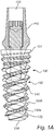
Figure 1A is a side view of an implant system comprising a dental implant according to one embodiment of the invention; -
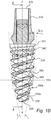
Figure 1B is a side view of an implant system comprising a dental implant according to another embodiment of the present invention; -
Figure 2 is a cross-section of the implant system in the longitudinal direction along intersection line II-II offigure 1B ; -
Figure 3A is another side view of the first embodiment of the dental implant according to the invention; -
Figure 3B is a side view of a third embodiment of a dental implant according to the invention; -
Figure 3C is another side view of the second embodiment of a dental implant according to the invention; -
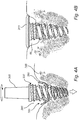
Figure 4A is an enlarged perspective view of the implantation site showing the screwing action of a dental implant according to this invention; -
Figure 4B is a perspective view of the implantation site showing the dental implant and a healing cap in its final position within the hole; -
Figure 4C is a perspective view of the implantation site after healing and installation of a dental prosthesis. -
Figure 1A shows an implant system comprising anabutment 110, anabutment screw 120, and adental implant 130 according to the invention. However, theabutment 110 and theabutment screw 120 may be replaced by any other prosthetic components of the art. - The
dental implant 130 offigure 1A substantially has a frusta-conical shape. This general shape is merely one of the preferred general shapes of the invention as will be seen below. Corresponding features in other embodiments are given corresponding last two digits in the numbering system in the drawings. In order to facilitate reading the numbering used in the present drawing is used when describing a certain feature of an embodiment. It is realized that various combinations of features or embodiments, not disclosed in detail, can be made without departing from the scope of the present invention. - The body of the
implant 130 comprises acoronal end 131 and anapical end 132. At thecoronal end 131 there is an interface for mounting prosthetic components, such as anabutment 110 and anabutment screw 120. For, example an interface to a prosthetic component as defined inUS 6,733,291 B1 ,US 2011/0020767 A1 ,US 2012/0021381 A1 ,US 8,038,442 B2 orUS 4,960,381 A may be included. - At the
apical end 132, theimplant 130 is provided with aflat tip 139. - The
dental implant 130 is provided with anexternal thread 140, starting at theapical end 132 and spiraling along the outer side of theimplant 130 toward thecoronal end 131. The thread ends on the collar or just before the collar of the implant. The thread profile of theexternal thread 140 may change along the length of theimplant 130. At theapical end 132 the thread profile may have a reduced thread depth compared to the thread profile at thecoronal end 131. In between, the thread depths gradually increase. Such thread geometry is one way to provide theimplant 130 with self-tapping property when a cutting feature such as the flute is added. - The
thread 140 shown infigure 1A is a double thread. Alternatively, one, three or four threads may be provided along the outer side ofdental implant 130. However, preferably, a double thread is used. - Two or more threads have an advantageous effect on the characteristics of the
implant 130. More specifically, by using a plurality ofthreads 140 along theimplant 130, the risk of misalignment while screwing in theimplant 130 is significantly reduced. For example, thedouble thread 140 enters the bone tissue symmetrically so that even in the beginning of insertion, the center of rotation of theimplant 130 is practically identical to thelongitudinal axis 2 of theimplant 130. Consequently, the likelihood of tilting of theimplant 130 during insertion is reduced. - Further, two or
more threads 140 also provide for a more evenly distributed loading of the bone tissue while tightening theimplant 130. For the sake of simplicity, the term pitch is used in the following for the axial distance between two crests of a single thread and the term lead is used for the distance between two crests belonging to the same thread of a double thread. In other words lead is the distance the implant propagates during one full turn during insertion. For a single threaded implant the thread pitch and lead will be equal. - An implant according to the present invention is also provided with at least two
helical cutting flutes external thread 140. As will be disclosed also in the embodiment offigure 2 the cuttingflute 150 comprises acoronal flank 151, anapical flank 153 and aflute base 152 connecting the inner edges of theapical flank 153 andcoronal flank 151. It will be appreciated that the profile of the cutting flute may be at least partly curved. Further, theflute base 152 may merge with either of thecoronal flank 151 or theapical flank 153. In another embodiment, the coronal flank may directly connect to the apical flank at a point closest to thelongitudinal axis 2. However, in all of these configurations, the apical flank 51 constitutes a cutting edge 54 and will act as a cutting flank. - Preferably, the apical flank 51 is longer than the coronal flank 53. As a result, the flute base 52 in
figure 2 is not running parallel to thelongitudinal axis 2 of said implant 30. Instead, the flute base 52 is inclined toward thecentral axis 2 in the direction of the apical end 31. - As can be seen in
figure 1A , the cutting flutes helically runs from theapical end portion 132 along the outer side ofimplant 130 toward thecoronal end 131 and preferably ends at a height so that at least one crest ofthread 140 as seen in the longitudinal cross-section along thecentral axis 2 remains. However, preferably, two crests ofthread 140 along the outer side ofimplant 130 remain in the coronal direction along central axis after tapering off of thehelical flute 150. The tapering off of the helical flute is made in order to provide an easy exit of bone debris. - Further, the two
helical flutes 150 preferably circumvents theimplant 130 at least twice and at most the number of times of the at least oneexternal thread 140. The preferred design of the flute results in a slightly steeper propagation of any flute than any thread of an embodiment according to the invention. - Although more than two flutes are achievable it has been found that an advantageous number of flutes, spiraling in the direction of the external thread(s) 140 and symmetrically distributed around the longitudinal axis, is two.
- Referring to e.g.
figures 1A and2 it is shown that the cuttingflutes 150 spiral along the outer side of the implant in the direction of theexternal thread 140 but slightly steeper. Thus, theflutes 150 intersect theexternal thread 140. This intersection with theexternal thread 140 causes theapical flank 153 to form acutting edge 154. Said cuttingedge 154 enables the external thread 40 to provide a self-tapping function to the implant. - Since cutting is performed at the
cutting edge 154 belonging to theapical flank 153, theapical flank 153 being longer than thecoronal flank 151. The space provided to collect bone debris within said flute while theimplant 130 is screwed into the bone is ideally made greater in giving the apical flank and bottom of the flute an ideal shape. In order to provide acutting edge 154 that runs along the whole cross-section of the external thread geometry, the cuttingflute 150 needs to have a greater depth than theexternal thread 140. Preferably, the flute has an at least 40% to 200% greater depth than the depth of theexternal thread 140. Consequently, the depth of theapical flank 153 has to be at least 40% deeper than the depth ofthread 140. - There exist flutes in the prior art that commonly run along a portion of the implant in its longitudinal direction. Such flutes are and have been used to passively collect bone debris resulting from the screwing operation of the implant when its thread is in contact with the bone. The
spiraling cutting flutes 150 in accordance with the present invention are designed to collect and discharge bone debris. The cutting flutes 150 spiraling along the implant also has the advantage, that the length of the cutting edge is increased in comparison to flutes known from the prior art. Such an increased length of the cutting edge provides for an even distribution of cutting forces and a more equal distribution of cut off bone tissue as well as its collection in thehelical flute 150. - According to the invention, and as seen in
figures 1A and1B , the lead of the cuttingflute external thread flute external thread implant 130 itself. More specifically, bone tissue is cut off by the cutting edge and is subsequently being positioned within theflute flute implant coronal end implant - The hole prepared for implantation of an
implant implant thread - The
implant 130 offigure 1A has a frusta-conical shape that is tapered toward itsapical end 132. Such a shape makes it possible for the flutes to continuously cut off of bone tissue along the outer side of theimplant 130. More specifically, the diameter of the implantation hole prepared prior to insertion of the implant is preferably chosen to be as small as possible allowing just about for the apical tip of the implant to enter. This allows theimplant 130 to be inserted with its tip until the thread of theimplant 130 contacts the circumferential rim of the implantation hole. In this way, the hole provides for an initial guidance of the implant into the implantation hole. - Subsequently, cutting of the bone tissue starts upon screwing the implant into the implantation hole. As will be appreciated, the conical form of the
implant 130 results in the cutting edge not only cutting the thread geometry but at the same time increasing the diameter of the prefabricated implantation hole. Thus, theimplant 130 may also act like a drill during implantation, in particular if the depth of theflute 150 is greater than the height of theexternal thread 140. - Since bone debris, resulting from expanding the hole as well as cutting the female thread in the bone, is collected in the flute 50, it will at least partly be moved toward the exit of the hole. In particular, the dental implant of the present invention may be used in patients, in which it is of advantage to use bone augmentation for providing support for soft tissue contours and an improved implant stability within the bone tissue.
- Now referring to
figure 1B , another embodiment of the implant similar to the one shown infigure 1A is disclosed. In this respect, features, advantages and effects previously described for the dental implant offigure 1A also apply to the implant offigure 1B . Further, features corresponding to features of the previous embodiment are denoted with associated reference numbers, i.e. the reference numbers have been changed by hundreds. This also applies to other embodiments described in the description. - The embodiment of the
dental implant 330 shown infigure 1B comprises acoronal section 331 and anapical section 332. Thecoronal section 331 of the implant is frusta-conical but may also be cylindrical. On the other hand, theapical section 332 of the implant is designed to be frusta-conical in order to shave off and accumulate bone tissue in the form of bone debris when screwed into e.g. an under prepared hole. The bone debris is to be subsequently used for bone augmentation, preferably in the coronal periphery ofimplant 330. Between thecoronal section 331 and the apical section 333, there is aknee 335 due to a difference in cone angles δ and γ of theapical section 332 and thecoronal section 331, respectively. As shown infigure 1B , the cone angle δ of theapical section 332 is greater than the cone angle γ of thecoronal section 331. - As a result, besides cutting the female thread into the surrounding bone tissue, the
apical section 332 also serves to increase the diameter of the implantation hole. In contrast, thecoronal section 331 is primarily intended for providing primary stability. In other words, the bone tissue is compressed in order to generate a press fit between the surface of thethread 340 and the surrounding bone tissue. This may be achieved by letting theflute 350 start to taper off after crossing theknee 335 in the coronal direction. - Preferably, the
flute 350 extends beyond the knee up to the second last thread of theexternal thread 340 as seen in the longitudinal cross-section along thecentral axis 2. - Preferably, the final geometry of the
external thread 340 is reached at the height of theknee 335. However, the width of a thread between a thread root and an adjacent thread root may well increase starting from theapical end 332 beyond theknee 335, even up to thecoronal end 331. Such a design of theexternal thread 340 additionally provides primary stability of the implant. More details concerning the geometry of such a thread may be taken from e.g. NobelActiveUS 8,038,442 B2 andUS 2012/0021381 . -
Figure 2 shows a longitudinal cross-section of implant along the line II-II shown infigure 1B . As depicted in the detail ofFigure 2 , the apical flank with thecutting edge 154 is tilted by an angle α about the normal to thelongitudinal axis 2 of the implant at the apical portion of the flute. Thus, bone tissue cut by thecutting edge 154 propagates in the direction of theflute basis 152 while bone is cut off from the circumferential wall of the implantation hole during insertion of the implant. Naturally, such a tiltedapical flank 153 is also applied to any one of the other preferred embodiments of the invention, such as the one shown infigure 1A . -
Figures 3A to 3C show different shapes applied to the dental implant. The embodiment shown infigure 3A corresponds to the embodiment shown infigure 1A . In this embodiment, the coronal as well as the apical section has the same cone angle so that thewhole implant 130 substantially has a frusta-conical shape. In contrast,implant 230 shown infigure 3B is designed to be basically cylindrical along its length. Further, the embodiment offigure 3C shows another side view of theimplant 330 offigures 1B andfigure 2 . - In the following, a procedure for implantation of an implant according to the invention will be described in more detail.
- In
figure 4A , a drill has been used to drill theimplantation hole 386.Figure 4A shows the insertion of animplant 330 according to the present invention. Naturally, any of the other embodiments described above may be used instead. Since theimplantation hole 386 is undersized compared to the diameter ofimplant 330, the coronal flank of theflute 350 cuts offbone debris 380 from the inner wall ofimplantation hole 386. As indicated by the arrow atreference sign 380, thebone debris 380 is urged along the helical flute towards the coronal end ofimplant 330 while said implant is screwed into theimplantation hole 386. As can be seen, avoid space 383 has been created and the bone debris on the sides of thehole 386 has been transported towards the coronal end ofimplant 330. The bone debris enters thevoid space 383 by exiting the flute, where theflute arrangement 350 exits or at the part of the flute extending into saidspace 383. - In
fig. 4B a following step of the procedure is shown, in which the accumulation of the bone debris stimulates bone augmentation in thespace 386 between the hole walls and acover screw 315. - Once healed,
prosthesis components 310 of any kind may be attached to the anchoredimplant 330 as disclosed infig. 4C . As can be seen atreference sign 385 infigure 4C , bone augmentation has successfully been achieved. - It will be understood by the skilled person that an implant according to the present invention may include at least one of a modified surface or a coating on at least part of its surface to enhance osseointegration. One example is the TiUnite® surface marketed by Nobel Biocare®.
- It is furthermore realized that an implant system according to the claimed invention is suitable for use during quite extensive bone healing procedures including membranes and a plurality of implants such as disclosed in e.g
US8,113,834 . The purpose of growing bone to achieve suitable positions for the implants without the risk of reduced stability and/or compromised esthetics will be achieved using implants and methods in accordance with the disclosed invention. By using the bone chips from the patient a safe and reliable one-step procedure for bone augmentation is enabled. - As described above, the present invention provides a new generation of implant that may be applied in cases with insufficient bone quality or quantity. As will be understood by the person skilled in the art, the previous embodiments are intended for explanatory purposes only, whereas the scope of protection is defined by the following independent claims. Further combinations of features defining preferred embodiments are stated in the dependent claims.
Claims (15)
- A dental implant (130; 230; 330) for promoting bone growth, comprising:an elongated implant body having a coronal end portion (131; 231; 331) and an apical end portion (132; 232; 332),
at least one external thread (140; 240; 340),a flute arrangement having a depth,
said flute arrangement having at least two helical flutes (150; 250; 350) that spiral in the general direction of said at least one external thread (140; 240; 340), wherein the helical flutes (150; 250; 350) are propagating at least one turn around the implant body, thatsaid flutes (150; 250; 350) propagating with a greater lead than said at least one thread (140; 240; 340), andsaid flute arrangement being capable of scraping off and transferring bone debris in the coronal direction of the implant during insertion. - The dental implant according to claim 1, wherein the helical flute has a greater depth into the implant body than the thread (140; 240; 340), preferably 40% to 200%, more preferably 60% to 150%.
- The dental implant according to any one of the preceding claims, wherein the thread (140; 240; 340) extends beyond the flute arrangement (150; 250; 350) in the coronal direction.
- The dental implant according to any one of the preceding claims, wherein the flute has a coronal flank (151) and an apical flank (153), wherein the apical flank provides a cutting edge (154).
- The dental implant according to claim 4, wherein an angle (α) as measured in the longitudinal cross section of the implant (130; 230; 330) between the apical flank (153) and a normal to the longitudinal axis (102; 202; 302) of said implant is between 0° and 5°, preferably between 1° and 3°.
- The dental implant according to claim 4 or 5, further comprising a flute base (52; 152) between the coronal flank (151 ; 251 ; 351) and the apical flank (153; 253; 353) of the flute arrangement (150; 250; 350), the flute base, as measured in the longitudinal cross section of the implant (130; 230; 330), preferably being inclined toward the longitudinal axis in the direction of the apical end (131; 231; 331).
- The dental implant according to any one of the preceding claims, wherein the diameter of said implant is greater in the coronal region than in the more apical region.
- The dental implant according to any one of the preceding claims, wherein the implant includes a coronal section (133; 333) and an apical section (134; 334), the coronal section and the apical section separated by a knee (135; 335), wherein at least the apical section is tapered toward the apical end portion (132; 332).
- The dental implant according to claim 8, wherein a cone angle (γ) of the coronal section (133; 333) is less than a cone angle (δ) of the apical section (134; 334).
- The dental implant according to claim 8 or 9, wherein the external thread (140; 340) starts at the apical end portion (132; 332) and has its greatest height from the implant body at the knee (135; 335).
- The dental implant according to any one of the preceding claims, wherein a width of a thread flank between a thread root and an adjacent thread root increases toward the coronal end (131; 231; 331).
- Dental implant according to any one of the preceding claims, wherein the implant (130; 230; 330) comprises a prosthetic interface at its coronal end (131; 231; 331).
- Dental implant according to any one of the preceding claims, wherein at least one of the external thread (140; 240; 340) and the flute (150; 250; 350) comprises at least one groove (141).
- Implant system, comprising:
a dental implant (30; 130; 230; 330; 430) according to any one of the previous claims, and at least one prosthesis (90). - Implant system according to claim 14, wherein the prosthesis (90) comprises at least one of an abutment (10; 110), an abutment screw (20; 120), a bridge, a bar and a prosthetic tooth.
Applications Claiming Priority (2)
| Application Number | Priority Date | Filing Date | Title |
|---|---|---|---|
| GB1404049.7A GB2523828A (en) | 2014-03-07 | 2014-03-07 | Dental implant |
| PCT/EP2015/054570 WO2015132323A1 (en) | 2014-03-07 | 2015-03-05 | Dental implant |
Publications (2)
| Publication Number | Publication Date |
|---|---|
| EP3113717A1 EP3113717A1 (en) | 2017-01-11 |
| EP3113717B1 true EP3113717B1 (en) | 2020-09-02 |
Family
ID=50554689
Family Applications (1)
| Application Number | Title | Priority Date | Filing Date |
|---|---|---|---|
| EP15710139.5A Revoked EP3113717B1 (en) | 2014-03-07 | 2015-03-05 | Dental implant |
Country Status (11)
| Country | Link |
|---|---|
| US (1) | US10603140B2 (en) |
| EP (1) | EP3113717B1 (en) |
| JP (1) | JP6682444B2 (en) |
| KR (1) | KR102384540B1 (en) |
| CN (1) | CN106102649B (en) |
| AU (1) | AU2015226158B2 (en) |
| BR (1) | BR112016020573B1 (en) |
| CA (1) | CA2941483C (en) |
| ES (1) | ES2832349T3 (en) |
| GB (1) | GB2523828A (en) |
| WO (1) | WO2015132323A1 (en) |
Families Citing this family (14)
| Publication number | Priority date | Publication date | Assignee | Title |
|---|---|---|---|---|
| US10245128B2 (en) | 2016-09-01 | 2019-04-02 | National Guard Health Affairs | Damping dental root post key |
| CN106691543A (en) * | 2017-02-21 | 2017-05-24 | 江苏水木天蓬科技有限公司 | Ultrasonic scalpel head |
| EP3398553A1 (en) | 2017-05-02 | 2018-11-07 | Ophir Fromovich | Improved dental implant system |
| IT201700068034A1 (en) * | 2017-06-19 | 2018-12-19 | Plan 1 Health Srl | ENDOSSEO DENTAL PLANT |
| US11382724B2 (en) | 2017-10-11 | 2022-07-12 | Evollution Ip Holdings, Inc. | Three-dimensional stabilization thread form for dental implants |
| CN112334080B (en) | 2018-06-13 | 2024-08-16 | 史赛克欧洲运营有限公司 | Bone fragments collecting device and processing device |
| CN109938855A (en) * | 2019-04-09 | 2019-06-28 | 江苏创英医疗器械有限公司 | A kind of dental implant with variable diameter screw thread |
| US11266874B2 (en) * | 2019-05-01 | 2022-03-08 | Michael Spink | Jaw range of motion device |
| EP3763321B1 (en) * | 2019-07-08 | 2021-10-20 | Anthogyr | Dental implant with improved thread |
| ES2899627T3 (en) * | 2019-07-08 | 2022-03-14 | Anthogyr Sa | Improved self-tapping dental implant |
| US12274629B2 (en) | 2019-12-18 | 2025-04-15 | Stryker European Operations Limited | Bone fragment collector and processor |
| EP4590231A1 (en) | 2022-09-22 | 2025-07-30 | Institut Straumann AG | Dental implant |
| EP4676387A2 (en) * | 2023-03-09 | 2026-01-14 | Huwais IP Holding LLC | Bone conditioning implant |
| CN116807653A (en) * | 2023-07-03 | 2023-09-29 | 深圳大洲医学科技有限公司 | Dental implant |
Citations (10)
| Publication number | Priority date | Publication date | Assignee | Title |
|---|---|---|---|---|
| RO110899B1 (en) | 1995-03-20 | 1996-05-30 | Deac Valeriu | Ostheointegrated implant for fixed, protected action |
| US5897319A (en) | 1997-09-12 | 1999-04-27 | Sulzer Calcitek Inc. | Self-tapping implant with helical flutes |
| US6135772A (en) | 1994-08-15 | 2000-10-24 | Jones; Shedrick D. | Method and apparatus for implantation |
| US6382976B1 (en) | 2001-02-05 | 2002-05-07 | Sulzer Dental Inc. | Dental implant having round bottom with fluid directing channels |
| US20080227057A1 (en) | 2005-02-08 | 2008-09-18 | Biotechnology Institute.I Mas D. S.L. | Narrow Dental Implant and Associated Parts |
| US20080261175A1 (en) | 2007-04-23 | 2008-10-23 | Nobel Biocare Services Ag | Dental implant |
| US20100009316A1 (en) | 2008-07-14 | 2010-01-14 | Hurson Steven M | Compact dental implant |
| US8038442B2 (en) | 2007-04-23 | 2011-10-18 | Nobel Biocare Services Ag | Dental implant and dental component connection |
| US20110294094A1 (en) | 2010-06-01 | 2011-12-01 | Mark Moshavi | Implant and method |
| CN102697570A (en) | 2012-06-15 | 2012-10-03 | 西北有色金属研究院 | Dental implant |
Family Cites Families (69)
| Publication number | Priority date | Publication date | Assignee | Title |
|---|---|---|---|---|
| US4697969A (en) | 1985-09-06 | 1987-10-06 | Sparkes Wilford S | Wood screw |
| CH673086A5 (en) | 1987-09-08 | 1990-02-15 | Maillefer Auguste Sa | |
| US6604945B1 (en) | 1994-08-15 | 2003-08-12 | Shedrick D. Jones | Method and apparatus for implantation |
| US5628630A (en) | 1994-12-15 | 1997-05-13 | Univ. Of Alabama At Birmingham | Design process for skeletal implants to optimize cellular response |
| US5601429A (en) * | 1995-08-11 | 1997-02-11 | Blacklock; Gordon D. | Dental implant anchor |
| JP3050789B2 (en) | 1996-01-08 | 2000-06-12 | 株式会社青山製作所 | Tapping screw |
| JP3881025B2 (en) | 1996-01-18 | 2007-02-14 | インプラント・イノヴェーションズ・インコーポレーテッド | Low friction screw dental implant |
| GB2313167B (en) | 1996-05-15 | 2000-05-10 | Chen Sen Yang | Screw for fibrous boards |
| EP1430843B1 (en) * | 1996-08-26 | 2007-10-17 | Shedrick D. Jones | Drill apparatus for embedding an implant in bone |
| SE9701647D0 (en) | 1997-04-30 | 1997-04-30 | Nobel Biocare Ab | Calcium-phonsphate coated implant element |
| SE516917C2 (en) | 1997-11-11 | 2002-03-19 | Nobel Biocare Ab | Device for providing reliable anchoring of threaded implants in bone |
| SE513556C2 (en) | 1997-11-11 | 2000-10-02 | Nobel Biocare Ab | Implant element with thin surface applied by hot isostatic pressing |
| SE9802571D0 (en) * | 1998-07-17 | 1998-07-17 | Astra Ab | Implant |
| KR20000074878A (en) * | 1999-05-26 | 2000-12-15 | 임윤배 | A mat process |
| SE514323C2 (en) | 1999-05-31 | 2001-02-12 | Nobel Biocare Ab | Implants and procedure and use in implants |
| SE514342C2 (en) | 1999-05-31 | 2001-02-12 | Nobel Biocare Ab | Method, apparatus and use in implants to ensure delivery of bioactive substance to the surrounding bone and / or tissue of the implant |
| SE514202C2 (en) | 1999-05-31 | 2001-01-22 | Nobel Biocare Ab | Layers arranged on bone or tissue structure implants and such implants and methods for applying the layer |
| SE515695C2 (en) | 1999-05-31 | 2001-09-24 | Nobel Biocare Ab | Implant with coating of bone growth stimulant for bone application and procedure in such implant |
| US6273722B1 (en) | 1999-11-29 | 2001-08-14 | Swiss Implants, Inc. | Hybrid press fit-threaded dental implant |
| US6679701B1 (en) | 2000-03-23 | 2004-01-20 | Gordon D. Blacklock | Anchor having threads opposing unthreading |
| US7048541B2 (en) | 2000-04-04 | 2006-05-23 | Nobel Biocare Ab | Implant having attachment and hole-insert parts, and method for producing such an implant |
| SE516282C2 (en) | 2000-04-04 | 2001-12-10 | Nobel Biocare Ab | Implants provided with connection and hole insertion parts and the procedure for such implants |
| TW551440U (en) | 2000-05-30 | 2003-09-01 | Tai-Ping Shiu | Structure for wood screw |
| US6402515B1 (en) | 2001-01-10 | 2002-06-11 | Sulzer Dental Inc. | Dental implant with variable profile thread |
| US6527554B2 (en) | 2001-06-04 | 2003-03-04 | Nobel Biocare Ab | Natural implant system |
| SE519566C2 (en) | 2001-07-04 | 2003-03-11 | Nobel Biocare Ab | Method of Treating Implants by Coating with Calcium Phosphate and Bone Growth Stimulants |
| SE519564C2 (en) | 2001-07-04 | 2003-03-11 | Nobel Biocare Ab | Implants, for example dental implants, coated with bone growth stimulants |
| SE523395C2 (en) | 2001-12-21 | 2004-04-13 | Nobel Biocare Ab | Implants and methods and systems for providing such implants |
| SE520756C2 (en) | 2001-12-21 | 2003-08-19 | Nobel Biocare Ab | Method of providing surface structure on implants as well as such implants |
| US7033174B2 (en) | 2002-06-07 | 2006-04-25 | Thierry Giorno | Prosthetic mounting device |
| KR100430770B1 (en) | 2002-06-27 | 2004-05-17 | 박영철 | Implant |
| SE522501C2 (en) | 2002-06-27 | 2004-02-10 | Nobel Biocare Ab | Preferably completely spaced ceramic spacer with adapter |
| SE523024C2 (en) | 2002-07-25 | 2004-03-23 | Nobel Biocare Ab | Device for inducing bone by bone inductive or bioactive agent and / or increasing the stability of jaw bone implants and implants therefor |
| SE522984C2 (en) | 2002-07-25 | 2004-03-23 | Nobel Biocare Ab | Device for two or more implants provided with growth-stimulating substance (s) |
| SE522983C2 (en) | 2002-07-25 | 2004-03-23 | Nobel Biocare Ab | Arrangements to increase the resistance to load on implants and such implants |
| US7008226B2 (en) | 2002-08-23 | 2006-03-07 | Woodwelding Ag | Implant, in particular a dental implant |
| US6997711B2 (en) | 2002-12-23 | 2006-02-14 | Robert Jeffrey Miller | Dental implant |
| SE526667C2 (en) * | 2002-12-30 | 2005-10-25 | Nobel Biocare Ab | Device for implants and method for making the implant |
| DE10319781B3 (en) | 2003-04-30 | 2004-08-26 | Biedermann Motech Gmbh | Bone anchor, to attach a component to the bone, has a head to hold the component and a shaft with screw thread sections and thread-free sections along the shaft length |
| IL156033A0 (en) | 2003-05-21 | 2004-03-28 | Ophir Fromovich Ophir Fromovic | Dental implant |
| DE10350424B4 (en) | 2003-10-29 | 2006-03-30 | Ulrich Gmbh & Co. Kg | bone screw |
| US20070083168A1 (en) * | 2004-09-30 | 2007-04-12 | Whiting James S | Transmembrane access systems and methods |
| DE102006013456A1 (en) | 2006-03-23 | 2007-09-27 | Gebr. Brasseler Gmbh & Co. Kg | Dental implant |
| US20090130631A1 (en) * | 2006-11-30 | 2009-05-21 | Chun-Leon Chen | Implant root for tooth implanting |
| US20090258328A1 (en) | 2006-11-30 | 2009-10-15 | Chun-Leon Chen | 5 in 1 dental implant method and apparatus |
| EP2095790A1 (en) | 2008-02-28 | 2009-09-02 | Eugenio Gastaldi | Bio-compatible device for dental bone implantation for anatomical restoration |
| EP2145600A1 (en) * | 2008-07-14 | 2010-01-20 | Nobel Biocare Services AG | Improved fixture of two-piece dental implants |
| US8052422B2 (en) | 2008-08-29 | 2011-11-08 | Hung William Y S | Dental implant |
| ES2687256T3 (en) | 2009-01-27 | 2018-10-24 | Intra-Lock International Inc. | Self-tapping implant |
| US20130273500A1 (en) | 2009-02-02 | 2013-10-17 | Thierry Giorno | Dental Implant and Method for Rapid Integration |
| EP2233108B1 (en) | 2009-03-23 | 2015-04-29 | Dentsply IH AB | Bone fixture |
| IL201115A0 (en) * | 2009-09-23 | 2010-06-16 | Elkana Elyav Dr | Dental implant |
| IL201902A (en) * | 2009-11-03 | 2012-12-31 | Ben-Zion Karmon | Dental implant |
| TWM390130U (en) * | 2010-04-15 | 2010-10-11 | jun-long Chen | One piece angle implant |
| TWM390132U (en) | 2010-04-15 | 2010-10-11 | jun-long Chen | Abutment extender for one piece implant |
| TWM392650U (en) | 2010-06-04 | 2010-11-21 | jun-long Chen | Repairable single-piece dental implant body |
| US20120015325A1 (en) | 2010-07-13 | 2012-01-19 | Chun-Leon Chen | Restorable one piece implant |
| US8986007B2 (en) * | 2010-07-13 | 2015-03-24 | Star Generation Limited | Restorable zirconium dioxide-based one piece dental implant |
| US20130022942A1 (en) * | 2011-07-20 | 2013-01-24 | Zadeh Parsa T | Self-osteotomizing and grafting bone implant |
| US20130045462A1 (en) * | 2011-08-17 | 2013-02-21 | Yu-Hong Tzeng | Dental implant fixing system |
| KR101276418B1 (en) * | 2012-04-19 | 2013-06-18 | 황정빈 | Tooth implant |
| EP2656813A1 (en) | 2012-04-26 | 2013-10-30 | Chun-Leon Chen | Restorable zirconium dioxide-based one piece dental implant |
| WO2014015283A1 (en) | 2012-07-19 | 2014-01-23 | Zadeh Parsa T | Self-osteotomizing bone implant and related method |
| US20140045144A1 (en) | 2012-08-07 | 2014-02-13 | Mazen Dukhan | Dental Implant and Method of Implantation |
| ES2818910T3 (en) * | 2012-08-13 | 2021-04-14 | Camlog Biotechnologies Gmbh | Secondary part, kit and packaging for a dental implant system |
| CN103271774A (en) | 2013-06-07 | 2013-09-04 | 大连三生科技发展有限公司 | Micro screw implant |
| US11240613B2 (en) * | 2014-01-30 | 2022-02-01 | Cochlear Limited | Bone conduction implant |
| IL230833A0 (en) | 2014-02-05 | 2014-09-30 | Ophir Fromovich | Bone implant anchor |
| WO2015125139A2 (en) | 2014-02-20 | 2015-08-27 | MIS Implants Technologies Ltd. | Dental implant |
-
2014
- 2014-03-07 GB GB1404049.7A patent/GB2523828A/en not_active Withdrawn
-
2015
- 2015-03-05 BR BR112016020573-1A patent/BR112016020573B1/en active IP Right Grant
- 2015-03-05 US US15/123,542 patent/US10603140B2/en active Active
- 2015-03-05 CN CN201580012278.3A patent/CN106102649B/en active Active
- 2015-03-05 WO PCT/EP2015/054570 patent/WO2015132323A1/en not_active Ceased
- 2015-03-05 JP JP2016551150A patent/JP6682444B2/en active Active
- 2015-03-05 CA CA2941483A patent/CA2941483C/en active Active
- 2015-03-05 AU AU2015226158A patent/AU2015226158B2/en active Active
- 2015-03-05 ES ES15710139T patent/ES2832349T3/en active Active
- 2015-03-05 EP EP15710139.5A patent/EP3113717B1/en not_active Revoked
- 2015-03-05 KR KR1020167027832A patent/KR102384540B1/en active Active
Patent Citations (10)
| Publication number | Priority date | Publication date | Assignee | Title |
|---|---|---|---|---|
| US6135772A (en) | 1994-08-15 | 2000-10-24 | Jones; Shedrick D. | Method and apparatus for implantation |
| RO110899B1 (en) | 1995-03-20 | 1996-05-30 | Deac Valeriu | Ostheointegrated implant for fixed, protected action |
| US5897319A (en) | 1997-09-12 | 1999-04-27 | Sulzer Calcitek Inc. | Self-tapping implant with helical flutes |
| US6382976B1 (en) | 2001-02-05 | 2002-05-07 | Sulzer Dental Inc. | Dental implant having round bottom with fluid directing channels |
| US20080227057A1 (en) | 2005-02-08 | 2008-09-18 | Biotechnology Institute.I Mas D. S.L. | Narrow Dental Implant and Associated Parts |
| US20080261175A1 (en) | 2007-04-23 | 2008-10-23 | Nobel Biocare Services Ag | Dental implant |
| US8038442B2 (en) | 2007-04-23 | 2011-10-18 | Nobel Biocare Services Ag | Dental implant and dental component connection |
| US20100009316A1 (en) | 2008-07-14 | 2010-01-14 | Hurson Steven M | Compact dental implant |
| US20110294094A1 (en) | 2010-06-01 | 2011-12-01 | Mark Moshavi | Implant and method |
| CN102697570A (en) | 2012-06-15 | 2012-10-03 | 西北有色金属研究院 | Dental implant |
Also Published As
| Publication number | Publication date |
|---|---|
| BR112016020573A2 (en) | 2017-08-15 |
| CN106102649B (en) | 2019-12-06 |
| US10603140B2 (en) | 2020-03-31 |
| GB2523828A (en) | 2015-09-09 |
| WO2015132323A1 (en) | 2015-09-11 |
| CN106102649A (en) | 2016-11-09 |
| JP2017506950A (en) | 2017-03-16 |
| US20170065377A1 (en) | 2017-03-09 |
| CA2941483A1 (en) | 2015-09-11 |
| AU2015226158A1 (en) | 2016-08-18 |
| CA2941483C (en) | 2022-08-16 |
| JP6682444B2 (en) | 2020-04-15 |
| ES2832349T3 (en) | 2021-06-10 |
| KR20160126082A (en) | 2016-11-01 |
| AU2015226158B2 (en) | 2017-02-23 |
| EP3113717A1 (en) | 2017-01-11 |
| BR112016020573B1 (en) | 2021-07-27 |
| GB201404049D0 (en) | 2014-04-23 |
| KR102384540B1 (en) | 2022-04-08 |
Similar Documents
| Publication | Publication Date | Title |
|---|---|---|
| US10603140B2 (en) | Dental implant | |
| EP3113716B1 (en) | Dental implant | |
| KR101139962B1 (en) | Dental implant having plate | |
| CN102316819A (en) | Dental implant | |
| EP2510898A1 (en) | Fixture | |
| EP3391850B1 (en) | Fixture element | |
| KR200456270Y1 (en) | Fixture for implant | |
| EP2301475B1 (en) | Dental implant | |
| CN103476356B (en) | Holder | |
| WO2013186765A1 (en) | Modular dental implant | |
| EP3291759B1 (en) | Dental implant | |
| US10849720B2 (en) | Dental implant and dental implant system | |
| EP2623064B1 (en) | Implant for expanding the jawbone crest | |
| WO2020242979A1 (en) | Dental implant system |
Legal Events
| Date | Code | Title | Description |
|---|---|---|---|
| STAA | Information on the status of an ep patent application or granted ep patent |
Free format text: STATUS: THE INTERNATIONAL PUBLICATION HAS BEEN MADE |
|
| PUAI | Public reference made under article 153(3) epc to a published international application that has entered the european phase |
Free format text: ORIGINAL CODE: 0009012 |
|
| STAA | Information on the status of an ep patent application or granted ep patent |
Free format text: STATUS: REQUEST FOR EXAMINATION WAS MADE |
|
| 17P | Request for examination filed |
Effective date: 20161007 |
|
| AK | Designated contracting states |
Kind code of ref document: A1 Designated state(s): AL AT BE BG CH CY CZ DE DK EE ES FI FR GB GR HR HU IE IS IT LI LT LU LV MC MK MT NL NO PL PT RO RS SE SI SK SM TR |
|
| AX | Request for extension of the european patent |
Extension state: BA ME |
|
| DAV | Request for validation of the european patent (deleted) | ||
| DAX | Request for extension of the european patent (deleted) | ||
| STAA | Information on the status of an ep patent application or granted ep patent |
Free format text: STATUS: EXAMINATION IS IN PROGRESS |
|
| 17Q | First examination report despatched |
Effective date: 20181119 |
|
| GRAP | Despatch of communication of intention to grant a patent |
Free format text: ORIGINAL CODE: EPIDOSNIGR1 |
|
| STAA | Information on the status of an ep patent application or granted ep patent |
Free format text: STATUS: GRANT OF PATENT IS INTENDED |
|
| INTG | Intention to grant announced |
Effective date: 20200326 |
|
| GRAS | Grant fee paid |
Free format text: ORIGINAL CODE: EPIDOSNIGR3 |
|
| GRAA | (expected) grant |
Free format text: ORIGINAL CODE: 0009210 |
|
| STAA | Information on the status of an ep patent application or granted ep patent |
Free format text: STATUS: THE PATENT HAS BEEN GRANTED |
|
| AK | Designated contracting states |
Kind code of ref document: B1 Designated state(s): AL AT BE BG CH CY CZ DE DK EE ES FI FR GB GR HR HU IE IS IT LI LT LU LV MC MK MT NL NO PL PT RO RS SE SI SK SM TR |
|
| REG | Reference to a national code |
Ref country code: GB Ref legal event code: FG4D |
|
| REG | Reference to a national code |
Ref country code: AT Ref legal event code: REF Ref document number: 1307910 Country of ref document: AT Kind code of ref document: T Effective date: 20200915 Ref country code: CH Ref legal event code: EP |
|
| REG | Reference to a national code |
Ref country code: DE Ref legal event code: R096 Ref document number: 602015058320 Country of ref document: DE |
|
| REG | Reference to a national code |
Ref country code: IE Ref legal event code: FG4D |
|
| REG | Reference to a national code |
Ref country code: NL Ref legal event code: FP |
|
| REG | Reference to a national code |
Ref country code: SE Ref legal event code: TRGR |
|
| REG | Reference to a national code |
Ref country code: LT Ref legal event code: MG4D |
|
| PG25 | Lapsed in a contracting state [announced via postgrant information from national office to epo] |
Ref country code: FI Free format text: LAPSE BECAUSE OF FAILURE TO SUBMIT A TRANSLATION OF THE DESCRIPTION OR TO PAY THE FEE WITHIN THE PRESCRIBED TIME-LIMIT Effective date: 20200902 Ref country code: HR Free format text: LAPSE BECAUSE OF FAILURE TO SUBMIT A TRANSLATION OF THE DESCRIPTION OR TO PAY THE FEE WITHIN THE PRESCRIBED TIME-LIMIT Effective date: 20200902 Ref country code: LT Free format text: LAPSE BECAUSE OF FAILURE TO SUBMIT A TRANSLATION OF THE DESCRIPTION OR TO PAY THE FEE WITHIN THE PRESCRIBED TIME-LIMIT Effective date: 20200902 Ref country code: BG Free format text: LAPSE BECAUSE OF FAILURE TO SUBMIT A TRANSLATION OF THE DESCRIPTION OR TO PAY THE FEE WITHIN THE PRESCRIBED TIME-LIMIT Effective date: 20201202 Ref country code: GR Free format text: LAPSE BECAUSE OF FAILURE TO SUBMIT A TRANSLATION OF THE DESCRIPTION OR TO PAY THE FEE WITHIN THE PRESCRIBED TIME-LIMIT Effective date: 20201203 Ref country code: NO Free format text: LAPSE BECAUSE OF FAILURE TO SUBMIT A TRANSLATION OF THE DESCRIPTION OR TO PAY THE FEE WITHIN THE PRESCRIBED TIME-LIMIT Effective date: 20201202 |
|
| REG | Reference to a national code |
Ref country code: AT Ref legal event code: MK05 Ref document number: 1307910 Country of ref document: AT Kind code of ref document: T Effective date: 20200902 |
|
| PG25 | Lapsed in a contracting state [announced via postgrant information from national office to epo] |
Ref country code: PL Free format text: LAPSE BECAUSE OF FAILURE TO SUBMIT A TRANSLATION OF THE DESCRIPTION OR TO PAY THE FEE WITHIN THE PRESCRIBED TIME-LIMIT Effective date: 20200902 Ref country code: LV Free format text: LAPSE BECAUSE OF FAILURE TO SUBMIT A TRANSLATION OF THE DESCRIPTION OR TO PAY THE FEE WITHIN THE PRESCRIBED TIME-LIMIT Effective date: 20200902 Ref country code: RS Free format text: LAPSE BECAUSE OF FAILURE TO SUBMIT A TRANSLATION OF THE DESCRIPTION OR TO PAY THE FEE WITHIN THE PRESCRIBED TIME-LIMIT Effective date: 20200902 |
|
| PG25 | Lapsed in a contracting state [announced via postgrant information from national office to epo] |
Ref country code: PT Free format text: LAPSE BECAUSE OF FAILURE TO SUBMIT A TRANSLATION OF THE DESCRIPTION OR TO PAY THE FEE WITHIN THE PRESCRIBED TIME-LIMIT Effective date: 20210104 Ref country code: SM Free format text: LAPSE BECAUSE OF FAILURE TO SUBMIT A TRANSLATION OF THE DESCRIPTION OR TO PAY THE FEE WITHIN THE PRESCRIBED TIME-LIMIT Effective date: 20200902 Ref country code: RO Free format text: LAPSE BECAUSE OF FAILURE TO SUBMIT A TRANSLATION OF THE DESCRIPTION OR TO PAY THE FEE WITHIN THE PRESCRIBED TIME-LIMIT Effective date: 20200902 Ref country code: EE Free format text: LAPSE BECAUSE OF FAILURE TO SUBMIT A TRANSLATION OF THE DESCRIPTION OR TO PAY THE FEE WITHIN THE PRESCRIBED TIME-LIMIT Effective date: 20200902 Ref country code: CZ Free format text: LAPSE BECAUSE OF FAILURE TO SUBMIT A TRANSLATION OF THE DESCRIPTION OR TO PAY THE FEE WITHIN THE PRESCRIBED TIME-LIMIT Effective date: 20200902 |
|
| PG25 | Lapsed in a contracting state [announced via postgrant information from national office to epo] |
Ref country code: IS Free format text: LAPSE BECAUSE OF FAILURE TO SUBMIT A TRANSLATION OF THE DESCRIPTION OR TO PAY THE FEE WITHIN THE PRESCRIBED TIME-LIMIT Effective date: 20210102 Ref country code: AL Free format text: LAPSE BECAUSE OF FAILURE TO SUBMIT A TRANSLATION OF THE DESCRIPTION OR TO PAY THE FEE WITHIN THE PRESCRIBED TIME-LIMIT Effective date: 20200902 Ref country code: AT Free format text: LAPSE BECAUSE OF FAILURE TO SUBMIT A TRANSLATION OF THE DESCRIPTION OR TO PAY THE FEE WITHIN THE PRESCRIBED TIME-LIMIT Effective date: 20200902 |
|
| REG | Reference to a national code |
Ref country code: DE Ref legal event code: R026 Ref document number: 602015058320 Country of ref document: DE |
|
| REG | Reference to a national code |
Ref country code: ES Ref legal event code: FG2A Ref document number: 2832349 Country of ref document: ES Kind code of ref document: T3 Effective date: 20210610 |
|
| PLBI | Opposition filed |
Free format text: ORIGINAL CODE: 0009260 |
|
| PLAX | Notice of opposition and request to file observation + time limit sent |
Free format text: ORIGINAL CODE: EPIDOSNOBS2 |
|
| PG25 | Lapsed in a contracting state [announced via postgrant information from national office to epo] |
Ref country code: SK Free format text: LAPSE BECAUSE OF FAILURE TO SUBMIT A TRANSLATION OF THE DESCRIPTION OR TO PAY THE FEE WITHIN THE PRESCRIBED TIME-LIMIT Effective date: 20200902 |
|
| 26 | Opposition filed |
Opponent name: INSTITUT STRAUMANN AG Effective date: 20210602 |
|
| PG25 | Lapsed in a contracting state [announced via postgrant information from national office to epo] |
Ref country code: DK Free format text: LAPSE BECAUSE OF FAILURE TO SUBMIT A TRANSLATION OF THE DESCRIPTION OR TO PAY THE FEE WITHIN THE PRESCRIBED TIME-LIMIT Effective date: 20200902 Ref country code: SI Free format text: LAPSE BECAUSE OF FAILURE TO SUBMIT A TRANSLATION OF THE DESCRIPTION OR TO PAY THE FEE WITHIN THE PRESCRIBED TIME-LIMIT Effective date: 20200902 |
|
| PLBB | Reply of patent proprietor to notice(s) of opposition received |
Free format text: ORIGINAL CODE: EPIDOSNOBS3 |
|
| PG25 | Lapsed in a contracting state [announced via postgrant information from national office to epo] |
Ref country code: MC Free format text: LAPSE BECAUSE OF FAILURE TO SUBMIT A TRANSLATION OF THE DESCRIPTION OR TO PAY THE FEE WITHIN THE PRESCRIBED TIME-LIMIT Effective date: 20200902 |
|
| REG | Reference to a national code |
Ref country code: BE Ref legal event code: MM Effective date: 20210331 |
|
| PG25 | Lapsed in a contracting state [announced via postgrant information from national office to epo] |
Ref country code: IE Free format text: LAPSE BECAUSE OF NON-PAYMENT OF DUE FEES Effective date: 20210305 Ref country code: LU Free format text: LAPSE BECAUSE OF NON-PAYMENT OF DUE FEES Effective date: 20210305 |
|
| PG25 | Lapsed in a contracting state [announced via postgrant information from national office to epo] |
Ref country code: BE Free format text: LAPSE BECAUSE OF NON-PAYMENT OF DUE FEES Effective date: 20210331 |
|
| PLCK | Communication despatched that opposition was rejected |
Free format text: ORIGINAL CODE: EPIDOSNREJ1 |
|
| APBM | Appeal reference recorded |
Free format text: ORIGINAL CODE: EPIDOSNREFNO |
|
| APBP | Date of receipt of notice of appeal recorded |
Free format text: ORIGINAL CODE: EPIDOSNNOA2O |
|
| APAH | Appeal reference modified |
Free format text: ORIGINAL CODE: EPIDOSCREFNO |
|
| APBQ | Date of receipt of statement of grounds of appeal recorded |
Free format text: ORIGINAL CODE: EPIDOSNNOA3O |
|
| PG25 | Lapsed in a contracting state [announced via postgrant information from national office to epo] |
Ref country code: HU Free format text: LAPSE BECAUSE OF FAILURE TO SUBMIT A TRANSLATION OF THE DESCRIPTION OR TO PAY THE FEE WITHIN THE PRESCRIBED TIME-LIMIT; INVALID AB INITIO Effective date: 20150305 |
|
| PG25 | Lapsed in a contracting state [announced via postgrant information from national office to epo] |
Ref country code: CY Free format text: LAPSE BECAUSE OF FAILURE TO SUBMIT A TRANSLATION OF THE DESCRIPTION OR TO PAY THE FEE WITHIN THE PRESCRIBED TIME-LIMIT Effective date: 20200902 |
|
| P01 | Opt-out of the competence of the unified patent court (upc) registered |
Effective date: 20230601 |
|
| PG25 | Lapsed in a contracting state [announced via postgrant information from national office to epo] |
Ref country code: MK Free format text: LAPSE BECAUSE OF FAILURE TO SUBMIT A TRANSLATION OF THE DESCRIPTION OR TO PAY THE FEE WITHIN THE PRESCRIBED TIME-LIMIT Effective date: 20200902 |
|
| PGFP | Annual fee paid to national office [announced via postgrant information from national office to epo] |
Ref country code: DE Payment date: 20231229 Year of fee payment: 10 |
|
| PGFP | Annual fee paid to national office [announced via postgrant information from national office to epo] |
Ref country code: IT Payment date: 20240212 Year of fee payment: 10 |
|
| PG25 | Lapsed in a contracting state [announced via postgrant information from national office to epo] |
Ref country code: TR Free format text: LAPSE BECAUSE OF FAILURE TO SUBMIT A TRANSLATION OF THE DESCRIPTION OR TO PAY THE FEE WITHIN THE PRESCRIBED TIME-LIMIT Effective date: 20200902 |
|
| PGFP | Annual fee paid to national office [announced via postgrant information from national office to epo] |
Ref country code: CH Payment date: 20240401 Year of fee payment: 10 |
|
| PGFP | Annual fee paid to national office [announced via postgrant information from national office to epo] |
Ref country code: ES Payment date: 20240409 Year of fee payment: 10 |
|
| PG25 | Lapsed in a contracting state [announced via postgrant information from national office to epo] |
Ref country code: MT Free format text: LAPSE BECAUSE OF FAILURE TO SUBMIT A TRANSLATION OF THE DESCRIPTION OR TO PAY THE FEE WITHIN THE PRESCRIBED TIME-LIMIT Effective date: 20200902 |
|
| REG | Reference to a national code |
Ref country code: DE Ref legal event code: R103 Ref document number: 602015058320 Country of ref document: DE Ref country code: DE Ref legal event code: R064 Ref document number: 602015058320 Country of ref document: DE |
|
| APBU | Appeal procedure closed |
Free format text: ORIGINAL CODE: EPIDOSNNOA9O |
|
| PGFP | Annual fee paid to national office [announced via postgrant information from national office to epo] |
Ref country code: FR Payment date: 20241231 Year of fee payment: 11 |
|
| PGFP | Annual fee paid to national office [announced via postgrant information from national office to epo] |
Ref country code: NL Payment date: 20250107 Year of fee payment: 11 |
|
| RDAF | Communication despatched that patent is revoked |
Free format text: ORIGINAL CODE: EPIDOSNREV1 |
|
| STAA | Information on the status of an ep patent application or granted ep patent |
Free format text: STATUS: PATENT REVOKED |
|
| RDAG | Patent revoked |
Free format text: ORIGINAL CODE: 0009271 |
|
| REG | Reference to a national code |
Ref country code: CH Ref legal event code: PL |
|
| 27W | Patent revoked |
Effective date: 20250109 |
|
| GBPR | Gb: patent revoked under art. 102 of the ep convention designating the uk as contracting state |
Effective date: 20250109 |
|
| PGFP | Annual fee paid to national office [announced via postgrant information from national office to epo] |
Ref country code: SE Payment date: 20250103 Year of fee payment: 11 |
|
| PGFP | Annual fee paid to national office [announced via postgrant information from national office to epo] |
Ref country code: GB Payment date: 20250102 Year of fee payment: 11 |
|
| REG | Reference to a national code |
Ref country code: SE Ref legal event code: ECNC |