EP3113576A1 - Tray for cooking food and process for manufacturing a tray - Google Patents
Tray for cooking food and process for manufacturing a tray Download PDFInfo
- Publication number
- EP3113576A1 EP3113576A1 EP15174966.0A EP15174966A EP3113576A1 EP 3113576 A1 EP3113576 A1 EP 3113576A1 EP 15174966 A EP15174966 A EP 15174966A EP 3113576 A1 EP3113576 A1 EP 3113576A1
- Authority
- EP
- European Patent Office
- Prior art keywords
- tray
- base plate
- side wall
- plate
- openings
- Prior art date
- Legal status (The legal status is an assumption and is not a legal conclusion. Google has not performed a legal analysis and makes no representation as to the accuracy of the status listed.)
- Granted
Links
Images

Classifications
-
- A—HUMAN NECESSITIES
- A21—BAKING; EDIBLE DOUGHS
- A21B—BAKERS' OVENS; MACHINES OR EQUIPMENT FOR BAKING
- A21B3/00—Parts or accessories of ovens
- A21B3/15—Baking sheets; Baking boards
- A21B3/155—Baking sheets; Baking boards of wire or mesh wire material
-
- A—HUMAN NECESSITIES
- A47—FURNITURE; DOMESTIC ARTICLES OR APPLIANCES; COFFEE MILLS; SPICE MILLS; SUCTION CLEANERS IN GENERAL
- A47J—KITCHEN EQUIPMENT; COFFEE MILLS; SPICE MILLS; APPARATUS FOR MAKING BEVERAGES
- A47J36/00—Parts, details or accessories of cooking-vessels
- A47J36/02—Selection of specific materials, e.g. heavy bottoms with copper inlay or with insulating inlay
- A47J36/025—Vessels with non-stick features, e.g. coatings
-
- A—HUMAN NECESSITIES
- A47—FURNITURE; DOMESTIC ARTICLES OR APPLIANCES; COFFEE MILLS; SPICE MILLS; SUCTION CLEANERS IN GENERAL
- A47J—KITCHEN EQUIPMENT; COFFEE MILLS; SPICE MILLS; APPARATUS FOR MAKING BEVERAGES
- A47J37/00—Baking; Roasting; Grilling; Frying
- A47J37/01—Vessels uniquely adapted for baking
-
- F—MECHANICAL ENGINEERING; LIGHTING; HEATING; WEAPONS; BLASTING
- F24—HEATING; RANGES; VENTILATING
- F24C—DOMESTIC STOVES OR RANGES ; DETAILS OF DOMESTIC STOVES OR RANGES, OF GENERAL APPLICATION
- F24C15/00—Details
- F24C15/16—Shelves, racks or trays inside ovens; Supports therefor
-
- H—ELECTRICITY
- H05—ELECTRIC TECHNIQUES NOT OTHERWISE PROVIDED FOR
- H05B—ELECTRIC HEATING; ELECTRIC LIGHT SOURCES NOT OTHERWISE PROVIDED FOR; CIRCUIT ARRANGEMENTS FOR ELECTRIC LIGHT SOURCES, IN GENERAL
- H05B6/00—Heating by electric, magnetic or electromagnetic fields
- H05B6/64—Heating using microwaves
- H05B6/6408—Supports or covers specially adapted for use in microwave heating apparatus
Definitions
- the present invention relates to a tray for cooking food in an oven or a microwave and a process for manufacturing such a tray.
- an insert in form of a closed basket is known, that is automatically rotated during the cooking process.
- a motor is required, which in turn increases the energy consumption.
- the first object is achieved by a tray for cooking food in an oven or in a microwave according to claim 1.
- the present invention provides a tray for cooking food in an oven or in a microwave comprising
- the core of the present invention is that the ratio of the webs to the openings is as minimal as possible, this means the tray is prepared by as little as possible of material and the thermal mass is significantly reduced.
- the tray shows a lattice structure whereby the openings define an open space and this open space is larger than 45%, preferably 50% and more preferably 60% of the space of the whole tray. That means an areal proportion of the plurality of openings is at least 45% of the total area of the tray, thus the area formed by the base plate and the side walls. This reduces the thermal mass being present in the oven and therefore results in lower energy consumption and a faster heat up of the tray. Thereby pre-heating the oven is not necessary what in turn saves time, energy and costs.
- openings are dimensioned such that a fall through of the food is prevented, so that there is no need to use a pan liner. Possibly running down oil gathers at the webs. As the hot air can flow around the food from all sides, no turning of the food during the baking process is required.
- the base plate and the at least one side wall are integrally formed.
- the plurality of openings were introduced by means of a laser or punched out, so that no expensive connection techniques are necessary.
- a flat base plate further simplifies applying a coating if desired.
- the tray comprises guiding means attached to the base plate and/or the at least one side wall for guiding and holding the tray in an oven or a microwave.
- the guiding means are for example configured such that they can engage with a recess that is provided in an inner wall of an oven for guiding the tray during inserting it into the oven or removing it therefrom and for supporting it during the cooking process. This has the advantage that the tray can be putted directly into the oven, no grid is required on which the tray can be placed so that the thermal mass inside the oven is further reduced.
- the guiding means might be designed as a support to hold the tray at a distance from the bottom of the microwave, so that the food can be heated evenly from all sides.
- the tray with the guiding means may additionally be placed on a turntable or a microwave stirrer may be used.
- the plurality of openings are placed in regular intervals and two webs cross each other at a right angle.
- the openings thus have a rectangular or even square shape.
- the guiding means include a peripheral frame surrounding the at least one side wall.
- a frame might be formed as a wire frame or in the form of a bent rod that surrounds the tray respectively the at least one side wall completely and might be attached to the at least one side wall by known joining techniques such as welding.
- the guiding means include at least one support member that is attached at both ends to the frame and at its middle piece is located at a bottom side of the base plate.
- the middle piece of the support member may be also attached to the bottom of the base plate.
- the guiding means comprise at least two spaced apart support members, it is not necessary to fix the tray to the support member, as the tray is holded sufficiently horizontal by the support members. Therefore guiding means can be used with different types of tray, for example with trays made of different materials.
- the support member is particularly in form of a rod and attached parallel and congruently to one of the webs of the base plate in order not to cover the openings, what would lead to an impairment of the flow of hot air during the cooking process.
- the tray respectively the base plate and the at least one side wall are preferably made of aluminium that has a good thermal conductivity.
- the base plate and the at least one side wall is made of stainless steel.
- the base plate and the at least one side wall is made of high temperature plastics showing at least partially a self-heating behaviour.
- the entire tray can consist of high temperature plastics with self-heating behaviour.
- Such a material is preferably used when the tray should be applied in a microwave.
- the tray is made of high temperature plastics comprising only an inner layer or an inner core that shows self-heating behaviour and a good heat distribution.
- thermoplastic compositions may be used, which are formed by mixing a microwave receptive additive with a thermoplastic polymer.
- Polymers which may be used here are for example selected from polyolefins, polyamides, polycarbonates, polyesters, polylactic acid and polylactide polymers, polysulfones, polylactones, polyacetals, acrylonitrile-butadiene-styrene resins (ABS), polyphenyleneoxide (PPO), polyphenylene sulfide (PPS), styreneacrylonitrile resins (SAN), polyimides, styrene maleic anhydride (SMA), aromatic polyketones (PEEK, PEK, and PEKK), ethylene vinyl alcohol copolymer, and copolymers or mixtures thereof.
- ABS acrylonitrile-butadiene-styrene resins
- PPO polyphenyleneoxide
- PPS polyphenylene sulfide
- SAN s
- the microwave receptive additives used are for example selected from elements, heavy metal salts, salt hydrates, complex hydrates, other simple hydrates, metal oxides complex oxides, metal sulfides/carbides/nitrides, semiconductors, ion and organic conductors.
- the degree to which any material will heat in the presence of a microwave field is defined by its dielectric loss factor.
- polar polymers without microwave receptive additives having a dielectric loss factor between 5 ⁇ 10-4 and 5 ⁇ 10-3 may be used for the tray that is intended for use in a microwave oven, for example PVC (polyvinylchloride) or PU (polyurethane).
- the base plate and the at least one side wall are additionally provided with a coating that is allowed for food contact.
- the coating may enclose the tray respectively the base plate and the at least one side wall completely.
- the coating is an enamel based coating and/or a PTFE (Polytetrafluoroethylene)-based coating and/or Sol-gel based coating and/or ceramic based coating.
- a coating has the advantage that the food can be easily removed from the tray after cooking as it does not stick to the tray.
- the tray is more easy to clean after the food preparation.
- the second object of the invention is achieved by a process for manufacturing an above-described tray according to claim 11.
- the present invention provides a process for manufacturing a tray, comprising the following steps:
- the plate thus the lateral edges of the plate will be deformed respectively bent along at least one deformation respectively bending axis to form the base plate and the at least one side wall after having introduced the openings.
- the deforming step is carried out at elevated temperature.
- the edges of the plate is the maximum so far deformed until it forms an angle of 90° with the base plate.
- the plate might be cut at the corners for making it easier to bent the edges of the plate upwardly.
- the guiding means are attached to the base plate and /or the at least one side wall for example by using welding techniques.
- a coating is applied to the base plate and/or the at least one side wall in a subsequent step.
- the coating can be applied in a simple manner. Materials used as a coating have been mentioned above.
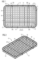
- FIG 1 illustrates a tray 10 for cooking food in an oven or a microwave oven in a schematic top view
- Fig.2 illustrates the tray 10 in a schematic perspective view.
- the tray 10 comprises a flat, non-flexible base plate 12 and at least one side wall 14 surrounding the base plate 12.
- the base plate 12 and the at least one side wall 14 are integrally formed.
- a plate is deformed to form the tray 10 with its base plate 12 and at least one side wall 14.
- the tray 10 comprises a rectangular base plate 12 with four side walls 14 adjoining the base plate 12 on its four sides.
- the base plate 12 and the side wall 14 have a lattice structure comprising a plurality of webs 16 and a plurality of openings 18 that were introduced in the plate by means of a laser (not shown). Alternatively the openings could have been introduced by punching out. At least 45% of the surface 20 formed by the base plate 12 and the four side walls 14, thus at least 45% of the surface of the entire plate, is formed or rather covered by the openings 18.
- the openings 18 are placed in regular intervals I and two webs 16 cross each other at a right angle, thus two webs overlapping crosswise.
- guiding means 22 are attached to the base plate 12 and the at least one side wall 14. More specifically, in this embodiment the guiding means 22 include a peripheral frame 24 that surrounds side walls 14 completely. Further the guiding means 22 include two support members 26 that is attached with its both ends 28a, 28b to the frame 24 and at its middle piece 30 (shown in dashed lines) is located at a bottom side 32 of the base plate 12.
- the tray 10 respectively the base plate 12 and the side walls 14 are for example made of aluminium or stainless steel with or without a coating.
- the base plate 12 and the at least one side wall 14 is made of high temperature plastics showing at least partially a self-heating behaviour.
- the base plate 12 and the four side walls 14 are provided with a coating that encloses the tray 10 completely.
- the coating which is an PTFE-based coating that is allowed for food contact and easy to clean, is applied to the tray in a subsequent manufacturing step.
- Fig. 3 shows a process for manufacturing the tray 10 illustrated in Fig. 1 and 2 .
- a plate 34 is provided and several openings 18 are introduced into the plate 34 using a laser 36.
- the corners 40 of the plate 34 may be not provided with openings 18 as subsequently the corners 40 of the plate 34 may be cutted diagonally a bit far along the cutting lines L that are illustrated in dashed lines. This simplifies deforming the four lateral edges 38 of the plate 34 in a subsequent step along the deforming respectively bending axes D, again illustrated by dashed lines and in direction of the illustrated arrows.
- guiding means 22 are attached to the base plate 12 and the at least one side wall 14 and a coating may be applied to the base plate 12 and the four side walls 14 in a further manufacturing step for obtaining a tray 10 as it is shown in Fig. 1 and 2 .
Landscapes
- Engineering & Computer Science (AREA)
- Food Science & Technology (AREA)
- Physics & Mathematics (AREA)
- Electromagnetism (AREA)
- Life Sciences & Earth Sciences (AREA)
- Chemical & Material Sciences (AREA)
- Combustion & Propulsion (AREA)
- Mechanical Engineering (AREA)
- General Engineering & Computer Science (AREA)
- Cookers (AREA)
- Package Specialized In Special Use (AREA)
Abstract
Description
- The present invention relates to a tray for cooking food in an oven or a microwave and a process for manufacturing such a tray.
- As consumers prepare food in their oven, for example different kinds of potato products or other vegetables, the results are not always convincing since conventional baking trays do not allow that all sides of the food are evenly baked. In order to achieve uniform cooking the food should be turned several times during the cooking process.
- For example, an insert in form of a closed basket is known, that is automatically rotated during the cooking process. For this purpose, however, a motor is required, which in turn increases the energy consumption.
-
DE 20 2009 003 589 U1 discloses a backing tray, preferably for backing frozen potato foodstuff, made out of expanded metall. Expandable metal can be very sharp-edged so that the surface of the food, which is prepared with such a tray, may be damaged. Therefore, food leftovers can easily set in the tray, whereby a cleaning of the tray is more difficult. - It is an object of the present invention to provide a tray for cooking food in an oven or a microwave that allows preparing food with a good quality and low energy consumption and a process for manufacturing such a tray.
- The first object is achieved by a tray for cooking food in an oven or in a microwave according to claim 1.
- According to claim 1 the present invention provides a tray for cooking food in an oven or in a microwave comprising
- a flat, non-flexible base plate,
- at least one side wall surrounding the base plate, whereby the base plate and the at least one side wall are integrally formed,
- the base plate and the at least one side wall having a lattice structure comprising a plurality of webs and a plurality of openings introduced by means of a laser and/or by punching out,
- guiding means attached to the base plate and/or the at least one side wall,
- a surface formed by the base plate and the at least one side wall, whereby at least 45% of the surface is formed by the plurality of openings.
- The core of the present invention is that the ratio of the webs to the openings is as minimal as possible, this means the tray is prepared by as little as possible of material and the thermal mass is significantly reduced. With other words: The tray shows a lattice structure whereby the openings define an open space and this open space is larger than 45%, preferably 50% and more preferably 60% of the space of the whole tray. That means an areal proportion of the plurality of openings is at least 45% of the total area of the tray, thus the area formed by the base plate and the side walls. This reduces the thermal mass being present in the oven and therefore results in lower energy consumption and a faster heat up of the tray. Thereby pre-heating the oven is not necessary what in turn saves time, energy and costs.
- Furthermore the openings are dimensioned such that a fall through of the food is prevented, so that there is no need to use a pan liner. Possibly running down oil gathers at the webs. As the hot air can flow around the food from all sides, no turning of the food during the baking process is required.
- The base plate and the at least one side wall are integrally formed. The plurality of openings were introduced by means of a laser or punched out, so that no expensive connection techniques are necessary. A flat base plate further simplifies applying a coating if desired.
- The tray comprises guiding means attached to the base plate and/or the at least one side wall for guiding and holding the tray in an oven or a microwave. The guiding means are for example configured such that they can engage with a recess that is provided in an inner wall of an oven for guiding the tray during inserting it into the oven or removing it therefrom and for supporting it during the cooking process. This has the advantage that the tray can be putted directly into the oven, no grid is required on which the tray can be placed so that the thermal mass inside the oven is further reduced.
- For use in a microwave the guiding means might be designed as a support to hold the tray at a distance from the bottom of the microwave, so that the food can be heated evenly from all sides. To avoid hot spots, the tray with the guiding means may additionally be placed on a turntable or a microwave stirrer may be used.
- Preferably, the plurality of openings are placed in regular intervals and two webs cross each other at a right angle. The openings thus have a rectangular or even square shape.
- In particular, the guiding means include a peripheral frame surrounding the at least one side wall. Such a frame might be formed as a wire frame or in the form of a bent rod that surrounds the tray respectively the at least one side wall completely and might be attached to the at least one side wall by known joining techniques such as welding.
- In a preferred embodiment, however, the guiding means include at least one support member that is attached at both ends to the frame and at its middle piece is located at a bottom side of the base plate. The middle piece of the support member may be also attached to the bottom of the base plate. For example, when the guiding means comprise at least two spaced apart support members, it is not necessary to fix the tray to the support member, as the tray is holded sufficiently horizontal by the support members. Therefore guiding means can be used with different types of tray, for example with trays made of different materials. The support member is particularly in form of a rod and attached parallel and congruently to one of the webs of the base plate in order not to cover the openings, what would lead to an impairment of the flow of hot air during the cooking process.
- For use of the tray in an oven, the tray respectively the base plate and the at least one side wall are preferably made of aluminium that has a good thermal conductivity.
- Alternatively the base plate and the at least one side wall is made of stainless steel.
- Another preferred embodiment provides that the base plate and the at least one side wall is made of high temperature plastics showing at least partially a self-heating behaviour. Thus the entire tray can consist of high temperature plastics with self-heating behaviour. Such a material is preferably used when the tray should be applied in a microwave. However it may also be sufficient that the tray is made of high temperature plastics comprising only an inner layer or an inner core that shows self-heating behaviour and a good heat distribution.
- For example microwave-heatable thermoplastic compositions may be used, which are formed by mixing a microwave receptive additive with a thermoplastic polymer. Polymers which may be used here are for example selected from polyolefins, polyamides, polycarbonates, polyesters, polylactic acid and polylactide polymers, polysulfones, polylactones, polyacetals, acrylonitrile-butadiene-styrene resins (ABS), polyphenyleneoxide (PPO), polyphenylene sulfide (PPS), styreneacrylonitrile resins (SAN), polyimides, styrene maleic anhydride (SMA), aromatic polyketones (PEEK, PEK, and PEKK), ethylene vinyl alcohol copolymer, and copolymers or mixtures thereof. The microwave receptive additives used are for example selected from elements, heavy metal salts, salt hydrates, complex hydrates, other simple hydrates, metal oxides complex oxides, metal sulfides/carbides/nitrides, semiconductors, ion and organic conductors.
- The degree to which any material will heat in the presence of a microwave field is defined by its dielectric loss factor. Also polar polymers without microwave receptive additives having a dielectric loss factor between 5·10-4 and 5·10-3 may be used for the tray that is intended for use in a microwave oven, for example PVC (polyvinylchloride) or PU (polyurethane).
- Preferably, the base plate and the at least one side wall are additionally provided with a coating that is allowed for food contact. The coating may enclose the tray respectively the base plate and the at least one side wall completely.
- In particular the coating is an enamel based coating and/or a PTFE (Polytetrafluoroethylene)-based coating and/or Sol-gel based coating and/or ceramic based coating. Firstly such a coating has the advantage that the food can be easily removed from the tray after cooking as it does not stick to the tray. Secondly, the tray is more easy to clean after the food preparation.
- The second object of the invention is achieved by a process for manufacturing an above-described tray according to claim 11.
- According to claim 11 the present invention provides a process for manufacturing a tray, comprising the following steps:
- providing a plate,
- introducing the plurality of openings into the plate by means of a laser and/or by punching out,
- deforming an edge of the plate to form the at least one side wall and the base plate,
- attaching the guiding means to the base plate and/or the at least one side wall.
- The plate, thus the lateral edges of the plate will be deformed respectively bent along at least one deformation respectively bending axis to form the base plate and the at least one side wall after having introduced the openings. The deforming step is carried out at elevated temperature. The edges of the plate is the maximum so far deformed until it forms an angle of 90° with the base plate. Before the deforming step, the plate might be cut at the corners for making it easier to bent the edges of the plate upwardly. The guiding means are attached to the base plate and /or the at least one side wall for example by using welding techniques.
- According to a preferred embodiment a coating is applied to the base plate and/or the at least one side wall in a subsequent step. As the base plate is flat, the coating can be applied in a simple manner. Materials used as a coating have been mentioned above.
- Novel and inventive features of the present invention are set forth in the appended claims.
- The present invention will be described in further detail with reference to the drawing, in which
- FIG 1
- illustrates a schematic top view of a tray according to the present invention,
- FIG 2
- illustrates a schematic perspective view of a tray according to the present invention,
- FIG 3
- illustrates a schematic view of a process for manufacturing a tray according to the present invention.
-
FIG 1 illustrates atray 10 for cooking food in an oven or a microwave oven in a schematic top view,Fig.2 illustrates thetray 10 in a schematic perspective view. - The
tray 10 comprises a flat,non-flexible base plate 12 and at least oneside wall 14 surrounding thebase plate 12. Thebase plate 12 and the at least oneside wall 14 are integrally formed. During the manufacturing process a plate is deformed to form thetray 10 with itsbase plate 12 and at least oneside wall 14. According toFig. 1 thetray 10 comprises arectangular base plate 12 with fourside walls 14 adjoining thebase plate 12 on its four sides. - The
base plate 12 and theside wall 14 have a lattice structure comprising a plurality ofwebs 16 and a plurality ofopenings 18 that were introduced in the plate by means of a laser (not shown). Alternatively the openings could have been introduced by punching out. At least 45% of thesurface 20 formed by thebase plate 12 and the fourside walls 14, thus at least 45% of the surface of the entire plate, is formed or rather covered by theopenings 18. Theopenings 18 are placed in regular intervals I and twowebs 16 cross each other at a right angle, thus two webs overlapping crosswise. - Furthermore, guiding means 22 are attached to the
base plate 12 and the at least oneside wall 14. More specifically, in this embodiment the guiding means 22 include aperipheral frame 24 that surroundsside walls 14 completely. Further the guiding means 22 include twosupport members 26 that is attached with its bothends frame 24 and at its middle piece 30 (shown in dashed lines) is located at abottom side 32 of thebase plate 12. - In principle the
tray 10 respectively thebase plate 12 and theside walls 14 are for example made of aluminium or stainless steel with or without a coating. In this case, thebase plate 12 and the at least oneside wall 14 is made of high temperature plastics showing at least partially a self-heating behaviour. Additionally thebase plate 12 and the fourside walls 14 are provided with a coating that encloses thetray 10 completely. The coating, which is an PTFE-based coating that is allowed for food contact and easy to clean, is applied to the tray in a subsequent manufacturing step. -
Fig. 3 shows a process for manufacturing thetray 10 illustrated inFig. 1 and 2 . Aplate 34 is provided andseveral openings 18 are introduced into theplate 34 using alaser 36. Thecorners 40 of theplate 34 may be not provided withopenings 18 as subsequently thecorners 40 of theplate 34 may be cutted diagonally a bit far along the cutting lines L that are illustrated in dashed lines. This simplifies deforming the fourlateral edges 38 of theplate 34 in a subsequent step along the deforming respectively bending axes D, again illustrated by dashed lines and in direction of the illustrated arrows. Afterwards, guiding means 22 are attached to thebase plate 12 and the at least oneside wall 14 and a coating may be applied to thebase plate 12 and the fourside walls 14 in a further manufacturing step for obtaining atray 10 as it is shown inFig. 1 and 2 . - Although an illustrative embodiment of the present invention has been described herein with reference to the accompanying drawing, it is to be understood that the present invention is not limited to that precise embodiment, and that various other changes and modifications may be affected therein by one skilled in the art without departing from the scope or spirit of the invention. All such changes and modifications are intended to be included within the scope of the invention as defined by the appended claims.
-
- 10
- tray
- 12
- base plate
- 14
- side wall
- 16
- web
- 18
- opening
- 20
- surface
- 22
- guiding means
- 24
- frame
- 26
- support member
- 28a, 28b
- end of support member
- 30
- middle piece of support member
- 32
- bottom side of the base plate
- 34
- plate
- 36
- laser
- 38
- edges of the
plate 34 - 40
- corners of the
plate 34 - I
- interval
- L
- cutting lines
- D
- deforming/bending axis
Claims (11)
characterized in that the guiding means (22) include a peripheral frame (24) surrounding the at least one side wall (14).
characterized in that the guiding means (22) include at least one support member (26) that is attached at both ends (28a, 28b) to the frame (24) and at its middle piece (30) is located to a bottom side (32) of the base plate (12).
characterized in that
the base plate (12) and the at least one side wall (14) are made of aluminium.
characterized in that
the base plate (12) and the at least one side wall (14) is made of stainless steel.
characterized in that
the base plate (12) and the at least one side wall (14) is made of high temperature plastics showing at least partially a self-heating behaviour.
characterized in that
the base plate (12) and the at least one side wall (14) are provided with a coating.
characterized in that
the coating is an enamel based coating and/or a PTFE-based coating and/or Sol-gel based coating and/or ceramic based coating.
Priority Applications (6)
| Application Number | Priority Date | Filing Date | Title |
|---|---|---|---|
| EP15174966.0A EP3113576B1 (en) | 2015-07-02 | 2015-07-02 | Tray for cooking food and process for manufacturing a tray |
| AU2016286937A AU2016286937A1 (en) | 2015-07-02 | 2016-01-27 | Tray for cooking food and process for manufacturing a tray |
| PCT/EP2016/051610 WO2017001061A1 (en) | 2015-07-02 | 2016-01-27 | Tray for cooking food and process for manufacturing a tray |
| CN201680037255.2A CN108141930B (en) | 2015-07-02 | 2016-01-27 | Tray for cooking food and method of manufacturing the same |
| BR112017028418-9A BR112017028418B1 (en) | 2015-07-02 | 2016-01-27 | TRAY FOR COOKING FOOD IN AN OVEN AND PROCESS FOR MANUFACTURING A TRAY |
| US15/578,728 US20180213802A1 (en) | 2015-07-02 | 2016-01-27 | Tray for cooking food and process for manufacturing a tray |
Applications Claiming Priority (1)
| Application Number | Priority Date | Filing Date | Title |
|---|---|---|---|
| EP15174966.0A EP3113576B1 (en) | 2015-07-02 | 2015-07-02 | Tray for cooking food and process for manufacturing a tray |
Publications (2)
| Publication Number | Publication Date |
|---|---|
| EP3113576A1 true EP3113576A1 (en) | 2017-01-04 |
| EP3113576B1 EP3113576B1 (en) | 2017-09-13 |
Family
ID=53502557
Family Applications (1)
| Application Number | Title | Priority Date | Filing Date |
|---|---|---|---|
| EP15174966.0A Active EP3113576B1 (en) | 2015-07-02 | 2015-07-02 | Tray for cooking food and process for manufacturing a tray |
Country Status (6)
| Country | Link |
|---|---|
| US (1) | US20180213802A1 (en) |
| EP (1) | EP3113576B1 (en) |
| CN (1) | CN108141930B (en) |
| AU (1) | AU2016286937A1 (en) |
| BR (1) | BR112017028418B1 (en) |
| WO (1) | WO2017001061A1 (en) |
Cited By (1)
| Publication number | Priority date | Publication date | Assignee | Title |
|---|---|---|---|---|
| EP3804585A1 (en) | 2019-10-10 | 2021-04-14 | Electrolux Appliances Aktiebolag | Method for operating a cooking oven |
Families Citing this family (3)
| Publication number | Priority date | Publication date | Assignee | Title |
|---|---|---|---|---|
| US11272828B2 (en) | 2020-07-14 | 2022-03-15 | Haier Us Appliance Solutions, Inc. | Wash rack for a dishwasher and method of making a wash rack |
| US12207758B2 (en) * | 2021-06-17 | 2025-01-28 | Conair Llc | Multifunction toaster oven |
| CN115804522A (en) * | 2021-09-13 | 2023-03-17 | 广东美的厨房电器制造有限公司 | cooking utensils |
Citations (4)
| Publication number | Priority date | Publication date | Assignee | Title |
|---|---|---|---|---|
| WO1995033360A1 (en) * | 1993-02-12 | 1995-12-07 | Kansas State University Research Foundation | Microwave baking pan |
| US6213005B1 (en) * | 1999-12-06 | 2001-04-10 | Aleksandr Sherman | Reinforced cooking pan |
| GB2432509A (en) * | 2005-10-07 | 2007-05-30 | Guy Darell Unwin | A meshed baking tray |
| DE202009003589U1 (en) | 2009-03-13 | 2009-05-28 | Moos, Björn | Oven grate |
Family Cites Families (5)
| Publication number | Priority date | Publication date | Assignee | Title |
|---|---|---|---|---|
| US7850035B2 (en) * | 2004-07-01 | 2010-12-14 | Mastrad Sa | Baking sheet |
| KR100677273B1 (en) * | 2005-04-20 | 2007-02-02 | 엘지전자 주식회사 | Defrosting container for microwave oven |
| US7938285B2 (en) * | 2006-11-22 | 2011-05-10 | Charcoal Companion Incorporated | Wood chip soaker |
| CN103225830B (en) * | 2007-01-22 | 2016-01-20 | 印刷包装国际公司 | Heating using microwave component and the blank for the formation of this component |
| DE202010010304U1 (en) * | 2010-07-16 | 2010-09-30 | Silit-Werke Gmbh & Co. Kg | Steamers |
-
2015
- 2015-07-02 EP EP15174966.0A patent/EP3113576B1/en active Active
-
2016
- 2016-01-27 US US15/578,728 patent/US20180213802A1/en not_active Abandoned
- 2016-01-27 WO PCT/EP2016/051610 patent/WO2017001061A1/en not_active Ceased
- 2016-01-27 AU AU2016286937A patent/AU2016286937A1/en not_active Abandoned
- 2016-01-27 BR BR112017028418-9A patent/BR112017028418B1/en active IP Right Grant
- 2016-01-27 CN CN201680037255.2A patent/CN108141930B/en active Active
Patent Citations (4)
| Publication number | Priority date | Publication date | Assignee | Title |
|---|---|---|---|---|
| WO1995033360A1 (en) * | 1993-02-12 | 1995-12-07 | Kansas State University Research Foundation | Microwave baking pan |
| US6213005B1 (en) * | 1999-12-06 | 2001-04-10 | Aleksandr Sherman | Reinforced cooking pan |
| GB2432509A (en) * | 2005-10-07 | 2007-05-30 | Guy Darell Unwin | A meshed baking tray |
| DE202009003589U1 (en) | 2009-03-13 | 2009-05-28 | Moos, Björn | Oven grate |
Cited By (1)
| Publication number | Priority date | Publication date | Assignee | Title |
|---|---|---|---|---|
| EP3804585A1 (en) | 2019-10-10 | 2021-04-14 | Electrolux Appliances Aktiebolag | Method for operating a cooking oven |
Also Published As
| Publication number | Publication date |
|---|---|
| CN108141930A (en) | 2018-06-08 |
| BR112017028418B1 (en) | 2022-11-16 |
| WO2017001061A1 (en) | 2017-01-05 |
| AU2016286937A1 (en) | 2017-11-30 |
| BR112017028418A2 (en) | 2018-08-28 |
| US20180213802A1 (en) | 2018-08-02 |
| CN108141930B (en) | 2021-01-15 |
| EP3113576B1 (en) | 2017-09-13 |
Similar Documents
| Publication | Publication Date | Title |
|---|---|---|
| EP3113576B1 (en) | Tray for cooking food and process for manufacturing a tray | |
| DE60216053T2 (en) | APPARATUS AND METHOD FOR FAST HEATING OF PACKED MEALS | |
| US6229131B1 (en) | Microwave cooking grill and steamer | |
| US3716687A (en) | Method and apparatus for cooking | |
| US20150305093A1 (en) | Countertop oven with thin-film heating element | |
| US9942951B2 (en) | Microwave heating element | |
| AU2007232327B2 (en) | Microwavable packaging for food products | |
| EP3014951A1 (en) | Method and device for processing frozen food | |
| US4603052A (en) | Method for oven-heating frozen fried foods | |
| US7973264B2 (en) | Toaster oven with low-profile heating elements | |
| KR100478455B1 (en) | Microwave Oven | |
| EP1935300A1 (en) | Food support for use in a microwave oven | |
| US20190364909A1 (en) | Formed Cooked Batter Food Containment System | |
| US4771155A (en) | Apparatus for promoting the uniform heating of a food product in a radiant energy field | |
| US4996404A (en) | Cooking apparatus for roasting food | |
| KR100585702B1 (en) | Microwave thawing plate | |
| WO2017021260A1 (en) | Apparatus for cooking oven-baked products and the like | |
| JP3254200U (en) | food supports | |
| US20070110866A1 (en) | Apparatus and method for holding tortilla during cooking | |
| US20230240474A1 (en) | Toasting tray for buns | |
| DE102013108688B4 (en) | Twin-wall insulated tray | |
| US10016091B1 (en) | Toaster grill | |
| JP4183662B2 (en) | Food heating method using microwave oven and food heating set for microwave oven | |
| US20260013667A1 (en) | Toaster-Engageable Toasting Basket | |
| DE102019119410A1 (en) | MODULAR MICROWAVE OVEN SYSTEM |
Legal Events
| Date | Code | Title | Description |
|---|---|---|---|
| PUAI | Public reference made under article 153(3) epc to a published international application that has entered the european phase |
Free format text: ORIGINAL CODE: 0009012 |
|
| AK | Designated contracting states |
Kind code of ref document: A1 Designated state(s): AL AT BE BG CH CY CZ DE DK EE ES FI FR GB GR HR HU IE IS IT LI LT LU LV MC MK MT NL NO PL PT RO RS SE SI SK SM TR |
|
| AX | Request for extension of the european patent |
Extension state: BA ME |
|
| GRAP | Despatch of communication of intention to grant a patent |
Free format text: ORIGINAL CODE: EPIDOSNIGR1 |
|
| 17P | Request for examination filed |
Effective date: 20170320 |
|
| RBV | Designated contracting states (corrected) |
Designated state(s): AL AT BE BG CH CY CZ DE DK EE ES FI FR GB GR HR HU IE IS IT LI LT LU LV MC MK MT NL NO PL PT RO RS SE SI SK SM TR |
|
| INTG | Intention to grant announced |
Effective date: 20170424 |
|
| GRAS | Grant fee paid |
Free format text: ORIGINAL CODE: EPIDOSNIGR3 |
|
| GRAA | (expected) grant |
Free format text: ORIGINAL CODE: 0009210 |
|
| AK | Designated contracting states |
Kind code of ref document: B1 Designated state(s): AL AT BE BG CH CY CZ DE DK EE ES FI FR GB GR HR HU IE IS IT LI LT LU LV MC MK MT NL NO PL PT RO RS SE SI SK SM TR |
|
| REG | Reference to a national code |
Ref country code: GB Ref legal event code: FG4D |
|
| REG | Reference to a national code |
Ref country code: CH Ref legal event code: EP |
|
| REG | Reference to a national code |
Ref country code: IE Ref legal event code: FG4D |
|
| REG | Reference to a national code |
Ref country code: AT Ref legal event code: REF Ref document number: 929386 Country of ref document: AT Kind code of ref document: T Effective date: 20171015 |
|
| REG | Reference to a national code |
Ref country code: DE Ref legal event code: R096 Ref document number: 602015004625 Country of ref document: DE |
|
| REG | Reference to a national code |
Ref country code: NL Ref legal event code: MP Effective date: 20170913 |
|
| REG | Reference to a national code |
Ref country code: LT Ref legal event code: MG4D |
|
| PG25 | Lapsed in a contracting state [announced via postgrant information from national office to epo] |
Ref country code: FI Free format text: LAPSE BECAUSE OF FAILURE TO SUBMIT A TRANSLATION OF THE DESCRIPTION OR TO PAY THE FEE WITHIN THE PRESCRIBED TIME-LIMIT Effective date: 20170913 Ref country code: NO Free format text: LAPSE BECAUSE OF FAILURE TO SUBMIT A TRANSLATION OF THE DESCRIPTION OR TO PAY THE FEE WITHIN THE PRESCRIBED TIME-LIMIT Effective date: 20171213 Ref country code: SE Free format text: LAPSE BECAUSE OF FAILURE TO SUBMIT A TRANSLATION OF THE DESCRIPTION OR TO PAY THE FEE WITHIN THE PRESCRIBED TIME-LIMIT Effective date: 20170913 Ref country code: LT Free format text: LAPSE BECAUSE OF FAILURE TO SUBMIT A TRANSLATION OF THE DESCRIPTION OR TO PAY THE FEE WITHIN THE PRESCRIBED TIME-LIMIT Effective date: 20170913 Ref country code: HR Free format text: LAPSE BECAUSE OF FAILURE TO SUBMIT A TRANSLATION OF THE DESCRIPTION OR TO PAY THE FEE WITHIN THE PRESCRIBED TIME-LIMIT Effective date: 20170913 |
|
| REG | Reference to a national code |
Ref country code: AT Ref legal event code: MK05 Ref document number: 929386 Country of ref document: AT Kind code of ref document: T Effective date: 20170913 |
|
| PG25 | Lapsed in a contracting state [announced via postgrant information from national office to epo] |
Ref country code: GR Free format text: LAPSE BECAUSE OF FAILURE TO SUBMIT A TRANSLATION OF THE DESCRIPTION OR TO PAY THE FEE WITHIN THE PRESCRIBED TIME-LIMIT Effective date: 20171214 Ref country code: RS Free format text: LAPSE BECAUSE OF FAILURE TO SUBMIT A TRANSLATION OF THE DESCRIPTION OR TO PAY THE FEE WITHIN THE PRESCRIBED TIME-LIMIT Effective date: 20170913 Ref country code: ES Free format text: LAPSE BECAUSE OF FAILURE TO SUBMIT A TRANSLATION OF THE DESCRIPTION OR TO PAY THE FEE WITHIN THE PRESCRIBED TIME-LIMIT Effective date: 20170913 Ref country code: BG Free format text: LAPSE BECAUSE OF FAILURE TO SUBMIT A TRANSLATION OF THE DESCRIPTION OR TO PAY THE FEE WITHIN THE PRESCRIBED TIME-LIMIT Effective date: 20171213 Ref country code: LV Free format text: LAPSE BECAUSE OF FAILURE TO SUBMIT A TRANSLATION OF THE DESCRIPTION OR TO PAY THE FEE WITHIN THE PRESCRIBED TIME-LIMIT Effective date: 20170913 |
|
| PG25 | Lapsed in a contracting state [announced via postgrant information from national office to epo] |
Ref country code: NL Free format text: LAPSE BECAUSE OF FAILURE TO SUBMIT A TRANSLATION OF THE DESCRIPTION OR TO PAY THE FEE WITHIN THE PRESCRIBED TIME-LIMIT Effective date: 20170913 |
|
| PG25 | Lapsed in a contracting state [announced via postgrant information from national office to epo] |
Ref country code: CZ Free format text: LAPSE BECAUSE OF FAILURE TO SUBMIT A TRANSLATION OF THE DESCRIPTION OR TO PAY THE FEE WITHIN THE PRESCRIBED TIME-LIMIT Effective date: 20170913 Ref country code: PL Free format text: LAPSE BECAUSE OF FAILURE TO SUBMIT A TRANSLATION OF THE DESCRIPTION OR TO PAY THE FEE WITHIN THE PRESCRIBED TIME-LIMIT Effective date: 20170913 |
|
| PG25 | Lapsed in a contracting state [announced via postgrant information from national office to epo] |
Ref country code: SK Free format text: LAPSE BECAUSE OF FAILURE TO SUBMIT A TRANSLATION OF THE DESCRIPTION OR TO PAY THE FEE WITHIN THE PRESCRIBED TIME-LIMIT Effective date: 20170913 Ref country code: EE Free format text: LAPSE BECAUSE OF FAILURE TO SUBMIT A TRANSLATION OF THE DESCRIPTION OR TO PAY THE FEE WITHIN THE PRESCRIBED TIME-LIMIT Effective date: 20170913 Ref country code: SM Free format text: LAPSE BECAUSE OF FAILURE TO SUBMIT A TRANSLATION OF THE DESCRIPTION OR TO PAY THE FEE WITHIN THE PRESCRIBED TIME-LIMIT Effective date: 20170913 Ref country code: IS Free format text: LAPSE BECAUSE OF FAILURE TO SUBMIT A TRANSLATION OF THE DESCRIPTION OR TO PAY THE FEE WITHIN THE PRESCRIBED TIME-LIMIT Effective date: 20180113 Ref country code: AT Free format text: LAPSE BECAUSE OF FAILURE TO SUBMIT A TRANSLATION OF THE DESCRIPTION OR TO PAY THE FEE WITHIN THE PRESCRIBED TIME-LIMIT Effective date: 20170913 |
|
| REG | Reference to a national code |
Ref country code: DE Ref legal event code: R097 Ref document number: 602015004625 Country of ref document: DE |
|
| PLBE | No opposition filed within time limit |
Free format text: ORIGINAL CODE: 0009261 |
|
| STAA | Information on the status of an ep patent application or granted ep patent |
Free format text: STATUS: NO OPPOSITION FILED WITHIN TIME LIMIT |
|
| REG | Reference to a national code |
Ref country code: FR Ref legal event code: PLFP Year of fee payment: 4 |
|
| PG25 | Lapsed in a contracting state [announced via postgrant information from national office to epo] |
Ref country code: DK Free format text: LAPSE BECAUSE OF FAILURE TO SUBMIT A TRANSLATION OF THE DESCRIPTION OR TO PAY THE FEE WITHIN THE PRESCRIBED TIME-LIMIT Effective date: 20170913 |
|
| 26N | No opposition filed |
Effective date: 20180614 |
|
| REG | Reference to a national code |
Ref country code: CH Ref legal event code: PL |
|
| PG25 | Lapsed in a contracting state [announced via postgrant information from national office to epo] |
Ref country code: LU Free format text: LAPSE BECAUSE OF NON-PAYMENT OF DUE FEES Effective date: 20180702 Ref country code: MC Free format text: LAPSE BECAUSE OF FAILURE TO SUBMIT A TRANSLATION OF THE DESCRIPTION OR TO PAY THE FEE WITHIN THE PRESCRIBED TIME-LIMIT Effective date: 20170913 |
|
| REG | Reference to a national code |
Ref country code: BE Ref legal event code: MM Effective date: 20180731 |
|
| REG | Reference to a national code |
Ref country code: IE Ref legal event code: MM4A |
|
| PG25 | Lapsed in a contracting state [announced via postgrant information from national office to epo] |
Ref country code: CH Free format text: LAPSE BECAUSE OF NON-PAYMENT OF DUE FEES Effective date: 20180731 Ref country code: LI Free format text: LAPSE BECAUSE OF NON-PAYMENT OF DUE FEES Effective date: 20180731 Ref country code: IE Free format text: LAPSE BECAUSE OF NON-PAYMENT OF DUE FEES Effective date: 20180702 |
|
| PG25 | Lapsed in a contracting state [announced via postgrant information from national office to epo] |
Ref country code: BE Free format text: LAPSE BECAUSE OF NON-PAYMENT OF DUE FEES Effective date: 20180731 |
|
| PG25 | Lapsed in a contracting state [announced via postgrant information from national office to epo] |
Ref country code: MT Free format text: LAPSE BECAUSE OF NON-PAYMENT OF DUE FEES Effective date: 20180702 |
|
| PG25 | Lapsed in a contracting state [announced via postgrant information from national office to epo] |
Ref country code: TR Free format text: LAPSE BECAUSE OF FAILURE TO SUBMIT A TRANSLATION OF THE DESCRIPTION OR TO PAY THE FEE WITHIN THE PRESCRIBED TIME-LIMIT Effective date: 20170913 |
|
| PG25 | Lapsed in a contracting state [announced via postgrant information from national office to epo] |
Ref country code: PT Free format text: LAPSE BECAUSE OF FAILURE TO SUBMIT A TRANSLATION OF THE DESCRIPTION OR TO PAY THE FEE WITHIN THE PRESCRIBED TIME-LIMIT Effective date: 20170913 |
|
| PG25 | Lapsed in a contracting state [announced via postgrant information from national office to epo] |
Ref country code: RO Free format text: LAPSE BECAUSE OF FAILURE TO SUBMIT A TRANSLATION OF THE DESCRIPTION OR TO PAY THE FEE WITHIN THE PRESCRIBED TIME-LIMIT Effective date: 20170913 Ref country code: MK Free format text: LAPSE BECAUSE OF NON-PAYMENT OF DUE FEES Effective date: 20170913 Ref country code: HU Free format text: LAPSE BECAUSE OF FAILURE TO SUBMIT A TRANSLATION OF THE DESCRIPTION OR TO PAY THE FEE WITHIN THE PRESCRIBED TIME-LIMIT; INVALID AB INITIO Effective date: 20150702 Ref country code: CY Free format text: LAPSE BECAUSE OF FAILURE TO SUBMIT A TRANSLATION OF THE DESCRIPTION OR TO PAY THE FEE WITHIN THE PRESCRIBED TIME-LIMIT Effective date: 20170913 |
|
| PG25 | Lapsed in a contracting state [announced via postgrant information from national office to epo] |
Ref country code: AL Free format text: LAPSE BECAUSE OF FAILURE TO SUBMIT A TRANSLATION OF THE DESCRIPTION OR TO PAY THE FEE WITHIN THE PRESCRIBED TIME-LIMIT Effective date: 20170913 |
|
| PG25 | Lapsed in a contracting state [announced via postgrant information from national office to epo] |
Ref country code: SI Free format text: LAPSE BECAUSE OF NON-PAYMENT OF DUE FEES Effective date: 20180702 |
|
| P01 | Opt-out of the competence of the unified patent court (upc) registered |
Effective date: 20230625 |
|
| PGFP | Annual fee paid to national office [announced via postgrant information from national office to epo] |
Ref country code: DE Payment date: 20250728 Year of fee payment: 11 |
|
| PGFP | Annual fee paid to national office [announced via postgrant information from national office to epo] |
Ref country code: IT Payment date: 20250721 Year of fee payment: 11 |
|
| PGFP | Annual fee paid to national office [announced via postgrant information from national office to epo] |
Ref country code: GB Payment date: 20250722 Year of fee payment: 11 |
|
| PGFP | Annual fee paid to national office [announced via postgrant information from national office to epo] |
Ref country code: FR Payment date: 20250725 Year of fee payment: 11 |