EP3113562A1 - Method for detecting data transmission and data reception, and base station and user device - Google Patents
Method for detecting data transmission and data reception, and base station and user device Download PDFInfo
- Publication number
- EP3113562A1 EP3113562A1 EP15755110.2A EP15755110A EP3113562A1 EP 3113562 A1 EP3113562 A1 EP 3113562A1 EP 15755110 A EP15755110 A EP 15755110A EP 3113562 A1 EP3113562 A1 EP 3113562A1
- Authority
- EP
- European Patent Office
- Prior art keywords
- data
- physical resources
- onto
- pieces
- mapped
- Prior art date
- Legal status (The legal status is an assumption and is not a legal conclusion. Google has not performed a legal analysis and makes no representation as to the accuracy of the status listed.)
- Granted
Links
Images



Classifications
-
- H—ELECTRICITY
- H04—ELECTRIC COMMUNICATION TECHNIQUE
- H04L—TRANSMISSION OF DIGITAL INFORMATION, e.g. TELEGRAPHIC COMMUNICATION
- H04L5/00—Arrangements affording multiple use of the transmission path
- H04L5/003—Arrangements for allocating sub-channels of the transmission path
- H04L5/0044—Allocation of payload; Allocation of data channels, e.g. PDSCH or PUSCH
-
- H—ELECTRICITY
- H04—ELECTRIC COMMUNICATION TECHNIQUE
- H04W—WIRELESS COMMUNICATION NETWORKS
- H04W72/00—Local resource management
- H04W72/50—Allocation or scheduling criteria for wireless resources
- H04W72/54—Allocation or scheduling criteria for wireless resources based on quality criteria
- H04W72/541—Allocation or scheduling criteria for wireless resources based on quality criteria using the level of interference
-
- H—ELECTRICITY
- H04—ELECTRIC COMMUNICATION TECHNIQUE
- H04B—TRANSMISSION
- H04B7/00—Radio transmission systems, i.e. using radiation field
- H04B7/02—Diversity systems; Multi-antenna system, i.e. transmission or reception using multiple antennas
- H04B7/04—Diversity systems; Multi-antenna system, i.e. transmission or reception using multiple antennas using two or more spaced independent antennas
- H04B7/06—Diversity systems; Multi-antenna system, i.e. transmission or reception using multiple antennas using two or more spaced independent antennas at the transmitting station
- H04B7/0613—Diversity systems; Multi-antenna system, i.e. transmission or reception using multiple antennas using two or more spaced independent antennas at the transmitting station using simultaneous transmission
- H04B7/0615—Diversity systems; Multi-antenna system, i.e. transmission or reception using multiple antennas using two or more spaced independent antennas at the transmitting station using simultaneous transmission of weighted versions of same signal
-
- H—ELECTRICITY
- H04—ELECTRIC COMMUNICATION TECHNIQUE
- H04L—TRANSMISSION OF DIGITAL INFORMATION, e.g. TELEGRAPHIC COMMUNICATION
- H04L5/00—Arrangements affording multiple use of the transmission path
- H04L5/0001—Arrangements for dividing the transmission path
- H04L5/0014—Three-dimensional division
- H04L5/0023—Time-frequency-space
-
- H—ELECTRICITY
- H04—ELECTRIC COMMUNICATION TECHNIQUE
- H04L—TRANSMISSION OF DIGITAL INFORMATION, e.g. TELEGRAPHIC COMMUNICATION
- H04L5/00—Arrangements affording multiple use of the transmission path
- H04L5/003—Arrangements for allocating sub-channels of the transmission path
- H04L5/0037—Inter-user or inter-terminal allocation
-
- H—ELECTRICITY
- H04—ELECTRIC COMMUNICATION TECHNIQUE
- H04L—TRANSMISSION OF DIGITAL INFORMATION, e.g. TELEGRAPHIC COMMUNICATION
- H04L5/00—Arrangements affording multiple use of the transmission path
- H04L5/003—Arrangements for allocating sub-channels of the transmission path
- H04L5/0058—Allocation criteria
- H04L5/0071—Allocation based on fairness other than the proportional kind
-
- H—ELECTRICITY
- H04—ELECTRIC COMMUNICATION TECHNIQUE
- H04W—WIRELESS COMMUNICATION NETWORKS
- H04W72/00—Local resource management
- H04W72/50—Allocation or scheduling criteria for wireless resources
- H04W72/51—Allocation or scheduling criteria for wireless resources based on terminal or device properties
-
- H—ELECTRICITY
- H04—ELECTRIC COMMUNICATION TECHNIQUE
- H04W—WIRELESS COMMUNICATION NETWORKS
- H04W72/00—Local resource management
- H04W72/50—Allocation or scheduling criteria for wireless resources
- H04W72/53—Allocation or scheduling criteria for wireless resources based on regulatory allocation policies
-
- H—ELECTRICITY
- H04—ELECTRIC COMMUNICATION TECHNIQUE
- H04L—TRANSMISSION OF DIGITAL INFORMATION, e.g. TELEGRAPHIC COMMUNICATION
- H04L5/00—Arrangements affording multiple use of the transmission path
- H04L5/0001—Arrangements for dividing the transmission path
- H04L5/0014—Three-dimensional division
- H04L5/0016—Time-frequency-code
Definitions
- the present invention relates to the field of communications, and particularly to a method for transmitting data, a method for receiving and detecting data, a base station, and a user equipment.
- the 4 th Generation (4G) mobile communication system is deigned with the underlying ideas of a linear receiver and orthogonal transmission.
- the linear receiver is adopted because the linear receiver is easy to implement in engineering while guaranteeing the performance thereof; and orthogonal transmission is adopted so that a receiver can be easy to implement in engineering due to orthogonal transmission.
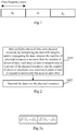
- Fig.1 is a schematic diagram of the orthogonal design where different data are transmitted respectively over orthogonal physical resources in such a way that each of the data is transmitted over corresponding each of the physical resources, and the respective data are orthogonal without any interference to each other.
- the capacity of a multi-user transmission system is out of reach by the orthogonal system due to a limited number of radio resources.
- a drawback in orthogonal transmission of data lies in a low capacity of the system, i.e., a low data transmission capacity of the system.
- Embodiments of the invention provide a method for transmitting data, a method for receiving and detecting data, a base station, and a user equipment, in a non-orthogonal mode so as to improve the data transmission capacity of a communication system.
- An embodiment of the invention provides a method for transmitting data, the method including:
- the data transmission capacity of a communication system can be improved.
- the number of pieces of data mapped onto each physical resource is no more than the number of physical resources.
- the data mapped onto the same physical resource are superimposed and then transmitted.
- the pieces of data are divided into multiple layers, wherein the number of physical resources onto which each piece of data in the preceding layer is mapped is larger than the number of physical resources onto which each piece of data in the succeeding layer is mapped.
- the data in different layers are multiplied with different weights, wherein the weight of the preceding layer is more than the weight of the succeeding layer, and the different data in the same layer are multiplied with the same weight.
- the pieces of data belong to at least two users.
- An embodiment of the invention further provides a method for receiving and detecting data, the method including:
- the data transmission capacity of a communication system can be improved.
- the data transmission capacity of a communication system can be improved.
- the number of pieces of data mapped onto each physical resource is no more than the number of physical resources.
- the data mapped onto the same physical resource are superimposed and then transmitted.
- the pieces of data are divided into multiple layers, wherein the number of physical resources onto which each piece of data in the preceding layer is mapped is larger than the number of physical resources onto which each piece of data in the succeeding layer is mapped.
- the pieces of data belong to at least two users.
- the data transmission capacity of a communication system can be improved.
- the bus architecture can include any number of interconnected buses and bridges to link together various circuits including one or more processors represented by the processor, and one or more memories represented by the memory.
- the bus architecture can further link together various other circuits, e.g., peripheral devices, a voltage stabilizer, a power management circuit, etc., and all of these circuits are well known in the art, so a further description thereof will be omitted in this context.
- an embodiment of the invention further provides a user equipment including:
- the bus architecture can include any number of interconnected buses and bridges to link together various circuits including one or more processors represented by the processor, and one or more memories represented by the memory.
- the bus architecture can further link together various other circuits, e.g., peripheral devices, a voltage stabilizer, a power management circuit, etc., and all of these circuits are well known in the art, so a further description thereof will be omitted in this context.
- the embodiments of the invention provide a method for transmitting data, a method for receiving and detecting data, a base station, and a user equipment, in a non-orthogonal mode.
- the base station When transmitting data, the base station firstly maps plurality pieces of data onto physical resources by multiplying the data with the weights, and/or conjugating the data, wherein the number of physical resources is no more than the number of pieces of data, each piece of data is mapped onto at least one of the physical resources, and the number of physical resources onto which each piece of data is mapped is not exactly the same as each other, and the base station then transmits the data over the physical resources, so that more data are transmitted over less physical resources to thereby improve the data transmission capacity of the communication system.
- Embodiments of the invention provide a method for transmitting data, a method for receiving and detecting data, a base station, and a user equipment, in a non-orthogonal mode.
- the base station When transmitting data, the base station firstly maps plurality pieces of data onto physical resources by multiplying the data with weights, and/or conjugating the data, wherein the number of physical resources is no more than the number of pieces of data, each piece of data is mapped onto at least one of the physical resources, and the number of physical resources onto which each piece of data is mapped is not exactly the same as each other, and the base station then transmits the data over the physical resources, so that more data are transmitted over less physical resources to thereby improve the data transmission capacity of the communication system.
- a method for transmitting data includes:
- the step S201 is to map multiples pieces of data onto physical resources by multiplying the data with weights, and/or conjugating the data, wherein the number of physical resources is no more than the number of pieces of data, each piece of data is mapped onto at least one of the physical resources, and the number of physical resources onto which each piece of data is mapped is not exactly the same as each other;
- the step S202 is to transmit the data over the physical resources.
- the data transmission capacity of the communication system can be improved.
- the number of pieces of data transmitted over each physical resource can be more than the number of physical resources, but in order to avoid the resources from being wasted, the number of pieces of data mapped onto each physical resource is no more than the number of physical resources.
- the data over the same physical resource can be transmitted by superimposition, that is, the data mapped onto the same physical resource are superimposed and then transmitted, where the data are superimposed linearly.
- pieces of data when pieces of data are mapped, they can be divided into multiple layers, and data in different layers are multiplied with different weights, where the weight of the preceding layer is more than the weight of the succeeding layer, and the different data in the same layer are multiplied with the same weight; and/or conjugating data in each layer, where the number of physical resources onto which each piece of data in the preceding layer is mapped is larger than the number of physical resources onto which each piece of data in the succeeding layer is mapped.
- the different data divided into the same layer may be mapped onto the same number of physical resources.
- pieces of data may belong to the same user, or may belong to at least two users.
- the base station will firstly divide N pieces of data of the at least two users into K layers; and then transmit the N pieces of data over a total number M of uncorrelated physical resources, where N>M; and each piece of data in the same layer is transmitted over the same number of uncorrelated physical resources, and the number of uncorrelated physical resources over which each piece of data in the layer is transmitted is larger than the number of uncorrelated physical resources over which each piece of data in the succeeding layer is transmitted.
- the base station divides the N pieces of data of the users into M physical resources, and transmits the data over the M physical resources, and multiplies the data in different layers with different weights, where the weight of the preceding layer is more than the weight of the succeeding layer, and different data in the same layer are multiplied with the same weight; and/or conjugates data in each layer, where transmission diversity order of data in the succeeding layer is less than transmission diversity order of data in the preceding layer, and the diversity order of a data stream based upon successive interference cancellation receiver is the lowest in the first layer, and thereafter incrementing layer by layer.
- the transmission diversity order of the data in the succeeding layer is less than the transmission diversity order of the data in the preceding layer, and the transmission diversity order of the data in the first layer is largest, so that the diversity order of data in each layer detected by successive interference cancellation receiver can be approximate to each other for the users to parse the data for their own data.
- the transmission diversity order refers to the number of uncorrelated physical resources over which the data are transmitted. Data carried over two uncorrelated physical resources are uncorrelated; and if multiple pieces of data are carried over the same physical resource, then these pieces of data will be correlated. Typically multiple pieces of data are superimposed linearly and transmitted over the same physical resource.
- the number of pieces of data transmitted over each physical resource can be more than M, that is, K can be more than M, but if K>M, then the resource may tend to be unnecessarily wasted.
- K is less than or equal to M, then the UE can parse the data for its own data. So, preferably the base station transmits not more than M pieces of data over each physical resource.
- the base station can transmit the M pieces of data over all physical resources at some granularity to thereby alleviate the resources from being wasted, and also enable the respective users to parse accurately the data for their own data.
- a signal is detected with successive interference cancellation reception mode.
- N R represents the sum of the transmission diversity order and the number of reception antennas of the data
- N T represents the number of transmission antennas of the data
- the diversity order, brought in by detection, of the first layer of data detected by successive interference cancellation is the lowest, and the diversity order of the succeeding layer of detected data is the diversity order of the preceding layer of detected data plus 1.
- the system performance of a receiver based on successive interference cancellation is determined by the accuracy of interference cancellation in the first layer.
- an embodiment of the invention provides a transmission solution in a non-orthogonal joint design under such a general transmission principle that the transmission diversity order of the data in the preceding layer is more than the transmission diversity order of the data in the succeeding layer so that the diversity order of data in each layer as a result of successive interference cancellation can be approximate to each other.
- Data streams can be mapped onto physical resources uncorrelated in one of the frequency, space, time, and other dimensions, or can be mapped onto physical resources uncorrelated in any two of the dimensions, or can be mapped onto physical resources uncorrelated in any more than two of the dimensions.
- ⁇ 1 represents a power allocation factor of a user 1
- ⁇ 2 represents a power allocation factor of a user 2
- ⁇ 3 represents a power allocation factor of a user 3
- ⁇ n represents a power allocation factor of a user n.
- the values of the power allocation factors are determined with such a general principle that a signal to noise ratio in each layer as a result of detection by successive interference cancellation receiver is the same or substantially the same.
- s 1 transmitted by the user 1 for the first time is uncorrelated in time, frequency, or space with s 1 transmitted for the second time so that it can be provided with 2 diversity orders at the receiver.
- the reception diversity order of each data stream is the same, then the transmit mode of each data stream is relatively reliable, and the same will apply to a system with more than two data streams.
- Fig.3b where the ordinate represents the frequency, and the abscissa represents the time; and data of the user 1 and the user 2 are transmitted in the first frequency area, and the data of the user 1 and the user 3 are transmitted in the second frequency area.
- two pieces of data can also be transmitted over two orthogonal physical resources, and at this time, the user 2 can transmit two pieces of data S 2 and S 2 ' respectively over two orthogonal physical resources.
- s 1 s 2 s 3 s 4 s 5 ⁇ 1 ⁇ 1 ⁇ 1 ⁇ 2 ⁇ 2 0 0 ⁇ 3 ⁇ 3 0 0 ⁇ 4 ⁇ 5 0 0 ⁇ 1 ⁇ s 1 + ⁇ 2 ⁇ s 2 + ⁇ 4 ⁇ s 5 ⁇ 1 ⁇ s 1 + ⁇ 2 ⁇ s 2 + ⁇ 3 ⁇ s 3 ⁇ 1 ⁇ s 1 + ⁇ 3 ⁇ s 3 + ⁇ 4 ⁇ s 4 ,
- s 1 represents data of the user 1
- s 2 represents data of the user 2
- s 3 represents data of the user 3
- s 4 represents data of the user 4
- s 5 represents data of the user 5, and so on until s n represents data of the user n.
- the data of the first, second, and fifth users are transmitted over the first physical resource
- the data of the first, second, and third users are transmitted over the second physical resource
- Transmission of the data as illustrated in Fig.4 can also be represented in the matrix of: s 1 s 2 s 4 s 2 s 1 s 3 s 5 s 3 s 1 ;
- s 1 to s N represent the N pieces of data respectively
- the data can be layered and transmitted as follows:
- n 1 > n 2 n 3 ⁇ ⁇ ⁇ n N .
- ⁇ i ⁇ S i represents the product of ⁇ i and S i .
- the sum of the first row of data can be transmitted over the first physical resource: ⁇ 1 ⁇ s 1 + ⁇ 2 ⁇ s 2 + ⁇ 4 ⁇ s 4 + whil + ⁇ N ⁇ s N ;
- the sum of the second row of data can be transmitted over the second physical resource: ⁇ 3 ⁇ s 3 + ⁇ 1 ⁇ s 1 + ⁇ 2 ⁇ s 2 + whil + ⁇ N -2 ⁇ s N- 2 ; ......; and
- the sum of the M-th row of data can be transmitted over the M-th physical resource: ⁇ N- 1 ⁇ s N -1 + whil + ⁇ 5 ⁇ s 5 + ⁇ 3 ⁇ s 3 + ⁇ 1 ⁇ s 1 ;
- the sum of the first column of data can be transmitted over the first physical resource: ⁇ 1 ⁇ s 1 + ⁇ 3 ⁇ s 3 + ⁇ 5 ⁇ s 5 + whil + ⁇ N -1 ⁇ s N-1 ;
- the sum of the second column of data can be transmitted over the second physical resource: ⁇ 2 ⁇ s 2 + ⁇ 1 ⁇ s 1 + ⁇ 3 ⁇ s 3 + whil + ⁇ N- 3 ⁇ s N-3 ; ......; and
- the sum of the M-th column of data can be transmitted over the M-th physical resource: ⁇ N ⁇ s N + whil + ⁇ 4 ⁇ s 4 + ⁇ 2 ⁇ s 2 + ⁇ 1 ⁇ s 1 ;
- An embodiment of the invention further provides a corresponding method for receiving and detecting data as illustrated in Fig.5 , where the method includes:
- a UE receives data transmitted by a base station over multiple physical resources
- the UE detects the data mapped onto the multiple physical resources according to mapping mode, where the number of pieces of data mapped onto the physical resources is no less than the number of physical resources, each piece of data is mapped onto at least one of the physical resources, and the number of physical resources onto which each piece of data is mapped is not exactly the same as each other.
- the number of pieces of data transmitted over each physical resource can be more than the number of physical resources, but in order to avoid the resources from being wasted, the number of pieces of data mapped onto each physical resource is no more than the number of physical resources.
- the data over the same physical resource can be transmitted by superimposing the data, that is, the data mapped onto the same physical resource are superimposed and then transmitted, where the data are superimposed linearly.
- the pieces of data is conjugated, and divided into multiple layers, and data in different layers are multiplied with different weights, where the weight of the preceding layer is more than the weight of the succeeding layer, and the number of physical resources onto which each piece of data in the preceding layer is mapped is larger than the number of physical resources onto which each piece of data in the succeeding layer is mapped.
- the different data divided into the same layer may be mapped onto the same number of physical resources.
- the pieces of data may belong to the same user, or may belong to at least two users, and the UE can detect the data for its own data.
- the UE detects the data via the way of successive interference cancellation.
- the successive interference cancellation technology is generally that the data in respective layers are detected in sequence, and a detection result of the preceding layer is used for cancelling interference in the succeeding layer, so that data in the succeeding layer is detected with the result of cancelling the interference of data in the preceding layer.
- the UE preferentially detects the data in such a layer that each piece of data is mapped onto the larger number of physical resources.
- An embodiment of the invention provides a particular method for receiving and detecting data as illustrated in Fig.6 , where the method includes:
- a UE receives multiple pieces of data transmitted by a base station over physical resources with the number thereof is smaller than the number of pieces of data, where each piece of data is mapped onto at least one of the physical resources, and the number of physical resources onto which respective pieces of data is mapped is not exactly the same;
- the UE detects data in respective layers in sequence starting with the first layer by the way of successive interference cancellation until the UE detects the data for its own data.
- the UE receives N pieces of data transmitted to at least two users by the base station over M orthogonal physical resources, where M ⁇ N and:
- the N pieces of data are divided into K layers, and transmitted over a total number M of uncorrelated physical resources; and each piece of data in the same layer is transmitted over the same number of uncorrelated physical resources, and the number of uncorrelated physical resources over which each piece of data in the layer is transmitted is larger than the number of uncorrelated physical resources over which each piece of data in the succeeding layer is transmitted.
- h 11 represents a channel matrix traversed by the first half of symbol
- h 12 represents a channel matrix traversed by the second half of symbol.
- s 2 and s 3 are regarded as interference signals and detected as follows:
- the second step is to detect LLR 1 ( s 1 ) and LLR 2 ( s 1 ) respectively by the receiver with the Minimum Mean Square Error (MMSE) algorithm.
- LLR 1 s 1 + LLR 2 s 1 is detected softly for ⁇ 1 .
- LLR 1 ( T (1)) + LLR 2 ( T (2)) is detected softly for ⁇ 1 ;
- the third step is to decode LLR values of softly detected ⁇ 1 so that the signals of the user 1 are detected so accurately that there is approximately no error in a result after decoding, and to softly modulate the result after decoding into a softly modulated symbol ;
- An embodiment of the invention further provides a corresponding base station as illustrated in Fig.7 , where the base station includes:
- a mapping unit 701 is configured to map multiples pieces of data onto physical resources by multiplying the data with weights, and/or conjugating the data, wherein the number of physical resources is no more than the number of pieces of data, each piece of data is mapped onto at least one of the physical resources, and the number of physical resources onto which each piece of data is mapped is not exactly the same as each other;
- a transmitting unit 702 is configured to transmit the data over the physical resources.
- the number of pieces of data mapped onto each physical resource is no more than the number of physical resources.
- the data mapped onto the same physical resource are superimposed and then transmitted.
- the pieces of data are divided into multiple layers, where the number of physical resources onto which each piece of data in the preceding layer is mapped is larger than the number of physical resources onto which each piece of data in the succeeding layer is mapped.
- the data in different layers are multiplied with different weights, where the weight of the preceding layer is more than the weight of the succeeding layer, and the different data in the same layer are multiplied with the same weight; and/or data in each layer are conjugated.
- the different data divided into the same layer are mapped onto the same number of physical resources.
- the pieces of data belong to at least two users.
- An embodiment of the invention further provides a user equipment as illustrated in Fig.8 , where the user equipment includes:
- a detecting unit 802 is configured to detect the data mapped onto the multiple physical resources according to mapping mode, where the number of pieces of data mapped onto the physical resources is no less than the number of physical resources, each piece of data is mapped onto at least one of the physical resources, and the number of physical resources onto which each piece of data is mapped is not exactly the same as each other.
- the number of pieces of data mapped onto each physical resource is no more than the number of physical resources.
- the data mapped onto the same physical resource are multiplied with the same weight, and superimposed and then transmitted.
- the pieces of data are divided into multiple layers, where the number of physical resources onto which each piece of data in the preceding layer is mapped is larger than the number of physical resources onto which each piece of data in the succeeding layer is mapped.
- the different data divided into the same layer are mapped onto the same number of physical resources.
- the pieces of data belong to at least two users, and the UE detects the data for its own data.
- the UE detects data by the way of successive interference cancellation.
- the UE preferentially detects data in such a layer that each piece of data is mapped onto the larger number of physical resources.
- the base station can be further configured to perform the other functions in the method for transmitting data according to the embodiment of the invention.
- the base station can transmit the data through a transceiver module and a radio interface.
- the user equipment can be further configured to perform the other functions in the method for receiving and detecting data according to the embodiment of the invention.
- the user equipment can receive the data through a transceiver module and a radio interface.
- an embodiment of the invention further provides a base station as illustrated in Fig.9 , where the base station includes:
- the processor 901 is configured with one or more executable programs configured to perform a method including: mapping multiples pieces of data onto physical resources by multiplying the data with weights, and/or conjugating the data, wherein the number of physical resources is no more than the number of pieces of data, each piece of data is mapped onto at least one of the physical resources, and the number of physical resources onto which each piece of data is mapped is not exactly the same as each other;
- the transceiver 903 is configured to transmit the data over the physical resources;
- the memory 902 is configured to store the one or more executable programs for configuring the processor 901; and
- the bus interface 904 is configured to serve as an interface, the processor 901 is responsible for managing the bus architecture and performing other normal processes, and the memory 902 can be configured to store data for use by the processor 901 in operation.
- the bus architecture can include any number of interconnected buses and bridges to link together various circuits including one or more processors represented by the processor, and one or more memories represented by the memory.
- the bus architecture can further link together various other circuits, e.g., peripheral devices, a voltage stabilizer, a power management circuit, etc., and all of these circuits are well known in the art, so a further description thereof will be omitted in this context.
- an embodiment of the invention further provides a base station as illustrated in Fig.10 , where the base station includes:
- the transceiver 1003 is configured to receive data transmitted by a base station over multiple physical resources
- the processor 1001 is configured with one or more executable programs configured to perform a method including: detecting the data mapped onto the multiple physical resources according to mapping mode, where the number of pieces of data mapped onto the physical resources is no less than the number of physical resources, each piece of data is mapped onto at least one of the physical resources, and the number of physical resources onto which each piece of data is mapped is not exactly the same as each other; and the pieces of data are divided into multiple layers, data in different layers are multiplied with different weights, and the weight of the preceding layer is more than the weight of the succeeding layer, and different data in the same layer are multiplied with the same weight; and/or data in each layer are conjugated.
- the memory 1002 is configured to store the one or more executable programs for configuring the processor 1001; and
- the bus interface 1004 is configured to serve as an interface, the processor 1001 is responsible for managing the bus architecture and performing other normal processes, and the memory 1002 can be configured to store data for use by the processor 1001 in operation.
- the bus architecture can include any number of interconnected buses and bridges to link together various circuits including one or more processors represented by the processor, and one or more memories represented by the memory.
- the bus architecture can further link together various other circuits, e.g., peripheral devices, a voltage stabilizer, a power management circuit, etc., and all of these circuits are well known in the art, so a further description thereof will be omitted in this context.
- the embodiments of the invention provide a method for transmitting data, a method for receiving and detecting data, a base station, and a user equipment, in a non-orthogonal mode.
- the base station When transmitting data, the base station firstly maps plurality pieces of data onto physical resources by multiplying the data with weights, and/or conjugating the data, the number of physical resources is no more than the number of pieces of data, each piece of data is mapped onto at least one of the physical resources, and the number of physical resources onto which each piece of data is mapped is not exactly the same as each other, and the base station then transmits the data over the physical resources, so that more data are transmitted over less physical resources to thereby improve the data transmission capacity of the communication system.
- the embodiments of the invention can be embodied as a method, a system or a computer program product. Therefore the invention can be embodied in the form of an all-hardware embodiment, an all-software embodiment or an embodiment of software and hardware in combination. Furthermore the invention can be embodied in the form of a computer program product embodied in one or more computer useable storage mediums (including but not limited to a disk memory, a CD-ROM, an optical memory, etc.) in which computer useable program codes are contained.
- a computer useable storage mediums including but not limited to a disk memory, a CD-ROM, an optical memory, etc.
- These computer program instructions can also be stored into a computer readable memory capable of directing the computer or the other programmable data processing device to operate in a specific manner so that the instructions stored in the computer readable memory create an article of manufacture including instruction means which perform the functions specified in the flow(s) of the flow chart and/or the block(s) of the block diagram.
- These computer program instructions can also be loaded onto the computer or the other programmable data processing device so that a series of operational steps are performed on the computer or the other programmable data processing device to create a computer implemented process so that the instructions executed on the computer or the other programmable device provide steps for performing the functions specified in the flow(s) of the flow chart and/or the block(s) of the block diagram.
Landscapes
- Engineering & Computer Science (AREA)
- Signal Processing (AREA)
- Computer Networks & Wireless Communication (AREA)
- Quality & Reliability (AREA)
- Mobile Radio Communication Systems (AREA)
Abstract
Description
- This application claims the benefit of Chinese Patent Application No.
201410067167.X - The present invention relates to the field of communications, and particularly to a method for transmitting data, a method for receiving and detecting data, a base station, and a user equipment.
- The 4th Generation (4G) mobile communication system is deigned with the underlying ideas of a linear receiver and orthogonal transmission. The linear receiver is adopted because the linear receiver is easy to implement in engineering while guaranteeing the performance thereof; and orthogonal transmission is adopted so that a receiver can be easy to implement in engineering due to orthogonal transmission.
Fig.1 is a schematic diagram of the orthogonal design where different data are transmitted respectively over orthogonal physical resources in such a way that each of the data is transmitted over corresponding each of the physical resources, and the respective data are orthogonal without any interference to each other. - The capacity of a multi-user transmission system is out of reach by the orthogonal system due to a limited number of radio resources. A drawback in orthogonal transmission of data lies in a low capacity of the system, i.e., a low data transmission capacity of the system.
- At present, a non-orthogonal multi-access mode has become possible based on energy allocation principle as proposed by NTT DoCoMo Corp (see
WO2012161080 ), and although there is a performance gain relative to the orthogonal system, energy may not be allocated freely, so the capacity of the system may still be insufficient, and the data transmission capacity of the system may still be low. - Embodiments of the invention provide a method for transmitting data, a method for receiving and detecting data, a base station, and a user equipment, in a non-orthogonal mode so as to improve the data transmission capacity of a communication system.
- An embodiment of the invention provides a method for transmitting data, the method including:
- mapping multiples pieces of data onto physical resources by multiplying the data with weights, and/or conjugating the data, wherein the number of physical resources is no more than the number of pieces of data, each piece of data is mapped onto at least one of the physical resources, and the number of physical resources onto which each piece of data is mapped is not exactly the same as each other; and
- transmitting the data over the physical resources.
- Since the number of physical resources over which the data are transmitted is less than the number of pieces of data, the data transmission capacity of a communication system can be improved.
- In order avoid the resources from being wasted, the number of pieces of data mapped onto each physical resource is no more than the number of physical resources.
- Preferably the data mapped onto the same physical resource are superimposed and then transmitted.
- Furthermore the data are superimposed linearly.
- Preferably the pieces of data are divided into multiple layers, wherein the number of physical resources onto which each piece of data in the preceding layer is mapped is larger than the number of physical resources onto which each piece of data in the succeeding layer is mapped.
- Furthermore the different data divided into the same layer are mapped onto the same number of physical resources.
- Furthermore the data in different layers are multiplied with different weights, wherein the weight of the preceding layer is more than the weight of the succeeding layer, and the different data in the same layer are multiplied with the same weight.
- Furthermore the pieces of data belong to at least two users.
- An embodiment of the invention further provides a method for receiving and detecting data, the method including:
- receiving, by a UE, data transmitted by a base station over multiple physical resources; and
- detecting, by the UE, the data mapped onto the multiple physical resources according to mapping mode, wherein the number of pieces of data mapped onto the physical resources is no less than the number of physical resources, each piece of data is mapped onto at least one of the physical resources, and the number of physical resources onto which each piece of data is mapped is not exactly the same as each other; and the pieces of data are divided into multiple layers, wherein the data in different layers are multiplied with different weights, the weight of the preceding layer is more than the weight of the succeeding layer, and the different data in the same layer are multiplied with the same weight; and/or data in each layer are conjugated.
- Since the number of physical resources over which the data are transmitted is less than the number of pieces of data, the data transmission capacity of a communication system can be improved.
- An embodiment of the invention further provides a base station including:
- a mapping unit configured to map multiples pieces of data onto physical resources by multiplying the data with weights, and/or conjugating the data, wherein the number of physical resources is no more than the number of pieces of data, each piece of data is mapped onto at least one of the physical resources, and the number of physical resources onto which each piece of data is mapped is not exactly the same as each other; and
- a transmitting unit configured to transmit the data over the physical resources.
- Since the number of physical resources over which the data are transmitted is less than the number of pieces of data, the data transmission capacity of a communication system can be improved.
- In order avoid the resources from being wasted, the number of pieces of data mapped onto each physical resource is no more than the number of physical resources.
- Preferably the data mapped onto the same physical resource are superimposed and then transmitted.
- Furthermore the data are superimposed linearly.
- Preferably the pieces of data are divided into multiple layers, wherein the number of physical resources onto which each piece of data in the preceding layer is mapped is larger than the number of physical resources onto which each piece of data in the succeeding layer is mapped.
- Furthermore the different data divided into the same layer are mapped onto the same number of physical resources.
- Furthermore the pieces of data belong to at least two users.
- An embodiment of the invention further provides a user equipment including:
- a receiving unit configured to receive data transmitted by a base station over multiple physical resources; and
- a detecting unit configured to detect the data mapped onto the multiple physical resources according to mapping mode, wherein the number of pieces of data mapped onto the physical resources is no less than the number of physical resources, each piece of data is mapped onto at least one of the physical resources, and the number of physical resources onto which each piece of data is mapped is not exactly the same as each other; and the pieces of data are divided into multiple layers, wherein the data in different layers are multiplied with different weights, the weight of the preceding layer is more than the weight of the succeeding layer, and the different data in the same layer are multiplied with the same weight; and/or data in each layer are conjugated.
- Since the number of physical resources over which the data are transmitted is less than the number of pieces of data, the data transmission capacity of a communication system can be improved.
- An embodiment of the invention further provides a base station including:
- a transceiver, a processor, a memory, and a bus interface, wherein the processor and the memory are connected with the transceiver through the bus interface;
- the processor is configured with one or more executable programs configured to perform a method including: mapping multiples pieces of data onto physical resources by multiplying the data with weights, and/or conjugating the data, wherein the number of physical resources is no more than the number of pieces of data, each piece of data is mapped onto at least one of the physical resources, and the number of physical resources onto which each piece of data is mapped is not exactly the same as each other;
- the transceiver is configured to transmit the data over the physical resources;
- the memory is configured to store the one or more executable programs for configuring the processor; and
- the bus interface is configured to serve as an interface, the processor is responsible for managing the bus architecture and performing other normal processes, and the memory is configured to store data for use by the processor in operation.
- The bus architecture can include any number of interconnected buses and bridges to link together various circuits including one or more processors represented by the processor, and one or more memories represented by the memory. The bus architecture can further link together various other circuits, e.g., peripheral devices, a voltage stabilizer, a power management circuit, etc., and all of these circuits are well known in the art, so a further description thereof will be omitted in this context.
- Based upon the same inventive concept as the method, an embodiment of the invention further provides a user equipment including:
- a transceiver, a processor, a memory, and a bus interface, wherein the processor and the memory are connected with the transceiver through the bus interface;
- the transceiver is configured to receive data transmitted by a base station over multiple physical resources;
- the processor is configured with one or more executable programs configured to perform a method including: detecting the data mapped onto the multiple physical resources according to mapping mode, wherein the number of pieces of data mapped onto the physical resources is no less than the number of physical resources, each piece of data is mapped onto at least one of the physical resources, and the number of physical resources onto which each piece of data is mapped is not exactly the same as each other; and the pieces of data are divided into multiple layers, wherein the data in different layers are multiplied with different weights, the weight of the preceding layer is more than the weight of the succeeding layer, and the different data in the same layer are multiplied with the same weight; and/or data in each layer are conjugated;
- the memory is configured to store the one or more executable programs for configuring the processor; and
- the bus interface is configured to serve as an interface, the processor is responsible for managing the bus architecture and performing other normal processes, and the memory is configured to store data for use by the processor in operation.
- The bus architecture can include any number of interconnected buses and bridges to link together various circuits including one or more processors represented by the processor, and one or more memories represented by the memory. The bus architecture can further link together various other circuits, e.g., peripheral devices, a voltage stabilizer, a power management circuit, etc., and all of these circuits are well known in the art, so a further description thereof will be omitted in this context.
- The embodiments of the invention provide a method for transmitting data, a method for receiving and detecting data, a base station, and a user equipment, in a non-orthogonal mode. When transmitting data, the base station firstly maps plurality pieces of data onto physical resources by multiplying the data with the weights, and/or conjugating the data, wherein the number of physical resources is no more than the number of pieces of data, each piece of data is mapped onto at least one of the physical resources, and the number of physical resources onto which each piece of data is mapped is not exactly the same as each other, and the base station then transmits the data over the physical resources, so that more data are transmitted over less physical resources to thereby improve the data transmission capacity of the communication system.
-
-
Fig.1 is a schematic diagram of orthogonal data transmission in the prior art; -
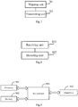
Fig.2 is a flow chart of a method for transmitting data according to an embodiment of the invention; -
Fig.3a is a schematic diagram of a particular implementation of 3-data transmission according to an embodiment of the invention; -
Fig.3b is a schematic diagram of a particular implementation of 3-data transmission in an LTE system according to an embodiment of the invention; -
Fig.3c is a schematic diagram of 2-data transmission according to an embodiment of the invention; -
Fig.4 is a schematic diagram of 5-data transmission according to an embodiment of the invention; -
Fig.5 is a flow chart of a method for receiving and detecting data according to an embodiment of the invention; -
Fig.6 is a schematic structural diagram of a base station according to an embodiment of the invention; -
Fig.7 is a schematic diagram of a user equipment according to an embodiment of the invention; -
Fig.8 is a schematic diagram of a user equipment according to an embodiment of the invention; -
Fig.9 is a schematic structural diagram of a base station according to an embodiment of the invention; and -
Fig.10 is a schematic structural diagram of a user equipment according to an embodiment of the invention. - Embodiments of the invention provide a method for transmitting data, a method for receiving and detecting data, a base station, and a user equipment, in a non-orthogonal mode. When transmitting data, the base station firstly maps plurality pieces of data onto physical resources by multiplying the data with weights, and/or conjugating the data, wherein the number of physical resources is no more than the number of pieces of data, each piece of data is mapped onto at least one of the physical resources, and the number of physical resources onto which each piece of data is mapped is not exactly the same as each other, and the base station then transmits the data over the physical resources, so that more data are transmitted over less physical resources to thereby improve the data transmission capacity of the communication system.
- As illustrated in
Fig.2 , a method for transmitting data according to an embodiment of the invention includes: - The step S201 is to map multiples pieces of data onto physical resources by multiplying the data with weights, and/or conjugating the data, wherein the number of physical resources is no more than the number of pieces of data, each piece of data is mapped onto at least one of the physical resources, and the number of physical resources onto which each piece of data is mapped is not exactly the same as each other; and
- The step S202 is to transmit the data over the physical resources.
- Since the number of physical resources over which the data are transmitted is less than the number of pieces of data, the data transmission capacity of the communication system can be improved.
- With power control, the number of pieces of data transmitted over each physical resource can be more than the number of physical resources, but in order to avoid the resources from being wasted, the number of pieces of data mapped onto each physical resource is no more than the number of physical resources.
- Preferably the data over the same physical resource can be transmitted by superimposition, that is, the data mapped onto the same physical resource are superimposed and then transmitted, where the data are superimposed linearly.
- Preferably, when pieces of data are mapped, they can be divided into multiple layers, and data in different layers are multiplied with different weights, where the weight of the preceding layer is more than the weight of the succeeding layer, and the different data in the same layer are multiplied with the same weight; and/or conjugating data in each layer, where the number of physical resources onto which each piece of data in the preceding layer is mapped is larger than the number of physical resources onto which each piece of data in the succeeding layer is mapped. Furthermore the different data divided into the same layer may be mapped onto the same number of physical resources.
- Furthermore the pieces of data may belong to the same user, or may belong to at least two users.
- If the pieces of data belong to at least two users, then the base station will firstly divide N pieces of data of the at least two users into K layers; and then transmit the N pieces of data over a total number M of uncorrelated physical resources, where N>M; and each piece of data in the same layer is transmitted over the same number of uncorrelated physical resources, and the number of uncorrelated physical resources over which each piece of data in the layer is transmitted is larger than the number of uncorrelated physical resources over which each piece of data in the succeeding layer is transmitted.
- The base station divides the N pieces of data of the users into M physical resources, and transmits the data over the M physical resources, and multiplies the data in different layers with different weights, where the weight of the preceding layer is more than the weight of the succeeding layer, and different data in the same layer are multiplied with the same weight; and/or conjugates data in each layer, where transmission diversity order of data in the succeeding layer is less than transmission diversity order of data in the preceding layer, and the diversity order of a data stream based upon successive interference cancellation receiver is the lowest in the first layer, and thereafter incrementing layer by layer. In the transmission solution according to the embodiment of the invention, the transmission diversity order of the data in the succeeding layer is less than the transmission diversity order of the data in the preceding layer, and the transmission diversity order of the data in the first layer is largest, so that the diversity order of data in each layer detected by successive interference cancellation receiver can be approximate to each other for the users to parse the data for their own data.
- Here the transmission diversity order refers to the number of uncorrelated physical resources over which the data are transmitted. Data carried over two uncorrelated physical resources are uncorrelated; and if multiple pieces of data are carried over the same physical resource, then these pieces of data will be correlated. Typically multiple pieces of data are superimposed linearly and transmitted over the same physical resource.
- With power control, the number of pieces of data transmitted over each physical resource can be more than M, that is, K can be more than M, but if K>M, then the resource may tend to be unnecessarily wasted. Typically if K is less than or equal to M, then the UE can parse the data for its own data. So, preferably the base station transmits not more than M pieces of data over each physical resource.
- Preferably the base station can transmit the M pieces of data over all physical resources at some granularity to thereby alleviate the resources from being wasted, and also enable the respective users to parse accurately the data for their own data.
- At receiving end, a signal is detected with successive interference cancellation reception mode. The reception diversity order of a data stream in the i-th layer based upon successive interference cancellation receiver is:

- Where NR represents the sum of the transmission diversity order and the number of reception antennas of the data, and NT represents the number of transmission antennas of the data.
- With detection based upon successive interference cancellation, the diversity order, brought in by detection, of the first layer of data detected by successive interference cancellation is the lowest, and the diversity order of the succeeding layer of detected data is the diversity order of the preceding layer of detected data plus 1. As can be apparent, the system performance of a receiver based on successive interference cancellation is determined by the accuracy of interference cancellation in the first layer. Hereupon an embodiment of the invention provides a transmission solution in a non-orthogonal joint design under such a general transmission principle that the transmission diversity order of the data in the preceding layer is more than the transmission diversity order of the data in the succeeding layer so that the diversity order of data in each layer as a result of successive interference cancellation can be approximate to each other.
- Data streams can be mapped onto physical resources uncorrelated in one of the frequency, space, time, and other dimensions, or can be mapped onto physical resources uncorrelated in any two of the dimensions, or can be mapped onto physical resources uncorrelated in any more than two of the dimensions.
- By way of an example of three users, and two uncorrelated physical resources, their data are transmitted as follows as illustrated in
Fig.3a :
- Where α 1 represents a power allocation factor of a
user 1, α 2 represents a power allocation factor of auser 2, α 3 represents a power allocation factor of auser 3, and so on until αn represents a power allocation factor of a user n. - The values of the power allocation factors are determined with such a general principle that a signal to noise ratio in each layer as a result of detection by successive interference cancellation receiver is the same or substantially the same.
- s 1 transmitted by the
user 1 for the first time is uncorrelated in time, frequency, or space with s 1 transmitted for the second time so that it can be provided with 2 diversity orders at the receiver. For the 1*2 Single Input Multiple Output (SIMO) system, the diversity order of the symbol s 1 of theuser 1 is 2, so it will be the mostly reliable, and the first to detect, where the diversity of the signal s 1 as a result of detection by successive interference cancellation receiver is:
- After the first symbol s 1 is detected, the detected diversity orders of data s 2 and s 3 of the
user 2 and theuser 3 are:
- For a multi-data stream system, if the reception diversity order of each data stream is the same, then the transmit mode of each data stream is relatively reliable, and the same will apply to a system with more than two data streams.
- Taking the LTE system as an example, if data streams need to be transmitted as described above, then they can be transmitted as illustrated in
Fig.3b where the ordinate represents the frequency, and the abscissa represents the time; and data of theuser 1 and theuser 2 are transmitted in the first frequency area, and the data of theuser 1 and theuser 3 are transmitted in the second frequency area. - As illustrated in
Fig.3c , two pieces of data can also be transmitted over two orthogonal physical resources, and at this time, theuser 2 can transmit two pieces of data S2 and S2' respectively over two orthogonal physical resources. - If there are five users and three orthogonal physical resources, then their data can be preferably transmitted as illustrated in
Fig.4 as follows:
- Where s 1 represents data of the
user 1, s 2 represents data of theuser 2, s 3 represents data of theuser 3, s 4 represents data of theuser 4, s 5 represents data of the user 5, and so on until sn represents data of the user n. - That is, the data of the first, second, and fifth users are transmitted over the first physical resource, the data of the first, second, and third users are transmitted over the second physical resource, and the data of the first, third, and fourth users are transmitted over the third physical resource; and there is such a relationship among the transmission diversity orders of the data of respective users that the
user 1 > theuser 2 = theuser 3 > theuser 4 = the user 5. If both the number of transmission antennas and the number of reception antennas are 3, then the reception diversity orders of respective users will be:


- Transmission of the data as illustrated in
Fig.4 can also be represented in the matrix of:
- If N pieces of data are transmitted over a total number M of uncorrelated physical resources, then the base station can transmit the data as follows:

- Where s1 to sN represent the N pieces of data respectively, and

- Preferably the data can be layered and transmitted as follows:

- Where the row weight refers to the number of 1's in the row, and the row weight is equal to the number of physical resources over which the corresponding data transmitted; and at this time n1 > n 2 = n 3 ≥ ··· ≥ nN. αi ·Si represents the product of αi and Si .
- Alternatively with K=M, the data can be transmitted as represented in the M-dimension square matrix, where if N is an even number, then


- At this time the sum of the first row of data can be transmitted over the first physical resource: α 1· s 1 + α 2 · s 2 + α 4 · s 4 + ...... + αN · sN ;
- The sum of the second row of data can be transmitted over the second physical resource: α 3 · s 3 + α 1 · s 1 + α 2 · s 2 + ...... + α N-2·s N-2;
......; and - The sum of the M-th row of data can be transmitted over the M-th physical resource: α N-1 ·s N-1 + ...... + α5 ·s 5 + α 3 · s 3 + α 1 · s 1;
- Or
- The sum of the first column of data can be transmitted over the first physical resource: α 1 · s 1 + α 3 · s 3 + α 5 · s 5 + ...... + α N-1 · s N-1;
- The sum of the second column of data can be transmitted over the second physical resource: α 2 · s 2 + α 1 · s 1 + α 3 · s 3 + ...... + α N-3 · s N-3;
......; and - The sum of the M-th column of data can be transmitted over the M-th physical resource: αN · s N + ...... + α 4 · s 4 + α 2 · s 2 + α 1 · s 1;
- An embodiment of the invention further provides a corresponding method for receiving and detecting data as illustrated in
Fig.5 , where the method includes: - In the step S501, a UE receives data transmitted by a base station over multiple physical resources; and
- In the step S502, the UE detects the data mapped onto the multiple physical resources according to mapping mode, where the number of pieces of data mapped onto the physical resources is no less than the number of physical resources, each piece of data is mapped onto at least one of the physical resources, and the number of physical resources onto which each piece of data is mapped is not exactly the same as each other.
- With power control, the number of pieces of data transmitted over each physical resource can be more than the number of physical resources, but in order to avoid the resources from being wasted, the number of pieces of data mapped onto each physical resource is no more than the number of physical resources.
- Preferably the data over the same physical resource can be transmitted by superimposing the data, that is, the data mapped onto the same physical resource are superimposed and then transmitted, where the data are superimposed linearly.
- Preferably, when pieces of data is mapped, the pieces of data is conjugated, and divided into multiple layers, and data in different layers are multiplied with different weights, where the weight of the preceding layer is more than the weight of the succeeding layer, and the number of physical resources onto which each piece of data in the preceding layer is mapped is larger than the number of physical resources onto which each piece of data in the succeeding layer is mapped. Furthermore the different data divided into the same layer may be mapped onto the same number of physical resources.
- Furthermore the pieces of data may belong to the same user, or may belong to at least two users, and the UE can detect the data for its own data.
- Preferably the UE detects the data via the way of successive interference cancellation. The successive interference cancellation technology is generally that the data in respective layers are detected in sequence, and a detection result of the preceding layer is used for cancelling interference in the succeeding layer, so that data in the succeeding layer is detected with the result of cancelling the interference of data in the preceding layer.
- Furthermore the UE preferentially detects the data in such a layer that each piece of data is mapped onto the larger number of physical resources.
- An embodiment of the invention provides a particular method for receiving and detecting data as illustrated in
Fig.6 , where the method includes: - In the step S601, a UE receives multiple pieces of data transmitted by a base station over physical resources with the number thereof is smaller than the number of pieces of data, where each piece of data is mapped onto at least one of the physical resources, and the number of physical resources onto which respective pieces of data is mapped is not exactly the same; and
- In the step S602, the UE detects data in respective layers in sequence starting with the first layer by the way of successive interference cancellation until the UE detects the data for its own data.
- Preferably particularly in the step S601, the UE receives N pieces of data transmitted to at least two users by the base station over M orthogonal physical resources, where M<N and:
- The N pieces of data are divided into K layers, and transmitted over a total number M of uncorrelated physical resources; and each piece of data in the same layer is transmitted over the same number of uncorrelated physical resources, and the number of uncorrelated physical resources over which each piece of data in the layer is transmitted is larger than the number of uncorrelated physical resources over which each piece of data in the succeeding layer is transmitted.
- If the data in respective layers are detected in sequence starting with the first layer, then the average calculation complexity of respective users will be lower.
- Still taking as an example three users and two orthogonal physical resources as illustrated in
Fig.3a , theuser 1 receives the following signals:

- Where h 11 represents a channel matrix traversed by the first half of symbol, and h 12 represents a channel matrix traversed by the second half of symbol.
- s 2 and s 3 are regarded as interference signals and detected as follows:
- The first step is to normalize the received signals:


- The second step is to detect LLR 1 (s 1) and LLR 2(s 1) respectively by the receiver with the Minimum Mean Square Error (MMSE) algorithm.

- The user 2 (a low-diversity order user) receives the following signals:


- Firstly s 1 is detected for ŝ 1, then ŝ 1 is cancelled from ŝ, and next s 2 and s 3 are detected.
- The first step is to normalize the received signals:


- The second step is to let
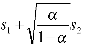


- LLR 1(T(1)) + LLR 2(T(2)) is detected softly for ŝ 1;
- The third step is to decode LLR values of softly detected ŝ 1 so that the signals of the
user 1 are detected so accurately that there is approximately no error in a result after decoding, and to softly modulate the result after decoding into a softly modulated symbol; and
- The fourth step is to cancel interference ofresulting inand ŝ 3:
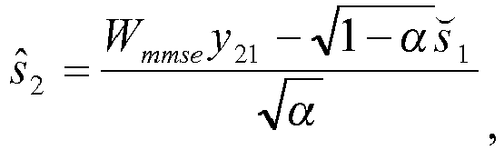

- The same detection flow applies to the third user.
- An embodiment of the invention further provides a corresponding base station as illustrated in
Fig.7 , where the base station includes: - A
mapping unit 701 is configured to map multiples pieces of data onto physical resources by multiplying the data with weights, and/or conjugating the data, wherein the number of physical resources is no more than the number of pieces of data, each piece of data is mapped onto at least one of the physical resources, and the number of physical resources onto which each piece of data is mapped is not exactly the same as each other; and - A transmitting
unit 702 is configured to transmit the data over the physical resources. - Preferably the number of pieces of data mapped onto each physical resource is no more than the number of physical resources.
- Preferably the data mapped onto the same physical resource are superimposed and then transmitted.
- Furthermore the data are superimposed linearly.
- Preferably the pieces of data are divided into multiple layers, where the number of physical resources onto which each piece of data in the preceding layer is mapped is larger than the number of physical resources onto which each piece of data in the succeeding layer is mapped.
- Furthermore the data in different layers are multiplied with different weights, where the weight of the preceding layer is more than the weight of the succeeding layer, and the different data in the same layer are multiplied with the same weight; and/or data in each layer are conjugated.
- Preferably the different data divided into the same layer are mapped onto the same number of physical resources.
- Furthermore the pieces of data belong to at least two users.
- An embodiment of the invention further provides a user equipment as illustrated in
Fig.8 , where the user equipment includes: - A receiving
unit 801 is configured to receive data transmitted by a base station over multiple physical resources; and - A detecting
unit 802 is configured to detect the data mapped onto the multiple physical resources according to mapping mode, where the number of pieces of data mapped onto the physical resources is no less than the number of physical resources, each piece of data is mapped onto at least one of the physical resources, and the number of physical resources onto which each piece of data is mapped is not exactly the same as each other. - Preferably the number of pieces of data mapped onto each physical resource is no more than the number of physical resources.
- Preferably the data mapped onto the same physical resource are multiplied with the same weight, and superimposed and then transmitted.
- Furthermore the data are superimposed linearly.
- Preferably the pieces of data are divided into multiple layers, where the number of physical resources onto which each piece of data in the preceding layer is mapped is larger than the number of physical resources onto which each piece of data in the succeeding layer is mapped.
- Preferably the different data divided into the same layer are mapped onto the same number of physical resources.
- Preferably the pieces of data belong to at least two users, and the UE detects the data for its own data.
- Furthermore the UE detects data by the way of successive interference cancellation.
- Still furthermore the UE preferentially detects data in such a layer that each piece of data is mapped onto the larger number of physical resources.
- An embodiment of the invention further provides a base station including:
- A processor is configured to map multiples pieces of data onto physical resources by multiplying the data with weights, and/or conjugating the data, wherein the number of physical resources is no more than the number of pieces of data, each piece of data is mapped onto at least one of the physical resources, and the number of physical resources onto which each piece of data is mapped is not exactly the same as each other; and to transmit the data over the physical resources.
- The base station can be further configured to perform the other functions in the method for transmitting data according to the embodiment of the invention.
- The base station can transmit the data through a transceiver module and a radio interface.
- An embodiment of the invention further provides a user equipment including:
- A processor is configured to receive data transmitted by a base station over multiple physical resources; and to detect the data mapped onto the multiple physical resources according to mapping mode, where the number of pieces of data mapped onto the physical resources is no less than the number of physical resources, each piece of data is mapped onto at least one of the physical resources, and the number of physical resources onto which each piece of data is mapped is not exactly the same as each other.
- The user equipment can be further configured to perform the other functions in the method for receiving and detecting data according to the embodiment of the invention.
- The user equipment can receive the data through a transceiver module and a radio interface.
- Based upon the same inventive concept as the method, an embodiment of the invention further provides a base station as illustrated in
Fig.9 , where the base station includes: - A
transceiver 903, aprocessor 901, amemory 902, and abus interface 904, where theprocessor 901 and thememory 902 are connected with thetransceiver 903 via thebus interface 904. - The
processor 901 is configured with one or more executable programs configured to perform a method including: mapping multiples pieces of data onto physical resources by multiplying the data with weights, and/or conjugating the data, wherein the number of physical resources is no more than the number of pieces of data, each piece of data is mapped onto at least one of the physical resources, and the number of physical resources onto which each piece of data is mapped is not exactly the same as each other;
Thetransceiver 903 is configured to transmit the data over the physical resources;
Thememory 902 is configured to store the one or more executable programs for configuring theprocessor 901; and
Thebus interface 904 is configured to serve as an interface, theprocessor 901 is responsible for managing the bus architecture and performing other normal processes, and thememory 902 can be configured to store data for use by theprocessor 901 in operation. - The bus architecture can include any number of interconnected buses and bridges to link together various circuits including one or more processors represented by the processor, and one or more memories represented by the memory. The bus architecture can further link together various other circuits, e.g., peripheral devices, a voltage stabilizer, a power management circuit, etc., and all of these circuits are well known in the art, so a further description thereof will be omitted in this context.
- Based upon the same inventive concept as the method, an embodiment of the invention further provides a base station as illustrated in
Fig.10 , where the base station includes: - A
transceiver 1003, a processor 1001, amemory 1002, and abus interface 1004, where the processor 1001 and thememory 1002 are connected with thetransceiver 1003 via thebus interface 1004. - The
transceiver 1003 is configured to receive data transmitted by a base station over multiple physical resources; - The processor 1001 is configured with one or more executable programs configured to perform a method including: detecting the data mapped onto the multiple physical resources according to mapping mode, where the number of pieces of data mapped onto the physical resources is no less than the number of physical resources, each piece of data is mapped onto at least one of the physical resources, and the number of physical resources onto which each piece of data is mapped is not exactly the same as each other; and the pieces of data are divided into multiple layers, data in different layers are multiplied with different weights, and the weight of the preceding layer is more than the weight of the succeeding layer, and different data in the same layer are multiplied with the same weight; and/or data in each layer are conjugated.
- The
memory 1002 is configured to store the one or more executable programs for configuring the processor 1001; and
Thebus interface 1004 is configured to serve as an interface, the processor 1001 is responsible for managing the bus architecture and performing other normal processes, and thememory 1002 can be configured to store data for use by the processor 1001 in operation. - The bus architecture can include any number of interconnected buses and bridges to link together various circuits including one or more processors represented by the processor, and one or more memories represented by the memory. The bus architecture can further link together various other circuits, e.g., peripheral devices, a voltage stabilizer, a power management circuit, etc., and all of these circuits are well known in the art, so a further description thereof will be omitted in this context.
- The embodiments of the invention provide a method for transmitting data, a method for receiving and detecting data, a base station, and a user equipment, in a non-orthogonal mode. When transmitting data, the base station firstly maps plurality pieces of data onto physical resources by multiplying the data with weights, and/or conjugating the data, the number of physical resources is no more than the number of pieces of data, each piece of data is mapped onto at least one of the physical resources, and the number of physical resources onto which each piece of data is mapped is not exactly the same as each other, and the base station then transmits the data over the physical resources, so that more data are transmitted over less physical resources to thereby improve the data transmission capacity of the communication system.
- Those skilled in the art shall appreciate that the embodiments of the invention can be embodied as a method, a system or a computer program product. Therefore the invention can be embodied in the form of an all-hardware embodiment, an all-software embodiment or an embodiment of software and hardware in combination. Furthermore the invention can be embodied in the form of a computer program product embodied in one or more computer useable storage mediums (including but not limited to a disk memory, a CD-ROM, an optical memory, etc.) in which computer useable program codes are contained.
- The invention has been described in a flow chart and/or a block diagram of the method, the device (system) and the computer program product according to the embodiments of the invention. It shall be appreciated that respective flows and/or blocks in the flow chart and/or the block diagram and combinations of the flows and/or the blocks in the flow chart and/or the block diagram can be embodied in computer program instructions. These computer program instructions can be loaded onto a general-purpose computer, a specific-purpose computer, an embedded processor or a processor of another programmable data processing device to produce a machine so that the instructions executed on the computer or the processor of the other programmable data processing device create means for performing the functions specified in the flow(s) of the flow chart and/or the block(s) of the block diagram.
- These computer program instructions can also be stored into a computer readable memory capable of directing the computer or the other programmable data processing device to operate in a specific manner so that the instructions stored in the computer readable memory create an article of manufacture including instruction means which perform the functions specified in the flow(s) of the flow chart and/or the block(s) of the block diagram.
- These computer program instructions can also be loaded onto the computer or the other programmable data processing device so that a series of operational steps are performed on the computer or the other programmable data processing device to create a computer implemented process so that the instructions executed on the computer or the other programmable device provide steps for performing the functions specified in the flow(s) of the flow chart and/or the block(s) of the block diagram.
- Although the preferred embodiments of the invention have been described, those skilled in the art benefiting from the underlying inventive concept can make additional modifications and variations to these embodiments. Therefore the appended claims are intended to be construed as encompassing the preferred embodiments and all the modifications and variations coming into the scope of the invention.
- Evidently those skilled in the art can make various modifications and variations to the invention without departing from the spirit and scope of the invention. Thus the invention is also intended to encompass these modifications and variations thereto so long as the modifications and variations come into the scope of the claims appended to the invention and their equivalents.
Claims (25)
- A method for transmitting data, the method comprising:mapping multiples pieces of data onto physical resources by multiplying the data with weights, and/or conjugating the data, wherein the number of physical resources is no more than the number of pieces of data, each piece of data is mapped onto at least one of the physical resources, and the number of physical resources onto which each piece of data is mapped is not exactly the same as each other; andtransmitting the data over the physical resources.
- The method according to claim 1, wherein the number of pieces of data mapped onto each physical resource is no more than the number of physical resources.
- The method according to claim 2, wherein the data mapped onto the same physical resource are superimposed and then transmitted.
- The method according to claim 3, wherein the data are superimposed linearly.
- The method according to claim 1, wherein the pieces of data are divided into multiple layers, wherein the number of physical resources onto which each piece of data in the preceding layer is mapped is larger than the number of physical resources onto which each piece of data in the succeeding layer is mapped.
- The method according to claim 5, wherein the different data divided into the same layer are mapped onto the same number of physical resources.
- The method according to claim 5, wherein the data in different layers are multiplied with different weights, wherein the weight of the preceding layer is more than the weight of the succeeding layer, and the different data in the same layer are multiplied with the same weight.
- The method according to claim 1, wherein the pieces of data belong to at least two users.
- A method for receiving and detecting data, the method comprising:receiving, by a User Equipment, UE, data transmitted by a base station over multiple physical resources; anddetecting by the UE, the data mapped onto the multiple physical resources according to mapping mode, wherein the number of pieces of data mapped onto the physical resources is no less than the number of physical resources, each piece of data is mapped onto at least one of the physical resources, and the number of physical resources onto which each piece of data is mapped is not exactly the same as each other; and the pieces of data are divided into multiple layers, wherein the data in different layers are multiplied with different weights, the weight of the preceding layer is more than the weight of the succeeding layer, and the different data in the same layer are multiplied with the same weight; and/or data in each layer are conjugated.
- Abase station, comprising:a mapping unit configured to map multiples pieces of data onto physical resources by multiplying the data with weights, and/or conjugating the data, wherein the number of physical resources is no more than the number of pieces of data, each piece of data is mapped onto at least one of the physical resources, and the number of physical resources onto which each piece of data is mapped is not exactly the same as each other; anda transmitting unit configured to transmit the data over the physical resources.
- The base station according to claim 10, wherein the number of pieces of data mapped onto each physical resource is no more than the number of physical resources.
- The base station according to claim 11, wherein the data mapped onto the same physical resource are superimposed and then transmitted.
- The base station according to claim 12, wherein the data are superimposed linearly.
- The base station according to claim 10, wherein the pieces of data are divided into multiple layers, wherein the number of physical resources onto which each piece of data in the preceding layer is mapped is larger than the number of physical resources onto which each piece of data in the succeeding layer is mapped.
- The base station according to claim 14, wherein the different data divided into the same layer are mapped onto the same number of physical resources.
- The base station according to claim 10, wherein the pieces of data belong to at least two users.
- A user equipment, comprising:a receiving unit configured to receive data transmitted by a base station over multiple physical resources; anda detecting unit configured to detect the data mapped onto the multiple physical resources according to mapping mode, wherein the number of pieces of data mapped onto the physical resources is no less than the number of physical resources, each piece of data is mapped onto at least one of the physical resources, and the number of physical resources onto which each piece of data is mapped is not exactly the same as each other; and the pieces of data are divided into multiple layers, wherein the data in different layers are multiplied with different weights, the weight of the preceding layer is more than the weight of the succeeding layer, and the different data in the same layer are multiplied with the same weight; and/or data in each layer are conjugated.
- Abase station, comprising:a transceiver, a processor, a memory, and a bus interface, wherein the processor and the memory are connected with the transceiver through the bus interface;the processor is configured with one or more executable programs configured to perform a method comprising: mapping multiples pieces of data onto physical resources by multiplying the data with weights, and/or conjugating the data, wherein the number of physical resources is no more than the number of pieces of data, each piece of data is mapped onto at least one of the physical resources, and the number of physical resources onto which each piece of data is mapped is not exactly the same as each other;the transceiver is configured to transmit the data over the physical resources;the memory is configured to store the one or more executable programs for configuring the processor; andthe bus interface is configured to serve as an interface.
- The base station according to claim 18, wherein the number of pieces of data mapped onto each physical resource is no more than the number of physical resources.
- The base station according to claim 19, wherein the data mapped onto the same physical resource are superimposed and then transmitted.
- The base station according to claim 20, wherein the data are superimposed linearly.
- The base station according to claim 18, wherein the pieces of data are divided into multiple layers, wherein the number of physical resources onto which each piece of data in the preceding layer is mapped is larger than the number of physical resources onto which each piece of data in the succeeding layer is mapped.
- The base station according to claim 22, wherein the different data divided into the same layer are mapped onto the same number of physical resources.
- The base station according to claim 18, wherein the pieces of data belong to at least two users.
- A user equipment, comprising:a transceiver, a processor, a memory, and a bus interface, wherein the processor and the memory are connected with the transceiver through the bus interface;the transceiver is configured to receive data transmitted by a base station over multiple physical resources;the processor is configured with one or more executable programs configured to perform a method comprising: detecting the data mapped onto the multiple physical resources according to mapping mode, wherein the number of pieces of data mapped onto the physical resources is no less than the number of physical resources, each piece of data is mapped onto at least one of the physical resources, and the number of physical resources onto which each piece of data is mapped is not exactly the same as each other; and the pieces of data are divided into multiple layers, wherein the data in different layers are multiplied with different weights, the weight of the preceding layer is more than the weight of the succeeding layer, and the different data in the same layer are multiplied with the same weight; and/or data in each layer of are conjugated;the memory is configured to store the one or more executable programs for configuring the processor; andthe bus interface is configured to serve as an interface.
Applications Claiming Priority (2)
| Application Number | Priority Date | Filing Date | Title |
|---|---|---|---|
| CN201410067167.XA CN104868983B (en) | 2014-02-26 | 2014-02-26 | A kind of data transfer, data receiver detection method and base station, user equipment |
| PCT/CN2015/073201 WO2015127885A1 (en) | 2014-02-26 | 2015-02-16 | Method for detecting data transmission and data reception, and base station and user device |
Publications (3)
| Publication Number | Publication Date |
|---|---|
| EP3113562A1 true EP3113562A1 (en) | 2017-01-04 |
| EP3113562A4 EP3113562A4 (en) | 2017-03-22 |
| EP3113562B1 EP3113562B1 (en) | 2019-11-13 |
Family
ID=53914531
Family Applications (1)
| Application Number | Title | Priority Date | Filing Date |
|---|---|---|---|
| EP15755110.2A Active EP3113562B1 (en) | 2014-02-26 | 2015-02-16 | Method, base station and radio communication system for superimposed data transmission |
Country Status (6)
| Country | Link |
|---|---|
| US (1) | US10028287B2 (en) |
| EP (1) | EP3113562B1 (en) |
| JP (1) | JP2017512425A (en) |
| KR (2) | KR102038078B1 (en) |
| CN (1) | CN104868983B (en) |
| WO (1) | WO2015127885A1 (en) |
Families Citing this family (2)
| Publication number | Priority date | Publication date | Assignee | Title |
|---|---|---|---|---|
| CN107508661B (en) * | 2016-06-14 | 2020-07-21 | 华为技术有限公司 | Data processing method, network equipment and terminal |
| KR20230157547A (en) | 2022-05-09 | 2023-11-17 | 삼성디스플레이 주식회사 | Display device |
Family Cites Families (8)
| Publication number | Priority date | Publication date | Assignee | Title |
|---|---|---|---|---|
| US8085819B2 (en) * | 2006-04-24 | 2011-12-27 | Qualcomm Incorporated | Superposition coding in a wireless communication system |
| CN101433005A (en) * | 2006-04-24 | 2009-05-13 | 高通股份有限公司 | Overlapping Coding in Wireless Communication Systems |
| EP2057855B1 (en) * | 2006-08-29 | 2009-12-09 | Telefonaktiebolaget L M Ericsson (Publ) | Detection of access bursts in a random access channel |
| US7869539B2 (en) * | 2007-01-08 | 2011-01-11 | The Mitre Corporation | Methods, systems, and computer program products for rateless coding |
| JP5864200B2 (en) * | 2011-05-20 | 2016-02-17 | 株式会社Nttドコモ | Receiving device, transmitting device, and wireless communication method |
| JP5785845B2 (en) * | 2011-05-20 | 2015-09-30 | 株式会社Nttドコモ | Receiving device, transmitting device, and wireless communication method |
| JP5864199B2 (en) * | 2011-05-20 | 2016-02-17 | 株式会社Nttドコモ | Receiving device, transmitting device, and wireless communication method |
| JP6050028B2 (en) * | 2012-05-25 | 2016-12-21 | シャープ株式会社 | Terminal, base station, communication method and integrated circuit |
-
2014
- 2014-02-26 CN CN201410067167.XA patent/CN104868983B/en active Active
-
2015
- 2015-02-16 WO PCT/CN2015/073201 patent/WO2015127885A1/en not_active Ceased
- 2015-02-16 JP JP2016554332A patent/JP2017512425A/en active Pending
- 2015-02-16 KR KR1020197002909A patent/KR102038078B1/en active Active
- 2015-02-16 EP EP15755110.2A patent/EP3113562B1/en active Active
- 2015-02-16 KR KR1020167026510A patent/KR20160127082A/en not_active Ceased
- 2015-02-16 US US15/121,367 patent/US10028287B2/en active Active
Also Published As
| Publication number | Publication date |
|---|---|
| WO2015127885A1 (en) | 2015-09-03 |
| EP3113562A4 (en) | 2017-03-22 |
| CN104868983A (en) | 2015-08-26 |
| EP3113562B1 (en) | 2019-11-13 |
| KR102038078B1 (en) | 2019-10-29 |
| JP2017512425A (en) | 2017-05-18 |
| KR20160127082A (en) | 2016-11-02 |
| KR20190012282A (en) | 2019-02-08 |
| US20170265199A1 (en) | 2017-09-14 |
| CN104868983B (en) | 2018-03-27 |
| US10028287B2 (en) | 2018-07-17 |
Similar Documents
| Publication | Publication Date | Title |
|---|---|---|
| US10355883B2 (en) | Signal detection method and signal detection device | |
| CN106452697A (en) | Sending method and apparatus, and receiving method and apparatus of uplink data | |
| US11228930B2 (en) | Method, device and apparatus for selecting user signature vector, and storage medium | |
| EP3236634B1 (en) | Method and device for configuring and determining a code superposition-based multiuser encoding mode | |
| US20160080063A1 (en) | Communication system and communication control method | |
| US10230445B2 (en) | Data transmission method, data reception method, data transmission device and data reception device | |
| US10181935B2 (en) | Pilot configuration method and apparatus | |
| US9510304B2 (en) | Method and apparatus for implementing primary synchronization signal in time domain and computer storage medium | |
| CN107078836B (en) | A method and device for generating a pilot signal | |
| CN104488214A (en) | Method and apparatus for jointly performing channel estimation and interference estimation in a wireless communication system | |
| EP3113562B1 (en) | Method, base station and radio communication system for superimposed data transmission | |
| CN103634071A (en) | Pre-coding matrix selection method, device and system | |
| US20210083826A1 (en) | Data transmission method and apparatus and computer storage medium | |
| EP2611044A2 (en) | Adaptive transmit beamforming | |
| EP4447368A1 (en) | Method and apparatus for simultaneous transmission of uplink sounding reference signal for user equipment | |
| CN102148779B (en) | Method and device for detecting signals | |
| US20190173531A1 (en) | Multi-cell coordination system and method | |
| US10014995B2 (en) | Data transmission method, data reception and detection method, base station and user equipment | |
| CN105262560A (en) | Signal transmission method and device | |
| US20260059500A1 (en) | Signal transmission method and apparatus, terminal, and storage medium | |
| JP5770861B2 (en) | Power allocation in a wireless system where the base station has an antenna array | |
| CN108418654B (en) | Signal detection method and device |
Legal Events
| Date | Code | Title | Description |
|---|---|---|---|
| STAA | Information on the status of an ep patent application or granted ep patent |
Free format text: STATUS: THE INTERNATIONAL PUBLICATION HAS BEEN MADE |
|
| PUAI | Public reference made under article 153(3) epc to a published international application that has entered the european phase |
Free format text: ORIGINAL CODE: 0009012 |
|
| STAA | Information on the status of an ep patent application or granted ep patent |
Free format text: STATUS: REQUEST FOR EXAMINATION WAS MADE |
|
| 17P | Request for examination filed |
Effective date: 20160902 |
|
| AK | Designated contracting states |
Kind code of ref document: A1 Designated state(s): AL AT BE BG CH CY CZ DE DK EE ES FI FR GB GR HR HU IE IS IT LI LT LU LV MC MK MT NL NO PL PT RO RS SE SI SK SM TR |
|
| AX | Request for extension of the european patent |
Extension state: BA ME |
|
| REG | Reference to a national code |
Ref country code: DE Ref legal event code: R079 Ref document number: 602015041674 Country of ref document: DE Free format text: PREVIOUS MAIN CLASS: H04W0072040000 Ipc: H04L0005000000 |
|
| A4 | Supplementary search report drawn up and despatched |
Effective date: 20170216 |
|
| RIC1 | Information provided on ipc code assigned before grant |
Ipc: H04L 5/00 20060101AFI20170210BHEP |
|
| DAX | Request for extension of the european patent (deleted) | ||
| STAA | Information on the status of an ep patent application or granted ep patent |
Free format text: STATUS: EXAMINATION IS IN PROGRESS |
|
| 17Q | First examination report despatched |
Effective date: 20180117 |
|
| GRAP | Despatch of communication of intention to grant a patent |
Free format text: ORIGINAL CODE: EPIDOSNIGR1 |
|
| STAA | Information on the status of an ep patent application or granted ep patent |
Free format text: STATUS: GRANT OF PATENT IS INTENDED |
|
| INTG | Intention to grant announced |
Effective date: 20190627 |
|
| GRAS | Grant fee paid |
Free format text: ORIGINAL CODE: EPIDOSNIGR3 |
|
| GRAA | (expected) grant |
Free format text: ORIGINAL CODE: 0009210 |
|
| STAA | Information on the status of an ep patent application or granted ep patent |
Free format text: STATUS: THE PATENT HAS BEEN GRANTED |
|
| AK | Designated contracting states |
Kind code of ref document: B1 Designated state(s): AL AT BE BG CH CY CZ DE DK EE ES FI FR GB GR HR HU IE IS IT LI LT LU LV MC MK MT NL NO PL PT RO RS SE SI SK SM TR |
|
| REG | Reference to a national code |
Ref country code: AT Ref legal event code: REF Ref document number: 1202798 Country of ref document: AT Kind code of ref document: T Effective date: 20191115 Ref country code: CH Ref legal event code: EP |
|
| REG | Reference to a national code |
Ref country code: DE Ref legal event code: R096 Ref document number: 602015041674 Country of ref document: DE |
|
| REG | Reference to a national code |
Ref country code: IE Ref legal event code: FG4D |
|
| REG | Reference to a national code |
Ref country code: NL Ref legal event code: MP Effective date: 20191113 |
|
| REG | Reference to a national code |
Ref country code: LT Ref legal event code: MG4D |
|
| PG25 | Lapsed in a contracting state [announced via postgrant information from national office to epo] |
Ref country code: GR Free format text: LAPSE BECAUSE OF FAILURE TO SUBMIT A TRANSLATION OF THE DESCRIPTION OR TO PAY THE FEE WITHIN THE PRESCRIBED TIME-LIMIT Effective date: 20200214 Ref country code: PL Free format text: LAPSE BECAUSE OF FAILURE TO SUBMIT A TRANSLATION OF THE DESCRIPTION OR TO PAY THE FEE WITHIN THE PRESCRIBED TIME-LIMIT Effective date: 20191113 Ref country code: NO Free format text: LAPSE BECAUSE OF FAILURE TO SUBMIT A TRANSLATION OF THE DESCRIPTION OR TO PAY THE FEE WITHIN THE PRESCRIBED TIME-LIMIT Effective date: 20200213 Ref country code: LT Free format text: LAPSE BECAUSE OF FAILURE TO SUBMIT A TRANSLATION OF THE DESCRIPTION OR TO PAY THE FEE WITHIN THE PRESCRIBED TIME-LIMIT Effective date: 20191113 Ref country code: BG Free format text: LAPSE BECAUSE OF FAILURE TO SUBMIT A TRANSLATION OF THE DESCRIPTION OR TO PAY THE FEE WITHIN THE PRESCRIBED TIME-LIMIT Effective date: 20200213 Ref country code: FI Free format text: LAPSE BECAUSE OF FAILURE TO SUBMIT A TRANSLATION OF THE DESCRIPTION OR TO PAY THE FEE WITHIN THE PRESCRIBED TIME-LIMIT Effective date: 20191113 Ref country code: NL Free format text: LAPSE BECAUSE OF FAILURE TO SUBMIT A TRANSLATION OF THE DESCRIPTION OR TO PAY THE FEE WITHIN THE PRESCRIBED TIME-LIMIT Effective date: 20191113 Ref country code: SE Free format text: LAPSE BECAUSE OF FAILURE TO SUBMIT A TRANSLATION OF THE DESCRIPTION OR TO PAY THE FEE WITHIN THE PRESCRIBED TIME-LIMIT Effective date: 20191113 Ref country code: LV Free format text: LAPSE BECAUSE OF FAILURE TO SUBMIT A TRANSLATION OF THE DESCRIPTION OR TO PAY THE FEE WITHIN THE PRESCRIBED TIME-LIMIT Effective date: 20191113 Ref country code: PT Free format text: LAPSE BECAUSE OF FAILURE TO SUBMIT A TRANSLATION OF THE DESCRIPTION OR TO PAY THE FEE WITHIN THE PRESCRIBED TIME-LIMIT Effective date: 20200313 |
|
| PG25 | Lapsed in a contracting state [announced via postgrant information from national office to epo] |
Ref country code: IS Free format text: LAPSE BECAUSE OF FAILURE TO SUBMIT A TRANSLATION OF THE DESCRIPTION OR TO PAY THE FEE WITHIN THE PRESCRIBED TIME-LIMIT Effective date: 20200313 Ref country code: HR Free format text: LAPSE BECAUSE OF FAILURE TO SUBMIT A TRANSLATION OF THE DESCRIPTION OR TO PAY THE FEE WITHIN THE PRESCRIBED TIME-LIMIT Effective date: 20191113 Ref country code: RS Free format text: LAPSE BECAUSE OF FAILURE TO SUBMIT A TRANSLATION OF THE DESCRIPTION OR TO PAY THE FEE WITHIN THE PRESCRIBED TIME-LIMIT Effective date: 20191113 |
|
| PG25 | Lapsed in a contracting state [announced via postgrant information from national office to epo] |
Ref country code: AL Free format text: LAPSE BECAUSE OF FAILURE TO SUBMIT A TRANSLATION OF THE DESCRIPTION OR TO PAY THE FEE WITHIN THE PRESCRIBED TIME-LIMIT Effective date: 20191113 |
|
| PG25 | Lapsed in a contracting state [announced via postgrant information from national office to epo] |
Ref country code: DK Free format text: LAPSE BECAUSE OF FAILURE TO SUBMIT A TRANSLATION OF THE DESCRIPTION OR TO PAY THE FEE WITHIN THE PRESCRIBED TIME-LIMIT Effective date: 20191113 Ref country code: EE Free format text: LAPSE BECAUSE OF FAILURE TO SUBMIT A TRANSLATION OF THE DESCRIPTION OR TO PAY THE FEE WITHIN THE PRESCRIBED TIME-LIMIT Effective date: 20191113 Ref country code: ES Free format text: LAPSE BECAUSE OF FAILURE TO SUBMIT A TRANSLATION OF THE DESCRIPTION OR TO PAY THE FEE WITHIN THE PRESCRIBED TIME-LIMIT Effective date: 20191113 Ref country code: CZ Free format text: LAPSE BECAUSE OF FAILURE TO SUBMIT A TRANSLATION OF THE DESCRIPTION OR TO PAY THE FEE WITHIN THE PRESCRIBED TIME-LIMIT Effective date: 20191113 Ref country code: RO Free format text: LAPSE BECAUSE OF FAILURE TO SUBMIT A TRANSLATION OF THE DESCRIPTION OR TO PAY THE FEE WITHIN THE PRESCRIBED TIME-LIMIT Effective date: 20191113 |
|
| REG | Reference to a national code |
Ref country code: DE Ref legal event code: R097 Ref document number: 602015041674 Country of ref document: DE |
|
| REG | Reference to a national code |
Ref country code: AT Ref legal event code: MK05 Ref document number: 1202798 Country of ref document: AT Kind code of ref document: T Effective date: 20191113 |
|
| PG25 | Lapsed in a contracting state [announced via postgrant information from national office to epo] |
Ref country code: SK Free format text: LAPSE BECAUSE OF FAILURE TO SUBMIT A TRANSLATION OF THE DESCRIPTION OR TO PAY THE FEE WITHIN THE PRESCRIBED TIME-LIMIT Effective date: 20191113 Ref country code: SM Free format text: LAPSE BECAUSE OF FAILURE TO SUBMIT A TRANSLATION OF THE DESCRIPTION OR TO PAY THE FEE WITHIN THE PRESCRIBED TIME-LIMIT Effective date: 20191113 |
|
| PLBE | No opposition filed within time limit |
Free format text: ORIGINAL CODE: 0009261 |
|
| STAA | Information on the status of an ep patent application or granted ep patent |
Free format text: STATUS: NO OPPOSITION FILED WITHIN TIME LIMIT |
|
| REG | Reference to a national code |
Ref country code: CH Ref legal event code: PL |
|
| 26N | No opposition filed |
Effective date: 20200814 |
|
| REG | Reference to a national code |
Ref country code: BE Ref legal event code: MM Effective date: 20200229 |
|
| PG25 | Lapsed in a contracting state [announced via postgrant information from national office to epo] |
Ref country code: MC Free format text: LAPSE BECAUSE OF FAILURE TO SUBMIT A TRANSLATION OF THE DESCRIPTION OR TO PAY THE FEE WITHIN THE PRESCRIBED TIME-LIMIT Effective date: 20191113 Ref country code: LU Free format text: LAPSE BECAUSE OF NON-PAYMENT OF DUE FEES Effective date: 20200216 |
|
| PG25 | Lapsed in a contracting state [announced via postgrant information from national office to epo] |
Ref country code: CH Free format text: LAPSE BECAUSE OF NON-PAYMENT OF DUE FEES Effective date: 20200229 Ref country code: AT Free format text: LAPSE BECAUSE OF FAILURE TO SUBMIT A TRANSLATION OF THE DESCRIPTION OR TO PAY THE FEE WITHIN THE PRESCRIBED TIME-LIMIT Effective date: 20191113 Ref country code: LI Free format text: LAPSE BECAUSE OF NON-PAYMENT OF DUE FEES Effective date: 20200229 Ref country code: SI Free format text: LAPSE BECAUSE OF FAILURE TO SUBMIT A TRANSLATION OF THE DESCRIPTION OR TO PAY THE FEE WITHIN THE PRESCRIBED TIME-LIMIT Effective date: 20191113 |
|
| PG25 | Lapsed in a contracting state [announced via postgrant information from national office to epo] |
Ref country code: IE Free format text: LAPSE BECAUSE OF NON-PAYMENT OF DUE FEES Effective date: 20200216 Ref country code: IT Free format text: LAPSE BECAUSE OF FAILURE TO SUBMIT A TRANSLATION OF THE DESCRIPTION OR TO PAY THE FEE WITHIN THE PRESCRIBED TIME-LIMIT Effective date: 20191113 |
|
| PG25 | Lapsed in a contracting state [announced via postgrant information from national office to epo] |
Ref country code: BE Free format text: LAPSE BECAUSE OF NON-PAYMENT OF DUE FEES Effective date: 20200229 |
|
| REG | Reference to a national code |
Ref country code: DE Ref legal event code: R081 Ref document number: 602015041674 Country of ref document: DE Owner name: DATANG MOBILE COMMUNICATIONS EQUIPMENT CO., LT, CN Free format text: FORMER OWNER: CHINA ACADEMY OF TELECOMMUNICATIONS TECHNOLOGY, HAIDIAN, DISTRICT BEIJING, CN |
|
| REG | Reference to a national code |
Ref country code: GB Ref legal event code: 732E Free format text: REGISTERED BETWEEN 20211007 AND 20211013 |
|
| PG25 | Lapsed in a contracting state [announced via postgrant information from national office to epo] |
Ref country code: TR Free format text: LAPSE BECAUSE OF FAILURE TO SUBMIT A TRANSLATION OF THE DESCRIPTION OR TO PAY THE FEE WITHIN THE PRESCRIBED TIME-LIMIT Effective date: 20191113 Ref country code: MT Free format text: LAPSE BECAUSE OF FAILURE TO SUBMIT A TRANSLATION OF THE DESCRIPTION OR TO PAY THE FEE WITHIN THE PRESCRIBED TIME-LIMIT Effective date: 20191113 Ref country code: CY Free format text: LAPSE BECAUSE OF FAILURE TO SUBMIT A TRANSLATION OF THE DESCRIPTION OR TO PAY THE FEE WITHIN THE PRESCRIBED TIME-LIMIT Effective date: 20191113 |
|
| PG25 | Lapsed in a contracting state [announced via postgrant information from national office to epo] |
Ref country code: MK Free format text: LAPSE BECAUSE OF FAILURE TO SUBMIT A TRANSLATION OF THE DESCRIPTION OR TO PAY THE FEE WITHIN THE PRESCRIBED TIME-LIMIT Effective date: 20191113 |
|
| P01 | Opt-out of the competence of the unified patent court (upc) registered |
Effective date: 20230512 |
|
| PGFP | Annual fee paid to national office [announced via postgrant information from national office to epo] |
Ref country code: GB Payment date: 20260219 Year of fee payment: 12 |
|
| PGFP | Annual fee paid to national office [announced via postgrant information from national office to epo] |
Ref country code: DE Payment date: 20260218 Year of fee payment: 12 |
|
| PGFP | Annual fee paid to national office [announced via postgrant information from national office to epo] |
Ref country code: FR Payment date: 20260218 Year of fee payment: 12 |