EP3113421A1 - Application based routing device, method, and program - Google Patents
Application based routing device, method, and program Download PDFInfo
- Publication number
- EP3113421A1 EP3113421A1 EP16171674.1A EP16171674A EP3113421A1 EP 3113421 A1 EP3113421 A1 EP 3113421A1 EP 16171674 A EP16171674 A EP 16171674A EP 3113421 A1 EP3113421 A1 EP 3113421A1
- Authority
- EP
- European Patent Office
- Prior art keywords
- application
- packet
- network
- communication device
- data
- Prior art date
- Legal status (The legal status is an assumption and is not a legal conclusion. Google has not performed a legal analysis and makes no representation as to the accuracy of the status listed.)
- Granted
Links
Images





Classifications
-
- H—ELECTRICITY
- H04—ELECTRIC COMMUNICATION TECHNIQUE
- H04L—TRANSMISSION OF DIGITAL INFORMATION, e.g. TELEGRAPHIC COMMUNICATION
- H04L49/00—Packet switching elements
- H04L49/70—Virtual switches
-
- H—ELECTRICITY
- H04—ELECTRIC COMMUNICATION TECHNIQUE
- H04L—TRANSMISSION OF DIGITAL INFORMATION, e.g. TELEGRAPHIC COMMUNICATION
- H04L69/00—Network arrangements, protocols or services independent of the application payload and not provided for in the other groups of this subclass
- H04L69/22—Parsing or analysis of headers
-
- H—ELECTRICITY
- H04—ELECTRIC COMMUNICATION TECHNIQUE
- H04L—TRANSMISSION OF DIGITAL INFORMATION, e.g. TELEGRAPHIC COMMUNICATION
- H04L12/00—Data switching networks
- H04L12/66—Arrangements for connecting between networks having differing types of switching systems, e.g. gateways
-
- H—ELECTRICITY
- H04—ELECTRIC COMMUNICATION TECHNIQUE
- H04L—TRANSMISSION OF DIGITAL INFORMATION, e.g. TELEGRAPHIC COMMUNICATION
- H04L45/00—Routing or path finding of packets in data switching networks
- H04L45/74—Address processing for routing
-
- H—ELECTRICITY
- H04—ELECTRIC COMMUNICATION TECHNIQUE
- H04L—TRANSMISSION OF DIGITAL INFORMATION, e.g. TELEGRAPHIC COMMUNICATION
- H04L45/00—Routing or path finding of packets in data switching networks
- H04L45/74—Address processing for routing
- H04L45/745—Address table lookup; Address filtering
-
- H—ELECTRICITY
- H04—ELECTRIC COMMUNICATION TECHNIQUE
- H04L—TRANSMISSION OF DIGITAL INFORMATION, e.g. TELEGRAPHIC COMMUNICATION
- H04L63/00—Network architectures or network communication protocols for network security
- H04L63/02—Network architectures or network communication protocols for network security for separating internal from external traffic, e.g. firewalls
- H04L63/0272—Virtual private networks
-
- H—ELECTRICITY
- H04—ELECTRIC COMMUNICATION TECHNIQUE
- H04L—TRANSMISSION OF DIGITAL INFORMATION, e.g. TELEGRAPHIC COMMUNICATION
- H04L67/00—Network arrangements or protocols for supporting network services or applications
- H04L67/01—Protocols
- H04L67/04—Protocols specially adapted for terminals or networks with limited capabilities; specially adapted for terminal portability
-
- H—ELECTRICITY
- H04—ELECTRIC COMMUNICATION TECHNIQUE
- H04L—TRANSMISSION OF DIGITAL INFORMATION, e.g. TELEGRAPHIC COMMUNICATION
- H04L67/00—Network arrangements or protocols for supporting network services or applications
- H04L67/50—Network services
- H04L67/56—Provisioning of proxy services
-
- H—ELECTRICITY
- H04—ELECTRIC COMMUNICATION TECHNIQUE
- H04L—TRANSMISSION OF DIGITAL INFORMATION, e.g. TELEGRAPHIC COMMUNICATION
- H04L67/00—Network arrangements or protocols for supporting network services or applications
- H04L67/50—Network services
- H04L67/56—Provisioning of proxy services
- H04L67/563—Data redirection of data network streams
-
- H—ELECTRICITY
- H04—ELECTRIC COMMUNICATION TECHNIQUE
- H04L—TRANSMISSION OF DIGITAL INFORMATION, e.g. TELEGRAPHIC COMMUNICATION
- H04L67/00—Network arrangements or protocols for supporting network services or applications
- H04L67/50—Network services
- H04L67/60—Scheduling or organising the servicing of application requests, e.g. requests for application data transmissions using the analysis and optimisation of the required network resources
- H04L67/63—Routing a service request depending on the request content or context
-
- H—ELECTRICITY
- H04—ELECTRIC COMMUNICATION TECHNIQUE
- H04L—TRANSMISSION OF DIGITAL INFORMATION, e.g. TELEGRAPHIC COMMUNICATION
- H04L45/00—Routing or path finding of packets in data switching networks
- H04L45/302—Route determination based on requested QoS
- H04L45/306—Route determination based on the nature of the carried application
Definitions
- the embodiments discussed herein are related to a communication device and communication performed by the communication device.
- a device in a private network transmits data to a gateway, and the gateway accordingly reports data to, for example, a server.
- NAPT Network Address Port Translation
- the gateway communicates with a server that is not situated in a private network
- NAPT Network Address Port Translation
- a terminal device that includes a routing table that stores therein a gateway for a constant connection and a gateway device for a temporary connection has been devised.
- a communication between the terminal device and a communication destination is performed through the gateway for a constant connection, but a route using the gateway device for a temporary connection is used when a route through the gateway for a constant connection is not allowed to be used.
- a network communication system in which a transmitter information processing unit transmits data along with routing information that specifies the order in which the data passes, from the transmitter side to a destination, through routers included in a network has also been devised.
- each node associates information about a physical position of a node with an identifier of an application that operates on the node and stores them therein.
- This distribution system permits, when an application that operates on a first node communicates with an application that operates on a second node, extracting of pieces of information on the positions of the nodes on the basis of the identification information on an application, so as to determine communication means from the pieces of information on the positions.
- an object of the present invention is to easily perform transmission and reception of data between devices included in different private networks.
- a communication device includes a receiver, a data processing unit, a routing table, and a transmitter.
- the receiver receives a certain packet from one of a plurality of networks.
- the data processing unit processes the certain packet and identifies a use application that is an application used for processing another packet transmitted and received in a network that is a relay destination of data obtained by use of the certain packet.
- the routing table associates, for each of the plurality of networks, a transfer route that is used in the network with identification information on an application that processes the another packet transmitted and received in the network.
- the transmitter generates a transmitting packet including the data and transmits the transmitting packet using a transfer route that is associated, in the routing table, with identification information that identifies the use application.
- FIG. 1 is a diagram that illustrates an example of a communication method according to embodiments. It is assumed that networks N1 to N3 that are individual private networks are formed, as illustrated in Case C1 of FIG. 1 . Assignment of a private IP address is performed in each of the networks without considering assignment of an address in other networks, so the same private IP address may be assigned to a plurality of devices. For example, it is assumed that the same private IP address is assigned to a communication device 5a in the network N1, a communication device 5b in the network N2, and a communication device 5c in the network N3. The address assigned to the communication devices 5a to 5c is hereinafter referred to as PA. Further, it is assumed that all the network addresses of the networks N1 to N3 have the same value (IPnet).
- IPnet IPnet
- the networks N1 to N3 are connected to a communication device 10 in order to report data obtained in the communication device 5a to the communication device 5b and the communication device 5c.
- the communication device 10 has interfaces IF1 to IF3 and is connected to the network N1, the network N2, and the network N3 through the interface IF1, the interface IF2, and the interface IF3, respectively.
- a packet transmitted and received in the network N1 is processed by an application A1
- a packet transmitted and received in the network N2 is processed by an application A2
- a packet transmitted and received in the network N3 is processed by an application A3.
- the applications A1 to A3 are operable in the communication device 10, each of which includes information on processing which it performs on a packet to be processed.
- a source address of the packet P1 is the private IP address (PA) of the communication device 5a.
- the communication device 10 processes the packet P1 using the application A1 that processes a packet transmitted and received in the network N1.
- the processing performed on the packet P1 may be a termination of the packet, or may be the termination of the packet and processing performed on data stored in a payload of the packet.
- the communication device 10 identifies an application used in a network to which data obtained by performing the processing on the packet P1 is to be relayed.
- the networks N2 and N3 are relay destination networks.
- the communication device 10 generates a packet to be transmitted (transmitting packet) including data to be relayed in a form corresponding to each relay destination network.
- a packet P2 is generated to be destined for the network N2
- a packet P3 is generated to be destined for the network N3.
- PA is assigned to both of the communication device 5b that is a destination of the packet P2 and the communication device 5c that is a destination of the packet P3, so PA is a destination address for both of the packets P2 and P3.
- the communication device 10 stores therein a communication route and an interface in association with identification information on an application, wherein the communication route and the interface are used for performing processing of transferring to each network to which the communication device 10 is connected and the application is used for processing a packet transmitted and received in each of the networks.
- all the network addresses of the networks N1 to N3 have the same value, so it is not possible to know which entry includes information that can be used for the transfer processing if only routing information is provided.
- the packet P2 is a packet destined for the network N2 that is to be processed by the application A2, so the communication device 10 transmits the packet P2 from the interface IF2 using the routing information associated with the identification information on the application A2.
- the packet P3 is a packet destined for the network N3 that is to be processed by the application A3, so the communication device 10 transmits the packet P3 from the interface IF3 using the routing information associated with the identification information on the application A3.
- the communication device 10 can transmit the packet P2 to the communication device 5b and the packet P3 to the communication device 5c.
- the communication device 10 determines a route from a combination of information on an application that processes a packet and routing information. Accordingly, if the private networks are connected to one another through the communication device 10, a data relay between devices included in the private networks can be easily performed, though it has been difficult to perform such a data relay even using NAPT.
- the communication device 10 also determines whether to process a packet received from a communication device 5 in a private network and to relay data to another network.
- a communication device 5 in each private network does not have to determine whether to report data to a device in another private network, which results in reducing a processing load of a device in the communication device 5.
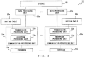
- FIG. 2 is a diagram that illustrates an example of a configuration of the communication device 10.
- the communication device 10 includes interfaces 11 (11a, 11b), communication processing units 20 (20a, 20b), routing tables 25 (25a, 25b), data processing units 30 (30a, 30b), and a storage 40.
- FIG. 2 is just an example, and there may be any number of interfaces 11, communication processing units 20, routing tables 25, and data processing units 30 being included in the communication device 10.
- one communication processing unit 20, one routing table 25, and one data processing unit 30 may be included in the communication device 10.
- FIG. 2 illustrates an example in which the number of interfaces 11, the number of communication processing units 20, the number of routing tables 25, and the number of data processing units 30 are the same and are equal to or more than two. Further, reference numerals are given to components in such a manner that the same letter is added after a number for each application with which the components are associated. For example, a packet that is to be processed by the application A1 is processed by use of the interface 11a, the communication processing unit 20a, the routing table 25a, and the data processing unit 30a. On the other hand, a packet that is to be processed by the application A2 is processed by use of the interface 11b, the communication processing unit 20b, the routing table 25b, and the data processing unit 30b.
- the interface 11 performs transmission and reception of a packet between the communication device 10 and a device to which the communication device 10 is connected.
- the communication processing unit 20 includes a transmission processing unit 22 and a reception processing unit 23.
- the transmission processing unit 22 generates a transmitting packet that includes data input from the data processing unit 30. Further, the transmission processing unit 22 performs processing of transmitting a packet through the interface 11 by referring to the routing table 25.
- the routing table 25 includes information associated with an application that processes the packet transmitted by the transmission processing unit 22.
- the routing table 25a includes routing information related to a network to which the interface 11a is connected
- the routing table 25b includes routing information related to a network to which the interface lib is connected.
- the data processing unit 30 terminates a packet and accordingly processes data included in the packet.
- the data processing unit 30, which is realized by use of a program of a certain application processes, using the application, the data obtained from the packet. Further, according to the setting of, for example, the program of the application, the data processing unit 30 provides the data to another program or invokes another program. For example, an API (application programming interface) used for invoking another program is also accordingly realized by the data processing unit 30.
- the data processing unit 30 stores, in the storage 40, the data along with the identification information on the application to which the data is to be provided. Further, the data processing unit 30 obtains, from the storage 40, the data in association with the identification information on the application that realizes the data processing unit 30, and outputs the data to the transmission processing unit 22 as data on which transmission processing is to be performed.
- FIG. 3 is a diagram that illustrates an example of a hardware configuration of the communication device 10.
- the communication device 10 includes a processor 101, a memory 102, a bus 103, and a network connecting device 104.
- a processor 101, one memory 102, and one network connecting device 104 are illustrated in the example of FIG. 3 , but there may be any number of processors 101, memories 102, and network connecting devices 104.
- the communication device 10 includes the same number of network connecting devices 104 as that of the private networks to which the communication device 10 can be connected.
- the processor 101 is any processing circuit that includes a CPU (central processing unit).
- the processor 101 uses the memory 102 as a working memory and executes a program, so as to perform various processes.
- the memory 102 includes a RAM (random access memory), and further includes a nonvolatile memory such as a ROM (read only memory) .
- the ROM stores therein a program.
- the memory 102 may accordingly include an external storage such as a hard disk.
- the bus 103 connects the processor 101, the memory 102, and the network connecting device 104 so that they can perform input and output of data between one another.
- the processor 101 operates as the data processing unit 30.
- the memory 102 operates as the storage 40.
- the memory 102 holds, for example, the routing table 25 and the data used for processing processor 101, and a program that is loaded into the processor 101.
- the network connecting device 104 operates as the interface 11.
- the communication processing unit 20 may be realized by the processor 101 and the network connecting device 104.
- the program may be provided stored in a computer-readable recording medium in a non-transitory manner so as to be installed in the communication device 10.
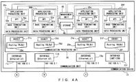
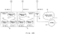
- FIGs. 4A and 4B are diagrams that illustrate an example of connections of the communication device 10 to networks. It is assumed that the communication device 10 of FIG. 4A is connected to a PAN (personal area network) 60, a FAN (field area network) 70, a gateway 80, and a carrier network 90. The communication device 10 is connected to the Internet 85 through the gateway 80. The gateway 80 operates as a default gateway when the communication device 10 communicates with the Internet 85. It is assumed that, in the carrier network 90 connected to the communication device 10, a private IP address is assigned to each user from a carrier side and a terminal of each of the users performs communication using the assigned private IP address.
- PAN personal area network
- FAN field area network
- FIGs. 4A and 4B illustrate an example in which the transmission processing unit 22 and the reception processing unit 23 are realized by a socket 21 that is used for a communication of each application.
- a communication unit 12 has interfaces 11 (11c to 11f) and the communication processing unit 20.
- each of the data processing units 30 has a base terminating unit 31, an API 32, and an application processing unit 33.
- the base terminating unit 31 terminates an input packet and outputs obtained data to the application processing unit 33.
- the application processing unit 33 processes the data accordingly and outputs, to the API 32, data to be processed by another application.
- the API 32 associates the input data with identification information on an application to which the data is to be provided, and outputs it to the storage 40.
- the identification information on an application is a value that is uniquely identified for each combination of a private network in which data is transmitted and received and an application that processes the data.
- the same type of program is used for processing data transmitted and received in the PAN 60 and data transmitted and received in the FAN 70.
- application identifying information that is assigned to an application that processes the data transmitted and received in the PAN 60 and application identifying information that is assigned to an application that processes the data transmitted and received in the FAN 70 are different from each other.
- a management unit 50 manages a relationship between a network to which the communication device 10 is connected and an application used for processing data. The management unit 50 accordingly generates management information ( FIG. 5 ) used by sockets 21c to 21f.
- a data processing unit 30c and the socket 21c perform processing related to an application used for processing data obtained from the PAN 60 (application a1).
- a base terminating unit 31c terminates a packet received from the PAN 60 through the interface 11c.
- An API 32c performs processing when the application a1 provides the data to another application.
- An application processing unit 33c realizes processing performed in the application a1.
- the socket 21c accordingly performs processing of transmitting a packet using a routing table 25c.
- a data processing unit 30d, a socket 21d, a routing table 25d, and the interface 11d are used for processing a packet transmitted to and received from the FAN 70, and for processing data obtained from the FAN 70. It is assumed that an application a2 is used for processing the data obtained from the FAN 70.
- a data processing unit 30e, a socket 21e, a routing table 25e, and the interface 11e are used for processing a packet transmitted and received through the gateway 80, and for processing data included in a received packet. It is assumed that an application b1 is used for processing the data included in the packet received through the gateway 80.
- a data processing unit 30f, a socket 21f, a routing table 25f, and the interface 11f are used for processing a packet transmitted and received through the carrier network 90, and for processing data obtained through the carrier network 90. It is assumed that an application b2 is used for processing data included in a packet received through the carrier network 90.
- FIGs. 4A and 4B illustrate a case in which the interfaces 11c to 11f are provided in the communication device 10, but the number of interfaces 11 in the communication device 10 may be discretionally changed.
- a process in which data is relayed between private networks through the communication device 10 will now be described, divided into a process in which data is received from a private network and a process in which processing of transmitting a packet from the communication device 10 is performed.
- the PAN 60 is a network of a location identifying service using BLE (Bluetooth low energy) and the FAN 70 is an ad-hoc network that controls a lighting-up of a streetlight using specified low power radio.
- the PAN 60 includes communication devices 61a to 61c and the FAN 70 includes communication devices 71a to 71c.
- a streetlight to be processed by the FAN 70 is lit up according to the location of a user that is identified by the location identifying service.
- the communication device 10 reports the location of a user A whose location is identified by the location identifying service to a user B who uses a smartphone to which a private IP address is assigned in the carrier network 90.
- 192.168.0.0 is also the address of a network that includes a connection between the communication device 10 and the gateway 80.
- 192.168.0.0 is an address of all the networks that respectively include the interfaces 11c to 11f included in the communication device 10, but the interfaces 11c to 11f belong to networks that are different from one another.
- 192.168.0.2 is assigned to both the communication device 61a and the communication device 71a as a private IP address. It is assumed that, likewise, 192.168.0.3 is assigned to the communication device 61b and the communication device 71b, and 192.168.0.4 is assigned to the communication device 61c and the communication device 71c.
- the communication device 61a operates as a gateway
- the communication device 71a operates as a gateway.
- Each of the communication device 61a and the communication device 71a is connected to the communication device 10 via Ethernet.
- the gateway 80 is also connected to the communication device 10 via Ethernet.
- the interface 11f is, for example, a 3G module that is connected through a UART (universal asynchronous receiver transmitter) or a USB (universal serial bus), and is used for a radio communication with a device included in the carrier network 90.
- the terminal device of the user A transmits a report signal to the communication device 61b.
- the communication device 61b When receiving the report signal, the communication device 61b generates a report packet for reporting that the user A exists around the communication device 61b, and transmits the report packet to the communication device 61a.
- any existing communication performed in a PAN may be applied.
- the communication device 61a transmits, to the communication device 10, a report packet for reporting that the user A is located in the communication area of the communication device 61b.
- a communication between the communication device 61a and the interface 11c of the communication device 10 is a communication performed in a private network.
- the interface 11c outputs the received packet to the socket 21c.
- the socket 21c identifies a data processing unit 30 that processes the input packet by use of management information generated in the management unit 50.
- FIG. 5 illustrates an example of management information.
- the management information associates an identification number of a physical interface, a port number, and application identifying information with one another.
- the physical interface is an interface 11
- the port number in the management information is a logical port number of a received packet. It is assumed that identification information IF1 is assigned to the interface 11c, IF2 to the interface 11d, IF3 to the interface 11e, and IF4 to the interface 11f.
- Each socket 21 identifies an application that processes data included in a received packet by use of a combination of the interface 11 that was used for the reception of a packet and the logical port number. For example, it is assumed that a destination port number of a packet which the communication device 10 has received from the communication device 61a through the interface 11c is 80. In this case, the identification information on a physical interface used for the reception of a packet is IF1, and the destination port number is 80, so the socket 21c determines that data included in the received packet is to be processed by the application a1. A packet to be processed by the application a1 is processed in the data processing unit 30c. Then, the socket 21c outputs the received packet to the base terminating unit 31c. The base terminating unit 31c terminates the input packet, and outputs information on a payload to the application processing unit 33c. The application processing unit 33c processes the input data.
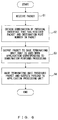
- FIG. 6 is a flowchart that illustrates an example of processing of receiving a packet in the communication device 10.
- the communication device 10 receives a packet through the interface 11 (Step S1).
- the socket 21 obtains a combination of a physical interface that has received a packet and a destination port number in the packet (Step S2).
- the socket 21 identifies an application corresponding to the combination, and outputs the packet to a base terminating unit 31 that is used when the identified application performs processing (Step S3) .
- the base terminating unit 31 processes the packet and outputs a payload to the application processing unit 33 (Step S4).
- the application processing unit 33c processes the data included in the report packet received from the communication device 61a, so as to determine that the user A is located around the communication device 61b.
- the application processing unit 33c has stored information that indicates a location of a streetlight controlled by the FAN 70, and identifies a location of a streetlight to be lit up, according to the location information on a user that has been reported by a device in the PAN 60.
- the application processing unit 33c also holds, for each streetlight, information on a communication device 71 that can be used to control the streetlight.
- the application processing unit 33c identifies a communication device 71 to which control information for lighting up a streetlight located in a predetermined range in the vicinity of the location of the user A is to be transmitted.
- the application processing unit 33c selects the communication device 71b as a communication destination. Then, the application processing unit 33c generates data to be transmitted to the communication device 71b.
- the application processing unit 33c further holds a table in which information on a user whose location information may be reported by the PAN 60 is associated with information on another device to which the location information is to be reported, and information used for reporting the location information.
- a table in which information on a user whose location information may be reported by the PAN 60 is associated with information on another device to which the location information is to be reported, and information used for reporting the location information.
- FIGs. 4A and 4B it is assumed that, when the location information on the user A is reported by the PAN 60, it is determined that the location information on the user A is to be reported to a smartphone 91 (not shown) that is used by the user B in the carrier network 90.
- the application processing unit 33c generates data to be transmitted to the smartphone 91.
- FIG. 7 illustrates examples of information elements included in data to be input and output.
- D1 of FIG. 7 is a payload included in a transmitting packet that is transmitted from the communication device 10, and is data that is to be relayed by the application processing unit 33 to another device.
- the application processing unit 33c generates pieces of data of packets to be transmitted to the communication device 71b and the smartphone 91, as payloads destined for these respective devices.
- the application processing unit 33c determines which application processes each of the pieces of data.
- the application processing unit 33c holds, in advance, information for identifying an application processing unit 33 to which data is to be relayed, according to the communication destination device. For example, each application processing unit 33 recognizes that processing is performed by the data processing unit 30c when data is to be relayed to a device in the PAN 60 and is performed by the data processing unit 30d when data is to be relayed to the FAN 70. Likewise, each application processing unit 33 also recognizes that processing is performed by the data processing unit 30e when data is to be relayed to a device on the Internet 85 and is performed by the data processing unit 30f when data is to be relayed to the carrier network 90.
- the application processing unit 33c determines to output a payload destined for the communication device 71b to an application processing unit 33d. Likewise, the application processing unit 33c determines to output a payload destined for the smartphone 91 to an application processing unit 33f.
- Each application processing unit 33 has stored identification information on an application that is executed in an application processing unit 33 that operates in the communication device 10, and associates a payload with identification information on an application of a relay destination and outputs it to the API 32.
- the application processing unit 33 further associates the combination of the payload and the identification information on an application of a relay destination with, for example, a destination address, and outputs it to the API 32.
- D2 of FIG. 7 illustrates an example of data which the application processing unit 33 outputs to the API 32.
- the application processing unit 33c determines to output a payload destined for the smartphone 91 to the application processing unit 33f.
- the identification information on an application executed in the application processing unit 33f is b2.
- information destined for the communication device 71b is processed.
- the identification information on an application executed in the application processing unit 33b is a2.
- the API 32c outputs the input information to the storage 40.
- Each of the data destined for the communication device 61b and the data destined for the smartphone 91 is also associated with information on a destination address of the data.
- the base terminating units 31c to 31f each confirm regularly whether data associated with identification information on an application by which the data is to be processed is stored in the storage 40.
- each of the base terminating units 31 obtains the data so as to generate a transmitting packet.
- each of data destined for the communication device 71b and data destined for the smartphone 91 is stored in the storage 40 along with an identifier of an application used for processing the data.
- the base terminating unit 31d generates a transmitting packet destined for the communication device 71b by use of the obtained data and the obtained information on a destination address.
- P11 of FIG. 7 illustrates an example of the transmitting packet generated by the base terminating unit 31d.
- the base terminating unit 31d removes application identifying information from information obtained from the storage 40, and adds a header used for transmission processing to data to be transmitted (payload).
- an IP header is added to the payload.
- the IP header includes version information, a header length, a type of service, a total data length, a packet identifier, a flag, a fragment offset, a time to live, a protocol, a checksum, a source IP address, a destination IP address, and an option.
- the source address of a packet destined for the communication device 71b is an address assigned to the interface 11d that is used for communicating with the FAN 70.
- information on an address of the packet destined for the communication device 71b is as follows.
- the base terminating unit 31d generates a transmitting packet destined for the smartphone 91 by use of the obtained data and the obtained information on a destination address. It is assumed that the address assigned to the smartphone 91 is 192.168.0.3. Then, information on an address of the packet destined for the smartphone 91 is as follows.
- the processing that is performed when the application processing unit 33 provides data to another application has been described above, but there is a possibility that data generated by the application processing unit 33 will not be output to another application.
- the application processing unit 33 determines to process the data to be relayed without providing it to another application. In this case, the application processing unit 33 outputs the data to be relayed to the base terminating unit 31.
- the base terminating unit 31 obtains information that corresponds to a payload.
- the base terminating unit 31 that has obtained the data from the application processing unit 33 generates a transmitting packet that has the same format as P11 of FIG. 7 .
- a base terminating unit 31 After it generates a transmitting packet, a base terminating unit 31 outputs the generated transmitting packet to a socket 21 that performs processing related to the same application as the application for which the base terminating unit 31 is used. For example, the base terminating unit 31d outputs, to the socket 21d, the transmitting packet generated for the communication device 71b.
- the socket 21d refers to the routing table 25d.
- FIG. 8 illustrates examples of routing tables 25.
- the routing tables 25c to 25f of FIG. 8 are generated.
- the routing table 25c is a table used for routing to the PAN 60
- the routing table 25d is a table used for routing to the FAN 70.
- the routing table 25e is used for performing processing of transmitting a packet transmitted to the Internet 85 through the gateway 80
- the routing table 25f is used for performing processing of transmission to the carrier network 90.
- Each of the routing tables includes information that identifies a network address of a transfer destination network and information on the transfer destination. As illustrated in FIGs.
- the communication device 10 when four networks having the same network address are connected to the communication device 10, the communication device 10 records pieces of transfer information in which the same network address is used, as the routing tables 25c to 25f indicate.
- the transfer information on each network is associated with identification information on an application that processes a packet transmitted and received in the network.
- the socket 21 can distinguish a plurality of networks that use the same private address by the application identifying information.
- a destination private network that is identified by use of the application identifying information is indicated parenthetically in DESTINATION IP ADDRESS.
- a reference numeral assigned to a device that is identified by use of the application identifying information is indicated parenthetically.
- the routing table 25d indicates information on a route to a network whose network address is 192.168.0.0 by use of a destination IP address and a netmask.
- the routing table 25d indicates a transfer route to the FAN 70.
- the socket 21d may have stored the information that an output destination of a transmitting packet from the socket 21d is the interface 11d.
- the socket 21d refers to the routing table 25d so as to output the transmitting packet to the interface 11d.
- information on a transfer destination and an address of the transmitting packet is as follows.
- the communication device 71a that has received a packet from the communication device 10 transfers the packet to the communication device 71b.
- the packet destined for the communication device 71b is a control packet that makes a request to light up a streetlight controlled by the communication device 71b.
- the communication device 71b processes the received packet so as to light up the streetlight controlled by the communication device 71b. Accordingly, a streetlight around the location of the user A is lit up.
- the socket 21f refers to the routing table 25f so as to output the transmitting packet to the interface 11t.
- information on a transfer destination and an address of the transmitting packet is as follows.
- the gateway in the carrier network 90 that has received the packet from the communication device 10 transfers the packet to the smartphone 91.
- the packet destined for the smartphone 91 is information that reports information on the location of the user A.
- the smartphone 91 performs processing of, for example, accordingly displaying, on a screen, information in the received packet, so as to report the location of the user A to the user B using the smartphone 91.
- the base terminating unit 31 may output the data to the API 32.
- the transmitted data is output to the base terminating unit 31 in combination with application identifying information even when the data is destined for any of the networks.
- FIG. 9 illustrates an example of processing that is performed when transmitted data is distributed by the base terminating unit 31.
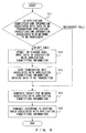
- FIG. 9 is a flowchart that illustrates an example of processing of transmitting a packet in the communication device 10.
- the base terminating unit 31 determines whether identifying information associated with data to be transmitted is application identifying information associated with a network to be processed (Step S11). When the identification information associated with the data is not the application identifying information associated with the network on which the base terminating unit 31 itself performs processing, the base terminating unit 31 outputs the data and the identification information associated with the data to the API 32 (No in Step S11).
- the API 32 stores, in an area (storage 40) that stores therein pieces of data to be transferred to a plurality of networks, the input data in association with application identifying information (Step S12) .
- Abase terminating unit 31 associated with the application identifying information obtains the data to be transmitted from the storage 40 (Step S13).
- the base terminating unit 31 generates a packet for a network associated with the application identifying information and outputs it to the socket 21 (Step S14).
- the socket 21 performs transmission processing according to the routing table 25 associated with the application identifying information (Step S15).
- Step S14 when the identification information associated with the data is the application identifying information associated with the network on which the base terminating unit 31 itself performs processing, the processes of and after Step S14 are performed (Yes in Step S11).
- the communication device 10 determines a route from a combination of information on an application that processes a packet in each of the networks and routing information.
- a data relay between devices of the private networks can be easily performed, even though it has been difficult to perform such a data relay even by NAPT.
- a content of the processing performed in the application processing unit 33 may be discretionally changed according to the program that will be loaded into the communication device 10.
- the application processing unit 33c performs processing by use of received data so as to generate data that is different from data included in a payload of a received packet, but it is acceptable if data processing is not performed in the application processing unit 33.
- the application processing unit 33 deals with the received data as transmitted data destined for an application used for processing performed in another network, so as to provide the data to another application. As a result, processing of transferring data is performed between private networks.
- a vendor of the communication device 10 can perform designing so that an operator who offers a service of a network that uses the communication device 10 can freely design processing performed in the application processing unit 33.
- the operator loads, into the communication device 10, a program according to the service he/she intends to offer to a user, so as to realize, by means of the processor 101 in the communication device 10, an application processing unit 33 that offers a desired service.
- transmission and reception of data can be easily performed between different networks.
- one application is registered for each physical interface, but a plurality of applications may be associated with each physical interface.
- the networks illustrated in FIGs. 4A and 4B are just examples, and some of the networks connected to the communication device 10 may have different network addresses. Further, information elements included in a table such as the management information of FIG. 5 or the routing tables 25 of FIG. 8 may be changed depending on implementation.
- routing tables 25 each corresponding to a different application identifier are used has been described with reference to FIGS. 2 , 4A and 4B , but the number of routing tables 25 held by the communication device 10 may be one.
- the transmission processing unit 22 searches in the routing table 25 for information associated with identification information on an application that processes a packet to be transmitted.
- the communication device 10 may transmit data generated in the communication device 10 to a device included in a private network.
Landscapes
- Engineering & Computer Science (AREA)
- Computer Networks & Wireless Communication (AREA)
- Signal Processing (AREA)
- Computer Security & Cryptography (AREA)
- Computer Hardware Design (AREA)
- Computing Systems (AREA)
- General Engineering & Computer Science (AREA)
- Data Exchanges In Wide-Area Networks (AREA)
Abstract
Description
- The embodiments discussed herein are related to a communication device and communication performed by the communication device.
- With the miniaturization of communication equipment and the development of wireless technologies, a network including a machine or sensor that is equipped with communication equipment has been increasingly used for gathering information. Further, private networks are often used in such a network. A device in a private network transmits data to a gateway, and the gateway accordingly reports data to, for example, a server. When the gateway communicates with a server that is not situated in a private network, Network Address Port Translation (NAPT) is accordingly performed by, for example, a router that relays a communication between the gateway and the server. When data obtained in a certain private network is used in another private network, communication may occur between devices included in different private networks. Also, when the communication between devices in different private networks is performed, Network Address Port Translation is accordingly performed by a router that connects the private networks.
- As a related technology, a terminal device that includes a routing table that stores therein a gateway for a constant connection and a gateway device for a temporary connection has been devised. A communication between the terminal device and a communication destination is performed through the gateway for a constant connection, but a route using the gateway device for a temporary connection is used when a route through the gateway for a constant connection is not allowed to be used. Further, a network communication system in which a transmitter information processing unit transmits data along with routing information that specifies the order in which the data passes, from the transmitter side to a destination, through routers included in a network has also been devised. Furthermore, a distribution system in which each node associates information about a physical position of a node with an identifier of an application that operates on the node and stores them therein has been proposed. This distribution system permits, when an application that operates on a first node communicates with an application that operates on a second node, extracting of pieces of information on the positions of the nodes on the basis of the identification information on an application, so as to determine communication means from the pieces of information on the positions.
- For example, documents such as
Japanese Laid-open Patent Publication No. 2002-158665 Japanese Laid-open Patent Publication No. 2005-45535 International Publication No. 2011/045919 - When data obtained in a certain private network is used in another private network, data passing between devices included in different private networks will be performed. In this case, communication using Network Address Port Translation is often performed, but in some cases, it may be difficult to perform communication even if Network Address Port Translation is used. For example, when a private IP address assigned to a source device is consistent with a private IP address assigned to a destination device, a transmitted packet, without becoming subject to Network Address Port Translation, reverts back to the source device. On the other hand, it is also difficult to perform communication between devices included in different private networks even if a relay device on a route is set up individually without using Network Address Port Translation.
- In one aspect, an object of the present invention is to easily perform transmission and reception of data between devices included in different private networks.
- According to an aspect of the embodiments, a communication device includes a receiver, a data processing unit, a routing table, and a transmitter. The receiver receives a certain packet from one of a plurality of networks. The data processing unit processes the certain packet and identifies a use application that is an application used for processing another packet transmitted and received in a network that is a relay destination of data obtained by use of the certain packet. The routing table associates, for each of the plurality of networks, a transfer route that is used in the network with identification information on an application that processes the another packet transmitted and received in the network. The transmitter generates a transmitting packet including the data and transmits the transmitting packet using a transfer route that is associated, in the routing table, with identification information that identifies the use application.
-
-
FIG. 1 is a diagram that illustrates an example of a communication method according to embodiments; -
FIG. 2 is a diagram that illustrates an example of a configuration of a communication device; -
FIG. 3 is a diagram that illustrates an example of a hardware configuration of the communication device; -
FIGs. 4A and4B are a diagram that illustrates an example of connections of the communication device to networks; -
FIG. 5 illustrates an example of management information; -
FIG. 6 is a flowchart that illustrates an example of processing of receiving a packet in the communication device; -
FIG. 7 illustrates examples of information elements included in data to be input and output; -
FIG. 8 illustrates examples of routing tables; and -
FIG. 9 is a flowchart that illustrates an example of processing of transmitting a packet in the communication device. -
FIG. 1 is a diagram that illustrates an example of a communication method according to embodiments. It is assumed that networks N1 to N3 that are individual private networks are formed, as illustrated in Case C1 ofFIG. 1 . Assignment of a private IP address is performed in each of the networks without considering assignment of an address in other networks, so the same private IP address may be assigned to a plurality of devices. For example, it is assumed that the same private IP address is assigned to acommunication device 5a in the network N1, acommunication device 5b in the network N2, and acommunication device 5c in the network N3. The address assigned to thecommunication devices 5a to 5c is hereinafter referred to as PA. Further, it is assumed that all the network addresses of the networks N1 to N3 have the same value (IPnet). - Next, it is assumed that, as illustrated in Case C2 of
FIG. 1 , the networks N1 to N3 are connected to acommunication device 10 in order to report data obtained in thecommunication device 5a to thecommunication device 5b and thecommunication device 5c. In the example of Case C2, thecommunication device 10 has interfaces IF1 to IF3 and is connected to the network N1, the network N2, and the network N3 through the interface IF1, the interface IF2, and the interface IF3, respectively. Further, it is assumed that a packet transmitted and received in the network N1 is processed by an application A1, a packet transmitted and received in the network N2 is processed by an application A2, and a packet transmitted and received in the network N3 is processed by an application A3. The applications A1 to A3 are operable in thecommunication device 10, each of which includes information on processing which it performs on a packet to be processed. - It is assumed that the
communication device 10 has received a packet P1 from thecommunication device 5a through the interface IF1. A source address of the packet P1 is the private IP address (PA) of thecommunication device 5a. Thecommunication device 10 processes the packet P1 using the application A1 that processes a packet transmitted and received in the network N1. In this case, the processing performed on the packet P1 may be a termination of the packet, or may be the termination of the packet and processing performed on data stored in a payload of the packet. - The
communication device 10 identifies an application used in a network to which data obtained by performing the processing on the packet P1 is to be relayed. When the data obtained by performing the processing on the packet P1 is relayed to thecommunication devices communication device 10 generates a packet to be transmitted (transmitting packet) including data to be relayed in a form corresponding to each relay destination network. In the example ofFIG. 1 , a packet P2 is generated to be destined for the network N2, and a packet P3 is generated to be destined for the network N3. Further, as a private IP address, PA is assigned to both of thecommunication device 5b that is a destination of the packet P2 and thecommunication device 5c that is a destination of the packet P3, so PA is a destination address for both of the packets P2 and P3. - As represented in a table T1, the
communication device 10 stores therein a communication route and an interface in association with identification information on an application, wherein the communication route and the interface are used for performing processing of transferring to each network to which thecommunication device 10 is connected and the application is used for processing a packet transmitted and received in each of the networks. In this case, all the network addresses of the networks N1 to N3 have the same value, so it is not possible to know which entry includes information that can be used for the transfer processing if only routing information is provided. - The packet P2 is a packet destined for the network N2 that is to be processed by the application A2, so the
communication device 10 transmits the packet P2 from the interface IF2 using the routing information associated with the identification information on the application A2. On the other hand, the packet P3 is a packet destined for the network N3 that is to be processed by the application A3, so thecommunication device 10 transmits the packet P3 from the interface IF3 using the routing information associated with the identification information on the application A3. Thus, although the destination addresses of both of the packets P2 and P3 are PA and the network addresses of both of the networks N2 and N3 are IPnet, thecommunication device 10 can transmit the packet P2 to thecommunication device 5b and the packet P3 to thecommunication device 5c. - As described above, when a plurality of private networks having the same private address are connected to the
communication device 10, thecommunication device 10 determines a route from a combination of information on an application that processes a packet and routing information. Accordingly, if the private networks are connected to one another through thecommunication device 10, a data relay between devices included in the private networks can be easily performed, though it has been difficult to perform such a data relay even using NAPT. - Further, the
communication device 10 also determines whether to process a packet received from a communication device 5 in a private network and to relay data to another network. Thus, a communication device 5 in each private network does not have to determine whether to report data to a device in another private network, which results in reducing a processing load of a device in the communication device 5. -
FIG. 2 is a diagram that illustrates an example of a configuration of thecommunication device 10. Thecommunication device 10 includes interfaces 11 (11a, 11b), communication processing units 20 (20a, 20b), routing tables 25 (25a, 25b), data processing units 30 (30a, 30b), and astorage 40.FIG. 2 is just an example, and there may be any number ofinterfaces 11,communication processing units 20, routing tables 25, anddata processing units 30 being included in thecommunication device 10. For example, as described inFIG. 1 , onecommunication processing unit 20, one routing table 25, and onedata processing unit 30 may be included in thecommunication device 10. - For visual clarity,
FIG. 2 onwards illustrate an example in which the number ofinterfaces 11, the number ofcommunication processing units 20, the number of routing tables 25, and the number ofdata processing units 30 are the same and are equal to or more than two. Further, reference numerals are given to components in such a manner that the same letter is added after a number for each application with which the components are associated. For example, a packet that is to be processed by the application A1 is processed by use of theinterface 11a, thecommunication processing unit 20a, the routing table 25a, and thedata processing unit 30a. On the other hand, a packet that is to be processed by the application A2 is processed by use of theinterface 11b, thecommunication processing unit 20b, the routing table 25b, and thedata processing unit 30b. - The
interface 11 performs transmission and reception of a packet between thecommunication device 10 and a device to which thecommunication device 10 is connected. Thecommunication processing unit 20 includes a transmission processing unit 22 and a reception processing unit 23. The transmission processing unit 22 generates a transmitting packet that includes data input from thedata processing unit 30. Further, the transmission processing unit 22 performs processing of transmitting a packet through theinterface 11 by referring to the routing table 25. As illustrated inFIG. 2 , when thecommunication processing unit 20 and other components are provided for each application, the routing table 25 includes information associated with an application that processes the packet transmitted by the transmission processing unit 22. For example, the routing table 25a includes routing information related to a network to which theinterface 11a is connected, and the routing table 25b includes routing information related to a network to which the interface lib is connected. - The
data processing unit 30 terminates a packet and accordingly processes data included in the packet. For example, thedata processing unit 30, which is realized by use of a program of a certain application processes, using the application, the data obtained from the packet. Further, according to the setting of, for example, the program of the application, thedata processing unit 30 provides the data to another program or invokes another program. For example, an API (application programming interface) used for invoking another program is also accordingly realized by thedata processing unit 30. When it provides the data to another program, thedata processing unit 30 stores, in thestorage 40, the data along with the identification information on the application to which the data is to be provided. Further, thedata processing unit 30 obtains, from thestorage 40, the data in association with the identification information on the application that realizes thedata processing unit 30, and outputs the data to the transmission processing unit 22 as data on which transmission processing is to be performed. -
FIG. 3 is a diagram that illustrates an example of a hardware configuration of thecommunication device 10. Thecommunication device 10 includes aprocessor 101, amemory 102, abus 103, and anetwork connecting device 104. For purposes of clarity, oneprocessor 101, onememory 102, and onenetwork connecting device 104 are illustrated in the example ofFIG. 3 , but there may be any number ofprocessors 101,memories 102, and network connectingdevices 104. For example, when a differentnetwork connecting device 104 is used for each private network to which thecommunication device 10 is connected, thecommunication device 10 includes the same number ofnetwork connecting devices 104 as that of the private networks to which thecommunication device 10 can be connected. - The
processor 101 is any processing circuit that includes a CPU (central processing unit). Theprocessor 101 uses thememory 102 as a working memory and executes a program, so as to perform various processes. Thememory 102 includes a RAM (random access memory), and further includes a nonvolatile memory such as a ROM (read only memory) . The ROM stores therein a program. Thememory 102 may accordingly include an external storage such as a hard disk. Thebus 103 connects theprocessor 101, thememory 102, and thenetwork connecting device 104 so that they can perform input and output of data between one another. In thecommunication device 10, theprocessor 101 operates as thedata processing unit 30. Thememory 102 operates as thestorage 40. Further, thememory 102 holds, for example, the routing table 25 and the data used for processingprocessor 101, and a program that is loaded into theprocessor 101. Thenetwork connecting device 104 operates as theinterface 11. Thecommunication processing unit 20 may be realized by theprocessor 101 and thenetwork connecting device 104. The program may be provided stored in a computer-readable recording medium in a non-transitory manner so as to be installed in thecommunication device 10. -
FIGs. 4A and4B are diagrams that illustrate an example of connections of thecommunication device 10 to networks. It is assumed that thecommunication device 10 ofFIG. 4A is connected to a PAN (personal area network) 60, a FAN (field area network) 70, agateway 80, and acarrier network 90. Thecommunication device 10 is connected to theInternet 85 through thegateway 80. Thegateway 80 operates as a default gateway when thecommunication device 10 communicates with theInternet 85. It is assumed that, in thecarrier network 90 connected to thecommunication device 10, a private IP address is assigned to each user from a carrier side and a terminal of each of the users performs communication using the assigned private IP address. -
FIGs. 4A and4B illustrate an example in which the transmission processing unit 22 and the reception processing unit 23 are realized by a socket 21 that is used for a communication of each application. Acommunication unit 12 has interfaces 11 (11c to 11f) and thecommunication processing unit 20. In the example ofFIGs. 4A andB , each of thedata processing units 30 has a base terminating unit 31, an API 32, and an application processing unit 33. The base terminating unit 31 terminates an input packet and outputs obtained data to the application processing unit 33. The application processing unit 33 processes the data accordingly and outputs, to the API 32, data to be processed by another application. The API 32 associates the input data with identification information on an application to which the data is to be provided, and outputs it to thestorage 40. - In this case, the identification information on an application is a value that is uniquely identified for each combination of a private network in which data is transmitted and received and an application that processes the data. For example, it is assumed that the same type of program is used for processing data transmitted and received in the
PAN 60 and data transmitted and received in theFAN 70. Even in this case, application identifying information that is assigned to an application that processes the data transmitted and received in thePAN 60 and application identifying information that is assigned to an application that processes the data transmitted and received in theFAN 70 are different from each other. Amanagement unit 50 manages a relationship between a network to which thecommunication device 10 is connected and an application used for processing data. Themanagement unit 50 accordingly generates management information (FIG. 5 ) used bysockets 21c to 21f. - In the example of
FIG. 4A , adata processing unit 30c and thesocket 21c perform processing related to an application used for processing data obtained from the PAN 60 (application a1). Abase terminating unit 31c terminates a packet received from thePAN 60 through theinterface 11c. AnAPI 32c performs processing when the application a1 provides the data to another application. Anapplication processing unit 33c realizes processing performed in the application a1. Thesocket 21c accordingly performs processing of transmitting a packet using a routing table 25c. - Likewise, a
data processing unit 30d, asocket 21d, a routing table 25d, and theinterface 11d are used for processing a packet transmitted to and received from theFAN 70, and for processing data obtained from theFAN 70. It is assumed that an application a2 is used for processing the data obtained from theFAN 70. Adata processing unit 30e, asocket 21e, a routing table 25e, and theinterface 11e are used for processing a packet transmitted and received through thegateway 80, and for processing data included in a received packet. It is assumed that an application b1 is used for processing the data included in the packet received through thegateway 80. Adata processing unit 30f, asocket 21f, a routing table 25f, and theinterface 11f are used for processing a packet transmitted and received through thecarrier network 90, and for processing data obtained through thecarrier network 90. It is assumed that an application b2 is used for processing data included in a packet received through thecarrier network 90. - In order to facilitate the explanation of the operation of the
communication device 10 when it is connected to four networks,FIGs. 4A and4B illustrate a case in which theinterfaces 11c to 11f are provided in thecommunication device 10, but the number ofinterfaces 11 in thecommunication device 10 may be discretionally changed. - A process in which data is relayed between private networks through the
communication device 10 will now be described, divided into a process in which data is received from a private network and a process in which processing of transmitting a packet from thecommunication device 10 is performed. In the following example, it is assumed that thePAN 60 is a network of a location identifying service using BLE (Bluetooth low energy) and theFAN 70 is an ad-hoc network that controls a lighting-up of a streetlight using specified low power radio. ThePAN 60 includescommunication devices 61a to 61c and theFAN 70 includescommunication devices 71a to 71c. It is assumed that a streetlight to be processed by theFAN 70 is lit up according to the location of a user that is identified by the location identifying service. It is also assumed that thecommunication device 10 reports the location of a user A whose location is identified by the location identifying service to a user B who uses a smartphone to which a private IP address is assigned in thecarrier network 90. - In the example of
FIGs. 4A and4B , it is assumed that all of the network addresses of thePAN 60, theFAN 70, and thecarrier network 90 are set to 192.168.0.0. Further, it is assumed that 192.168.0.0 is also the address of a network that includes a connection between thecommunication device 10 and thegateway 80. In other words, in the example ofFIGs. 4A and4B , 192.168.0.0 is an address of all the networks that respectively include theinterfaces 11c to 11f included in thecommunication device 10, but theinterfaces 11c to 11f belong to networks that are different from one another. Furthermore, it is assumed that 192.168.0.2 is assigned to both thecommunication device 61a and thecommunication device 71a as a private IP address. It is assumed that, likewise, 192.168.0.3 is assigned to thecommunication device 61b and thecommunication device 71b, and 192.168.0.4 is assigned to thecommunication device 61c and thecommunication device 71c. - It is assumed that, in the
PAN 60, thecommunication device 61a operates as a gateway, and in theFAN 70, thecommunication device 71a operates as a gateway. Each of thecommunication device 61a and thecommunication device 71a is connected to thecommunication device 10 via Ethernet. Further, in the example ofFIGs. 4A and4B , thegateway 80 is also connected to thecommunication device 10 via Ethernet. Theinterface 11f is, for example, a 3G module that is connected through a UART (universal asynchronous receiver transmitter) or a USB (universal serial bus), and is used for a radio communication with a device included in thecarrier network 90. - It is assumed that the user A moves while carrying a terminal device and then the terminal device of the user A enters a communication area of the
communication device 61b. Then, the terminal device of the user A transmits a report signal to thecommunication device 61b. When receiving the report signal, thecommunication device 61b generates a report packet for reporting that the user A exists around thecommunication device 61b, and transmits the report packet to thecommunication device 61a. With respect to a format of a report packet and a communication procedure in thePAN 60, any existing communication performed in a PAN may be applied. Thecommunication device 61a transmits, to thecommunication device 10, a report packet for reporting that the user A is located in the communication area of thecommunication device 61b. In this case, a communication between thecommunication device 61a and theinterface 11c of thecommunication device 10 is a communication performed in a private network. - The
interface 11c outputs the received packet to thesocket 21c. Thesocket 21c identifies adata processing unit 30 that processes the input packet by use of management information generated in themanagement unit 50. -
FIG. 5 illustrates an example of management information. The management information associates an identification number of a physical interface, a port number, and application identifying information with one another. In this case, the physical interface is aninterface 11, and the port number in the management information is a logical port number of a received packet. It is assumed that identification information IF1 is assigned to theinterface 11c, IF2 to theinterface 11d, IF3 to theinterface 11e, and IF4 to theinterface 11f. - Each socket 21 identifies an application that processes data included in a received packet by use of a combination of the
interface 11 that was used for the reception of a packet and the logical port number. For example, it is assumed that a destination port number of a packet which thecommunication device 10 has received from thecommunication device 61a through theinterface 11c is 80. In this case, the identification information on a physical interface used for the reception of a packet is IF1, and the destination port number is 80, so thesocket 21c determines that data included in the received packet is to be processed by the application a1. A packet to be processed by the application a1 is processed in thedata processing unit 30c. Then, thesocket 21c outputs the received packet to thebase terminating unit 31c. Thebase terminating unit 31c terminates the input packet, and outputs information on a payload to theapplication processing unit 33c. Theapplication processing unit 33c processes the input data. -
FIG. 6 is a flowchart that illustrates an example of processing of receiving a packet in thecommunication device 10. Thecommunication device 10 receives a packet through the interface 11 (Step S1). The socket 21 obtains a combination of a physical interface that has received a packet and a destination port number in the packet (Step S2). The socket 21 identifies an application corresponding to the combination, and outputs the packet to a base terminating unit 31 that is used when the identified application performs processing (Step S3) . The base terminating unit 31 processes the packet and outputs a payload to the application processing unit 33 (Step S4). - In the example of the processing of receiving a packet that has been described with reference to
FIGs. 4A and4B , theapplication processing unit 33c processes the data included in the report packet received from thecommunication device 61a, so as to determine that the user A is located around thecommunication device 61b. Theapplication processing unit 33c has stored information that indicates a location of a streetlight controlled by theFAN 70, and identifies a location of a streetlight to be lit up, according to the location information on a user that has been reported by a device in thePAN 60. Theapplication processing unit 33c also holds, for each streetlight, information on a communication device 71 that can be used to control the streetlight. Using these pieces of information, theapplication processing unit 33c identifies a communication device 71 to which control information for lighting up a streetlight located in a predetermined range in the vicinity of the location of the user A is to be transmitted. In the example ofFIGs. 4A and4B , it is assumed that, in order to light up the streetlight in the vicinity of the user A, theapplication processing unit 33c selects thecommunication device 71b as a communication destination. Then, theapplication processing unit 33c generates data to be transmitted to thecommunication device 71b. - It is assumed that the
application processing unit 33c further holds a table in which information on a user whose location information may be reported by thePAN 60 is associated with information on another device to which the location information is to be reported, and information used for reporting the location information. In the example ofFIGs. 4A and4B , it is assumed that, when the location information on the user A is reported by thePAN 60, it is determined that the location information on the user A is to be reported to a smartphone 91 (not shown) that is used by the user B in thecarrier network 90. Theapplication processing unit 33c generates data to be transmitted to the smartphone 91. -
FIG. 7 illustrates examples of information elements included in data to be input and output. D1 ofFIG. 7 is a payload included in a transmitting packet that is transmitted from thecommunication device 10, and is data that is to be relayed by the application processing unit 33 to another device. In the example described with reference toFIGs. 4A and4B , theapplication processing unit 33c generates pieces of data of packets to be transmitted to thecommunication device 71b and the smartphone 91, as payloads destined for these respective devices. - When pieces of data to be relayed are obtained, the
application processing unit 33c determines which application processes each of the pieces of data. Theapplication processing unit 33c holds, in advance, information for identifying an application processing unit 33 to which data is to be relayed, according to the communication destination device. For example, each application processing unit 33 recognizes that processing is performed by thedata processing unit 30c when data is to be relayed to a device in thePAN 60 and is performed by thedata processing unit 30d when data is to be relayed to theFAN 70. Likewise, each application processing unit 33 also recognizes that processing is performed by thedata processing unit 30e when data is to be relayed to a device on theInternet 85 and is performed by thedata processing unit 30f when data is to be relayed to thecarrier network 90. Using these pieces of information, theapplication processing unit 33c determines to output a payload destined for thecommunication device 71b to anapplication processing unit 33d. Likewise, theapplication processing unit 33c determines to output a payload destined for the smartphone 91 to anapplication processing unit 33f. - Each application processing unit 33 has stored identification information on an application that is executed in an application processing unit 33 that operates in the
communication device 10, and associates a payload with identification information on an application of a relay destination and outputs it to the API 32. The application processing unit 33 further associates the combination of the payload and the identification information on an application of a relay destination with, for example, a destination address, and outputs it to the API 32. - D2 of
FIG. 7 illustrates an example of data which the application processing unit 33 outputs to the API 32. For example, theapplication processing unit 33c determines to output a payload destined for the smartphone 91 to theapplication processing unit 33f. Here, it is assumed that the identification information on an application executed in theapplication processing unit 33f is b2. Then, theapplication processing unit 33c associates a payload of a packet destined for the smartphone 91 with the information "application identifying information=b2", and outputs it to theAPI 32c. Likewise, information destined for thecommunication device 71b is processed. For example, it is assumed that the identification information on an application executed in the application processing unit 33b is a2. In this case, theapplication processing unit 33c outputs a combination of a payload of a packet destined for thecommunication device 71b with the information "application identifying information=a2" to theAPI 32c. When the combination of a payload and application identifying information is input, theAPI 32c outputs the input information to thestorage 40. Each of the data destined for thecommunication device 61b and the data destined for the smartphone 91 is also associated with information on a destination address of the data. - The
base terminating units 31c to 31f each confirm regularly whether data associated with identification information on an application by which the data is to be processed is stored in thestorage 40. When the data associated with the identification information on an application by which the data is to be processed is stored in thestorage 40, each of the base terminating units 31 obtains the data so as to generate a transmitting packet. For example, as a result of the processing performed by theAPI 32c, each of data destined for thecommunication device 71b and data destined for the smartphone 91 is stored in thestorage 40 along with an identifier of an application used for processing the data. Then, thebase terminating unit 31d obtains data associated with application identifying information=a2, and information on, for example, a destination address. Thebase terminating unit 31d generates a transmitting packet destined for thecommunication device 71b by use of the obtained data and the obtained information on a destination address. - P11 of
FIG. 7 illustrates an example of the transmitting packet generated by thebase terminating unit 31d. Thebase terminating unit 31d removes application identifying information from information obtained from thestorage 40, and adds a header used for transmission processing to data to be transmitted (payload). In the example of P11, an IP header is added to the payload. The IP header includes version information, a header length, a type of service, a total data length, a packet identifier, a flag, a fragment offset, a time to live, a protocol, a checksum, a source IP address, a destination IP address, and an option. The source address of a packet destined for thecommunication device 71b is an address assigned to theinterface 11d that is used for communicating with theFAN 70. Thus, information on an address of the packet destined for thecommunication device 71b is as follows. - Source IP address: 192.168.0.1 (
interface 11d) - Destination IP address: 192.168.0.3 (
communication device 71b) - Likewise, the
base terminating unit 31f accesses thestorage 40 so as to obtain data associated with application identifying information=b2, and information on, for example, a destination address. Thebase terminating unit 31d generates a transmitting packet destined for the smartphone 91 by use of the obtained data and the obtained information on a destination address. It is assumed that the address assigned to the smartphone 91 is 192.168.0.3. Then, information on an address of the packet destined for the smartphone 91 is as follows. - Source IP address: 192.168.0.1 (
interface 11f) - Destination IP address: 192.168.0.3 (smartphone 91)
- The processing that is performed when the application processing unit 33 provides data to another application has been described above, but there is a possibility that data generated by the application processing unit 33 will not be output to another application. For example, when data to be relayed is relayed to the same destination network as that of a transmitting packet, the application processing unit 33 determines to process the data to be relayed without providing it to another application. In this case, the application processing unit 33 outputs the data to be relayed to the base terminating unit 31. Thus, as illustrated in D1 of
FIG. 7 , the base terminating unit 31 obtains information that corresponds to a payload. The base terminating unit 31 that has obtained the data from the application processing unit 33 generates a transmitting packet that has the same format as P11 ofFIG. 7 . - After it generates a transmitting packet, a base terminating unit 31 outputs the generated transmitting packet to a socket 21 that performs processing related to the same application as the application for which the base terminating unit 31 is used. For example, the
base terminating unit 31d outputs, to thesocket 21d, the transmitting packet generated for thecommunication device 71b. Thesocket 21d refers to the routing table 25d. -
FIG. 8 illustrates examples of routing tables 25. In a system in which different routing tables 25 are generated for each application as illustrated inFIGs. 4A and4B , the routing tables 25c to 25f ofFIG. 8 are generated. The routing table 25c is a table used for routing to thePAN 60, and the routing table 25d is a table used for routing to theFAN 70. Likewise, the routing table 25e is used for performing processing of transmitting a packet transmitted to theInternet 85 through thegateway 80, and the routing table 25f is used for performing processing of transmission to thecarrier network 90. Each of the routing tables includes information that identifies a network address of a transfer destination network and information on the transfer destination. As illustrated inFIGs. 4A and4B , when four networks having the same network address are connected to thecommunication device 10, thecommunication device 10 records pieces of transfer information in which the same network address is used, as the routing tables 25c to 25f indicate. However, as illustrated inFIG. 8 , the transfer information on each network is associated with identification information on an application that processes a packet transmitted and received in the network. Thus, the socket 21 can distinguish a plurality of networks that use the same private address by the application identifying information. - In order to facilitate understanding, in
FIG. 8 , a destination private network that is identified by use of the application identifying information is indicated parenthetically in DESTINATION IP ADDRESS. Also, in INTERFACE and GATEWAY, a reference numeral assigned to a device that is identified by use of the application identifying information is indicated parenthetically. A specific example of how to understand each of the routing tables 25 by use of the application identifier is described below. - For example, the routing table 25d includes routing information associated with an application (application identifying information=a2) that is used for processing a packet transmitted and received in the
FAN 70. The routing table 25d indicates information on a route to a network whose network address is 192.168.0.0 by use of a destination IP address and a netmask. The network in which a packet is processed by the application identified by application identifying information=a2 and whose network address is 192.168.0.0 is theFAN 70. Thus, the routing table 25d indicates a transfer route to theFAN 70. In the routing table 25d, when the transmission to the network whose network address=192.168.0.0 is performed, the address of an interface is 192.168.0.1 and the address of a gateway is 192.168.0.2. In this case, the information included in the routing table 25d is associated with application identifying information=a2, so this is the information when communication with theFAN 70 is performed. Therefore, the interface included in the routing table 25d (192.168.0.1) refers to theinterface 11d, and the gateway included in the routing table 25d (192.168.0.2) refers to thecommunication device 71a. - Likewise, the routing table 25f is associated with an application that processes the information on the carrier network 90 (application identifying information=b2), so the destination IP address 192.168.0.0 refers to the
carrier network 90. Further, in the routing table 25f, the interface (192.168.0.1) refers to theinterface 11f, and the gateway (192.168.0.2) refers to a gateway device (not shown) in thecarrier network 90. - The routing table 25e is associated with an application that processes information destined for the Internet 85 (application identifying information=b1), so the destination IP address 192.168.0.0 refers to a network including the
gateway 80. Further, in the routing table 25e, the interface (192.168.0.1) refers to theinterface 11e, and the gateway (192.168.0.2) refers to thegateway 80. - The routing table 25c is associated with an application that processes information destined for the PAN 60 (application identifying information=a1), so the destination IP address 192.168.0.0 refers to the
PAN 60. Further, in the routing table 25c, the interface (192.168.0.1) refers to theinterface 11c, and the gateway (192.168.0.2) refers to thecommunication device 61a. - The
socket 21d that processes a transmitting packet destined for thecommunication device 71b refers to the routing table 25d because it recognizes in advance that a packet processed by thesocket 21d will be processed by an application identified by application identifying information=a2. Thesocket 21d may have stored the information that an output destination of a transmitting packet from thesocket 21d is theinterface 11d. Thesocket 21d refers to the routing table 25d so as to output the transmitting packet to theinterface 11d. Thus, information on a transfer destination and an address of the transmitting packet is as follows. - Source IP address: 192.168.0.1 (
interface 11d) - Destination IP address: 192.168.0.3 (
communication device 71b) - Transfer destination: 192.168.0.2 (
communication device 71a) - The
communication device 71a that has received a packet from thecommunication device 10 transfers the packet to thecommunication device 71b. In this case, the packet destined for thecommunication device 71b is a control packet that makes a request to light up a streetlight controlled by thecommunication device 71b. Thus, thecommunication device 71b processes the received packet so as to light up the streetlight controlled by thecommunication device 71b. Accordingly, a streetlight around the location of the user A is lit up. - Next, processing of transferring a packet destined for the smartphone 91 is described. The
socket 21f that processes a transmitting packet destined for the smartphone 91 refers to the routing table 25f because it recognizes in advance that the packet processed by thesocket 21f will be processed by an application identified by application identifying information=b2. Thesocket 21f refers to the routing table 25f so as to output the transmitting packet to the interface 11t. Thus, information on a transfer destination and an address of the transmitting packet is as follows. - Source IP address: 192.168.0.1 (
interface 11f) - Destination IP address: 192.168.0.3 (smartphone 91)
- Transfer destination: 192.168.0.2 (gateway in the carrier network 90)
- The gateway in the
carrier network 90 that has received the packet from thecommunication device 10 transfers the packet to the smartphone 91. In this case, the packet destined for the smartphone 91 is information that reports information on the location of the user A. The smartphone 91 performs processing of, for example, accordingly displaying, on a screen, information in the received packet, so as to report the location of the user A to the user B using the smartphone 91. - The processing that is performed when the application processing unit 33 provides data to the API 32 has been described above, but in some implementations, the base terminating unit 31 may output the data to the API 32. In this case, the transmitted data is output to the base terminating unit 31 in combination with application identifying information even when the data is destined for any of the networks.
FIG. 9 illustrates an example of processing that is performed when transmitted data is distributed by the base terminating unit 31. -
FIG. 9 is a flowchart that illustrates an example of processing of transmitting a packet in thecommunication device 10. The base terminating unit 31 determines whether identifying information associated with data to be transmitted is application identifying information associated with a network to be processed (Step S11). When the identification information associated with the data is not the application identifying information associated with the network on which the base terminating unit 31 itself performs processing, the base terminating unit 31 outputs the data and the identification information associated with the data to the API 32 (No in Step S11). The API 32 stores, in an area (storage 40) that stores therein pieces of data to be transferred to a plurality of networks, the input data in association with application identifying information (Step S12) . Abase terminating unit 31 associated with the application identifying information obtains the data to be transmitted from the storage 40 (Step S13). The base terminating unit 31 generates a packet for a network associated with the application identifying information and outputs it to the socket 21 (Step S14). The socket 21 performs transmission processing according to the routing table 25 associated with the application identifying information (Step S15). - On the other hand, when the identification information associated with the data is the application identifying information associated with the network on which the base terminating unit 31 itself performs processing, the processes of and after Step S14 are performed (Yes in Step S11).
- As described above, when a plurality of private networks having the same private network are connected to the
communication device 10, thecommunication device 10 determines a route from a combination of information on an application that processes a packet in each of the networks and routing information. Thus, if thecommunication device 10 is used, a data relay between devices of the private networks can be easily performed, even though it has been difficult to perform such a data relay even by NAPT. - Further, in the
communication device 10, a content of the processing performed in the application processing unit 33 may be discretionally changed according to the program that will be loaded into thecommunication device 10. In the example described above, theapplication processing unit 33c performs processing by use of received data so as to generate data that is different from data included in a payload of a received packet, but it is acceptable if data processing is not performed in the application processing unit 33. In this case, the application processing unit 33 deals with the received data as transmitted data destined for an application used for processing performed in another network, so as to provide the data to another application. As a result, processing of transferring data is performed between private networks. - A vendor of the
communication device 10 can perform designing so that an operator who offers a service of a network that uses thecommunication device 10 can freely design processing performed in the application processing unit 33. In this case, the operator loads, into thecommunication device 10, a program according to the service he/she intends to offer to a user, so as to realize, by means of theprocessor 101 in thecommunication device 10, an application processing unit 33 that offers a desired service. - As described above, in the communication method according to the embodiments, transmission and reception of data can be easily performed between different networks.
- The embodiments are not limited to the embodiments described above, and various modifications may be made thereto. Some other examples will be described below.
- In the example illustrated in
FIG. 5 , one application is registered for each physical interface, but a plurality of applications may be associated with each physical interface. In this case, in a routing table 25 for each network illustrated inFIG. 8 , pieces of identification information on all applications that are likely to process a packet transmitted and received in the network are associated. For example, it is assumed that a packet transmitted and received in thePAN 60 is processed by the application with application identifying information=a5 in addition to the application with application identifying information=a1. In this case, a1 and a5 are associated in APPLICATION IDENTIFYING INFORMATION of the routing table 25c. - The networks illustrated in
FIGs. 4A and4B are just examples, and some of the networks connected to thecommunication device 10 may have different network addresses. Further, information elements included in a table such as the management information ofFIG. 5 or the routing tables 25 ofFIG. 8 may be changed depending on implementation. - The example in which a plurality of routing tables 25 each corresponding to a different application identifier are used has been described with reference to
FIGS. 2 ,4A and4B , but the number of routing tables 25 held by thecommunication device 10 may be one. When thecommunication device 10 holds one routing table 25, the transmission processing unit 22 searches in the routing table 25 for information associated with identification information on an application that processes a packet to be transmitted. - The case in which the
communication device 10 performs processing of relaying data between private networks has been described above, but thecommunication device 10 may transmit data generated in thecommunication device 10 to a device included in a private network.
Claims (9)
- A communication device (10) comprising:a receiver (23) that receives a certain packet from one of a plurality of networks;a data processing unit (30) that processes the certain packet and identifies a use application that is an application used for processing another packet transmitted and received in a network that is a relay destination of data obtained by use of the certain packet;a routing table (25) that associates, for each of the plurality of networks, a transfer route that is used in the network with identification information on an application that processes the another packet transmitted and received in the network; anda transmitter (22) that generates a transmitting packet including the data and transmits the transmitting packet using a transfer route that is associated, in the routing table, with identification information that identifies the use application.
- The communication device according to claim 1, comprising a plurality of interfaces (11) each of which is connected to one of the plurality of networks, wherein
each of the plurality of interfaces is associated with identification information on an application that processes a packet transmitted and received in a network connected through the interface, and
the transmitter (22) transmits the transmitting packet through an interface associated with the identification information on the use application with respect to data included in the transmitting packet. - The communication device according to claim 1 or 2, wherein
the plurality of networks include a first private network (60) and a second private network (70) to which a network address identical to that of the first private network is assigned,
the routing table (25) associates the first private network with first identification information that identifies a first application, and associates the second private network with second identification information that identifies a second application, and
the transmitter (22) refers to the routing table so as to transmit data associated with the first identification information to the first private network and to transmit data associated with the second identification information to the second private network. - A communication method comprising:Receiving (S1), by a communication device (10) connected to a plurality of networks, a certain packet from one of the plurality of networks;processing (S4) the certain packet by the communication device;identifying (S11), by the communication device, a use application that is an application used for processing another packet transmitted and received in a network that is a relay destination of data obtained by use of the certain packet;generating (S14), by the communication device, a transmitting packet including the data; andtransmitting (S15), by the communication device, the transmitting packet using a transfer route that is associated, in a routing table, with identification information that identifies the use application, the routing table associating, for each of the plurality of networks, a transfer route that is used in the network with identification information on an application that processes the another packet transmitted and received in the network.
- The communication method according to claim 4, wherein
each of the plurality of interfaces each of which is connected to one of the plurality of networks is associated with identification information on an application that processes a packet transmitted and received in a network connected through the interface, the method comprising
transmitting (S15), by the communication device, the transmitting packet through an interface associated with the identification information on the use application with respect to data included in the transmitting packet. - The communication method according to claim 4 or 5, wherein
the plurality of networks include a first private network (60) and a second private network (70) to which a network address identical to that of the first private network is assigned, and
the routing table (25) associates the first private network with first identification information that identifies a first application, and associates the second private network with second identification information that identifies a second application, the method comprising
referring, by the communication device, to the routing table so as to transmit data associated with the first identification information to the first private network and to transmit data associated with the second identification information to the second private network. - A communication program that causes a communication device (10) connected to a plurality of networks to execute a process comprising:Receiving (S1) a certain packet from one of the plurality of networks;processing (S4) the certain packet;identifying (S11) a use application that is an application used for processing another packet transmitted and received in a network that is a relay destination of data obtained by use of the certain packet;generating (S14) a transmitting packet including the data; andtransmitting (S15) the transmitting packet using a transfer route that is associated, in a routing table, with identification information that identifies the use application, the routing table associating, for each of the plurality of networks, a transfer route that is used in the network with identification information on an application that processes the another packet transmitted and received in the network.
- The communication program according to claim 7, wherein
each of the plurality of interfaces each of which is connected to one of the plurality of networks is associated with identification information on an application that processes a packet transmitted and received in a network connected through the interface,
the process comprises transmitting (S15) the transmitting packet through an interface associated with the identification information on the use application with respect to data included in the transmitting packet. - The communication program according to claim 7 or 8, wherein
the plurality of networks include a first private network (60) and a second private network (70) to which a network address identical to that of the first private network is assigned, and
the routing table (25) associates the first private network with first identification information that identifies a first application, and associates the second private network with second identification information that identifies a second application,
the process comprises referring to the routing table so as to transmit data associated with the first identification information to the first private network and to transmit data associated with the second identification information to the second private network.
Applications Claiming Priority (1)
| Application Number | Priority Date | Filing Date | Title |
|---|---|---|---|
| JP2015131241A JP6540283B2 (en) | 2015-06-30 | 2015-06-30 | Communication apparatus, communication method, and communication program |
Publications (2)
| Publication Number | Publication Date |
|---|---|
| EP3113421A1 true EP3113421A1 (en) | 2017-01-04 |
| EP3113421B1 EP3113421B1 (en) | 2018-09-05 |
Family
ID=56087161
Family Applications (1)
| Application Number | Title | Priority Date | Filing Date |
|---|---|---|---|
| EP16171674.1A Not-in-force EP3113421B1 (en) | 2015-06-30 | 2016-05-27 | Application based routing device, method, and program |
Country Status (4)
| Country | Link |
|---|---|
| US (1) | US20170005930A1 (en) |
| EP (1) | EP3113421B1 (en) |
| JP (1) | JP6540283B2 (en) |
| CN (1) | CN106330717A (en) |
Cited By (3)
| Publication number | Priority date | Publication date | Assignee | Title |
|---|---|---|---|---|
| WO2019015472A1 (en) * | 2017-07-17 | 2019-01-24 | 华为技术有限公司 | COMMUNICATION METHOD, DEVICE AND SYSTEM |
| CN113825205A (en) * | 2020-06-19 | 2021-12-21 | 华硕电脑股份有限公司 | Method and apparatus for performing a link identifier update procedure in a wireless communication system |
| CN115022225A (en) * | 2022-05-31 | 2022-09-06 | 东风电驱动系统有限公司 | Message forwarding method, device, equipment and readable storage medium |
Families Citing this family (4)
| Publication number | Priority date | Publication date | Assignee | Title |
|---|---|---|---|---|
| WO2018143181A1 (en) | 2017-02-02 | 2018-08-09 | 株式会社フジクラ | Photodetector and method for manufacturing photodetector |
| CN108418758B (en) * | 2018-01-05 | 2021-01-29 | 网宿科技股份有限公司 | Single packet identification method and flow guiding method |
| CN114915585A (en) * | 2019-03-11 | 2022-08-16 | 华为技术有限公司 | Message processing method, device, equipment and system |
| CN112333788B (en) * | 2020-11-13 | 2022-10-11 | 武汉虹旭信息技术有限责任公司 | Session management method and device under N2 interface switching scene |
Citations (3)
| Publication number | Priority date | Publication date | Assignee | Title |
|---|---|---|---|---|
| US20030206523A1 (en) * | 2001-08-24 | 2003-11-06 | Wei Lu | Network application association |
| US20060227758A1 (en) * | 2005-04-09 | 2006-10-12 | Netrake Corporation | Apparatus and method creating virtual routing domains in an internet protocol network |
| US20150055657A1 (en) * | 2008-12-24 | 2015-02-26 | Palo Alto Networks, Inc. | Application based packet forwarding |
Family Cites Families (20)
| Publication number | Priority date | Publication date | Assignee | Title |
|---|---|---|---|---|
| US20030041238A1 (en) * | 2001-08-15 | 2003-02-27 | International Business Machines Corporation | Method and system for managing resources using geographic location information within a network management framework |
| US7366188B2 (en) * | 2003-01-21 | 2008-04-29 | Samsung Electronics Co., Ltd. | Gateway for supporting communications between network devices of different private networks |
| US7949785B2 (en) * | 2003-03-31 | 2011-05-24 | Inpro Network Facility, Llc | Secure virtual community network system |
| US7769004B2 (en) * | 2003-09-26 | 2010-08-03 | Surgient, Inc. | Network abstraction and isolation layer for masquerading machine identity of a computer |
| JP4642439B2 (en) * | 2004-11-16 | 2011-03-02 | 三菱電機ビルテクノサービス株式会社 | Lighting control system |
| US20060198374A1 (en) * | 2005-03-07 | 2006-09-07 | Sbc Knowledge Ventures, L.P. | Special format computer network address for use with a computer network |
| US8526463B2 (en) * | 2005-06-01 | 2013-09-03 | Qualcomm Incorporated | System and method to support data applications in a multi-homing, multi-mode communication device |
| GB0513316D0 (en) * | 2005-06-29 | 2005-08-03 | Symbian Software Ltd | Scoping of IPV4 addresses |
| US7609701B2 (en) * | 2006-02-22 | 2009-10-27 | Zheng Yang | Communication using private IP addresses of local networks |
| US8843657B2 (en) * | 2006-04-21 | 2014-09-23 | Cisco Technology, Inc. | Using multiple tunnels by in-site nodes for securely accessing a wide area network from within a multihomed site |
| US8149840B2 (en) * | 2008-06-02 | 2012-04-03 | Huawei Technologies Co., Ltd. | Method, system and processor for processing network address translation service |
| JP5488094B2 (en) * | 2010-03-19 | 2014-05-14 | 富士通株式会社 | COMMUNICATION DEVICE, NETWORK ACCESS METHOD, AND COMPUTER PROGRAM |
| JP2012003937A (en) * | 2010-06-16 | 2012-01-05 | Chugoku Electric Power Co Inc:The | Street lamp control system |
| CN103518352B (en) * | 2011-05-19 | 2017-07-04 | 富士通株式会社 | Gateway apparatus, the communication means of gateway apparatus, node apparatus, the communication means of node apparatus and communication system |
| US9515926B2 (en) * | 2012-03-28 | 2016-12-06 | Nec Corporation | Communication system, upper layer switch, control apparatus, switch control method, and program |
| JP6456387B2 (en) * | 2013-08-23 | 2019-01-23 | フィリップス ライティング ホールディング ビー ヴィ | Lighting system control |
| CN103532818B (en) * | 2013-10-24 | 2017-02-15 | 福建师范大学 | Quick test method of accessibility of VPN link |
| CN103533103A (en) * | 2013-10-31 | 2014-01-22 | 成都西加云杉科技有限公司 | Communication method and device based on network address translation |
| RU2658181C2 (en) * | 2014-03-31 | 2018-06-19 | Телефонактиеболагет Лм Эрикссон (Пабл) | Handling of traffic flows in a communication system |
| US10244003B2 (en) * | 2014-09-25 | 2019-03-26 | Microsoft Technology Licensing, Llc | Media session between network endpoints |
-
2015
- 2015-06-30 JP JP2015131241A patent/JP6540283B2/en active Active
-
2016
- 2016-05-27 EP EP16171674.1A patent/EP3113421B1/en not_active Not-in-force
- 2016-06-02 US US15/171,574 patent/US20170005930A1/en not_active Abandoned
- 2016-06-17 CN CN201610437647.XA patent/CN106330717A/en active Pending
Patent Citations (3)
| Publication number | Priority date | Publication date | Assignee | Title |
|---|---|---|---|---|
| US20030206523A1 (en) * | 2001-08-24 | 2003-11-06 | Wei Lu | Network application association |
| US20060227758A1 (en) * | 2005-04-09 | 2006-10-12 | Netrake Corporation | Apparatus and method creating virtual routing domains in an internet protocol network |
| US20150055657A1 (en) * | 2008-12-24 | 2015-02-26 | Palo Alto Networks, Inc. | Application based packet forwarding |
Cited By (5)
| Publication number | Priority date | Publication date | Assignee | Title |
|---|---|---|---|---|
| WO2019015472A1 (en) * | 2017-07-17 | 2019-01-24 | 华为技术有限公司 | COMMUNICATION METHOD, DEVICE AND SYSTEM |
| CN113825205A (en) * | 2020-06-19 | 2021-12-21 | 华硕电脑股份有限公司 | Method and apparatus for performing a link identifier update procedure in a wireless communication system |
| CN113825205B (en) * | 2020-06-19 | 2024-04-12 | 华硕电脑股份有限公司 | Method and device for performing link identifier update procedure in wireless communication system |
| CN115022225A (en) * | 2022-05-31 | 2022-09-06 | 东风电驱动系统有限公司 | Message forwarding method, device, equipment and readable storage medium |
| CN115022225B (en) * | 2022-05-31 | 2023-11-10 | 东风电驱动系统有限公司 | Message forwarding method, device, equipment and readable storage medium |
Also Published As
| Publication number | Publication date |
|---|---|
| CN106330717A (en) | 2017-01-11 |
| JP2017017477A (en) | 2017-01-19 |
| EP3113421B1 (en) | 2018-09-05 |
| JP6540283B2 (en) | 2019-07-10 |
| US20170005930A1 (en) | 2017-01-05 |
Similar Documents
| Publication | Publication Date | Title |
|---|---|---|
| EP3113421A1 (en) | Application based routing device, method, and program | |
| CN110999265B (en) | Manage network connectivity between cloud computing service endpoints and virtual machines | |
| JP5621778B2 (en) | Content-based switch system and content-based switch method | |
| US10177973B2 (en) | Communication apparatus, communication method, and communication system | |
| EP3404550B1 (en) | Server device, communication system, and communication program | |
| US8832332B2 (en) | Packet processing apparatus | |
| CN107005464B (en) | Method and device for processing service flow data packet | |
| JP2016048890A (en) | Communication control device, communication control system, communication control method, and communication control program | |
| US20160330614A1 (en) | Wireless communication device, wireless communication network, and identification-number setting method | |
| JP6976199B2 (en) | Information processing server and information processing method | |
| JP6424740B2 (en) | Packet relay device and packet relay method | |
| US10404652B2 (en) | Communication device, communication method, and program | |
| KR20140049272A (en) | Apparatus and method for supporting multi host access | |
| JP7176237B2 (en) | Information transmission method, device and electronic equipment | |
| JP4670866B2 (en) | Translator | |
| KR102345929B1 (en) | Methods of handling different protocol data unit types in device to device communication sysytem | |
| JP6253813B2 (en) | Country identification information addition apparatus, country identification information addition method, and program | |
| WO2015052870A1 (en) | Terminal device, terminal-device control method, and terminal-device control program | |
| US12549469B2 (en) | Logical network construction system, gateway device, controller, and logical network construction method | |
| CN103181122B (en) | Communication terminal and communication means | |
| US20230344761A1 (en) | Packet communication apparatus, packet processing rule setting method and program | |
| KR101233238B1 (en) | Method for simultaneously transmitting data in heterogeneous network | |
| JP5600829B2 (en) | Translator | |
| CN115277878A (en) | A method for sending a message, a method and device for processing a message | |
| WO2015129727A1 (en) | Communication terminal, communication method and program |
Legal Events
| Date | Code | Title | Description |
|---|---|---|---|
| PUAI | Public reference made under article 153(3) epc to a published international application that has entered the european phase |
Free format text: ORIGINAL CODE: 0009012 |
|
| STAA | Information on the status of an ep patent application or granted ep patent |
Free format text: STATUS: REQUEST FOR EXAMINATION WAS MADE |
|
| 17P | Request for examination filed |
Effective date: 20161012 |
|
| AK | Designated contracting states |
Kind code of ref document: A1 Designated state(s): AL AT BE BG CH CY CZ DE DK EE ES FI FR GB GR HR HU IE IS IT LI LT LU LV MC MK MT NL NO PL PT RO RS SE SI SK SM TR |
|
| AX | Request for extension of the european patent |
Extension state: BA ME |
|
| STAA | Information on the status of an ep patent application or granted ep patent |
Free format text: STATUS: EXAMINATION IS IN PROGRESS |
|
| 17Q | First examination report despatched |
Effective date: 20170306 |
|
| REG | Reference to a national code |
Ref country code: DE Ref legal event code: R079 Ref document number: 602016005284 Country of ref document: DE Free format text: PREVIOUS MAIN CLASS: H04L0012725000 Ipc: H04L0012741000 |
|
| GRAP | Despatch of communication of intention to grant a patent |
Free format text: ORIGINAL CODE: EPIDOSNIGR1 |
|
| STAA | Information on the status of an ep patent application or granted ep patent |
Free format text: STATUS: GRANT OF PATENT IS INTENDED |
|
| RIC1 | Information provided on ipc code assigned before grant |
Ipc: H04L 12/741 20130101AFI20180424BHEP Ipc: H04L 29/08 20060101ALI20180424BHEP Ipc: H04L 29/06 20060101ALI20180424BHEP Ipc: H04L 12/725 20130101ALI20180424BHEP |
|
| INTG | Intention to grant announced |
Effective date: 20180516 |
|
| GRAS | Grant fee paid |
Free format text: ORIGINAL CODE: EPIDOSNIGR3 |
|
| GRAA | (expected) grant |
Free format text: ORIGINAL CODE: 0009210 |
|
| STAA | Information on the status of an ep patent application or granted ep patent |
Free format text: STATUS: THE PATENT HAS BEEN GRANTED |
|
| AK | Designated contracting states |
Kind code of ref document: B1 Designated state(s): AL AT BE BG CH CY CZ DE DK EE ES FI FR GB GR HR HU IE IS IT LI LT LU LV MC MK MT NL NO PL PT RO RS SE SI SK SM TR |
|
| REG | Reference to a national code |
Ref country code: GB Ref legal event code: FG4D |
|
| REG | Reference to a national code |
Ref country code: CH Ref legal event code: EP |
|
| REG | Reference to a national code |
Ref country code: AT Ref legal event code: REF Ref document number: 1039191 Country of ref document: AT Kind code of ref document: T Effective date: 20180915 |
|
| REG | Reference to a national code |
Ref country code: DE Ref legal event code: R096 Ref document number: 602016005284 Country of ref document: DE |
|
| REG | Reference to a national code |
Ref country code: IE Ref legal event code: FG4D |
|
| REG | Reference to a national code |
Ref country code: NL Ref legal event code: MP Effective date: 20180905 |
|
| REG | Reference to a national code |
Ref country code: LT Ref legal event code: MG4D |
|
| PG25 | Lapsed in a contracting state [announced via postgrant information from national office to epo] |
Ref country code: FI Free format text: LAPSE BECAUSE OF FAILURE TO SUBMIT A TRANSLATION OF THE DESCRIPTION OR TO PAY THE FEE WITHIN THE PRESCRIBED TIME-LIMIT Effective date: 20180905 Ref country code: NO Free format text: LAPSE BECAUSE OF FAILURE TO SUBMIT A TRANSLATION OF THE DESCRIPTION OR TO PAY THE FEE WITHIN THE PRESCRIBED TIME-LIMIT Effective date: 20181205 Ref country code: SE Free format text: LAPSE BECAUSE OF FAILURE TO SUBMIT A TRANSLATION OF THE DESCRIPTION OR TO PAY THE FEE WITHIN THE PRESCRIBED TIME-LIMIT Effective date: 20180905 Ref country code: BG Free format text: LAPSE BECAUSE OF FAILURE TO SUBMIT A TRANSLATION OF THE DESCRIPTION OR TO PAY THE FEE WITHIN THE PRESCRIBED TIME-LIMIT Effective date: 20181205 Ref country code: GR Free format text: LAPSE BECAUSE OF FAILURE TO SUBMIT A TRANSLATION OF THE DESCRIPTION OR TO PAY THE FEE WITHIN THE PRESCRIBED TIME-LIMIT Effective date: 20181206 Ref country code: RS Free format text: LAPSE BECAUSE OF FAILURE TO SUBMIT A TRANSLATION OF THE DESCRIPTION OR TO PAY THE FEE WITHIN THE PRESCRIBED TIME-LIMIT Effective date: 20180905 Ref country code: LT Free format text: LAPSE BECAUSE OF FAILURE TO SUBMIT A TRANSLATION OF THE DESCRIPTION OR TO PAY THE FEE WITHIN THE PRESCRIBED TIME-LIMIT Effective date: 20180905 |
|
| REG | Reference to a national code |
Ref country code: AT Ref legal event code: MK05 Ref document number: 1039191 Country of ref document: AT Kind code of ref document: T Effective date: 20180905 |
|
| PG25 | Lapsed in a contracting state [announced via postgrant information from national office to epo] |
Ref country code: AL Free format text: LAPSE BECAUSE OF FAILURE TO SUBMIT A TRANSLATION OF THE DESCRIPTION OR TO PAY THE FEE WITHIN THE PRESCRIBED TIME-LIMIT Effective date: 20180905 Ref country code: LV Free format text: LAPSE BECAUSE OF FAILURE TO SUBMIT A TRANSLATION OF THE DESCRIPTION OR TO PAY THE FEE WITHIN THE PRESCRIBED TIME-LIMIT Effective date: 20180905 Ref country code: HR Free format text: LAPSE BECAUSE OF FAILURE TO SUBMIT A TRANSLATION OF THE DESCRIPTION OR TO PAY THE FEE WITHIN THE PRESCRIBED TIME-LIMIT Effective date: 20180905 |
|
| PG25 | Lapsed in a contracting state [announced via postgrant information from national office to epo] |
Ref country code: ES Free format text: LAPSE BECAUSE OF FAILURE TO SUBMIT A TRANSLATION OF THE DESCRIPTION OR TO PAY THE FEE WITHIN THE PRESCRIBED TIME-LIMIT Effective date: 20180905 Ref country code: PL Free format text: LAPSE BECAUSE OF FAILURE TO SUBMIT A TRANSLATION OF THE DESCRIPTION OR TO PAY THE FEE WITHIN THE PRESCRIBED TIME-LIMIT Effective date: 20180905 Ref country code: IS Free format text: LAPSE BECAUSE OF FAILURE TO SUBMIT A TRANSLATION OF THE DESCRIPTION OR TO PAY THE FEE WITHIN THE PRESCRIBED TIME-LIMIT Effective date: 20190105 Ref country code: RO Free format text: LAPSE BECAUSE OF FAILURE TO SUBMIT A TRANSLATION OF THE DESCRIPTION OR TO PAY THE FEE WITHIN THE PRESCRIBED TIME-LIMIT Effective date: 20180905 Ref country code: CZ Free format text: LAPSE BECAUSE OF FAILURE TO SUBMIT A TRANSLATION OF THE DESCRIPTION OR TO PAY THE FEE WITHIN THE PRESCRIBED TIME-LIMIT Effective date: 20180905 Ref country code: NL Free format text: LAPSE BECAUSE OF FAILURE TO SUBMIT A TRANSLATION OF THE DESCRIPTION OR TO PAY THE FEE WITHIN THE PRESCRIBED TIME-LIMIT Effective date: 20180905 Ref country code: IT Free format text: LAPSE BECAUSE OF FAILURE TO SUBMIT A TRANSLATION OF THE DESCRIPTION OR TO PAY THE FEE WITHIN THE PRESCRIBED TIME-LIMIT Effective date: 20180905 Ref country code: AT Free format text: LAPSE BECAUSE OF FAILURE TO SUBMIT A TRANSLATION OF THE DESCRIPTION OR TO PAY THE FEE WITHIN THE PRESCRIBED TIME-LIMIT Effective date: 20180905 Ref country code: EE Free format text: LAPSE BECAUSE OF FAILURE TO SUBMIT A TRANSLATION OF THE DESCRIPTION OR TO PAY THE FEE WITHIN THE PRESCRIBED TIME-LIMIT Effective date: 20180905 |
|
| PG25 | Lapsed in a contracting state [announced via postgrant information from national office to epo] |
Ref country code: SM Free format text: LAPSE BECAUSE OF FAILURE TO SUBMIT A TRANSLATION OF THE DESCRIPTION OR TO PAY THE FEE WITHIN THE PRESCRIBED TIME-LIMIT Effective date: 20180905 Ref country code: SK Free format text: LAPSE BECAUSE OF FAILURE TO SUBMIT A TRANSLATION OF THE DESCRIPTION OR TO PAY THE FEE WITHIN THE PRESCRIBED TIME-LIMIT Effective date: 20180905 Ref country code: PT Free format text: LAPSE BECAUSE OF FAILURE TO SUBMIT A TRANSLATION OF THE DESCRIPTION OR TO PAY THE FEE WITHIN THE PRESCRIBED TIME-LIMIT Effective date: 20190105 |
|
| REG | Reference to a national code |
Ref country code: DE Ref legal event code: R097 Ref document number: 602016005284 Country of ref document: DE |
|
| PLBE | No opposition filed within time limit |
Free format text: ORIGINAL CODE: 0009261 |
|
| STAA | Information on the status of an ep patent application or granted ep patent |
Free format text: STATUS: NO OPPOSITION FILED WITHIN TIME LIMIT |
|
| PG25 | Lapsed in a contracting state [announced via postgrant information from national office to epo] |
Ref country code: DK Free format text: LAPSE BECAUSE OF FAILURE TO SUBMIT A TRANSLATION OF THE DESCRIPTION OR TO PAY THE FEE WITHIN THE PRESCRIBED TIME-LIMIT Effective date: 20180905 |
|
| PGFP | Annual fee paid to national office [announced via postgrant information from national office to epo] |
Ref country code: DE Payment date: 20190219 Year of fee payment: 4 |
|
| 26N | No opposition filed |
Effective date: 20190606 |
|
| PG25 | Lapsed in a contracting state [announced via postgrant information from national office to epo] |
Ref country code: SI Free format text: LAPSE BECAUSE OF FAILURE TO SUBMIT A TRANSLATION OF THE DESCRIPTION OR TO PAY THE FEE WITHIN THE PRESCRIBED TIME-LIMIT Effective date: 20180905 |
|
| REG | Reference to a national code |
Ref country code: CH Ref legal event code: PL |
|
| PG25 | Lapsed in a contracting state [announced via postgrant information from national office to epo] |
Ref country code: CH Free format text: LAPSE BECAUSE OF NON-PAYMENT OF DUE FEES Effective date: 20190531 Ref country code: MC Free format text: LAPSE BECAUSE OF FAILURE TO SUBMIT A TRANSLATION OF THE DESCRIPTION OR TO PAY THE FEE WITHIN THE PRESCRIBED TIME-LIMIT Effective date: 20180905 Ref country code: LI Free format text: LAPSE BECAUSE OF NON-PAYMENT OF DUE FEES Effective date: 20190531 |
|
| REG | Reference to a national code |
Ref country code: BE Ref legal event code: MM Effective date: 20190531 |
|
| PG25 | Lapsed in a contracting state [announced via postgrant information from national office to epo] |
Ref country code: LU Free format text: LAPSE BECAUSE OF NON-PAYMENT OF DUE FEES Effective date: 20190527 |
|
| PG25 | Lapsed in a contracting state [announced via postgrant information from national office to epo] |
Ref country code: TR Free format text: LAPSE BECAUSE OF FAILURE TO SUBMIT A TRANSLATION OF THE DESCRIPTION OR TO PAY THE FEE WITHIN THE PRESCRIBED TIME-LIMIT Effective date: 20180905 |
|
| PG25 | Lapsed in a contracting state [announced via postgrant information from national office to epo] |
Ref country code: IE Free format text: LAPSE BECAUSE OF NON-PAYMENT OF DUE FEES Effective date: 20190527 |
|
| PG25 | Lapsed in a contracting state [announced via postgrant information from national office to epo] |
Ref country code: BE Free format text: LAPSE BECAUSE OF NON-PAYMENT OF DUE FEES Effective date: 20190531 |
|
| PG25 | Lapsed in a contracting state [announced via postgrant information from national office to epo] |
Ref country code: FR Free format text: LAPSE BECAUSE OF NON-PAYMENT OF DUE FEES Effective date: 20190531 |
|
| REG | Reference to a national code |
Ref country code: DE Ref legal event code: R119 Ref document number: 602016005284 Country of ref document: DE |
|
| GBPC | Gb: european patent ceased through non-payment of renewal fee |
Effective date: 20200527 |
|
| PG25 | Lapsed in a contracting state [announced via postgrant information from national office to epo] |
Ref country code: GB Free format text: LAPSE BECAUSE OF NON-PAYMENT OF DUE FEES Effective date: 20200527 |
|
| PG25 | Lapsed in a contracting state [announced via postgrant information from national office to epo] |
Ref country code: CY Free format text: LAPSE BECAUSE OF FAILURE TO SUBMIT A TRANSLATION OF THE DESCRIPTION OR TO PAY THE FEE WITHIN THE PRESCRIBED TIME-LIMIT Effective date: 20180905 Ref country code: DE Free format text: LAPSE BECAUSE OF NON-PAYMENT OF DUE FEES Effective date: 20201201 |
|
| PG25 | Lapsed in a contracting state [announced via postgrant information from national office to epo] |
Ref country code: MT Free format text: LAPSE BECAUSE OF FAILURE TO SUBMIT A TRANSLATION OF THE DESCRIPTION OR TO PAY THE FEE WITHIN THE PRESCRIBED TIME-LIMIT Effective date: 20180905 Ref country code: HU Free format text: LAPSE BECAUSE OF FAILURE TO SUBMIT A TRANSLATION OF THE DESCRIPTION OR TO PAY THE FEE WITHIN THE PRESCRIBED TIME-LIMIT; INVALID AB INITIO Effective date: 20160527 |
|
| PG25 | Lapsed in a contracting state [announced via postgrant information from national office to epo] |
Ref country code: MK Free format text: LAPSE BECAUSE OF FAILURE TO SUBMIT A TRANSLATION OF THE DESCRIPTION OR TO PAY THE FEE WITHIN THE PRESCRIBED TIME-LIMIT Effective date: 20180905 |