EP3113342B1 - Linear rotary mechanism - Google Patents
Linear rotary mechanism Download PDFInfo
- Publication number
- EP3113342B1 EP3113342B1 EP15174826.6A EP15174826A EP3113342B1 EP 3113342 B1 EP3113342 B1 EP 3113342B1 EP 15174826 A EP15174826 A EP 15174826A EP 3113342 B1 EP3113342 B1 EP 3113342B1
- Authority
- EP
- European Patent Office
- Prior art keywords
- rotary
- shaft
- linear
- motor
- secondary side
- Prior art date
- Legal status (The legal status is an assumption and is not a legal conclusion. Google has not performed a legal analysis and makes no representation as to the accuracy of the status listed.)
- Active
Links
Images



Classifications
-
- H—ELECTRICITY
- H02—GENERATION; CONVERSION OR DISTRIBUTION OF ELECTRIC POWER
- H02K—DYNAMO-ELECTRIC MACHINES
- H02K41/00—Propulsion systems in which a rigid body is moved along a path due to dynamo-electric interaction between the body and a magnetic field travelling along the path
- H02K41/02—Linear motors; Sectional motors
- H02K41/03—Synchronous motors; Motors moving step by step; Reluctance motors
- H02K41/031—Synchronous motors; Motors moving step by step; Reluctance motors of the permanent magnet type
-
- H—ELECTRICITY
- H02—GENERATION; CONVERSION OR DISTRIBUTION OF ELECTRIC POWER
- H02K—DYNAMO-ELECTRIC MACHINES
- H02K16/00—Machines with more than one rotor or stator
-
- H—ELECTRICITY
- H02—GENERATION; CONVERSION OR DISTRIBUTION OF ELECTRIC POWER
- H02K—DYNAMO-ELECTRIC MACHINES
- H02K21/00—Synchronous motors having permanent magnets; Synchronous generators having permanent magnets
- H02K21/12—Synchronous motors having permanent magnets; Synchronous generators having permanent magnets with stationary armatures and rotating magnets
- H02K21/24—Synchronous motors having permanent magnets; Synchronous generators having permanent magnets with stationary armatures and rotating magnets with magnets axially facing the armatures, e.g. hub-type cycle dynamos
-
- H—ELECTRICITY
- H02—GENERATION; CONVERSION OR DISTRIBUTION OF ELECTRIC POWER
- H02K—DYNAMO-ELECTRIC MACHINES
- H02K2201/00—Specific aspects not provided for in the other groups of this subclass relating to the magnetic circuits
- H02K2201/18—Machines moving with multiple degrees of freedom
-
- H—ELECTRICITY
- H02—GENERATION; CONVERSION OR DISTRIBUTION OF ELECTRIC POWER
- H02K—DYNAMO-ELECTRIC MACHINES
- H02K2213/00—Specific aspects, not otherwise provided for and not covered by codes H02K2201/00 - H02K2211/00
- H02K2213/09—Machines characterised by the presence of elements which are subject to variation, e.g. adjustable bearings, reconfigurable windings, variable pitch ventilators
Definitions
- the present invention relates generally to a motor, and more particularly to a linear rotary mechanism.
- a conventional rotary lifting device is disclosed.
- Figs. 1 and 2 show such a conventional rotary lifting device 1.
- the rotary lifting device 1 includes a linear motor 2 and a rotary motor 3 coaxially coupled with each other.
- the shaft-shaped secondary side 4 of the linear motor 2 is coaxially coupled with the actuator shaft 5 of the rotary motor 3 by a coupling 6. Accordingly, the actuator shaft 5 and the secondary side 4 can synchronously operate and the rotary motor 3 can drive the actuator shaft 5 and the secondary side 4 to rotate and the linear motor 2 can drive the actuator shaft 5 and the secondary side 4 to linearly reciprocally move. Therefore, when the rotary lifting device 1 provides a linear reciprocation power, the rotary lifting device 1 also provides a rotational power to meet the requirements of industries for automation.
- the rotary motor 3 and the linear motor 2 of the rotary lifting device 1 must be spaced from each other by a certain distance as the travel of the axial displacement of the secondary side 4 and the actuator shaft 5.
- the longer the necessary travel is, the longer the length of the tubular spacer section positioned between the rotary motor 3 and the linear motor 2 is.
- the total length of the rotary lifting device 1 is greatly increased
- the rotary motor 3 of the rotary lifting device 1 via the actuator shaft 5 drives the secondary side 4 to synchronously rotate and the length of the actuator shaft 5 is in direct proportion to the output torque of the rotary motor 3. Therefore, in the case that a larger travel is needed, the output torque of the rotary motor 3 must be correspondingly greatly increased so as to provide the necessary rotational power.
- a linear rotary mechanism includes a rotary motor and a linear motor.
- the rotary motor provides rotational power for the shaft-shaped secondary side of the linear motor.
- the rotary motor is fixedly connected with one end of the shaft-shaped secondary side of the linear motor, whereby the rotary motor is linearly reciprocally movable along the primary side of the linear motor in synchronism with the shaft-shaped secondary side.
- the linear rotary mechanism greatly shortens the length of the output shaft of the rotary motor. Also, even if the travel is increased, it is unnecessary to increase the length of the output shaft of the rotary motor. Therefore, the total volume of the linear rotary mechanism will not be excessively increased and the necessary output torque of the rotary motor can be reduced.
- the linear rotary mechanism of the present invention includes: a pair of elongated guide rails in parallel to each other: a linear motor having a tubular primary side slidably disposed on the guide rails and a shaft-shaped secondary side coaxially extending into an internal hole of the tubular primary side, the shaft-shaped secondary side being axially linearly reciprocally movable along the tubular primary side; and a rotary motor fixedly disposed on the guide rails and connected with one end of the shaft-shaped secondary side. Accordingly, the rotary motor is linearly reciprocally movable along the tubular primary side in synchronism with the shaft-shaped secondary side and the guide rails.
- the linear motor further includes an end piece pivotally disposed at the other end of the shaft-shaped secondary side and fixedly bridged between the guide rails. Accordingly, two ends of the shaft-shaped secondary side can be respectively properly supported.
- the linear motor in order to facilitate connection between the shaft-shaped secondary side and the rotary motor, the linear motor further includes a connection ring coaxially disposed at the other end of the shaft-shaped secondary side.
- the linear motor is connected with the rotary motor via the connection ring.
- the rotational power output from the rotor of the rotary motor can be applied to an external component instead of the shaft-shaped secondary side in accordance with different practical application requirements of industries.
- one end of the shaft-shaped secondary side is fixedly connected to outer side of the stator of the rotary motor.
- the linear rotary mechanism further includes a connection section bridged between the rotary motor and the guide rails for easily changing the direction of the rotary motor.
- connection section has two side blocks respectively disposed on two sides of the rotary motor and fixedly connected with the adjacent guide rails.
- connection section further includes two rotary shafts coaxially oppositely disposed between two sides of the rotary motor and the adjacent side blocks, whereby the rotary motor can be rotated around the rotary shafts between the side blocks so as to change the direction.
- the linear rotary mechanism 10 of the present invention includes a guide section 20, a linear motor 30, a rotary motor 40 and a coupling section 50.
- the guide section 20 has a pair of elongated straight guide rails 21 in parallel to each other and multiple slide blocks 22 slidably disposed on the guide rails 21.
- the slide blocks 22 can linearly reciprocally move in the lengthwise direction of the guide rails 21.
- the linear motor 30 has a tubular primary side 31 with a rectangular outer configuration and a circular inner configuration.
- the primary side 31 is positioned between the guide rails 21 with its axis parallel to the lengthwise direction of the guide rails 21.
- the primary side 31 is directly or indirectly connected with the slide blocks 22, whereby the tubular primary side 31 is slidably disposed between the guide rails 21 via the slide blocks 22.
- the linear motor 30 further has a shaft-shaped secondary side 32 coaxially extending into the internal hole of the tubular primary side 31.
- the secondary side 32 can linearly reciprocally move in its axial direction along the tubular primary side 31.
- An end piece 33 with a certain configuration is fixedly bridged between first ends of the guide rails 21 and pivotally connected with first end of the shaft-shaped secondary side 32.
- the shaft-shaped secondary side 32 is supported by the end piece 33 to self-rotate.
- a connection ring 34 is coaxial ly disposed at second end of the shaft-shaped secondary side 32 to radially protrude therefrom.
- certain radiating fins or a cooling module can be sandwiched between the slide blocks 22 and the tubular primary side 31 so as to dissipate the heat generated by the tubular primary side 31 in operation and lower the temperature thereof.
- the rotary motor 40 is fixedly bridged between second ends of the guide rails 21 and fixedly connected with the second end of the shaft-shaped secondary side 32 via the connection ring 34. Accordingly, the rotary motor 40 can linearly reciprocally move along the tubular primary side 31 in synchronism with the shaft-shaped secondary side 32 and the guide rails 21.
- the rotary motor 40 is directly fixedly connected on the shaft-shaped secondary side 32 and is axially linearly reciprocally movable along the tubular primary side 31 in synchronism with the shaft-shaped secondary side 32. Therefore, it is unnecessary to additionally increase the length of the actuator shaft of the rotary motor as in the conventional device.
- the relative axial displacement structures of the actuator shaft and the rotary motor permits the power to be transmitted in such a manner that when the rotary motor 40 of the linear rotary mechanism 10 drives the shaft-shaped secondary side 32 to rotate, the torque applied to the shaft-shaped secondary side 32 is directly outward transmitted from the shaft-shaped secondary side 32. Therefore, it is no more necessary to additionally bear the rotational load of the longer actuator shaft of the rotary motor as in the conventional device.
- the total length and volume of the linear rotary mechanism 10 can be greatly reduced. Even if it is necessary to increase the travel, the linear rotary mechanism 10 is free from the shortcoming of the conventional device that the length must be excessively increased. This is beneficial to simplification of components and automation of industries.
- Figs. 4 to 6 show an application embodiment of the linear rotary mechanism 10.
- the shaft-shaped secondary side 32 of the linear rotary mechanism 10 can linearly reciprocally move and self-rotate at the same time.
- Fig. 7 shows another application embodiment in which the shaft-shaped secondary side 32 of the linear rotary mechanism 10 can only linearly reciprocally move, while the rotary motor 40 exerts rotational action force to other transmission components.
- the rotary motor 40 further includes a stator section 41 fixedly bridged between the guide rails 21 and a rotor section 42 directed to the linear motor 30 to serve as an output end.
- the output end is fixedly coaxially connected with the connection ring 34, whereby the rotor section 42 can drive the shaft-shaped secondary side 32 to synchronously rotate.
- the rotor section 42 is synchronously linearly reciprocally movable with the shaft-shaped secondary side 32.
- the stator section 41 of the rotary motor 40 is fixedly bridged between the guide rails 21.
- This embodiment is different from the above embodiment in that the output end formed of the rotor section 42 is opposite to the linear motor 30. Instead, the case of the stator section 41 is fixedly connected with the connection ring 34.
- the rotary motor 40 is synchronously linearly reciprocally movable with the shaft-shaped secondary side 32 and the rotor section 42 opposite to the shaft-shaped secondary side 32 exerts rotational action force to an external component on the back of the shaft-shaped secondary side 32.
- connection section 50 has two side blocks 51 with a certain configuration.
- the two side blocks 51 are respectively fixedly disposed on the guide rails 21 to hold two sides of the case of the stator section 41.
- Two rotary shafts 52 are coaxially oppositely disposed between two sides of the case of the stator section 41 and the two side blocks 51.
- the axial direction of the rotary shafts 52 is normal to the lengthwise direction of the guide rails 21.
- the rotary motor 40 can be rotated around the rotary shafts 52 between the guide rails 21 so as to change the corresponding state between the output end of the rotor section 42 and the linear motor 30.
- Multiple fixing bolts 53 are respectively fixedly connected between the side blocks 51 and the case of the stator section 41 so as to fix and locate the rotary motor 40 between the side blocks 51.
Landscapes
- Engineering & Computer Science (AREA)
- Power Engineering (AREA)
- Physics & Mathematics (AREA)
- Chemical & Material Sciences (AREA)
- Combustion & Propulsion (AREA)
- Electromagnetism (AREA)
- Linear Motors (AREA)
- Connection Of Motors, Electrical Generators, Mechanical Devices, And The Like (AREA)
Description
- The present invention relates generally to a motor, and more particularly to a linear rotary mechanism.
- In the European
patent application EP 2 733 830 A1 a conventional rotary lifting device is disclosed.Figs. 1 and2 show such a conventional rotary lifting device 1. The rotary lifting device 1 includes alinear motor 2 and arotary motor 3 coaxially coupled with each other. The shaft-shapedsecondary side 4 of thelinear motor 2 is coaxially coupled with theactuator shaft 5 of therotary motor 3 by acoupling 6. Accordingly, theactuator shaft 5 and thesecondary side 4 can synchronously operate and therotary motor 3 can drive theactuator shaft 5 and thesecondary side 4 to rotate and thelinear motor 2 can drive theactuator shaft 5 and thesecondary side 4 to linearly reciprocally move. Therefore, when the rotary lifting device 1 provides a linear reciprocation power, the rotary lifting device 1 also provides a rotational power to meet the requirements of industries for automation. - In order to prevent the
secondary side 4 from axially moving to the range of the primary side of therotary motor 3 or prevent theactuator shaft 5 from displacing to the range of the primary side of the linear motor, therotary motor 3 and thelinear motor 2 of the rotary lifting device 1 must be spaced from each other by a certain distance as the travel of the axial displacement of thesecondary side 4 and theactuator shaft 5. In other words, the longer the necessary travel is, the longer the length of the tubular spacer section positioned between therotary motor 3 and thelinear motor 2 is. As a result, the total length of the rotary lifting device 1 is greatly increased, - Moreover, the
rotary motor 3 of the rotary lifting device 1 via theactuator shaft 5 drives thesecondary side 4 to synchronously rotate and the length of theactuator shaft 5 is in direct proportion to the output torque of therotary motor 3. Therefore, in the case that a larger travel is needed, the output torque of therotary motor 3 must be correspondingly greatly increased so as to provide the necessary rotational power. - Further conventional driving units for rotary and linear movements are known from documents
DE 10 2008 037 707 A1 ,US 2004/108493 A1 ,US 5 404 983 A andUS 2009/297655 A1 . - It is therefore a primary object of the present invention to provide a linear rotary mechanism includes a rotary motor and a linear motor. The rotary motor provides rotational power for the shaft-shaped secondary side of the linear motor. The rotary motor is fixedly connected with one end of the shaft-shaped secondary side of the linear motor, whereby the rotary motor is linearly reciprocally movable along the primary side of the linear motor in synchronism with the shaft-shaped secondary side. In comparison with the conventional device in which the rotary motor is drivingly connected with the linear motor, the linear rotary mechanism greatly shortens the length of the output shaft of the rotary motor. Also, even if the travel is increased, it is unnecessary to increase the length of the output shaft of the rotary motor. Therefore, the total volume of the linear rotary mechanism will not be excessively increased and the necessary output torque of the rotary motor can be reduced.
- To achieve the above and other objects, the linear rotary mechanism of the present invention includes: a pair of elongated guide rails in parallel to each other: a linear motor having a tubular primary side slidably disposed on the guide rails and a shaft-shaped secondary side coaxially extending into an internal hole of the tubular primary side, the shaft-shaped secondary side being axially linearly reciprocally movable along the tubular primary side; and a rotary motor fixedly disposed on the guide rails and connected with one end of the shaft-shaped secondary side. Accordingly, the rotary motor is linearly reciprocally movable along the tubular primary side in synchronism with the shaft-shaped secondary side and the guide rails.
- In the above linear rotary mechanism, in order to more stabilize the operation of the linear rotary mechanism, the linear motor further includes an end piece pivotally disposed at the other end of the shaft-shaped secondary side and fixedly bridged between the guide rails. Accordingly, two ends of the shaft-shaped secondary side can be respectively properly supported.
- In the above linear rotary mechanism, in order to facilitate connection between the shaft-shaped secondary side and the rotary motor, the linear motor further includes a connection ring coaxially disposed at the other end of the shaft-shaped secondary side. The linear motor is connected with the rotary motor via the connection ring.
- In the above linear rotary mechanism, in order to make the rotary motor drives the shaft-shaped secondary side to rotate, the other end of the shaft-shaped secondary side is coaxially connected with the rotor of the rotary motor, whereby the rotor and the shaft-shaped secondary side can synchronously rotate.
- Alternatively, the rotational power output from the rotor of the rotary motor can be applied to an external component instead of the shaft-shaped secondary side in accordance with different practical application requirements of industries. In this case, one end of the shaft-shaped secondary side is fixedly connected to outer side of the stator of the rotary motor.
- Moreover, in order to conveniently change the object to which the rotational power of the rotary motor is applied, the linear rotary mechanism further includes a connection section bridged between the rotary motor and the guide rails for easily changing the direction of the rotary motor.
- In the above linear rotary mechanism, the connection section has two side blocks respectively disposed on two sides of the rotary motor and fixedly connected with the adjacent guide rails.
- In the above linear rotary mechanism, the connection section further includes two rotary shafts coaxially oppositely disposed between two sides of the rotary motor and the adjacent side blocks, whereby the rotary motor can be rotated around the rotary shafts between the side blocks so as to change the direction.
- The present invention can be best understood through the following description and accompanying drawings, wherein:
-
-
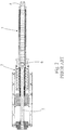
Fig. 1 is a perspective view of a conventional rotary lifting device; -
Fig. 2 is a sectional view of the conventional rotary lifting device; -
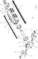
Fig. 3 is a perspective exploded view of a preferred embodiment of the present invention; -
Fig. 4 is a perspective assembled view of the present invention, showing an application embodiment thereof; -
Fig. 5 is a sectional taken along line 5-5 ofFig. 4 ; -
Fig. 6 is a sectional taken along line 6-6 ofFig. 4 ; -
Fig. 7 is a perspective assembled view of the present invention, showing another application embodiment thereof; -
Fig. 8 is a sectional taken along line 8-8 ofFig. 7 ; and -
Fig. 9 is a perspective view of a preferred embodiment of the present invention, showing the operation of a part of the present invention. - Please first refer to
Figs. 3 and4 . According to a preferred embodiment, the linearrotary mechanism 10 of the present invention includes aguide section 20, alinear motor 30, arotary motor 40 and acoupling section 50. - The
guide section 20 has a pair of elongatedstraight guide rails 21 in parallel to each other andmultiple slide blocks 22 slidably disposed on theguide rails 21. Theslide blocks 22 can linearly reciprocally move in the lengthwise direction of theguide rails 21. - The
linear motor 30 has a tubularprimary side 31 with a rectangular outer configuration and a circular inner configuration. Theprimary side 31 is positioned between theguide rails 21 with its axis parallel to the lengthwise direction of theguide rails 21. Theprimary side 31 is directly or indirectly connected with theslide blocks 22, whereby the tubularprimary side 31 is slidably disposed between theguide rails 21 via theslide blocks 22. Thelinear motor 30 further has a shaft-shapedsecondary side 32 coaxially extending into the internal hole of the tubularprimary side 31. Thesecondary side 32 can linearly reciprocally move in its axial direction along the tubularprimary side 31. Anend piece 33 with a certain configuration is fixedly bridged between first ends of theguide rails 21 and pivotally connected with first end of the shaft-shapedsecondary side 32. Accordingly, the shaft-shapedsecondary side 32 is supported by theend piece 33 to self-rotate. Aconnection ring 34 is coaxial ly disposed at second end of the shaft-shapedsecondary side 32 to radially protrude therefrom. In the case that the tubularprimary side 31 is indirectly connected wit theslide blocks 22, certain radiating fins or a cooling module can be sandwiched between theslide blocks 22 and the tubularprimary side 31 so as to dissipate the heat generated by the tubularprimary side 31 in operation and lower the temperature thereof. - The
rotary motor 40 is fixedly bridged between second ends of theguide rails 21 and fixedly connected with the second end of the shaft-shapedsecondary side 32 via theconnection ring 34. Accordingly, therotary motor 40 can linearly reciprocally move along the tubularprimary side 31 in synchronism with the shaft-shapedsecondary side 32 and theguide rails 21. - The
rotary motor 40 is directly fixedly connected on the shaft-shapedsecondary side 32 and is axially linearly reciprocally movable along the tubularprimary side 31 in synchronism with the shaft-shapedsecondary side 32. Therefore, it is unnecessary to additionally increase the length of the actuator shaft of the rotary motor as in the conventional device. The relative axial displacement structures of the actuator shaft and the rotary motor permits the power to be transmitted in such a manner that when therotary motor 40 of thelinear rotary mechanism 10 drives the shaft-shapedsecondary side 32 to rotate, the torque applied to the shaft-shapedsecondary side 32 is directly outward transmitted from the shaft-shapedsecondary side 32. Therefore, it is no more necessary to additionally bear the rotational load of the longer actuator shaft of the rotary motor as in the conventional device. Accordingly, the total length and volume of thelinear rotary mechanism 10 can be greatly reduced. Even if it is necessary to increase the travel, thelinear rotary mechanism 10 is free from the shortcoming of the conventional device that the length must be excessively increased. This is beneficial to simplification of components and automation of industries. - Moreover, in addition to the above effect of reduction of total volume, the manner in which the
linear rotary mechanism 10 applies action force to external component can be changed in accordance with practical requirements of industries.Figs. 4 to 6 show an application embodiment of thelinear rotary mechanism 10. In this embodiment, the shaft-shapedsecondary side 32 of thelinear rotary mechanism 10 can linearly reciprocally move and self-rotate at the same time.Fig. 7 shows another application embodiment in which the shaft-shapedsecondary side 32 of thelinear rotary mechanism 10 can only linearly reciprocally move, while therotary motor 40 exerts rotational action force to other transmission components. - To speak more specifically, according to the embodiment as shown in
Figs. 4 to 6 , therotary motor 40 further includes astator section 41 fixedly bridged between the guide rails 21 and arotor section 42 directed to thelinear motor 30 to serve as an output end. The output end is fixedly coaxially connected with theconnection ring 34, whereby therotor section 42 can drive the shaft-shapedsecondary side 32 to synchronously rotate. Also, by means of the connection of theconnection ring 34, therotor section 42 is synchronously linearly reciprocally movable with the shaft-shapedsecondary side 32. - Please further refer to
Figs. 7 and8 . In the other application embodiment, thestator section 41 of therotary motor 40 is fixedly bridged between the guide rails 21. This embodiment is different from the above embodiment in that the output end formed of therotor section 42 is opposite to thelinear motor 30. Instead, the case of thestator section 41 is fixedly connected with theconnection ring 34. In this case, therotary motor 40 is synchronously linearly reciprocally movable with the shaft-shapedsecondary side 32 and therotor section 42 opposite to the shaft-shapedsecondary side 32 exerts rotational action force to an external component on the back of the shaft-shapedsecondary side 32. - Furthermore, in order to facilitate connection between the
rotary motor 40 and the guide rails 21 and change of the relative state between therotary motor 40 and thelinear motor 30, theconnection section 50 is provided to achieve this effect. Please refer toFig. 9 . Theconnection section 50 has two side blocks 51 with a certain configuration. The two side blocks 51 are respectively fixedly disposed on the guide rails 21 to hold two sides of the case of thestator section 41. Tworotary shafts 52 are coaxially oppositely disposed between two sides of the case of thestator section 41 and the two side blocks 51. The axial direction of therotary shafts 52 is normal to the lengthwise direction of the guide rails 21. Accordingly, therotary motor 40 can be rotated around therotary shafts 52 between the guide rails 21 so as to change the corresponding state between the output end of therotor section 42 and thelinear motor 30. Multiple fixingbolts 53 are respectively fixedly connected between the side blocks 51 and the case of thestator section 41 so as to fix and locate therotary motor 40 between the side blocks 51. - The above embodiments are only used to illustrate the present invention, not intended to limit the scope thereof. Many modifications of the above embodiments can be made without departing from the scope of the present invention, which is defined in the appended claims.
Claims (8)
- A linear rotary mechanism (10) comprising:a pair of elongated guide rails (21) in parallel to each other, a linear motor (30) and a rotary motor (40);characterized in thatthe linear motor (30) having a tubular primary side (31) slidably disposed on the guide rails (21) and a shaft-shaped secondary side (32) coaxially extending into an internal hole of the tubular primary side (31), the shaft-shaped secondary side (32) being axially linearly reciprocally movable along the tubular primary side (31); andthe rotary motor (40) fixedly disposed on the guide rails (21) and connected with one end of the shaft-shaped secondary side (32), the rotary motor (40) being linearly reciprocally movable along the tubular primary side (31) in synchronism with the shaft-shaped secondary side (32) and the guide rails (21).
- The linear rotary mechanism (10) as claimed in claim 1, wherein the linear motor (30) further includes an end piece (33) pivotally disposed at a first end of the shaft-shaped secondary side (32) and fixedly bridged between the guide rails (21).
- The linear rotary mechanism (10) as claimed in claim 1, wherein the linear motor (30) further includes a connection ring (34) coaxially disposed at a second end of the shaft-shaped secondary side (32), the linear motor (30) being connected with the rotary motor (40) via the connection ring (34).
- The linear rotary mechanism (10) as claimed in claim 1, wherein the rotary motor (40) further includes a rotor section (42) connected with the second end of the shaft-shaped secondary side (32), whereby the rotor section (42) and the shaft-shaped secondary side (32) can synchronously rotate.
- The linear rotary mechanism (10) as claimed in claim 1, wherein the rotary motor (40) further includes a stator section (41) connected with the second end of the shaft-shaped secondary side (32), whereby the rotary motor (40) is synchronously linearly reciprocally movable with the shaft-shaped secondary side (32).
- The linear rotary mechanism (10) as claimed in claim 1, further comprising a connection section (50) bridged between the rotary motor (40) and the guide rails (21).
- The linear rotary mechanism (10) as claimed in claim 6, wherein the connection section (50) has two side blocks (51) respectively disposed on two sides of the rotary motor (40) and fixedly connected with the adjacent guide rails (21).
- The linear rotary mechanism (10) as claimed in claim 7, wherein the connection section (50) further includes two rotary shafts (52) coaxially oppositely disposed between two sides of the case of the stator section (41) of the rotary motor (40) and the adjacent side blocks (51), the axial direction of the rotary shafts (52) being normal to the lengthwise direction of the guide rails (21), whereby the rotary motor (40) can be rotated around the rotary shafts (52) between the side blocks (51) so as to change the direction of the rotary motor (40) so as to permit the connection of either the rotor section (42) or the stator section (41) of the rotary motor (40) with the second end of the shaft-shaped secondary side (32) of the linear motor (30).
Priority Applications (1)
| Application Number | Priority Date | Filing Date | Title |
|---|---|---|---|
| EP15174826.6A EP3113342B1 (en) | 2015-07-01 | 2015-07-01 | Linear rotary mechanism |
Applications Claiming Priority (1)
| Application Number | Priority Date | Filing Date | Title |
|---|---|---|---|
| EP15174826.6A EP3113342B1 (en) | 2015-07-01 | 2015-07-01 | Linear rotary mechanism |
Publications (2)
| Publication Number | Publication Date |
|---|---|
| EP3113342A1 EP3113342A1 (en) | 2017-01-04 |
| EP3113342B1 true EP3113342B1 (en) | 2018-03-07 |
Family
ID=53540608
Family Applications (1)
| Application Number | Title | Priority Date | Filing Date |
|---|---|---|---|
| EP15174826.6A Active EP3113342B1 (en) | 2015-07-01 | 2015-07-01 | Linear rotary mechanism |
Country Status (1)
| Country | Link |
|---|---|
| EP (1) | EP3113342B1 (en) |
Families Citing this family (1)
| Publication number | Priority date | Publication date | Assignee | Title |
|---|---|---|---|---|
| EP3468009B8 (en) | 2017-10-06 | 2020-12-23 | Memotec GmbH & Co. KG | Rotation stroke module for the rotation and/or linear movement of a work element |
Family Cites Families (5)
| Publication number | Priority date | Publication date | Assignee | Title |
|---|---|---|---|---|
| US5404983A (en) * | 1992-12-14 | 1995-04-11 | Eicher; Fred C. | Turn-act multiaction device |
| DE10025351A1 (en) * | 2000-05-23 | 2001-11-29 | Wittenstein Gmbh & Co Kg | Lift / swivel drive |
| DE102004056209B4 (en) * | 2004-11-22 | 2011-06-01 | Siemens Ag | Linearly displaceable rotary drive for a plastic injection molding machine |
| DE102008037707A1 (en) * | 2008-08-14 | 2010-02-18 | Schaeffler Kg | Drive unit with a first and a second motor |
| US9590471B2 (en) * | 2012-11-16 | 2017-03-07 | Nti Ag | Rotary lifting device |
-
2015
- 2015-07-01 EP EP15174826.6A patent/EP3113342B1/en active Active
Non-Patent Citations (1)
| Title |
|---|
| None * |
Also Published As
| Publication number | Publication date |
|---|---|
| EP3113342A1 (en) | 2017-01-04 |
Similar Documents
| Publication | Publication Date | Title |
|---|---|---|
| US9669767B2 (en) | Vehicle step apparatus | |
| US9677651B2 (en) | Linear actuator | |
| RU2619742C2 (en) | Differential lock with small stroke length and with large length of locking links | |
| US9885345B2 (en) | Scalable multi-element shape memory alloy rotary motor | |
| DE102020209424A1 (en) | Reluctance motor device, reluctance motor with the reluctance motor device and method for cooling a stator unit of the reluctance motor | |
| WO2016156359A3 (en) | Drive unit for a setting device, in particular a rivet setting device | |
| US20130101692A1 (en) | Screw mounting structure of injection molding machine | |
| EP2524741B1 (en) | Device for flanging the end of a metal tube | |
| US9482285B2 (en) | Hybrid torque transmission mechanism | |
| EP3330558A1 (en) | Rotational power transmission mechanism and heat treatment furnace | |
| JP6980841B2 (en) | Vehicle lifting system with compact belt-mounted wave gearing device and compact belt-mounted wave gearing device | |
| US20110232403A1 (en) | Complex reduction mechanism of linear actuator | |
| EP3113342A1 (en) | Linear rotary mechanism | |
| US20160348774A1 (en) | Spring mechanism and linear motion displacement mechanism | |
| CN110266144A (en) | A kind of micro motor assembly and electronic equipment | |
| US9945457B2 (en) | Linear rotary mechanism | |
| CN102795336A (en) | High integrity linear actuator and method of operation | |
| US20050039553A1 (en) | Linear actuator | |
| CN109391118B (en) | Axial rotation linear motor | |
| US20140102231A1 (en) | Threaded rod reciprocation inner rotor direct drive mechanism | |
| KR101403493B1 (en) | Serial Connectable Motor | |
| CN204019530U (en) | Novel three-branched-chainsix-degree-of-freedorobot six-degree-of-freedorobot robot driving mechanism | |
| CN105008647A (en) | Transmission-drive unit and convenience drive with transmission-drive unit | |
| TWI532300B (en) | Linear rotary mechanism | |
| CN116638127A (en) | Adjusting mechanisms and hand-held power tools |
Legal Events
| Date | Code | Title | Description |
|---|---|---|---|
| PUAI | Public reference made under article 153(3) epc to a published international application that has entered the european phase |
Free format text: ORIGINAL CODE: 0009012 |
|
| 17P | Request for examination filed |
Effective date: 20151007 |
|
| AK | Designated contracting states |
Kind code of ref document: A1 Designated state(s): AL AT BE BG CH CY CZ DE DK EE ES FI FR GB GR HR HU IE IS IT LI LT LU LV MC MK MT NL NO PL PT RO RS SE SI SK SM TR |
|
| AX | Request for extension of the european patent |
Extension state: BA ME |
|
| RBV | Designated contracting states (corrected) |
Designated state(s): AL AT BE BG CH CY CZ DE DK EE ES FI FR GB GR HR HU IE IS IT LI LT LU LV MC MK MT NL NO PL PT RO RS SE SI SK SM TR |
|
| RIC1 | Information provided on ipc code assigned before grant |
Ipc: H02K 41/03 20060101AFI20170718BHEP Ipc: H02K 21/24 20060101ALN20170718BHEP Ipc: H02K 16/00 20060101ALI20170718BHEP |
|
| GRAP | Despatch of communication of intention to grant a patent |
Free format text: ORIGINAL CODE: EPIDOSNIGR1 |
|
| RIC1 | Information provided on ipc code assigned before grant |
Ipc: H02K 41/03 20060101AFI20170828BHEP Ipc: H02K 16/00 20060101ALI20170828BHEP Ipc: H02K 21/24 20060101ALN20170828BHEP |
|
| INTG | Intention to grant announced |
Effective date: 20170919 |
|
| GRAS | Grant fee paid |
Free format text: ORIGINAL CODE: EPIDOSNIGR3 |
|
| GRAA | (expected) grant |
Free format text: ORIGINAL CODE: 0009210 |
|
| AK | Designated contracting states |
Kind code of ref document: B1 Designated state(s): AL AT BE BG CH CY CZ DE DK EE ES FI FR GB GR HR HU IE IS IT LI LT LU LV MC MK MT NL NO PL PT RO RS SE SI SK SM TR |
|
| REG | Reference to a national code |
Ref country code: GB Ref legal event code: FG4D |
|
| REG | Reference to a national code |
Ref country code: CH Ref legal event code: EP Ref country code: AT Ref legal event code: REF Ref document number: 977550 Country of ref document: AT Kind code of ref document: T Effective date: 20180315 |
|
| REG | Reference to a national code |
Ref country code: IE Ref legal event code: FG4D |
|
| REG | Reference to a national code |
Ref country code: DE Ref legal event code: R096 Ref document number: 602015008541 Country of ref document: DE |
|
| REG | Reference to a national code |
Ref country code: NL Ref legal event code: MP Effective date: 20180307 |
|
| REG | Reference to a national code |
Ref country code: LT Ref legal event code: MG4D |
|
| PG25 | Lapsed in a contracting state [announced via postgrant information from national office to epo] |
Ref country code: NO Free format text: LAPSE BECAUSE OF FAILURE TO SUBMIT A TRANSLATION OF THE DESCRIPTION OR TO PAY THE FEE WITHIN THE PRESCRIBED TIME-LIMIT Effective date: 20180607 Ref country code: CY Free format text: LAPSE BECAUSE OF FAILURE TO SUBMIT A TRANSLATION OF THE DESCRIPTION OR TO PAY THE FEE WITHIN THE PRESCRIBED TIME-LIMIT Effective date: 20180307 Ref country code: FI Free format text: LAPSE BECAUSE OF FAILURE TO SUBMIT A TRANSLATION OF THE DESCRIPTION OR TO PAY THE FEE WITHIN THE PRESCRIBED TIME-LIMIT Effective date: 20180307 Ref country code: ES Free format text: LAPSE BECAUSE OF FAILURE TO SUBMIT A TRANSLATION OF THE DESCRIPTION OR TO PAY THE FEE WITHIN THE PRESCRIBED TIME-LIMIT Effective date: 20180307 Ref country code: HR Free format text: LAPSE BECAUSE OF FAILURE TO SUBMIT A TRANSLATION OF THE DESCRIPTION OR TO PAY THE FEE WITHIN THE PRESCRIBED TIME-LIMIT Effective date: 20180307 Ref country code: LT Free format text: LAPSE BECAUSE OF FAILURE TO SUBMIT A TRANSLATION OF THE DESCRIPTION OR TO PAY THE FEE WITHIN THE PRESCRIBED TIME-LIMIT Effective date: 20180307 |
|
| REG | Reference to a national code |
Ref country code: AT Ref legal event code: MK05 Ref document number: 977550 Country of ref document: AT Kind code of ref document: T Effective date: 20180307 |
|
| PG25 | Lapsed in a contracting state [announced via postgrant information from national office to epo] |
Ref country code: GR Free format text: LAPSE BECAUSE OF FAILURE TO SUBMIT A TRANSLATION OF THE DESCRIPTION OR TO PAY THE FEE WITHIN THE PRESCRIBED TIME-LIMIT Effective date: 20180608 Ref country code: LV Free format text: LAPSE BECAUSE OF FAILURE TO SUBMIT A TRANSLATION OF THE DESCRIPTION OR TO PAY THE FEE WITHIN THE PRESCRIBED TIME-LIMIT Effective date: 20180307 Ref country code: SE Free format text: LAPSE BECAUSE OF FAILURE TO SUBMIT A TRANSLATION OF THE DESCRIPTION OR TO PAY THE FEE WITHIN THE PRESCRIBED TIME-LIMIT Effective date: 20180307 Ref country code: BG Free format text: LAPSE BECAUSE OF FAILURE TO SUBMIT A TRANSLATION OF THE DESCRIPTION OR TO PAY THE FEE WITHIN THE PRESCRIBED TIME-LIMIT Effective date: 20180607 Ref country code: RS Free format text: LAPSE BECAUSE OF FAILURE TO SUBMIT A TRANSLATION OF THE DESCRIPTION OR TO PAY THE FEE WITHIN THE PRESCRIBED TIME-LIMIT Effective date: 20180307 |
|
| PG25 | Lapsed in a contracting state [announced via postgrant information from national office to epo] |
Ref country code: NL Free format text: LAPSE BECAUSE OF FAILURE TO SUBMIT A TRANSLATION OF THE DESCRIPTION OR TO PAY THE FEE WITHIN THE PRESCRIBED TIME-LIMIT Effective date: 20180307 Ref country code: EE Free format text: LAPSE BECAUSE OF FAILURE TO SUBMIT A TRANSLATION OF THE DESCRIPTION OR TO PAY THE FEE WITHIN THE PRESCRIBED TIME-LIMIT Effective date: 20180307 Ref country code: RO Free format text: LAPSE BECAUSE OF FAILURE TO SUBMIT A TRANSLATION OF THE DESCRIPTION OR TO PAY THE FEE WITHIN THE PRESCRIBED TIME-LIMIT Effective date: 20180307 Ref country code: AL Free format text: LAPSE BECAUSE OF FAILURE TO SUBMIT A TRANSLATION OF THE DESCRIPTION OR TO PAY THE FEE WITHIN THE PRESCRIBED TIME-LIMIT Effective date: 20180307 Ref country code: PL Free format text: LAPSE BECAUSE OF FAILURE TO SUBMIT A TRANSLATION OF THE DESCRIPTION OR TO PAY THE FEE WITHIN THE PRESCRIBED TIME-LIMIT Effective date: 20180307 |
|
| PG25 | Lapsed in a contracting state [announced via postgrant information from national office to epo] |
Ref country code: CZ Free format text: LAPSE BECAUSE OF FAILURE TO SUBMIT A TRANSLATION OF THE DESCRIPTION OR TO PAY THE FEE WITHIN THE PRESCRIBED TIME-LIMIT Effective date: 20180307 Ref country code: SK Free format text: LAPSE BECAUSE OF FAILURE TO SUBMIT A TRANSLATION OF THE DESCRIPTION OR TO PAY THE FEE WITHIN THE PRESCRIBED TIME-LIMIT Effective date: 20180307 Ref country code: SM Free format text: LAPSE BECAUSE OF FAILURE TO SUBMIT A TRANSLATION OF THE DESCRIPTION OR TO PAY THE FEE WITHIN THE PRESCRIBED TIME-LIMIT Effective date: 20180307 Ref country code: AT Free format text: LAPSE BECAUSE OF FAILURE TO SUBMIT A TRANSLATION OF THE DESCRIPTION OR TO PAY THE FEE WITHIN THE PRESCRIBED TIME-LIMIT Effective date: 20180307 |
|
| REG | Reference to a national code |
Ref country code: DE Ref legal event code: R097 Ref document number: 602015008541 Country of ref document: DE |
|
| PG25 | Lapsed in a contracting state [announced via postgrant information from national office to epo] |
Ref country code: PT Free format text: LAPSE BECAUSE OF FAILURE TO SUBMIT A TRANSLATION OF THE DESCRIPTION OR TO PAY THE FEE WITHIN THE PRESCRIBED TIME-LIMIT Effective date: 20180709 |
|
| PLBE | No opposition filed within time limit |
Free format text: ORIGINAL CODE: 0009261 |
|
| STAA | Information on the status of an ep patent application or granted ep patent |
Free format text: STATUS: NO OPPOSITION FILED WITHIN TIME LIMIT |
|
| PG25 | Lapsed in a contracting state [announced via postgrant information from national office to epo] |
Ref country code: DK Free format text: LAPSE BECAUSE OF FAILURE TO SUBMIT A TRANSLATION OF THE DESCRIPTION OR TO PAY THE FEE WITHIN THE PRESCRIBED TIME-LIMIT Effective date: 20180307 |
|
| 26N | No opposition filed |
Effective date: 20181210 |
|
| PG25 | Lapsed in a contracting state [announced via postgrant information from national office to epo] |
Ref country code: SI Free format text: LAPSE BECAUSE OF FAILURE TO SUBMIT A TRANSLATION OF THE DESCRIPTION OR TO PAY THE FEE WITHIN THE PRESCRIBED TIME-LIMIT Effective date: 20180307 |
|
| REG | Reference to a national code |
Ref country code: CH Ref legal event code: PL |
|
| PG25 | Lapsed in a contracting state [announced via postgrant information from national office to epo] |
Ref country code: LU Free format text: LAPSE BECAUSE OF NON-PAYMENT OF DUE FEES Effective date: 20180701 Ref country code: MC Free format text: LAPSE BECAUSE OF FAILURE TO SUBMIT A TRANSLATION OF THE DESCRIPTION OR TO PAY THE FEE WITHIN THE PRESCRIBED TIME-LIMIT Effective date: 20180307 |
|
| REG | Reference to a national code |
Ref country code: BE Ref legal event code: MM Effective date: 20180731 |
|
| REG | Reference to a national code |
Ref country code: IE Ref legal event code: MM4A |
|
| PG25 | Lapsed in a contracting state [announced via postgrant information from national office to epo] |
Ref country code: LI Free format text: LAPSE BECAUSE OF NON-PAYMENT OF DUE FEES Effective date: 20180731 Ref country code: CH Free format text: LAPSE BECAUSE OF NON-PAYMENT OF DUE FEES Effective date: 20180731 Ref country code: FR Free format text: LAPSE BECAUSE OF NON-PAYMENT OF DUE FEES Effective date: 20180731 Ref country code: IE Free format text: LAPSE BECAUSE OF NON-PAYMENT OF DUE FEES Effective date: 20180701 |
|
| PG25 | Lapsed in a contracting state [announced via postgrant information from national office to epo] |
Ref country code: BE Free format text: LAPSE BECAUSE OF NON-PAYMENT OF DUE FEES Effective date: 20180731 |
|
| PG25 | Lapsed in a contracting state [announced via postgrant information from national office to epo] |
Ref country code: MT Free format text: LAPSE BECAUSE OF NON-PAYMENT OF DUE FEES Effective date: 20180701 |
|
| GBPC | Gb: european patent ceased through non-payment of renewal fee |
Effective date: 20190701 |
|
| PG25 | Lapsed in a contracting state [announced via postgrant information from national office to epo] |
Ref country code: TR Free format text: LAPSE BECAUSE OF FAILURE TO SUBMIT A TRANSLATION OF THE DESCRIPTION OR TO PAY THE FEE WITHIN THE PRESCRIBED TIME-LIMIT Effective date: 20180307 |
|
| PG25 | Lapsed in a contracting state [announced via postgrant information from national office to epo] |
Ref country code: GB Free format text: LAPSE BECAUSE OF NON-PAYMENT OF DUE FEES Effective date: 20190701 |
|
| PG25 | Lapsed in a contracting state [announced via postgrant information from national office to epo] |
Ref country code: HU Free format text: LAPSE BECAUSE OF FAILURE TO SUBMIT A TRANSLATION OF THE DESCRIPTION OR TO PAY THE FEE WITHIN THE PRESCRIBED TIME-LIMIT; INVALID AB INITIO Effective date: 20150701 Ref country code: MK Free format text: LAPSE BECAUSE OF NON-PAYMENT OF DUE FEES Effective date: 20180307 |
|
| PG25 | Lapsed in a contracting state [announced via postgrant information from national office to epo] |
Ref country code: IS Free format text: LAPSE BECAUSE OF FAILURE TO SUBMIT A TRANSLATION OF THE DESCRIPTION OR TO PAY THE FEE WITHIN THE PRESCRIBED TIME-LIMIT Effective date: 20180707 |
|
| PGFP | Annual fee paid to national office [announced via postgrant information from national office to epo] |
Ref country code: DE Payment date: 20250729 Year of fee payment: 11 |
|
| PGFP | Annual fee paid to national office [announced via postgrant information from national office to epo] |
Ref country code: IT Payment date: 20250721 Year of fee payment: 11 |