EP3113338A1 - Dynamoelectric machine main lead servicing - Google Patents
Dynamoelectric machine main lead servicing Download PDFInfo
- Publication number
- EP3113338A1 EP3113338A1 EP16176557.3A EP16176557A EP3113338A1 EP 3113338 A1 EP3113338 A1 EP 3113338A1 EP 16176557 A EP16176557 A EP 16176557A EP 3113338 A1 EP3113338 A1 EP 3113338A1
- Authority
- EP
- European Patent Office
- Prior art keywords
- main lead
- main
- winding
- terminal
- lead
- Prior art date
- Legal status (The legal status is an assumption and is not a legal conclusion. Google has not performed a legal analysis and makes no representation as to the accuracy of the status listed.)
- Withdrawn
Links
- 238000004804 winding Methods 0.000 claims abstract description 95
- 238000000034 method Methods 0.000 claims abstract description 80
- 238000009413 insulation Methods 0.000 claims abstract description 57
- 238000001816 cooling Methods 0.000 claims abstract description 29
- 238000005219 brazing Methods 0.000 claims description 33
- IJGRMHOSHXDMSA-UHFFFAOYSA-N Atomic nitrogen Chemical compound N#N IJGRMHOSHXDMSA-UHFFFAOYSA-N 0.000 claims description 8
- CURLTUGMZLYLDI-UHFFFAOYSA-N Carbon dioxide Chemical compound O=C=O CURLTUGMZLYLDI-UHFFFAOYSA-N 0.000 claims description 8
- 239000012809 cooling fluid Substances 0.000 claims description 7
- 239000007788 liquid Substances 0.000 claims description 6
- 230000000903 blocking effect Effects 0.000 claims description 5
- 229910002092 carbon dioxide Inorganic materials 0.000 claims description 4
- 239000001569 carbon dioxide Substances 0.000 claims description 4
- 238000005520 cutting process Methods 0.000 claims description 4
- 229910052757 nitrogen Inorganic materials 0.000 claims description 4
- 239000007789 gas Substances 0.000 claims description 2
- 230000000977 initiatory effect Effects 0.000 claims description 2
- 230000000717 retained effect Effects 0.000 claims 1
- 238000013459 approach Methods 0.000 abstract description 10
- RYGMFSIKBFXOCR-UHFFFAOYSA-N Copper Chemical compound [Cu] RYGMFSIKBFXOCR-UHFFFAOYSA-N 0.000 description 11
- 229910052802 copper Inorganic materials 0.000 description 11
- 239000010949 copper Substances 0.000 description 11
- 230000006698 induction Effects 0.000 description 10
- 238000010586 diagram Methods 0.000 description 4
- 239000012212 insulator Substances 0.000 description 4
- 238000013021 overheating Methods 0.000 description 4
- 238000004140 cleaning Methods 0.000 description 2
- 239000004744 fabric Substances 0.000 description 2
- 238000005242 forging Methods 0.000 description 2
- 239000000463 material Substances 0.000 description 2
- 239000010445 mica Substances 0.000 description 2
- 229910052618 mica group Inorganic materials 0.000 description 2
- 238000012546 transfer Methods 0.000 description 2
- XLYOFNOQVPJJNP-UHFFFAOYSA-N water Substances O XLYOFNOQVPJJNP-UHFFFAOYSA-N 0.000 description 2
- 229910000831 Steel Inorganic materials 0.000 description 1
- 230000000295 complement effect Effects 0.000 description 1
- 239000004020 conductor Substances 0.000 description 1
- 238000013461 design Methods 0.000 description 1
- 230000000694 effects Effects 0.000 description 1
- 230000005611 electricity Effects 0.000 description 1
- 239000002184 metal Substances 0.000 description 1
- 229910052751 metal Inorganic materials 0.000 description 1
- 238000005498 polishing Methods 0.000 description 1
- 238000012805 post-processing Methods 0.000 description 1
- 238000009991 scouring Methods 0.000 description 1
- 239000007787 solid Substances 0.000 description 1
- 238000003892 spreading Methods 0.000 description 1
- 239000010959 steel Substances 0.000 description 1
- 210000002268 wool Anatomy 0.000 description 1
Images



Classifications
-
- H—ELECTRICITY
- H02—GENERATION; CONVERSION OR DISTRIBUTION OF ELECTRIC POWER
- H02K—DYNAMO-ELECTRIC MACHINES
- H02K15/00—Processes or apparatus specially adapted for manufacturing, assembling, maintaining or repairing of dynamo-electric machines
- H02K15/02—Processes or apparatus specially adapted for manufacturing, assembling, maintaining or repairing of dynamo-electric machines of stator or rotor bodies
-
- H—ELECTRICITY
- H02—GENERATION; CONVERSION OR DISTRIBUTION OF ELECTRIC POWER
- H02K—DYNAMO-ELECTRIC MACHINES
- H02K3/00—Details of windings
- H02K3/46—Fastening of windings on the stator or rotor structure
- H02K3/50—Fastening of winding heads, equalising connectors, or connections thereto
- H02K3/51—Fastening of winding heads, equalising connectors, or connections thereto applicable to rotors only
-
- H—ELECTRICITY
- H02—GENERATION; CONVERSION OR DISTRIBUTION OF ELECTRIC POWER
- H02K—DYNAMO-ELECTRIC MACHINES
- H02K15/00—Processes or apparatus specially adapted for manufacturing, assembling, maintaining or repairing of dynamo-electric machines
- H02K15/50—Disassembling, repairing or modifying dynamo-electric machines
Definitions
- the subject matter disclosed herein relates to dynamoelectric machines. More particularly, the subject matter disclosed herein relates to apparatuses and approaches for repairing/servicing main leads in dynamoelectric machines.
- Dynamoelectric machine (e.g., generator) rotors are commonly called “fields,” and have an electrical connection known as the main lead, which completes the electrical connection between the machine's collector rings and the field winding.
- the main lead (connection) includes a flexible connector composed of numerous thin copper leaves. During operation, these leaves can be damaged, e.g., by fracture, breakage, and/or spreading. This damage can decrease the load carrying capacity of the connector and/or ground the field winding against the field forging, calling for repair.
- repairing the connector involves disassembling the innermost (No. 1) coil winding, which provides access to the terminal stud in the field winding.
- its retaining rings In order to access and remove the innermost coil winding, its retaining rings must also be removed. Following removal of the innermost coil winding, the terminal stud (and related assembly) is replaced.
- This conventional process requires a significant labor force to remove/reinstall the retaining rings, disassemble/assemble the coil winding (including removing insulation and re-insulating), and replace the terminal stud. For example, in some generators, this process can take between four (4) and five (5) working days. Additionally, this conventional process involves purchasing various new parts, including insulation, terminal studs, etc. Further, removing the innermost coil winding may cause damage to ancillary components (e.g., slot armor), incurring additional cost.
- ancillary components e.g., slot armor
- Various embodiments of the disclosure include approaches for servicing a main lead in a dynamoelectric machine.
- Some embodiments include a method of servicing a main lead in a dynamoelectric machine rotor having a collector end retaining ring retaining the main lead, a terminal stud contacting the main lead, a winding contacting the main lead, and main terminal insulation proximate the main lead, the method including: removing the collector end retaining ring to expose the main lead; disconnecting the main lead from each of the winding and the terminal stud, during the disconnecting of the main lead from the terminal stud, cooling the main terminal insulation proximate the main lead; connecting a replacement main lead to each of the winding and the terminal stud; and during the connecting of the replacement main lead to the terminal stud, cooling the main terminal insulation proximate the main lead.
- a first aspect of the invention includes a method of servicing a main lead in a dynamoelectric machine rotor having a collector end retaining ring retaining the main lead, a terminal stud contacting the main lead, a winding contacting the main lead, and main terminal insulation proximate the main lead, the method including: removing the collector end retaining ring to expose the main lead; disconnecting the main lead from each of the winding and the terminal stud, during the disconnecting of the main lead from the terminal stud, cooling the main terminal insulation proximate the main lead; connecting a replacement main lead to each of the winding and the terminal stud; and during the connecting of the replacement main lead to the terminal stud, cooling the main terminal insulation proximate the main lead.
- a second aspect of the invention includes a method of servicing a main lead in a dynamoelectric machine rotor having a collector end retaining ring retaining the main lead, a terminal stud contacting the main lead, a winding contacting the main lead, and main terminal insulation proximate the main lead, the method including: removing the collector end retaining ring to expose the main lead; disconnecting the main lead from each of the winding and the terminal stud by at least one of cutting or un-brazing the main lead from each of the winding and the terminal stud; during the disconnecting of the main lead from the terminal stud, cooling the main terminal insulation proximate the main lead; connecting a replacement main lead or a refurbished main lead to each of the winding and the terminal stud; and during the connecting of the replacement main lead to the terminal stud, cooling the main terminal insulation proximate the main lead.
- a third aspect of the invention includes a method of servicing a main lead in a dynamoelectric machine rotor having a collector end retaining ring retaining the main lead, a terminal stud contacting the main lead, a winding contacting the main lead, and main terminal insulation proximate the main lead, the method including: removing the collector end retaining ring to expose the main lead; un-brazing the main lead from each of the winding and the terminal stud; cooling the main terminal insulation proximate the main lead to control a temperature of the main terminal insulation before, during and after the un-brazing of the main lead from the terminal stud; brazing a connection between a replacement main lead or a refurbished main lead to each of the winding and the terminal stud; and cooling the main terminal insulation proximate the main lead to control a temperature of the main terminal insulation before, during and after the brazing of the connection between the replacement main lead or the refurbished main lead to the terminal stud.
- the subject matter disclosed herein relates to dynamoelectric machines. More particularly, the subject matter disclosed herein relates to apparatuses and approaches for repairing main leads in dynamoelectric machines.
- various aspects of the disclosure include approaches for repairing the main lead (or, "connector,” including flexible leaves) without removing the innermost coil winding in a dynamoelectric machine (generator).
- two major issues have prevented repairing the flexible leaves of the main lead, without removing the innermost coil winding (No. 1 coil).
- the available space for servicing is very limited, e.g., space between the winding and rotor body can be as small as, e.g., 2.5 inches ( ⁇ 6.3 centimeters (cm)) axially, and 1.5 inches ( ⁇ 3.75 cm) radially.
- repairing the main lead requires un-brazing and re-brazing components proximate the insulation for the terminal stud.
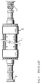
- FIG. 1 there is illustrated a dynamoelectric machine rotor 1, such as a generator rotor, according to the prior art.
- the rotor 1 includes end shafts 2 one of which contain insulated conductors, i.e., bore connectors or "bore copper" that extend longitudinally along the end shafts 2 between the exciter/slip rings 3 and the rotor field windings located on the rotor within the retaining rings 4.
- the rotor 1 includes a series of longitudinally extending, radially-opening slots, not shown, having dovetail-shaped, longitudinal grooves in the slot sides adjacent the periphery of the rotor 1.
- Field windings are inserted in the slots and extend the length of the rotor body with longitudinal wedges, not shown, located in the dovetail-shaped grooves for holding the windings in place against centrifugal forces exerted when the rotor 1 is at operational speed.
- the longitudinal sections of the windings extend in an axial direction beyond the ends of the larger diameter portion of the rotor and include field windings (end turns) 7 ( FIG. 2 ) for connecting a longitudinal section of one slot with a winding of another slot.
- the retaining ring 4 overlies these windings (end turns) 7 and resists the centrifugal forces on the winding end turns when the rotor 1 is at operational speed so as to restrain the end turns from moving in a radially-outwardly direction.
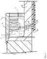
- a terminal stud 9 extends between a bore copper 10 and the field windings 7.
- a flexible main lead (or, lead connector) 8 typically connects the radial outer end of the terminal stud 9 to an end turn 7.
- the bore copper 10 is electrically insulated from the rotor 2, for example, by insulation 12.
- the terminal stud 9, while conducting electricity between the bore copper 10 and windings 7, is likewise electrically insulated from the rotor 1 in a conventional manner (insulation 12A).
- the radial opening in the bore copper 10 which receives the lower or inner end of the terminal stud 9 is a tapered, threaded aperture which receives complementary threads on the end of the terminal stud.
- FIG. 3 shows a flow diagram illustrating processes in a method according to various embodiments.
- FIGS. 4-6 show three-dimensional schematic depictions of a portion of dynamoelectric machine rotor 1, undergoing processes according to the flow diagram in FIG. 3 .
- the rotor 1 can include a collector end retaining ring (retaining ring) 4 retaining the main lead 8, terminal stud 9 contacting the main lead 8, and main terminal insulation (insulation 12) proximate the main lead 8.
- a method is disclosed including the following processes:
- process P2 can further include disconnecting main lead 8 from terminal stud 9, and in particular embodiments, main lead 8 is disconnected from terminal stud 9 after disconnecting main lead 8 from winding 7. In some embodiments, this can include un-brazing the connection between the main lead 8 and the terminal stud 9.
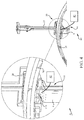
- FIG. 5 shows a three-dimensional perspective view of an example induction wand 32, which may be used to perform the un-brazing operation in process P2.
- the induction wand 32 can be shaped to be inserted in the axial gap 30 behind the innermost coil winding 7, and positioned inside of the terminal stud bore 34 (shown perhaps more clearly in FIG. 6 ), with concentrators 36 focusing the induction field on the two exposed sides of the terminal stud 9.
- This configuration can apply heat directly to terminal stud 9, and not to the adjacent (and thinner) copper leaves 38 of main lead 8, as the heat could damage those copper leaves 38.
- the flexible main lead 8 can be disconnected from terminal stud 9 using any mechanical approach, e.g., a clamp, pliers, etc.
- the induction wand 32 can be clamped proximate terminal stud 9, e.g., using a wedge-based clamping system 33.
- the wedge-based clamping system 33 can include at least one wedge member 35 (several shown) inserted in the terminal stud bore 34 and contacting at least one of a sidewall 37 of the bore 34 and induction wand 32, retaining the induction wand 32 against the joint between main lead 8 and terminal stud 9.
- the process of disconnecting the main lead 8 from winding 7 and/or disconnecting main lead 8 from terminal stud 9 can be performed by cutting main lead 8 from winding 7 and/or cutting the main lead 8 from the terminal stud 9 using a saw, e.g., a precision metal saw. It is understood that this process can be performed in conjunction with use of a braze wand 28 or induction wand 32 (as described herein), or may be performed as an alternative process. In some cases, regardless of the method used to disconnect main lead 8 from winding 7 and terminal stud 9, the process can include cleaning and preparing the joint surfaces proximate the joints between main lead 8 and winding 7 and terminal stud 9, respectively.
- This process can also include removing any damaged insulation 12A proximate the un-brazed joint.
- Process P2A during process P2 (e.g., and in some cases, prior, during, and after disconnecting of main lead 8 from winding 7 and/or disconnecting main lead 8 from terminal stud 9) the method can include cooling main terminal insulation 12A proximate main lead 8 to prevent overheating of that insulation 12A.
- Main terminal insulation 12A is in place to prevent electrical creepage paths from developing between the forging or terminal nut and main lead 8, forcing grounding of the winding. Because this insulation cannot be replaced without removing the innermost coil winding 7 (and removing the main lead 8), various embodiments include methods for preventing damage to the main terminal insulation 12A.
- cooling main terminal insulation 12A can include positioning a cooling apparatus 40 ( FIGS.
- the cooling apparatus 40 includes one of a liquid nitrogen apparatus configured to initiate flow of a liquid nitrogen cooling fluid, or a dry carbon-dioxide apparatus configured to initiate flow of a (dry) carbon-dioxide gas.
- the cooling apparatus 40 includes a cooling fluid reservoir/generator 42, and a nozzle 44 fluidly connected with the reservoir/generator 42 for delivering the cooling fluid to main terminal insulation 12A when initiated.
- nozzle 44 can have a helical shape including impinging apertures along its exterior (at the helical-shaped portion), for distributing the cooling fluid within the desired area of cooling proximate main terminal insulation 12A.
- the nozzle is positioned proximate the main terminal insulation 12A prior to disconnecting main lead 8 from winding 7, and remains in position after the winding 7 has been disconnected from main lead 8.
- a subsequent process can include connecting a replacement main lead 8 or a refurbished main lead 8 to each of the winding 7 and the terminal stud 9.
- the refurbished main lead 8 can include the main lead which was disconnected in process P2 (e.g., main lead 8), while replacement main lead 8 is a distinct main lead than main lead 8 disconnected in process P2. It is understood that a replacement main lead may be preferable in cases where the original main lead is damaged beyond repair.
- connecting a replacement main lead 8 or a refurbished main lead 8 to winding 7 and terminal stud 9 includes brazing a connection between the main lead 8 and the winding 7 and brazing a connection between the main lead 8 and the terminal stud 9.
- brazing processes can be performed in a substantially similar manner as the un-brazing processes described with respect to process P2, that is, positioning braze wand 32 and subsequently brazing connection between main lead 8 and terminal stud 9, and positioning induction wand 28 and subsequently brazing connection between main lead 8 and winding 7.
- a wedge may be placed between the bottom turn 26 and its adjacent turn to physically separate those turns, and an insulator (e.g., a piece of mica or comparable material) can also be placed between the turns to prevent heat transfer damage to the adjacent turn.
- the corner at the side of winding 7 can be wrapped in a damp insulator (e.g., liquid (e.g., water) soaked cloth) to prevent over-heating and un-brazing winding 7.
- Process P3A during process P3 (e.g., and in some cases, prior, during, and after) connecting of (replacement) main lead 8 or (refurbished) main lead 8 from the winding 7 and/or disconnecting main lead 8 from terminal stud 9) the method includes cooling the main terminal insulation 12 proximate the main lead 8 to prevent overheating of that insulation 12.
- This cooling process can be substantially similar to the process described with respect to Process P2A, e.g., using cooling apparatus 40.
- the disconnecting of main lead 8 and the connecting of the replacement main lead 8 (or refurbished main lead 8) are performed without removing innermost coil winding 26. These processes can reduce down time and mitigate damage to components in dynamoelectric machine 1.
- additional post-processing can include re-installing collector end retaining ring 4 ( FIG. 1 ).
- this process can also include re-installing amortisseur winding 20 (along with retaining ring insulation) and blocking 22 for innermost coil winding 24. These processes can be performed similarly as described with respect to process P1.
- the technical effect of the various embodiments of the disclosure includes, e.g., repairing a dynamoelectric machine (e.g., generator) main lead.
- a dynamoelectric machine e.g., generator
Landscapes
- Engineering & Computer Science (AREA)
- Power Engineering (AREA)
- Manufacturing & Machinery (AREA)
- Manufacture Of Motors, Generators (AREA)
Abstract
Various embodiments include approaches for servicing a dynamoelectric machine main lead (8). Some embodiments include a method of servicing a main lead (8) in a dynamoelectric machine rotor (1) having a collector end retaining ring (4) retaining the main lead (8), a terminal stud (9) contacting the main lead (8), a winding contacting the main lead (8), and main terminal insulation (12A) proximate the main lead (8), the method including: removing the collector end retaining ring (4) to expose the main lead (8); disconnecting the main lead (8) from each of the winding and the terminal stud (9), during the disconnecting of the main lead (8) from the terminal stud (9), cooling the main terminal insulation (12A) proximate the main lead (8); connecting a replacement main lead (8) to each of the winding and the terminal stud (9); and during the connecting of the replacement main lead (8) to the terminal stud (9), cooling the main terminal insulation (12A) proximate the main lead (8).
Description
- The subject matter disclosed herein relates to dynamoelectric machines. More particularly, the subject matter disclosed herein relates to apparatuses and approaches for repairing/servicing main leads in dynamoelectric machines.
- Dynamoelectric machine (e.g., generator) rotors are commonly called "fields," and have an electrical connection known as the main lead, which completes the electrical connection between the machine's collector rings and the field winding. On some generator fields, for example, mid-sized generator fields, the main lead (connection) includes a flexible connector composed of numerous thin copper leaves. During operation, these leaves can be damaged, e.g., by fracture, breakage, and/or spreading. This damage can decrease the load carrying capacity of the connector and/or ground the field winding against the field forging, calling for repair.
- Conventionally, repairing the connector involves disassembling the innermost (No. 1) coil winding, which provides access to the terminal stud in the field winding. In order to access and remove the innermost coil winding, its retaining rings must also be removed. Following removal of the innermost coil winding, the terminal stud (and related assembly) is replaced. This conventional process requires a significant labor force to remove/reinstall the retaining rings, disassemble/assemble the coil winding (including removing insulation and re-insulating), and replace the terminal stud. For example, in some generators, this process can take between four (4) and five (5) working days. Additionally, this conventional process involves purchasing various new parts, including insulation, terminal studs, etc. Further, removing the innermost coil winding may cause damage to ancillary components (e.g., slot armor), incurring additional cost.
- Various embodiments of the disclosure include approaches for servicing a main lead in a dynamoelectric machine. Some embodiments include a method of servicing a main lead in a dynamoelectric machine rotor having a collector end retaining ring retaining the main lead, a terminal stud contacting the main lead, a winding contacting the main lead, and main terminal insulation proximate the main lead, the method including: removing the collector end retaining ring to expose the main lead; disconnecting the main lead from each of the winding and the terminal stud, during the disconnecting of the main lead from the terminal stud, cooling the main terminal insulation proximate the main lead; connecting a replacement main lead to each of the winding and the terminal stud; and during the connecting of the replacement main lead to the terminal stud, cooling the main terminal insulation proximate the main lead.
- A first aspect of the invention includes a method of servicing a main lead in a dynamoelectric machine rotor having a collector end retaining ring retaining the main lead, a terminal stud contacting the main lead, a winding contacting the main lead, and main terminal insulation proximate the main lead, the method including: removing the collector end retaining ring to expose the main lead; disconnecting the main lead from each of the winding and the terminal stud, during the disconnecting of the main lead from the terminal stud, cooling the main terminal insulation proximate the main lead; connecting a replacement main lead to each of the winding and the terminal stud; and during the connecting of the replacement main lead to the terminal stud, cooling the main terminal insulation proximate the main lead.
- A second aspect of the invention includes a method of servicing a main lead in a dynamoelectric machine rotor having a collector end retaining ring retaining the main lead, a terminal stud contacting the main lead, a winding contacting the main lead, and main terminal insulation proximate the main lead, the method including: removing the collector end retaining ring to expose the main lead; disconnecting the main lead from each of the winding and the terminal stud by at least one of cutting or un-brazing the main lead from each of the winding and the terminal stud; during the disconnecting of the main lead from the terminal stud, cooling the main terminal insulation proximate the main lead; connecting a replacement main lead or a refurbished main lead to each of the winding and the terminal stud; and during the connecting of the replacement main lead to the terminal stud, cooling the main terminal insulation proximate the main lead.
- A third aspect of the invention includes a method of servicing a main lead in a dynamoelectric machine rotor having a collector end retaining ring retaining the main lead, a terminal stud contacting the main lead, a winding contacting the main lead, and main terminal insulation proximate the main lead, the method including: removing the collector end retaining ring to expose the main lead; un-brazing the main lead from each of the winding and the terminal stud; cooling the main terminal insulation proximate the main lead to control a temperature of the main terminal insulation before, during and after the un-brazing of the main lead from the terminal stud; brazing a connection between a replacement main lead or a refurbished main lead to each of the winding and the terminal stud; and cooling the main terminal insulation proximate the main lead to control a temperature of the main terminal insulation before, during and after the brazing of the connection between the replacement main lead or the refurbished main lead to the terminal stud.
- These and other features of this invention will be more readily understood from the following detailed description of the various aspects of the invention taken in conjunction with the accompanying drawings that depict various embodiments of the disclosure, in which:
-
FIG. 1 shows a disjointed three-dimensional perspective view of a dynamoelectric machine rotor according to the prior art. -
FIG. 2 shows a partially transparent three-dimensional perspective view of the dynamoelectric machine rotor ofFIG. 1 , according to various embodiments of the disclosure. -
FIG. 3 shows a flow diagram illustrating processes according to various embodiments of the disclosure. -
FIG. 4 shows a three-dimensional perspective view of a portion of the dynamoelectric machine rotor ofFIG. 2 undergoing processes according to various embodiments of the disclosure. -
FIG. 5 shows a three-dimensional perspective view of a portion of the dynamoelectric machine rotor ofFIGS. 2 and4 undergoing processes according to various embodiments of the disclosure. -
FIG. 6 shows a three-dimensional perspective view of a portion of the dynamoelectric machine rotor ofFIGS. 2 ,4 and5 undergoing processes according to various embodiments of the disclosure. - It is noted that the drawings of the invention are not necessarily to scale. The drawings are intended to depict only typical aspects of the invention, and therefore should not be considered as limiting the scope of the invention. In the drawings, like numbering represents like elements between the drawings.
- As indicated above, the subject matter disclosed herein relates to dynamoelectric machines. More particularly, the subject matter disclosed herein relates to apparatuses and approaches for repairing main leads in dynamoelectric machines.
- In the following description, reference is made to the accompanying drawings that form a part thereof, and in which is shown by way of illustration specific example embodiments in which the present teachings may be practiced. These embodiments are described in sufficient detail to enable those skilled in the art to practice the present teachings and it is to be understood that other embodiments may be utilized and that changes may be made without departing from the scope of the present teachings. The following description is, therefore, merely illustrative of various aspects of the invention. As used herein, the terms "axial" and/or "axially" refer to the relative position/direction of objects along axis A (
FIG. 4 ), which is substantially parallel with the axis of rotation of the dynamoelectric machine (in particular, the rotor section). - In contrast to conventional approaches, various aspects of the disclosure include approaches for repairing the main lead (or, "connector," including flexible leaves) without removing the innermost coil winding in a dynamoelectric machine (generator). In particular, two major issues have prevented repairing the flexible leaves of the main lead, without removing the innermost coil winding (No. 1 coil). First, the available space for servicing is very limited, e.g., space between the winding and rotor body can be as small as, e.g., 2.5 inches (∼6.3 centimeters (cm)) axially, and 1.5 inches (∼3.75 cm) radially. Secondly, repairing the main lead requires un-brazing and re-brazing components proximate the insulation for the terminal stud. This insulation is sensitive to high temperatures, and in some cases, may be rated to withstand temperatures of no greater than approximately 200-250 degrees Celsius (C), despite brazing temperatures commonly reaching upwards of 700 degrees C. As described herein, various aspects of the disclosure provide approaches for repairing the main lead of a generator while avoiding at least the two major issues noted herein with respect to prior approaches.
- Referring to the drawings, particularly
FIG. 1 , there is illustrated a dynamoelectric machine rotor 1, such as a generator rotor, according to the prior art. The rotor 1 includes end shafts 2 one of which contain insulated conductors, i.e., bore connectors or "bore copper" that extend longitudinally along the end shafts 2 between the exciter/slip rings 3 and the rotor field windings located on the rotor within theretaining rings 4. As will be appreciated and is conventional, the rotor 1 includes a series of longitudinally extending, radially-opening slots, not shown, having dovetail-shaped, longitudinal grooves in the slot sides adjacent the periphery of the rotor 1. Field windings are inserted in the slots and extend the length of the rotor body with longitudinal wedges, not shown, located in the dovetail-shaped grooves for holding the windings in place against centrifugal forces exerted when the rotor 1 is at operational speed. The longitudinal sections of the windings extend in an axial direction beyond the ends of the larger diameter portion of the rotor and include field windings (end turns) 7 (FIG. 2 ) for connecting a longitudinal section of one slot with a winding of another slot. Theretaining ring 4 overlies these windings (end turns) 7 and resists the centrifugal forces on the winding end turns when the rotor 1 is at operational speed so as to restrain the end turns from moving in a radially-outwardly direction. - Referring to
FIG. 2 , aterminal stud 9 extends between abore copper 10 and thefield windings 7. A flexible main lead (or, lead connector) 8 typically connects the radial outer end of theterminal stud 9 to anend turn 7. It will be appreciated that thebore copper 10 is electrically insulated from the rotor 2, for example, byinsulation 12. Likewise, theterminal stud 9, while conducting electricity between thebore copper 10 andwindings 7, is likewise electrically insulated from the rotor 1 in a conventional manner (insulation 12A). It will be appreciated that in the illustration ofFIG. 2 , the radial opening in thebore copper 10 which receives the lower or inner end of theterminal stud 9 is a tapered, threaded aperture which receives complementary threads on the end of the terminal stud. -
FIG. 3 shows a flow diagram illustrating processes in a method according to various embodiments.FIGS. 4-6 show three-dimensional schematic depictions of a portion of dynamoelectric machine rotor 1, undergoing processes according to the flow diagram inFIG. 3 . As shown inFIGS. 1-2 , the rotor 1 can include a collector end retaining ring (retaining ring) 4 retaining themain lead 8,terminal stud 9 contacting themain lead 8, and main terminal insulation (insulation 12) proximate themain lead 8. In various embodiments, a method is disclosed including the following processes: - Process P1: removing collector end retaining ring 4 (
FIG. 1 ) to exposemain lead 8. According to various embodiments, this process can also include removing the amortisseur winding 20 (along with retaining ring insulation) and blocking 22 (shown partially in phantom as removed) for an innermost coil winding 24. Removing can be performed by mechanically removing the collector end retaining ring 4 (as well as amortisseur winding 20 and blocking 22) using a conventional hand piece, pliers, clamp, etc.; - Process P2: disconnecting the
main lead 8 from each of the winding 7 and theterminal stud 9. In disconnectingmain lead 8 from the winding 7, the process can focus in particular on disconnecting themain lead 8 from abottom turn 26 of the winding 7 (FIG. 4 ). In some particular cases, disconnecting themain lead 8 from the winding 7 can include applying abraze wand 28 to un-braze the connection between the winding 7 and themain lead 8. Brazewand 28 can include any conventional brazing device capable of applying induction heat to heat a braze joint. As shown inFIG. 4 , thebraze wand 28 can be sized to fit in theaxial gap 30 behind the innermost coil winding 7 (bottom turn 26), and ultimately be located underneath the innermost coil winding 7 during the un-brazing process. Thebraze wand 28 includes concentrators directing the induction field on thebottom turn 26 of the innermost coil winding 7 (also known as the dead turn) on both sides of the main lead on winding 7. The design of thebraze wand 28 allows for application of heat to only the solid copperdead turn 26, and not to the adjacent (and thinner)copper leaves 38, as the heat could damage those copper leaves. After un-brazing, themain lead 8 can be disconnected from thebottom turn 26 using any mechanical approach, e.g., a clamp, pliers, etc. According to various embodiments, during un-brazing ofmain lead 8 from winding 7 (Process P2), a wedge may be placed between thebottom turn 26 and its adjacent turn to physically separate those turns, and an insulator (e.g., a piece of mica or comparable material) can also be placed between the turns to prevent heat transfer damage to the adjacent turn. In some embodiments, the corner at the side of winding 7 can be wrapped in a damp insulator (e.g., liquid (e.g., water) soaked cloth) to prevent over-heating and un-brazing winding 7. - According to various embodiments, process P2 can further include disconnecting
main lead 8 fromterminal stud 9, and in particular embodiments,main lead 8 is disconnected fromterminal stud 9 after disconnectingmain lead 8 from winding 7. In some embodiments, this can include un-brazing the connection between themain lead 8 and theterminal stud 9.FIG. 5 shows a three-dimensional perspective view of anexample induction wand 32, which may be used to perform the un-brazing operation in process P2. Theinduction wand 32 can be shaped to be inserted in theaxial gap 30 behind the innermost coil winding 7, and positioned inside of the terminal stud bore 34 (shown perhaps more clearly inFIG. 6 ), withconcentrators 36 focusing the induction field on the two exposed sides of theterminal stud 9. This configuration can apply heat directly toterminal stud 9, and not to the adjacent (and thinner) copper leaves 38 ofmain lead 8, as the heat could damage those copper leaves 38. After un-brazing, the flexiblemain lead 8 can be disconnected fromterminal stud 9 using any mechanical approach, e.g., a clamp, pliers, etc. In various embodiments, as shown inFIG. 6 , theinduction wand 32 can be clamped proximateterminal stud 9, e.g., using a wedge-basedclamping system 33. The wedge-basedclamping system 33 can include at least one wedge member 35 (several shown) inserted in the terminal stud bore 34 and contacting at least one of a sidewall 37 of thebore 34 andinduction wand 32, retaining theinduction wand 32 against the joint betweenmain lead 8 andterminal stud 9. - According to various other embodiments, the process of disconnecting the
main lead 8 from winding 7 and/or disconnectingmain lead 8 fromterminal stud 9 can be performed by cuttingmain lead 8 from winding 7 and/or cutting themain lead 8 from theterminal stud 9 using a saw, e.g., a precision metal saw. It is understood that this process can be performed in conjunction with use of abraze wand 28 or induction wand 32 (as described herein), or may be performed as an alternative process. In some cases, regardless of the method used to disconnectmain lead 8 from winding 7 andterminal stud 9, the process can include cleaning and preparing the joint surfaces proximate the joints betweenmain lead 8 and winding 7 andterminal stud 9, respectively. This can include mechanically polishing, cleaning, etc., surfaces affected by the high-heat un-brazing process, for example, using scouring pads, steel wool, pencil grinders, etc. This process can also include removing any damagedinsulation 12A proximate the un-brazed joint. - Process P2A: during process P2 (e.g., and in some cases, prior, during, and after disconnecting of
main lead 8 from winding 7 and/or disconnectingmain lead 8 from terminal stud 9) the method can include cooling mainterminal insulation 12A proximatemain lead 8 to prevent overheating of thatinsulation 12A. Mainterminal insulation 12A is in place to prevent electrical creepage paths from developing between the forging or terminal nut andmain lead 8, forcing grounding of the winding. Because this insulation cannot be replaced without removing the innermost coil winding 7 (and removing the main lead 8), various embodiments include methods for preventing damage to the mainterminal insulation 12A. In various embodiments, cooling mainterminal insulation 12A can include positioning a cooling apparatus 40 (FIGS. 4 and5 ) proximate the mainterminal insulation 12A, and initiating a flow of a cooling fluid toward mainterminal insulation 12A. In various embodiments, thecooling apparatus 40 includes one of a liquid nitrogen apparatus configured to initiate flow of a liquid nitrogen cooling fluid, or a dry carbon-dioxide apparatus configured to initiate flow of a (dry) carbon-dioxide gas. In various embodiments, thecooling apparatus 40 includes a cooling fluid reservoir/generator 42, and anozzle 44 fluidly connected with the reservoir/generator 42 for delivering the cooling fluid to mainterminal insulation 12A when initiated. In some cases,nozzle 44 can have a helical shape including impinging apertures along its exterior (at the helical-shaped portion), for distributing the cooling fluid within the desired area of cooling proximate mainterminal insulation 12A. As noted herein, in some cases, the nozzle is positioned proximate the mainterminal insulation 12A prior to disconnectingmain lead 8 from winding 7, and remains in position after the winding 7 has been disconnected frommain lead 8. - Process P3: following removal of main lead 8 (process P2), a subsequent process can include connecting a replacement
main lead 8 or a refurbishedmain lead 8 to each of the winding 7 and theterminal stud 9. The refurbishedmain lead 8 can include the main lead which was disconnected in process P2 (e.g., main lead 8), while replacementmain lead 8 is a distinct main lead thanmain lead 8 disconnected in process P2. It is understood that a replacement main lead may be preferable in cases where the original main lead is damaged beyond repair. In some cases, connecting a replacementmain lead 8 or a refurbishedmain lead 8 to winding 7 andterminal stud 9 includes brazing a connection between themain lead 8 and the winding 7 and brazing a connection between themain lead 8 and theterminal stud 9. These brazing processes can be performed in a substantially similar manner as the un-brazing processes described with respect to process P2, that is, positioningbraze wand 32 and subsequently brazing connection betweenmain lead 8 andterminal stud 9, andpositioning induction wand 28 and subsequently brazing connection betweenmain lead 8 and winding 7. Further, as described with reference to process P2, during connecting of (replacement or refurbished)main lead 8, a wedge may be placed between thebottom turn 26 and its adjacent turn to physically separate those turns, and an insulator (e.g., a piece of mica or comparable material) can also be placed between the turns to prevent heat transfer damage to the adjacent turn. In some embodiments, the corner at the side of winding 7 can be wrapped in a damp insulator (e.g., liquid (e.g., water) soaked cloth) to prevent over-heating and un-brazing winding 7. - Process P3A: during process P3 (e.g., and in some cases, prior, during, and after) connecting of (replacement)
main lead 8 or (refurbished)main lead 8 from the winding 7 and/or disconnectingmain lead 8 from terminal stud 9) the method includes cooling the mainterminal insulation 12 proximate themain lead 8 to prevent overheating of thatinsulation 12. This cooling process can be substantially similar to the process described with respect to Process P2A, e.g., using coolingapparatus 40. - As noted herein, according to various embodiments, the disconnecting of
main lead 8 and the connecting of the replacement main lead 8 (or refurbished main lead 8) are performed without removing innermost coil winding 26. These processes can reduce down time and mitigate damage to components in dynamoelectric machine 1. - It is understood that additional post-processing can include re-installing collector end retaining ring 4 (
FIG. 1 ). According to various embodiments, this process can also include re-installing amortisseur winding 20 (along with retaining ring insulation) and blocking 22 for innermost coil winding 24. These processes can be performed similarly as described with respect to process P1. - It is understood that in the flow diagrams shown and described herein, other processes may be performed while not being shown, and the order of processes can be rearranged according to various embodiments. Additionally, intermediate processes may be performed between one or more described processes. The flow of processes shown and described herein is not to be construed as limiting of the various embodiments.
- In any case, the technical effect of the various embodiments of the disclosure includes, e.g., repairing a dynamoelectric machine (e.g., generator) main lead.
- When an element or layer is referred to as being "on", "engaged to", "connected to" or "coupled to" another element or layer, it may be directly on, engaged, connected or coupled to the other element or layer, or intervening elements or layers may be present. In contrast, when an element is referred to as being "directly on," "directly engaged to", "directly connected to" or "directly coupled to" another element or layer, there may be no intervening elements or layers present. Other words used to describe the relationship between elements should be interpreted in a like fashion (e.g., "between" versus "directly between," "adjacent" versus "directly adjacent," etc.). As used herein, the term "and/or" includes any and all combinations of one or more of the associated listed items.
- The terminology used herein is for the purpose of describing particular embodiments only and is not intended to be limiting of the disclosure. As used herein, the singular forms "a", "an" and "the" are intended to include the plural forms as well, unless the context clearly indicates otherwise. It will be further understood that the terms "comprises" and/or "comprising," when used in this specification, specify the presence of stated features, integers, steps, operations, elements, and/or components, but do not preclude the presence or addition of one or more other features, integers, steps, operations, elements, components, and/or groups thereof.
- This written description uses examples to disclose the invention, including the best mode, and also to enable any person skilled in the art to practice the invention, including making and using any devices or systems and performing any incorporated methods. The patentable scope of the invention is defined by the claims, and may include other examples that occur to those skilled in the art. Such other examples are intended to be within the scope of the claims if they have structural elements that do not differ from the literal language of the claims, or if they include equivalent structural elements with insubstantial differences from the literal languages of the claims.
Claims (10)
- A method of servicing a main lead (8) in a dynamoelectric machine rotor (1) having a collector end retaining ring (4) retaining the main lead (8), a terminal stud (9) contacting the main lead (8), a winding (7) contacting the main lead (8), and main terminal insulation (12A) proximate the main lead (8), the method comprising:removing the collector end retaining ring (4) to expose the main lead (8);disconnecting the main lead (8) from each of the winding (7) and the terminal stud (9), during the disconnecting of the main lead (8) from the terminal stud (9), cooling the main terminal insulation (12A) proximate the main lead (8);connecting a replacement main lead (8) to each of the winding (7) and the terminal stud (9); andduring the connecting of the replacement main lead (8) to the terminal stud (9), cooling the main terminal insulation (12A) proximate the main lead (8).
- The method of claim 1, wherein the cooling of the main terminal insulation (12A) includes positioning a cooling apparatus (40) proximate the main terminal insulation (12A), and initiating a flow of a cooling fluid toward the main terminal insulation (12A).
- The method of claim 2, wherein the cooling apparatus (40) includes one of a liquid nitrogen apparatus configured to initiate flow of a liquid nitrogen cooling fluid, or a dry carbon-dioxide apparatus configured to initiate flow of a carbon-dioxide gas.
- The method of claim 1, wherein the dynamoelectric machine further includes an innermost coil winding (24) within the winding (7), and wherein the disconnecting of the main lead (8) and the connecting of the replacement main lead (8) are performed without removing the innermost coil winding (24).
- The method of claim 4, wherein the dynamoelectric machine further includes an amortisseur winding (20) retained by the collector end retaining ring (4) and a blocking (22) retaining the innermost coil winding (24), the method further including removing the amortisseur winding (20) and the blocking (22) retaining the innermost coil winding (24) prior to the disconnecting of the main lead (8) from the winding (7) and the terminal stud (9).
- The method of claim 1, wherein the disconnecting of the main lead (8) from the winding (7) and the terminal stud (9) includes un-brazing a braze connection between the main lead (8) and the winding (7) and un-brazing a braze connection between the main lead (8) and the terminal stud (9).
- The method of claim 6, wherein the cooling of the main terminal insulation (12A) during the disconnecting of the main lead (8) is initiated prior to the disconnecting of the main lead (8), and is continued after the disconnecting of the main lead (8), to control a temperature of the main terminal insulation (12A).
- The method of claim 1, wherein the connecting of the replacement main lead (8) to the winding (7) and the terminal stud (9) includes brazing a connection between the main lead (8) and the winding (7) and brazing a connection between the main lead (8) and the terminal stud (9).
- A method of servicing a main lead (8) in a dynamoelectric machine rotor (1) having a collector end retaining ring (4) retaining the main lead (8), a terminal stud (9) contacting the main lead (8), a winding (7) contacting the main lead (8), and main terminal insulation (12A) proximate the main lead (8), the method comprising:removing the collector end retaining ring (4) to expose the main lead (8);disconnecting the main lead (8) from each of the winding (7) and the terminal stud (9) by at least one of cutting or un-brazing the main lead (8) from each of the winding (7) and the terminal stud (9);during the disconnecting of the main lead (8) from the terminal stud (9), cooling the main terminal insulation (12A) proximate the main lead (8);connecting a replacement main lead (8) or a refurbished main lead (8) to each of the winding (7) and the terminal stud (9); andduring the connecting of the replacement main lead (8) to the terminal stud (9), cooling the main terminal insulation (12A) proximate the main lead (8).
- A method of servicing a main lead (8) in a dynamoelectric machine rotor (1) having a collector end retaining ring (4) retaining the main lead (8), a terminal stud (9) contacting the main lead (8), a winding (7) contacting the main lead (8), and main terminal insulation (12A) proximate the main lead (8), the method comprising:removing the collector end retaining ring (4) to expose the main lead (8);un-brazing the main lead (8) from each of the winding (7) and the terminal stud (9);cooling the main terminal insulation (12A) proximate the main lead (8) to control a temperature of the main terminal insulation (12A) before, during and after the un-brazing of the main lead (8) from the terminal stud (9);brazing a connection between a replacement main lead (8) or a refurbished main lead (8) to each of the winding (7) and the terminal stud (9); andcooling the main terminal insulation (12A) proximate the main lead (8) to control a temperature of the main terminal insulation (12A) before, during and after the brazing of the connection between the replacement main lead (8) or the refurbished main lead (8) to the terminal stud (9).
Applications Claiming Priority (1)
| Application Number | Priority Date | Filing Date | Title |
|---|---|---|---|
| US14/753,377 US20160380520A1 (en) | 2015-06-29 | 2015-06-29 | Dynamoelectric machine main lead servicing |
Publications (1)
| Publication Number | Publication Date |
|---|---|
| EP3113338A1 true EP3113338A1 (en) | 2017-01-04 |
Family
ID=56296547
Family Applications (1)
| Application Number | Title | Priority Date | Filing Date |
|---|---|---|---|
| EP16176557.3A Withdrawn EP3113338A1 (en) | 2015-06-29 | 2016-06-28 | Dynamoelectric machine main lead servicing |
Country Status (3)
| Country | Link |
|---|---|
| US (1) | US20160380520A1 (en) |
| EP (1) | EP3113338A1 (en) |
| JP (1) | JP2017022974A (en) |
Families Citing this family (2)
| Publication number | Priority date | Publication date | Assignee | Title |
|---|---|---|---|---|
| FR3082065A1 (en) * | 2018-05-31 | 2019-12-06 | Ge Energy Power Conversion Technology Limited | SHAFT FOR ROTATING ELECTRIC MACHINE, ROTOR AND METHOD FOR OBTAINING SUCH A ROTOR |
| US11289964B2 (en) * | 2019-04-30 | 2022-03-29 | General Electric Company | Generator field amortisseur and spring axial locking mechanism |
Citations (2)
| Publication number | Priority date | Publication date | Assignee | Title |
|---|---|---|---|---|
| US20020078548A1 (en) * | 2000-12-22 | 2002-06-27 | Blakelock Thomas Richard | Tool for the installation of a terminal stud adapter in a generator rotor and methods therefor |
| GB2488879A (en) * | 2011-03-09 | 2012-09-12 | Gen Electric | Cooling sleeve for a generator rotor |
Family Cites Families (4)
| Publication number | Priority date | Publication date | Assignee | Title |
|---|---|---|---|---|
| US3894253A (en) * | 1973-10-25 | 1975-07-08 | Gen Electric | Very high current field winding for dynamoelectric machine rotor |
| US5358432A (en) * | 1991-04-03 | 1994-10-25 | General Electric Company | Resilient connectors for a generator/motor rotor |
| US6280265B1 (en) * | 1999-08-04 | 2001-08-28 | General Electric Co. | Electrical connection between and a method of installation of a main terminal and a bore copper of a dynamoelectric machine |
| US6347968B1 (en) * | 2000-12-21 | 2002-02-19 | General Electric Company | Apparatus and methods for providing an electrical connection between a bore copper and field windings of a dynamoelectric machine |
-
2015
- 2015-06-29 US US14/753,377 patent/US20160380520A1/en not_active Abandoned
-
2016
- 2016-06-16 JP JP2016119480A patent/JP2017022974A/en active Pending
- 2016-06-28 EP EP16176557.3A patent/EP3113338A1/en not_active Withdrawn
Patent Citations (2)
| Publication number | Priority date | Publication date | Assignee | Title |
|---|---|---|---|---|
| US20020078548A1 (en) * | 2000-12-22 | 2002-06-27 | Blakelock Thomas Richard | Tool for the installation of a terminal stud adapter in a generator rotor and methods therefor |
| GB2488879A (en) * | 2011-03-09 | 2012-09-12 | Gen Electric | Cooling sleeve for a generator rotor |
Also Published As
| Publication number | Publication date |
|---|---|
| US20160380520A1 (en) | 2016-12-29 |
| JP2017022974A (en) | 2017-01-26 |
Similar Documents
| Publication | Publication Date | Title |
|---|---|---|
| CN106537732B (en) | Stator of rotating electrical machine with optimized coils | |
| CN105322683B (en) | Stator for rotating electric machine | |
| US7605505B2 (en) | Rotating electric machine rotor pole crossover | |
| US8487498B2 (en) | Multiple conductor winding in stator | |
| CA2982666C (en) | Slip ring unit for a rotor in an electrically excited rotary dynamo-electric machine | |
| EP2975741A2 (en) | Rotor cooling | |
| EP3113338A1 (en) | Dynamoelectric machine main lead servicing | |
| CN104113168A (en) | Flaring System For Flaring Stator Windings | |
| US20160301274A1 (en) | Rotating Electrical Machine Coil, Production Method of Rotating Electrical Machine Coil, and Rotating Electrical Machine | |
| US8610330B2 (en) | Rotor for a multipolar synchronous electric machine with salient poles | |
| US5055729A (en) | Integral water-cooled circuit ring/bus bar assembly for high frequency generators | |
| US20140001914A1 (en) | Stator for an electric motor and method for producing a stator for an electric motor | |
| CN103944299B (en) | Method For Connecting Lead Wires Of Phase Winding Of Stator Winding Of Motor And Motor Thereof | |
| US4604541A (en) | Split stator armature winding | |
| US9027233B2 (en) | Supporting basket for an end winding | |
| EP3785354B1 (en) | False tooth assembly for generator stator core | |
| KR20160111371A (en) | Method for brazing rotor windings | |
| JP6912360B2 (en) | How to form a stator coil for a rotary electric machine | |
| EP2950424A1 (en) | Chamber for conductors of electric machines | |
| JP6863167B2 (en) | Rotating machine stator | |
| US7872384B2 (en) | Shaft cover structure for use in an exciter | |
| US11502574B2 (en) | Phase to phase terminal lead protection | |
| WO2019231695A1 (en) | Method for restoring separation between laminations of generator stator core | |
| US2094365A (en) | Collector-neck connection | |
| RU2554859C2 (en) | Rotor of electric machine |
Legal Events
| Date | Code | Title | Description |
|---|---|---|---|
| PUAI | Public reference made under article 153(3) epc to a published international application that has entered the european phase |
Free format text: ORIGINAL CODE: 0009012 |
|
| AK | Designated contracting states |
Kind code of ref document: A1 Designated state(s): AL AT BE BG CH CY CZ DE DK EE ES FI FR GB GR HR HU IE IS IT LI LT LU LV MC MK MT NL NO PL PT RO RS SE SI SK SM TR |
|
| AX | Request for extension of the european patent |
Extension state: BA ME |
|
| STAA | Information on the status of an ep patent application or granted ep patent |
Free format text: STATUS: THE APPLICATION IS DEEMED TO BE WITHDRAWN |
|
| 18D | Application deemed to be withdrawn |
Effective date: 20170705 |