EP3113317A1 - Battery pack and control method - Google Patents
Battery pack and control method Download PDFInfo
- Publication number
- EP3113317A1 EP3113317A1 EP16152708.0A EP16152708A EP3113317A1 EP 3113317 A1 EP3113317 A1 EP 3113317A1 EP 16152708 A EP16152708 A EP 16152708A EP 3113317 A1 EP3113317 A1 EP 3113317A1
- Authority
- EP
- European Patent Office
- Prior art keywords
- output
- resistance value
- external
- value
- external load
- Prior art date
- Legal status (The legal status is an assumption and is not a legal conclusion. Google has not performed a legal analysis and makes no representation as to the accuracy of the status listed.)
- Withdrawn
Links
Images




Classifications
-
- H—ELECTRICITY
- H02—GENERATION; CONVERSION OR DISTRIBUTION OF ELECTRIC POWER
- H02J—ELECTRIC POWER NETWORKS; CIRCUIT ARRANGEMENTS OR SYSTEMS FOR SUPPLYING OR DISTRIBUTING ELECTRIC POWER; SYSTEMS FOR STORING ELECTRIC ENERGY
- H02J7/00—Circuit arrangements for charging or discharging batteries or for supplying loads from batteries
- H02J7/90—Regulation of charging or discharging current or voltage
- H02J7/94—Regulation of charging or discharging current or voltage in response to battery current
-
- H—ELECTRICITY
- H02—GENERATION; CONVERSION OR DISTRIBUTION OF ELECTRIC POWER
- H02J—ELECTRIC POWER NETWORKS; CIRCUIT ARRANGEMENTS OR SYSTEMS FOR SUPPLYING OR DISTRIBUTING ELECTRIC POWER; SYSTEMS FOR STORING ELECTRIC ENERGY
- H02J7/00—Circuit arrangements for charging or discharging batteries or for supplying loads from batteries
- H02J7/60—Circuit arrangements for charging or discharging batteries or for supplying loads from batteries including safety or protection arrangements
- H02J7/663—Circuit arrangements for charging or discharging batteries or for supplying loads from batteries including safety or protection arrangements using battery or load disconnect circuits
-
- H—ELECTRICITY
- H02—GENERATION; CONVERSION OR DISTRIBUTION OF ELECTRIC POWER
- H02J—ELECTRIC POWER NETWORKS; CIRCUIT ARRANGEMENTS OR SYSTEMS FOR SUPPLYING OR DISTRIBUTING ELECTRIC POWER; SYSTEMS FOR STORING ELECTRIC ENERGY
- H02J7/00—Circuit arrangements for charging or discharging batteries or for supplying loads from batteries
- H02J7/855—Circuit arrangements for charging or discharging batteries or for supplying loads from batteries with circuits adapted for supplying loads from the battery
-
- H—ELECTRICITY
- H02—GENERATION; CONVERSION OR DISTRIBUTION OF ELECTRIC POWER
- H02J—ELECTRIC POWER NETWORKS; CIRCUIT ARRANGEMENTS OR SYSTEMS FOR SUPPLYING OR DISTRIBUTING ELECTRIC POWER; SYSTEMS FOR STORING ELECTRIC ENERGY
- H02J7/00—Circuit arrangements for charging or discharging batteries or for supplying loads from batteries
- H02J7/60—Circuit arrangements for charging or discharging batteries or for supplying loads from batteries including safety or protection arrangements
- H02J7/62—Circuit arrangements for charging or discharging batteries or for supplying loads from batteries including safety or protection arrangements against overcurrent
Definitions
- Embodiments described herein relate generally to a battery pack and control method for connecting an external load.
- a high-output battery pack includes a switch between an internal battery and external load for safety's sake, and a main circuit is disconnected from the external load by opening the switch when the battery pack is not in use.
- the internal battery of the battery pack can be connected to the external load by closing the switch.
- a voltage difference (to be referred to as "an internal-external voltage difference" hereinafter) between the internal battery and external load is large, a large electric current flows when they are connected, so a component of the switch or the like is sometimes broken.
- the following method is known as an example of a control method of suppressing this large electric current when connecting the battery and load. That is, this method measures the internal-external voltage difference, and, if the measured internal-external voltage difference is larger than a predetermined value, connects the external load via an output-limiting resistance for limiting an electric current to be output to the external load. The control method closes the switch if the internal-external voltage difference becomes smaller than the predetermined value.
- FIG. 1 shows a circuit example of a conventional battery pack 60 and an external load unit 80 connected to the battery pack 60. Note that in addition to the circuit as shown in FIG. 1 , the battery pack 60 includes a controller (not shown) for controlling elements forming the circuit.
- the battery pack 60 is a battery pack such as a lithium-ion battery.
- the battery pack 60 includes an internal battery unit 61, switch SW0, internal voltage measurement unit 65, external voltage measurement unit 66, current measurement unit 67, positive terminal 68, negative terminal 69, and output-limiting resistance unit 70.
- the internal battery unit 61 includes an internal battery 62 and internal battery resistance 63.
- the output-limiting resistance unit 70 includes an output-limiting resistor 72 having a resistance value R01, and an output-limiting resistance switch SW1.
- the external load unit 80 to be connected to the battery pack 60 includes a battery load unit 82 and resistance/coil/capacitance load unit 83.
- the battery load unit 82 includes an external battery 85 and external battery resistor 84.
- the resistance/coil/capacitance load unit 83 includes a resistance/coil/capacitance load 86 which is one of a resistance load, coil load, and capacitance load.
- the coil load is that of a starter installed in a vehicle.
- the external load unit 80 includes the battery load unit 82, and this produces a voltage difference (V1 - V) (to be referred to as "an internal-external voltage difference” hereinafter) between an internal voltage V1 measured by the internal voltage measurement unit 65 of the battery load unit 82, and an external voltage V measured by the external voltage measurement unit 66.
- FIG. 2 is an example of a graph schematically showing changes in internal voltage V1 and external voltage V with time, when the output-limiting resistance switch SW1 is closed with the battery load unit 82 being included in the external load unit 80.
- the internal voltage V1 is 12 V
- the external voltage V is 8 V
- the internal-external voltage difference gradually decreases because an electric current I1 measured by the current measurement unit 67 flows through the output-limiting resistance unit 70.
- the internal-external voltage difference disappears, and the battery pack 60 and external load unit 80 are completely connected by closing the switch SW0.
- the internal-external voltage difference can be eliminated through the output-limiting resistor as described above.
- an external load unit 90 includes a resistance load unit 92 or constant-current load unit 93 as shown in FIG. 3
- the internal-external voltage difference keeps taking a predetermined value as shown in FIGS. 4 and 5 . Accordingly, the internal-external voltage difference does not disappear but takes the predetermined value, so the switch SW0 cannot be closed even after the elapse of time.
- the external load unit 90 includes the resistance load unit 92 including a resistor 94 and a constant-current load 93 including a constant-current source 95.
- the resistance load unit 92 including a resistor 94
- a constant-current load 93 including a constant-current source 95.
- a conventional control method using only the internal-external voltage difference as a closing determination condition for determining whether to close the switch SW0. In this case, even when the switch SW0 can safely be closed, it is determined that the switch SW0 cannot be closed because the internal-external voltage difference keeps taking the predetermined value.
- FIG. 4 is an example of a graph schematically showing changes in internal voltage V1 and external voltage V with time, when the external load unit 90 includes the resistance load unit 92, and the output-limiting resistance switch SW1 is closed.
- the internal voltage V1 is 10 V
- the external voltage V is about 6.5 V
- the internal voltage V1 and external voltage V keep taking the predetermined values even when time elapses. Since the internal-external voltage difference does not disappear, therefore, the switch SW0 cannot be closed, so the resistance load cannot be connected.
- FIG. 5 is an example of a graph schematically showing changes in internal voltage V1 and external voltage V with time, when the external load unit 90 includes the constant-current load unit 93, and the output-limiting resistance switch SW1 is closed.
- the internal voltage V1 is 10 V
- the external voltage V is about 9.5 V
- the internal voltage V1 and external voltage V keep taking the predetermined values even when time elapses. Since the internal-external voltage difference does not disappear, therefore, the switch SW0 cannot be closed, so the constant-current load cannot be connected.
- a battery pack for connecting an external load via a switch includes an output-limiting resistor, a switching module, a measurement module, and a control module.
- the output-limiting resistor is arranged between an internal battery of the battery pack and the external load.
- the output-limiting resistor is used to limit an output current value to be output to the external load.
- the output-limiting resistor is configured to implement three different resistance values of a first resistance value, a second resistance value, and a third resistance value.
- the switching module is configured to switch a resistance value of the output-limiting resistor to one of the first resistance value, the second resistance value, and the third resistance value.
- the measurement module is configured to measure the output current value and a voltage value of the external load, for each of the first resistance value, the second resistance value, and the third resistance value.
- the control module is configured to perform, in accordance with an external load estimated based on the measurement result, control for connecting the external load to the battery pack via the switch (SW0) without the output-limiting resistor.
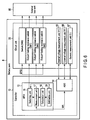
- FIG. 6 is a block diagram showing a configuration example of a battery pack 8 of an embodiment.
- the battery pack 8 includes a controller 10 and circuit unit 20. Assume that the battery pack 8 is a battery pack including a lithium-ion battery, a battery pack to be used as an engine starting battery mounted in a vehicle or the like, or a battery pack to be used as a portable battery.
- FIG. 7 is a circuit diagram showing an example of the circuit unit 20 of this embodiment connected to an external load unit 80.
- the controller 10 is implemented as, e.g., a battery management system (BMS) for controlling the circuit unit 20. Note that the controller 10 need not be installed inside the battery pack 8, and may also be provided outside the battery pack 8.
- BMS battery management system
- the controller 10 performs control for connecting the circuit unit 20 to the external load unit 80 via a switch SW0 of the circuit unit 20.
- the controller 10 includes an MPU 12 and analog-digital converter (ADC) 14.
- ADC analog-digital converter
- the MPU 12 is connected to the ADC 14 by, e.g., an SPI (Serial Peripheral Interface), and is connected to an internal voltage measurement unit 65, external voltage measurement unit 66, and current measurement unit 67 in the circuit unit 20 via the ADC 14.
- SPI Serial Peripheral Interface
- the MPU 12 acquires, via the ADC 14, information (to be referred to as "measurement information” hereinafter) indicating an internal voltage (V1), external voltage (V), and electric current (I1) respectively measured by the internal voltage measurement unit 65, external voltage measurement unit 66, and current measurement unit 67.
- measurement information information indicating an internal voltage (V1), external voltage (V), and electric current (I1) respectively measured by the internal voltage measurement unit 65, external voltage measurement unit 66, and current measurement unit 67.
- the MPU 12 is connected to the switch SW0 and output-limiting resistance switches SW1, SW2, and SW3 in the circuit unit 20 by, e.g., a GPIO (General Purpose Input/Output).
- the output-limiting resistance switches SW1, SW2, and SW3 are arranged between an internal battery 62 of the circuit unit 20 and the external load unit 80.
- Each of the output-limiting resistance switches SW1, SW2, and SW3 is used to limit an electric current to be output to the external load unit 80.
- the output-limiting resistance switches SW1, SW2, and SW3 are also switches for controlling output-limiting resistors (precharges) for implementing three different resistance values R01, R02, and R03, respectively.
- the output current value is, for example, the value of the electric current (I1).
- the output-limiting resistance switches SW1, SW2, and SW3 are respectively associated with the output-limiting resistors for implementing the three different resistance values.
- the MPU 12 Based on the measurement information, for example, the MPU 12 transmits control signals for controlling the switch SW0 and output-limiting resistance switches SW1, SW2, and SW3 to these switches.
- the MPU 12 includes a switching unit 16, measurement unit 17, calculation unit 18, and estimation unit 19.
- the switching unit 16 performs control for switching the resistance value of the output-limiting resistor to one of the three different resistance values. For example, the switching unit 16 performs control for switching the output-limiting resistance switches SW1, SW2, and SW3 associated with the three different resistance values. Also, in accordance with an instruction for switching the resistance values from the measurement unit 17 (to be described below), the switching unit 16 performs control for switching the output-limiting resistance switches SW1, SW2, and SW3. Furthermore, the switching unit 16 performs control for closing the switch SW0 in accordance with an instruction for closing the switch SW0 from the estimation unit 19 (to be described later).
- the measurement unit 17 For each of the three different resistance values switched by the switching unit 16, the measurement unit 17 performs at least control for measuring the output current value and the voltage value of the external load unit 80 contained in the measurement information. For example, to acquire the measurement information for the output-limiting resistor associated with the output-limiting resistance switches SW1, SW2, and SW3 switched by the switching unit 16, the measurement unit 17 performs control which causes the internal voltage measurement unit 65, external voltage measurement unit 66, and current measurement unit 67 to measure the measurement information via the ADC 14.
- the measurement unit 17 acquires the measurement information from the internal voltage measurement unit 65, external voltage measurement unit 66, and current measurement unit 67 via the ADC 14. In addition, when the measurement information is thus acquired, the measurement unit 17 transmits an instruction for switching the resistance values of the output-limiting resistors to the switching unit 16, in order to acquire measurement information different from the acquired measurement information.
- the calculation unit 18 calculates a voltage value E2 corresponding to an external battery 85, a resistance value R2 corresponding to an external battery resistor 84, and a resistance value R3 corresponding to a resistance load 94, which are three unknown values (to be described later), i.e., three unknowns. Note that in this embodiment, it is assumed that the load of the external load unit 80 is not known unlike in the related art. Therefore, these unknowns must be calculated.
- the calculation unit 18 calculates an output current value (to be referred to as "an estimated output current value” hereinafter) before the external load unit 80 is connected to the circuit unit 20 via the switch SW0 without any output-limiting resistor. In other words, the calculation unit 18 calculates an output current value if the switch SW0 is closed.
- the estimation unit 19 estimates the load value of the external load unit 80 or the type of external load of the external load unit 80. Determining the external load as a result of the estimation by the estimation unit 19 as described above will be referred to as "load determination" hereinafter. Also, the load value is a value such as the voltage value E2, resistance value R2, or resistance value R3 associated with the external load of the external load unit 80. Note that the external load estimation method and determination method such as load determination as described above will be described in detail later with reference to FIG. 9 .
- the estimation unit 19 also determines whether to close the switch SW0 based on the estimation result. For example, the estimation unit 19 estimates the load value of the external load unit 80 based on the voltage value E2, resistance value R2, and resistance value R3 calculated by the calculation unit 18. Then, the estimation unit 19 estimates the type of external load of the external load unit 80 in accordance with the estimated load value. After that, based on the estimated type of the external load and the calculated estimated output current value, the estimation unit 19 determines whether to connect the circuit unit 20 and external load unit 80 via the switch SW0, i.e., whether to close the switch SW0.
- the MPU 12 performs control for connecting the external load unit 80 to the circuit unit 20 via the switch SW0 without any output-limiting resistor.
- the estimation unit 19 determines that the switch SW0 can be closed. Then, the estimation unit 19 instructs the switching unit 16 to close the switch SW0.
- the circuit unit 20 includes a plurality of output-limiting resistors.
- an output-limiting resistance unit 30 includes an output-limiting resistor 34 having the resistance value R02 and the output-limiting resistance switch SW2, and an output-limiting resistor 36 having the resistance value R03 and the output-limiting resistance switch SW3, in addition to an output-limiting resistor 72 having the resistance value R01 and the output-limiting resistance switch SW1.
- the resistance values R01, R02, and R03 have a relationship R01 > R02 > R03.
- the resistance values R01, R02, and R03 are respectively about 30, 20, and 10 ⁇ .
- the resistance values R01, R02, and R03 can be changed in accordance with the value of the external battery voltage 85, external battery resistor 84, or resistor 94 in the external load unit 80 or 90.
- the output-limiting resistance switches SW1, SW2, and SW3 are respectively switches for controlling the output-limiting resistors 72, 34, and 36.
- the switch SW0 is connected in parallel to the output-limiting resistance unit 30.
- the switch SW0 is a switch for connecting the circuit unit 20 and external load unit 80 without the output-limiting resistors 72, 34, and 36. That is, the switch SW0 is equivalent to an output-limiting resistance value of 0 ⁇ .
- An internal battery unit 61 includes the internal battery 62 having a voltage value E1, and an internal battery resistor 63 connected to the internal battery 62 and having a resistance value R1. Assume that the voltage value E1 is about 10 or 20 V.
- the internal voltage measurement unit 65 measures the internal voltage (V1) as the voltage of the internal battery unit 61 with respect to ground.
- the external voltage measurement unit 66 measures the voltage of the external load unit 80 with respect to ground, i.e., the external voltage (V) as the voltage between a positive terminal 68 and negative terminal 69.
- the current measurement unit 67 is connected between the internal battery unit 61 and the output-limiting resistance unit 30 or switch SW0.
- the current measurement unit 67 measures the output current (I1) to the external load unit 80.
- the external load unit 80 includes a modeled circuit including three parameters, i.e., the external battery 85 having the voltage value E2, the external battery resistor 84 connected in series with the external battery 85 and having the resistance value R2, and a resistance load 94 connected in parallel to the external battery 85 and external battery resistor 84 and having the resistance value R3.
- the number of resistance values to be implemented by the output-limiting resistance unit 30 is set to be equal to the number of parameters. That is, when the external load unit 80 is a modeled circuit including three parameters as described above, the number of resistance values to be implemented by using, e.g., the output-limiting resistors 72, 34, and 36 is also set to three.
- the circuit configuration example shown in FIG. 7 shows the three parallel-connected fixed resistance values R01, R02, and R03 to be selectively used.
- the circuit for implementing the three resistance values is not limited to this configuration.
- FIG. 7 shows the three output-limiting resistors 72, 34, and 36, but the circuit need only include at least two output-limiting resistors. This is so because if, for example, the circuit includes the output-limiting resistors 34 and 36, the three resistance values can be implemented by the resistance value R02, the resistance value R03, and a synthetic resistance value of the resistance values R02 and R03.
- the external load unit 90 including the constant-current load unit 93 as shown in FIG. 3 can be regarded as a model like the external load unit 80 shown in FIG. 7 by handling the constant-current load unit 93 such that the battery unit voltage E2 in the battery load unit 82 shown in FIG. 7 has a minus value.
- the resistance values R01, R02, and R03 can also be changed in accordance with the value of the external battery voltage 85, external battery resistor 84, or resistor 94, i.e., the voltage value E2, resistance value R2, or resistance value R3.
- the resistance values R01, R02, and R03 can also be changed in accordance with a value assuming the load value of the external load unit 80.
- the resistance values R01, R02, and R03 can be so changed as to decrease the differences between them, within the range of resistance values by which the current value I1 is an ampere-order value (e.g., 10 A). More specifically, when the resistance values R01, R02, and R03 are 30, 20, and 10 ⁇ , the resistance values R01, R02, and R03 can be changed to 25, 20, 15 ⁇ .
- the switching unit 16 switches the output-limiting resistors 72, 34, and 36 in, e.g., descending order of resistance value. Then, based on the internal voltage (V1), external voltage (V), and output current (I1) measured in their respective connection states, the calculation unit 18 calculates the voltage value E2, resistance value R2, and resistance value R3 as the three parameters of the modeled circuit.
- the calculation unit 18 calculates the current value I1 when the switch SW0 is closed, as the estimated output current value. After that, the estimation unit 19 determines whether the calculated current value I1 is equal to or smaller than a specified value. If the calculated current value I1 is equal to or smaller than the specified value, the switching unit 16 closes the switch SW0.
- the switching unit 16 opens the switch SW0 and output-limiting resistance switches SW1, SW2, and SW3 (step S30). Then, the output-limiting resistance switch SW1 is closed with the switch SW0 and output-limiting resistance switches SW2 and SW3 being kept open (step S32).
- the internal voltage (V1), external voltage (V), and output current (I1) are measured with the output-limiting resistance switch SW1 being closed (step S32).
- the internal voltage (V1), external voltage (V), and output current (I1) obtained by this measurement are respectively regarded as an internal voltage (V1_1), external voltage (V_1), and output current (I1_1).
- the internal voltage (V1), external voltage (V), and output current (I1) are measured with the output-limiting resistance switch SW2 being closed (step S34).
- the internal voltage (V1), external voltage (V), and output current (I1) obtained by this measurement are respectively regarded as an internal voltage (V1_2), external voltage (V_2), and output current (I1_2).
- the internal voltage (V1), external voltage (V), and output current (I1) are measured with the output-limiting resistance switch SW3 being closed (step S36).
- the internal voltage (V1), external voltage (V), and output current (I1) obtained by this measurement are respectively regarded as an internal voltage (V1_3), external voltage (V_3), and output current (I1_3).
- the estimated output current value is calculated based on the internal voltages (V1_1, V1_2, and V1_3), external voltages (V_1, V_2, and V_3), and output currents (I1_1, I1_2, and I1_3) measured in steps S32, S34, and S36.
- the maximum estimated output current value (I1max_0) which is estimated when the switch SW0 is closed with the output-limiting resistance switches SW1, SW2, and SW3 being open is calculated (step S38).
- step S40 whether the calculated maximum estimated output current value (I1max_0) is smaller than a maximum allowable current value (I1max_SW0) as an eigenvalue of the switch SW0 is determined (step S40).
- step S40 If it is not determined that I1max_0 ⁇ I1max_SW0 (step S40: NO), the output-limiting resistance switch SW3 is kept closed, and the process waits for a predetermined time (e.g., 60 sec) in order to eliminate the internal-external voltage difference (V1 - V) (step S42). After the elapse of the predetermined time, the process returns to step S32.
- a predetermined time e.g. 60 sec
- step S40 YES
- the switch SW0 is closed (step S44).
- the output-limiting resistance switch SW3 is opened (step S46).
- the switch SW0 is closed with the output-limiting resistance switches SW1, SW2, and SW3 being open (step S48).
- the state of, e.g., the external load unit 80 sometimes changes.
- the external load unit 80 includes the constant-current load unit 93
- the power supply of the external load unit 80 is turned off during the elapse of the predetermined time, so the constant-current load unit 93 does not include the external load unit 80 any longer in some cases.
- the external load unit 80 includes the battery load unit 82
- the external battery 85 may be consumed.
- the resistance value as the load value of the external load unit 80 may change if one of the output-limiting resistance switches SW1, SW2, and SW3 is closed. In any of these cases, the determination condition may be satisfied in step S40 after that, and the process may advance to step S44.
- FIG. 9 is an example of a switch closing determination feasibility table 50 indicating whether the switch SW0 can be closed.
- the switch closing determination feasibility table 50 includes a switch closing determination condition item a indicating a determination condition for determining whether to close the switch SW0, and a constant-current load item b, resistance load item c, and battery load item d each indicating the type of external load which the external load unit 80 presumably includes. This table shows these items for each of the switch closing determination condition of the related art, and that of this embodiment.
- the switch closing determination condition item a corresponding to the related art, whether the absolute value of the internal-external voltage difference (V1 - V) is smaller than a predetermined potential difference ⁇ V, i.e.,
- I1max_0 ⁇ I1max_SW0 is the switch closing determination condition as indicated by the switch closing determination condition item a corresponding to this embodiment. Also, in this embodiment as described previously, it is possible to assume even a case in which the load value of the external load unit 80 or the type of external load of the external load unit 80 is unknown.
- the constant-current load item a will now be explained.
- the determination criterion of the conventional switch closing determination condition is sometimes not satisfied because the absolute value of the internal-external voltage difference (V1 - V) maintains a predetermined value (R1*I1).
- V1 - V internal-external voltage difference
- R1*I1 predetermined value
- the switch closing determination condition of this embodiment is satisfied when, for example, time elapses, even if the internal-external voltage difference (V1 - V) is produced. Therefore, even when the battery pack 60 cannot be connected to the external load unit 80 in the related art, the battery pack 60 can be connected to the external load unit 80 in this embodiment.
- the calculated voltage value E2 is a negative value (e.g., -100 V) and the calculated resistance value R2 is about 11 ⁇
- the type of external load of the external load unit 80 is the constant-current load unit 93.
- the calculated estimated output current value is a few-ten-ampere-order value
- the load value of the constant-current load 93 is also a few-ten-ampere-order value. Note that when the load value of the constant-current load 93 is on the order of a few ten amperes, this means that the current value is relatively small when assuming a case in which the battery pack 8 is a battery pack including, e.g., a lithium-ion battery. In this case, it is estimated that no large current flows even when the switch SW0 is closed, so it is possible to determine that the circuit unit 20 and external load unit 80 can be connected via the switch SW0.
- the calculated resistance value R3 is a mega-order value (e.g., 1 M ⁇ )
- the type of external load of the external load unit 80 is the resistance load unit 92.
- the calculated resistance value R3 is a mega-order value
- the load value of the estimated resistance load unit 92 is a mega-order resistance value. In this case, it is estimated that no large electric current flows even when the switch SW0 is closed because the resistance value R3 is large, so it is possible to determine that the circuit unit 20 and external load unit 80 can be connected via the switch SW0.
- the calculated voltage value E2 is 20 V and the calculated resistance value R2 is a milliohm-order value (e.g., 10 m ⁇ )
- the type of external load of the external load unit 80 is the battery load unit 82.
- the calculated resistance value R2 is a milliohm-order value
- the load value of the battery load unit 82 is also a milliohm-order resistance value.
- the external load unit 80 thus includes the battery load unit 82, the internal-external voltage difference (V1 - V) must be reduced over a long time in order to prevent heat generation caused by, e.g., the output-limiting resistors 72, 34, and 36. As will be described later, therefore, the switch SW0 cannot be closed unless the internal-external voltage difference (V1 - V) is reduced.
- the resistance load item b will be explained below with reference to FIG. 9 again.
- the determination criterion of the conventional switch closing determination condition is sometimes not satisfied because the absolute value of the internal-external voltage difference (V1 - V) maintains a predetermined value (E1 - E1(R3/(R1 + R3))). In this case, the battery pack 60 cannot be connected to the external load unit 80.
- the switch closing determination condition of this embodiment is satisfied when, for example, time elapses, even if the internal-external voltage difference (V1 - V) is produced. Therefore, even when the battery pack 60 cannot be connected to the external load unit 80 in the related art, the battery pack 60 can be connected to the external load unit 80 in this embodiment.
- the battery load item c will be explained.
- the absolute value of the internal-external voltage difference (V1 - V) decreases with the elapse of time. Accordingly, as described earlier with reference to FIG. 2 , the battery pack 60 can finally be connected to the external load unit 80 via the switch SW0 after the elapse of a few ten hours.
- the battery pack 60 can finally be connected to the external load unit 80 via the switch SW0.
- the resistance value R2 is estimated as a load value by load determination, unlike in the related art. Also, the estimated output current value is calculated. When the resistance value R2 is large, for example, a small value is calculated as the estimated output current value. As in the related art, therefore, the battery pack 60 can be connected to the external load unit 80 via the switch SW0 after the elapse of time shorter than a few ten hours.
- FIG. 10 assumes a case in which the control method of the battery pack 8 of this embodiment is applied, and the external load unit 90 includes the resistance load unit 92.
- FIG. 10 is a graph schematically showing examples of changes in internal voltage V1 and external voltage V with time when the switch SW0 is closed in this case.
- the abscissa indicates the time on the order of seconds, and the ordinate indicates the voltage (V).
- V the voltage
- the internal voltage V1 is 10 V
- the external voltage V is about 6.5 V.
- the control method of the battery pack 8 of this embodiment is applied, so the switch SW0 can be closed in ten-odd seconds (ten seconds in FIG. 10 ) on the order of seconds.
- FIG. 10 shows that the internal voltage V1 and external voltage V take a predetermined value (about 8.3 V in FIG. 10 ) after that.
- the external load unit 80 is modeled by using the three parameters, i.e., the voltage value E2, resistance value R2, and resistance value R3.
- the three output-limiting resistance units 72, 34, and 36 are switched in descending order of resistance value.
- the three parameters are calculated from equations using the internal voltage (V1), external voltage (V), and output current (I1) measured by switching like this.
- the switch SW0 can be closed if it is determined that the estimated external load is one of (1) the battery load unit 82 having a high internal resistance, (2) the resistance load unit 92 having a large resistance value, and (3) the constant-current load unit 93 having a small current value.
- the controller 10 of the battery pack 8 can estimate an external load to be connected. This makes safe reliable connection to the external load unit 80 possible within a time shorter than that in the related art.
- the switch SW0 cannot be closed in the related art because the internal-external voltage difference (V1 - V) does not disappear.
- the type of external load is estimated in at least a few ten seconds, and the switch SW0 can be closed if it is determined that the switch SW0 can safely be closed.
- the type of external load can be estimated even when, for example, the external load unit 80 includes the constant-current load unit 93. If it is determined that the switch SW0 can safely be closed, the switch SW0 can be closed in this case as well.
- the battery pack 8 can safely be connected to the external load unit 80.
- the battery pack 8 such as a lithium-ion battery can be used in various applications.
- the embodiment of the present invention provides a battery pack and control method for safely connecting an external load.
Landscapes
- Engineering & Computer Science (AREA)
- Power Engineering (AREA)
- Secondary Cells (AREA)
- Emergency Protection Circuit Devices (AREA)
- Direct Current Feeding And Distribution (AREA)
- Charge And Discharge Circuits For Batteries Or The Like (AREA)
Abstract
Description
- Embodiments described herein relate generally to a battery pack and control method for connecting an external load.
- Conventionally, a high-output battery pack includes a switch between an internal battery and external load for safety's sake, and a main circuit is disconnected from the external load by opening the switch when the battery pack is not in use.
- When using the battery pack, the internal battery of the battery pack can be connected to the external load by closing the switch. However, if a voltage difference (to be referred to as "an internal-external voltage difference" hereinafter) between the internal battery and external load is large, a large electric current flows when they are connected, so a component of the switch or the like is sometimes broken.
- Accordingly, the following method is known as an example of a control method of suppressing this large electric current when connecting the battery and load. That is, this method measures the internal-external voltage difference, and, if the measured internal-external voltage difference is larger than a predetermined value, connects the external load via an output-limiting resistance for limiting an electric current to be output to the external load. The control method closes the switch if the internal-external voltage difference becomes smaller than the predetermined value.
- This conventional control method will briefly be explained with reference to
FIG. 1. FIG. 1 shows a circuit example of aconventional battery pack 60 and anexternal load unit 80 connected to thebattery pack 60. Note that in addition to the circuit as shown inFIG. 1 , thebattery pack 60 includes a controller (not shown) for controlling elements forming the circuit. - The
battery pack 60 is a battery pack such as a lithium-ion battery. Thebattery pack 60 includes aninternal battery unit 61, switch SW0, internalvoltage measurement unit 65, externalvoltage measurement unit 66,current measurement unit 67,positive terminal 68,negative terminal 69, and output-limitingresistance unit 70. - Also, the
internal battery unit 61 includes aninternal battery 62 and internal battery resistance 63. The output-limitingresistance unit 70 includes an output-limitingresistor 72 having a resistance value R01, and an output-limiting resistance switch SW1. - On the other hand, the
external load unit 80 to be connected to thebattery pack 60 includes abattery load unit 82 and resistance/coil/capacitance load unit 83. Thebattery load unit 82 includes anexternal battery 85 andexternal battery resistor 84. The resistance/coil/capacitance load unit 83 includes a resistance/coil/capacitance load 86 which is one of a resistance load, coil load, and capacitance load. For example, the coil load is that of a starter installed in a vehicle. - In this arrangement, the
external load unit 80 includes thebattery load unit 82, and this produces a voltage difference (V1 - V) (to be referred to as "an internal-external voltage difference" hereinafter) between an internal voltage V1 measured by the internalvoltage measurement unit 65 of thebattery load unit 82, and an external voltage V measured by the externalvoltage measurement unit 66. - This internal-external voltage difference disappears with the elapse of time as shown in
FIG. 2. FIG. 2 is an example of a graph schematically showing changes in internal voltage V1 and external voltage V with time, when the output-limiting resistance switch SW1 is closed with thebattery load unit 82 being included in theexternal load unit 80. - Initially, the internal voltage V1 is 12 V, and the external voltage V is 8 V, so there is an internal-external voltage difference. Then, the internal-external voltage difference gradually decreases because an electric current I1 measured by the
current measurement unit 67 flows through the output-limitingresistance unit 70. When a few ten hours (e.g., ten hours) elapse, the internal-external voltage difference disappears, and thebattery pack 60 andexternal load unit 80 are completely connected by closing the switch SW0. - Unfortunately, even when using the conventional control method as described above, a large electric current may flow when the
battery pack 60 is connected to theexternal load unit 80 if the internal-external voltage difference is large. - Also, when the external load is a battery load, coil load, or capacitance load, the internal-external voltage difference can be eliminated through the output-limiting resistor as described above. However, when an
external load unit 90 includes aresistance load unit 92 or constant-current load unit 93 as shown inFIG. 3 , the internal-external voltage difference keeps taking a predetermined value as shown inFIGS. 4 and 5 . Accordingly, the internal-external voltage difference does not disappear but takes the predetermined value, so the switch SW0 cannot be closed even after the elapse of time. - Assume that, as shown in
FIG. 3 , theexternal load unit 90 includes theresistance load unit 92 including aresistor 94 and a constant-current load 93 including a constant-current source 95. Assume also a conventional control method using only the internal-external voltage difference as a closing determination condition for determining whether to close the switch SW0. In this case, even when the switch SW0 can safely be closed, it is determined that the switch SW0 cannot be closed because the internal-external voltage difference keeps taking the predetermined value. -
FIG. 4 is an example of a graph schematically showing changes in internal voltage V1 and external voltage V with time, when theexternal load unit 90 includes theresistance load unit 92, and the output-limiting resistance switch SW1 is closed. - As shown in
FIG. 4 , the internal voltage V1 is 10 V, the external voltage V is about 6.5 V, and the internal voltage V1 and external voltage V keep taking the predetermined values even when time elapses. Since the internal-external voltage difference does not disappear, therefore, the switch SW0 cannot be closed, so the resistance load cannot be connected. - Likewise,
FIG. 5 is an example of a graph schematically showing changes in internal voltage V1 and external voltage V with time, when theexternal load unit 90 includes the constant-current load unit 93, and the output-limiting resistance switch SW1 is closed. - As shown in
FIG. 5 , the internal voltage V1 is 10 V, the external voltage V is about 9.5 V, and the internal voltage V1 and external voltage V keep taking the predetermined values even when time elapses. Since the internal-external voltage difference does not disappear, therefore, the switch SW0 cannot be closed, so the constant-current load cannot be connected. - From the foregoing, it is desirable to provide a battery pack and control method for safely and reliably connecting an external load.
-
-
FIG. 1 is a circuit diagram showing an example of a circuit unit of a conventional battery pack and an external load unit; -
FIG. 2 is a graph schematically showing examples of changes in internal voltage and external voltage with time, when a battery control method performed by the conventional battery pack is applied, and the external load unit includes a battery load unit; -
FIG. 3 is a circuit diagram showing another example of the circuit unit of the conventional battery pack and the external load unit; -
FIG. 4 is a graph schematically showing examples of changes in internal voltage and external voltage with time, when the battery control method performed by the conventional battery pack is applied, and the external load unit includes a resistance load unit; -
FIG. 5 is a graph schematically showing examples of changes in internal voltage and external voltage with time, when the battery control method performed by the conventional battery pack is applied, and the external load unit includes a constant-current load unit; -
FIG. 6 is a block diagram showing a configuration example of a battery pack of an embodiment; -
FIG. 7 is a circuit diagram showing an example of a circuit unit of the battery pack of the embodiment and an external load unit; -
FIG. 8 is a flowchart showing an example of a battery control procedure performed by the battery pack of the embodiment; -
FIG. 9 shows a switch closing determination feasibility table showing whether to close a switch SW0, when a battery control method performed by the battery pack of the embodiment is applied; and -
FIG. 10 is a graph schematically showing examples of changes in internal voltage and external voltage with time, when the battery control method performed by the battery pack of the embodiment is applied, and the external load unit includes a resistance load unit. - In general, according to one embodiment, a battery pack for connecting an external load via a switch includes an output-limiting resistor, a switching module, a measurement module, and a control module. The output-limiting resistor is arranged between an internal battery of the battery pack and the external load. The output-limiting resistor is used to limit an output current value to be output to the external load. And the output-limiting resistor is configured to implement three different resistance values of a first resistance value, a second resistance value, and a third resistance value. The switching module is configured to switch a resistance value of the output-limiting resistor to one of the first resistance value, the second resistance value, and the third resistance value. The measurement module is configured to measure the output current value and a voltage value of the external load, for each of the first resistance value, the second resistance value, and the third resistance value. And the control module is configured to perform, in accordance with an external load estimated based on the measurement result, control for connecting the external load to the battery pack via the switch (SW0) without the output-limiting resistor.
- Various embodiments will be described hereinafter with reference to the accompanying drawings.
-
FIG. 6 is a block diagram showing a configuration example of abattery pack 8 of an embodiment. Thebattery pack 8 includes acontroller 10 andcircuit unit 20. Assume that thebattery pack 8 is a battery pack including a lithium-ion battery, a battery pack to be used as an engine starting battery mounted in a vehicle or the like, or a battery pack to be used as a portable battery. -
FIG. 7 is a circuit diagram showing an example of thecircuit unit 20 of this embodiment connected to anexternal load unit 80. - The
controller 10 is implemented as, e.g., a battery management system (BMS) for controlling thecircuit unit 20. Note that thecontroller 10 need not be installed inside thebattery pack 8, and may also be provided outside thebattery pack 8. - The
controller 10 performs control for connecting thecircuit unit 20 to theexternal load unit 80 via a switch SW0 of thecircuit unit 20. To implement this control, thecontroller 10 includes anMPU 12 and analog-digital converter (ADC) 14. - The
MPU 12 is connected to theADC 14 by, e.g., an SPI (Serial Peripheral Interface), and is connected to an internalvoltage measurement unit 65, externalvoltage measurement unit 66, andcurrent measurement unit 67 in thecircuit unit 20 via theADC 14. - Also, the
MPU 12 acquires, via theADC 14, information (to be referred to as "measurement information" hereinafter) indicating an internal voltage (V1), external voltage (V), and electric current (I1) respectively measured by the internalvoltage measurement unit 65, externalvoltage measurement unit 66, andcurrent measurement unit 67. - Furthermore, the
MPU 12 is connected to the switch SW0 and output-limiting resistance switches SW1, SW2, and SW3 in thecircuit unit 20 by, e.g., a GPIO (General Purpose Input/Output). Note that as shown in the circuit diagram ofFIG. 7 , the output-limiting resistance switches SW1, SW2, and SW3 are arranged between aninternal battery 62 of thecircuit unit 20 and theexternal load unit 80. Each of the output-limiting resistance switches SW1, SW2, and SW3 is used to limit an electric current to be output to theexternal load unit 80. The output-limiting resistance switches SW1, SW2, and SW3 are also switches for controlling output-limiting resistors (precharges) for implementing three different resistance values R01, R02, and R03, respectively. Note that the output current value is, for example, the value of the electric current (I1). Note also that the output-limiting resistance switches SW1, SW2, and SW3 are respectively associated with the output-limiting resistors for implementing the three different resistance values. - Based on the measurement information, for example, the
MPU 12 transmits control signals for controlling the switch SW0 and output-limiting resistance switches SW1, SW2, and SW3 to these switches. To implement this, theMPU 12 includes aswitching unit 16,measurement unit 17,calculation unit 18, andestimation unit 19. - The switching
unit 16 performs control for switching the resistance value of the output-limiting resistor to one of the three different resistance values. For example, the switchingunit 16 performs control for switching the output-limiting resistance switches SW1, SW2, and SW3 associated with the three different resistance values. Also, in accordance with an instruction for switching the resistance values from the measurement unit 17 (to be described below), the switchingunit 16 performs control for switching the output-limiting resistance switches SW1, SW2, and SW3. Furthermore, the switchingunit 16 performs control for closing the switch SW0 in accordance with an instruction for closing the switch SW0 from the estimation unit 19 (to be described later). - For each of the three different resistance values switched by the switching
unit 16, themeasurement unit 17 performs at least control for measuring the output current value and the voltage value of theexternal load unit 80 contained in the measurement information. For example, to acquire the measurement information for the output-limiting resistor associated with the output-limiting resistance switches SW1, SW2, and SW3 switched by the switchingunit 16, themeasurement unit 17 performs control which causes the internalvoltage measurement unit 65, externalvoltage measurement unit 66, andcurrent measurement unit 67 to measure the measurement information via theADC 14. - Then, the
measurement unit 17 acquires the measurement information from the internalvoltage measurement unit 65, externalvoltage measurement unit 66, andcurrent measurement unit 67 via theADC 14. In addition, when the measurement information is thus acquired, themeasurement unit 17 transmits an instruction for switching the resistance values of the output-limiting resistors to theswitching unit 16, in order to acquire measurement information different from the acquired measurement information. - Based on the measurement information acquired by the
measurement unit 17, thecalculation unit 18 calculates a voltage value E2 corresponding to anexternal battery 85, a resistance value R2 corresponding to anexternal battery resistor 84, and a resistance value R3 corresponding to aresistance load 94, which are three unknown values (to be described later), i.e., three unknowns. Note that in this embodiment, it is assumed that the load of theexternal load unit 80 is not known unlike in the related art. Therefore, these unknowns must be calculated. - Also, based on the measurement information, the
calculation unit 18 calculates an output current value (to be referred to as "an estimated output current value" hereinafter) before theexternal load unit 80 is connected to thecircuit unit 20 via the switch SW0 without any output-limiting resistor. In other words, thecalculation unit 18 calculates an output current value if the switch SW0 is closed. - Based on the voltage value E2, resistance value R2, and resistance value R3 calculated by the
calculation unit 18, theestimation unit 19 estimates the load value of theexternal load unit 80 or the type of external load of theexternal load unit 80. Determining the external load as a result of the estimation by theestimation unit 19 as described above will be referred to as "load determination" hereinafter. Also, the load value is a value such as the voltage value E2, resistance value R2, or resistance value R3 associated with the external load of theexternal load unit 80. Note that the external load estimation method and determination method such as load determination as described above will be described in detail later with reference toFIG. 9 . - The
estimation unit 19 also determines whether to close the switch SW0 based on the estimation result. For example, theestimation unit 19 estimates the load value of theexternal load unit 80 based on the voltage value E2, resistance value R2, and resistance value R3 calculated by thecalculation unit 18. Then, theestimation unit 19 estimates the type of external load of theexternal load unit 80 in accordance with the estimated load value. After that, based on the estimated type of the external load and the calculated estimated output current value, theestimation unit 19 determines whether to connect thecircuit unit 20 andexternal load unit 80 via the switch SW0, i.e., whether to close the switch SW0. - In accordance with, e.g., the estimated load value, estimated external load type, or estimated output current value, the
MPU 12 performs control for connecting theexternal load unit 80 to thecircuit unit 20 via the switch SW0 without any output-limiting resistor. - For example, when the estimated output current value is smaller than an allowable current value of the
circuit unit 20, theestimation unit 19 determines that the switch SW0 can be closed. Then, theestimation unit 19 instructs the switchingunit 16 to close the switch SW0. - Next, examples of the circuit configurations of the
circuit unit 20 andexternal load unit 80 will be explained with reference toFIG. 7 . Note that an explanation of the same arrangements or contents as those shownFIG. 1 or3 will be omitted. - Unlike the
battery pack 60 of the related art as shown inFIGS. 1 and3 , thecircuit unit 20 includes a plurality of output-limiting resistors. For example, an output-limitingresistance unit 30 includes an output-limitingresistor 34 having the resistance value R02 and the output-limiting resistance switch SW2, and an output-limitingresistor 36 having the resistance value R03 and the output-limiting resistance switch SW3, in addition to an output-limitingresistor 72 having the resistance value R01 and the output-limiting resistance switch SW1. The resistance values R01, R02, and R03 have a relationship R01 > R02 > R03. For example, the resistance values R01, R02, and R03 are respectively about 30, 20, and 10 Ω. However, the resistance values R01, R02, and R03 can be changed in accordance with the value of theexternal battery voltage 85,external battery resistor 84, orresistor 94 in theexternal load unit - The output-limiting resistance switches SW1, SW2, and SW3 are respectively switches for controlling the output-limiting
resistors - The switch SW0 is connected in parallel to the output-limiting
resistance unit 30. The switch SW0 is a switch for connecting thecircuit unit 20 andexternal load unit 80 without the output-limitingresistors - An
internal battery unit 61 includes theinternal battery 62 having a voltage value E1, and an internal battery resistor 63 connected to theinternal battery 62 and having a resistance value R1. Assume that the voltage value E1 is about 10 or 20 V. - The internal
voltage measurement unit 65 measures the internal voltage (V1) as the voltage of theinternal battery unit 61 with respect to ground. - The external
voltage measurement unit 66 measures the voltage of theexternal load unit 80 with respect to ground, i.e., the external voltage (V) as the voltage between apositive terminal 68 andnegative terminal 69. - The
current measurement unit 67 is connected between theinternal battery unit 61 and the output-limitingresistance unit 30 or switch SW0. Thecurrent measurement unit 67 measures the output current (I1) to theexternal load unit 80. - On the other hand, the
external load unit 80 includes a modeled circuit including three parameters, i.e., theexternal battery 85 having the voltage value E2, theexternal battery resistor 84 connected in series with theexternal battery 85 and having the resistance value R2, and aresistance load 94 connected in parallel to theexternal battery 85 andexternal battery resistor 84 and having the resistance value R3. - The number of resistance values to be implemented by the output-limiting
resistance unit 30 is set to be equal to the number of parameters. That is, when theexternal load unit 80 is a modeled circuit including three parameters as described above, the number of resistance values to be implemented by using, e.g., the output-limitingresistors - To implement the three resistance values, the circuit configuration example shown in
FIG. 7 shows the three parallel-connected fixed resistance values R01, R02, and R03 to be selectively used. However, the circuit for implementing the three resistance values is not limited to this configuration. - For example,
FIG. 7 shows the three output-limitingresistors resistors - It is also possible to implement the three resistance values by using one variable resistor and properly changing its resistance value.
- Also, even the
external load unit 90 including the constant-current load unit 93 as shown inFIG. 3 can be regarded as a model like theexternal load unit 80 shown inFIG. 7 by handling the constant-current load unit 93 such that the battery unit voltage E2 in thebattery load unit 82 shown inFIG. 7 has a minus value. - Note that as described previously, the resistance values R01, R02, and R03 can also be changed in accordance with the value of the
external battery voltage 85,external battery resistor 84, orresistor 94, i.e., the voltage value E2, resistance value R2, or resistance value R3. In other words, the resistance values R01, R02, and R03 can also be changed in accordance with a value assuming the load value of theexternal load unit 80. - Assume a case in which it is already known that the resistance value R2 or R3 is a milliohm-order value. In this case, the resistance values R01, R02, and R03 can be so changed as to decrease the differences between them, within the range of resistance values by which the current value I1 is an ampere-order value (e.g., 10 A). More specifically, when the resistance values R01, R02, and R03 are 30, 20, and 10 Ω, the resistance values R01, R02, and R03 can be changed to 25, 20, 15 Ω.
- Next, the procedure of a battery control method using the
battery pack 8 will be explained with reference toFIG. 8 . - First, an outline of the battery control method of this embodiment will be explained. The switching
unit 16 switches the output-limitingresistors calculation unit 18 calculates the voltage value E2, resistance value R2, and resistance value R3 as the three parameters of the modeled circuit. - Subsequently, the
calculation unit 18 calculates the current value I1 when the switch SW0 is closed, as the estimated output current value. After that, theestimation unit 19 determines whether the calculated current value I1 is equal to or smaller than a specified value. If the calculated current value I1 is equal to or smaller than the specified value, the switchingunit 16 closes the switch SW0. - Details of the procedure of the battery control method will now be explained below.
- First, the switching
unit 16 opens the switch SW0 and output-limiting resistance switches SW1, SW2, and SW3 (step S30). Then, the output-limiting resistance switch SW1 is closed with the switch SW0 and output-limiting resistance switches SW2 and SW3 being kept open (step S32). - Subsequently, the internal voltage (V1), external voltage (V), and output current (I1) are measured with the output-limiting resistance switch SW1 being closed (step S32). The internal voltage (V1), external voltage (V), and output current (I1) obtained by this measurement are respectively regarded as an internal voltage (V1_1), external voltage (V_1), and output current (I1_1).
- Similarly, the output-limiting resistance switch SW2 is closed with the switch SW0 and output-limiting resistance switches SW1 and SW3 being kept open (step S34).
- Then, the internal voltage (V1), external voltage (V), and output current (I1) are measured with the output-limiting resistance switch SW2 being closed (step S34). The internal voltage (V1), external voltage (V), and output current (I1) obtained by this measurement are respectively regarded as an internal voltage (V1_2), external voltage (V_2), and output current (I1_2).
- Likewise, the output-limiting resistance switch SW3 is closed with the switch SW0 and output-limiting resistance switches SW1 and SW2 being kept open (step S36).
- Then, the internal voltage (V1), external voltage (V), and output current (I1) are measured with the output-limiting resistance switch SW3 being closed (step S36). The internal voltage (V1), external voltage (V), and output current (I1) obtained by this measurement are respectively regarded as an internal voltage (V1_3), external voltage (V_3), and output current (I1_3).
- Subsequently, the estimated output current value is calculated based on the internal voltages (V1_1, V1_2, and V1_3), external voltages (V_1, V_2, and V_3), and output currents (I1_1, I1_2, and I1_3) measured in steps S32, S34, and S36.
- A practical estimated output current value calculating method will be explained below.
- An equation I1 = (V - E2)/R2 + V/R3 holds between the internal voltages (V1_1, V1_2, and V1_3), external voltages (V_1, V_2, and V_3), and output currents (I1_1, I1_2, and I1_3), and the voltage value E2, resistance value R2, and resistance value R3 as unknowns. Therefore, three simultaneous equations I1_1 = (V_1 - E2)/R2 + V/R3, I1_2 = (V_2 - E2)/R2 + V/R3, and I1_3 = (V_3 - E2)/R2 + V/R3 hold. Accordingly, the voltage value E2, resistance value R2, and resistance value R3 are calculated by solving these three simultaneous equations.
- In addition, an equation (E1 - V)/R1 = (V - E2)/R2 + V/R3 also holds. By substituting the calculated voltage value E2, resistance value R2, and resistance value R3 into this equation, the external voltage V (V_0) when the switch SW0 is closed is calculated. Then, a maximum estimated output current (I1max_0) when the switch SW0 is closed is calculated from an equation I1max_0 = (V_0 - E2)/R2 + V_0/R3.
- Thus, the maximum estimated output current value (I1max_0) which is estimated when the switch SW0 is closed with the output-limiting resistance switches SW1, SW2, and SW3 being open is calculated (step S38).
- Then, whether the calculated maximum estimated output current value (I1max_0) is smaller than a maximum allowable current value (I1max_SW0) as an eigenvalue of the switch SW0 is determined (step S40).
- If it is not determined that I1max_0 < I1max_SW0 (step S40: NO), the output-limiting resistance switch SW3 is kept closed, and the process waits for a predetermined time (e.g., 60 sec) in order to eliminate the internal-external voltage difference (V1 - V) (step S42). After the elapse of the predetermined time, the process returns to step S32.
- On the other hand, if it is determined that I1max_0 < I1max_SW0 (step S40: YES), i.e., if it is determined that the
external load unit 80 can be connected to thecircuit unit 20 via the switch SW0, the switch SW0 is closed (step S44). Then, the output-limiting resistance switch SW3 is opened (step S46). Thus, the switch SW0 is closed with the output-limiting resistance switches SW1, SW2, and SW3 being open (step S48). - Note that when the process waits for the predetermined time in step S42, the state of, e.g., the
external load unit 80 sometimes changes. For example, when theexternal load unit 80 includes the constant-current load unit 93, the power supply of theexternal load unit 80 is turned off during the elapse of the predetermined time, so the constant-current load unit 93 does not include theexternal load unit 80 any longer in some cases. As another example, when theexternal load unit 80 includes thebattery load unit 82, theexternal battery 85 may be consumed. As still another example, when theexternal load unit 80 includes, e.g., a fuse which changes its resistance value due to heat generation, the resistance value as the load value of theexternal load unit 80 may change if one of the output-limiting resistance switches SW1, SW2, and SW3 is closed. In any of these cases, the determination condition may be satisfied in step S40 after that, and the process may advance to step S44. - The determination result indicating whether the switch SW0 can be closed will be explained below with reference to
FIG. 9. FIG. 9 is an example of a switch closing determination feasibility table 50 indicating whether the switch SW0 can be closed. - The switch closing determination feasibility table 50 includes a switch closing determination condition item a indicating a determination condition for determining whether to close the switch SW0, and a constant-current load item b, resistance load item c, and battery load item d each indicating the type of external load which the
external load unit 80 presumably includes. This table shows these items for each of the switch closing determination condition of the related art, and that of this embodiment. - In the related art, as indicated by the switch closing determination condition item a corresponding to the related art, whether the absolute value of the internal-external voltage difference (V1 - V) is smaller than a predetermined potential difference ΔV, i.e., |V1 - V| < ΔV is the switch closing determination condition. Also, in the related art as described previously, it is possible to assume only a case in which the load value of the
external load unit 80 or the type of external load of theexternal load unit 80 is already known. - On the other hand, in this embodiment, I1max_0 < I1max_SW0 is the switch closing determination condition as indicated by the switch closing determination condition item a corresponding to this embodiment. Also, in this embodiment as described previously, it is possible to assume even a case in which the load value of the
external load unit 80 or the type of external load of theexternal load unit 80 is unknown. - The constant-current load item a will now be explained. In the related art, the determination criterion of the conventional switch closing determination condition is sometimes not satisfied because the absolute value of the internal-external voltage difference (V1 - V) maintains a predetermined value (R1*I1). In a case like this, the
battery pack 60 cannot be connected to theexternal load unit 80. - On the other hand, in this embodiment, when it is determined by load determination that the
external load unit 80 includes the constant-current load unit 93, the switch closing determination condition of this embodiment is satisfied when, for example, time elapses, even if the internal-external voltage difference (V1 - V) is produced. Therefore, even when thebattery pack 60 cannot be connected to theexternal load unit 80 in the related art, thebattery pack 60 can be connected to theexternal load unit 80 in this embodiment. - Details of the external load estimation method and determination method such as load determination will be explained below.
- For example, when the calculated voltage value E2 is a negative value (e.g., -100 V) and the calculated resistance value R2 is about 11 Ω, it is possible to estimate that the type of external load of the
external load unit 80 is the constant-current load unit 93. Also, when the calculated estimated output current value is a few-ten-ampere-order value, it is possible to estimate that the load value of the constant-current load 93 is also a few-ten-ampere-order value. Note that when the load value of the constant-current load 93 is on the order of a few ten amperes, this means that the current value is relatively small when assuming a case in which thebattery pack 8 is a battery pack including, e.g., a lithium-ion battery. In this case, it is estimated that no large current flows even when the switch SW0 is closed, so it is possible to determine that thecircuit unit 20 andexternal load unit 80 can be connected via the switch SW0. - Also, when the calculated resistance value R3 is a mega-order value (e.g., 1 MΩ), it is possible to estimate that the type of external load of the
external load unit 80 is theresistance load unit 92. In addition, since the calculated resistance value R3 is a mega-order value, it is estimated that the load value of the estimatedresistance load unit 92 is a mega-order resistance value. In this case, it is estimated that no large electric current flows even when the switch SW0 is closed because the resistance value R3 is large, so it is possible to determine that thecircuit unit 20 andexternal load unit 80 can be connected via the switch SW0. - Furthermore, when, for example, the calculated voltage value E2 is 20 V and the calculated resistance value R2 is a milliohm-order value (e.g., 10 mΩ), it is possible to estimate that the type of external load of the
external load unit 80 is thebattery load unit 82. Since the calculated resistance value R2 is a milliohm-order value, it is possible to estimate that the load value of thebattery load unit 82 is also a milliohm-order resistance value. Note that when theexternal load unit 80 thus includes thebattery load unit 82, the internal-external voltage difference (V1 - V) must be reduced over a long time in order to prevent heat generation caused by, e.g., the output-limitingresistors - The resistance load item b will be explained below with reference to
FIG. 9 again. - In the related art, the determination criterion of the conventional switch closing determination condition is sometimes not satisfied because the absolute value of the internal-external voltage difference (V1 - V) maintains a predetermined value (E1 - E1(R3/(R1 + R3))). In this case, the
battery pack 60 cannot be connected to theexternal load unit 80. - On the other hand, in this embodiment, when it is determined by load determination that the
external load unit 80 includes theresistance load unit 92, the switch closing determination condition of this embodiment is satisfied when, for example, time elapses, even if the internal-external voltage difference (V1 - V) is produced. Therefore, even when thebattery pack 60 cannot be connected to theexternal load unit 80 in the related art, thebattery pack 60 can be connected to theexternal load unit 80 in this embodiment. - Next, the battery load item c will be explained. In the related art, the absolute value of the internal-external voltage difference (V1 - V) decreases with the elapse of time. Accordingly, as described earlier with reference to
FIG. 2 , thebattery pack 60 can finally be connected to theexternal load unit 80 via the switch SW0 after the elapse of a few ten hours. - On the other hand, in this embodiment, when it is determined by load determination that the
external load unit 80 includes thebattery load unit 82, the absolute value of the internal-external voltage difference (V1 - V) decreases with the elapse of time. Therefore, thebattery pack 60 can finally be connected to theexternal load unit 80 via the switch SW0. - Furthermore, in this embodiment, the resistance value R2 is estimated as a load value by load determination, unlike in the related art. Also, the estimated output current value is calculated. When the resistance value R2 is large, for example, a small value is calculated as the estimated output current value. As in the related art, therefore, the
battery pack 60 can be connected to theexternal load unit 80 via the switch SW0 after the elapse of time shorter than a few ten hours. -
FIG. 10 assumes a case in which the control method of thebattery pack 8 of this embodiment is applied, and theexternal load unit 90 includes theresistance load unit 92.FIG. 10 is a graph schematically showing examples of changes in internal voltage V1 and external voltage V with time when the switch SW0 is closed in this case. - Referring to
FIG. 10 , the abscissa indicates the time on the order of seconds, and the ordinate indicates the voltage (V). Initially, the internal voltage V1 is 10 V, and the external voltage V is about 6.5 V. After that, the control method of thebattery pack 8 of this embodiment is applied, so the switch SW0 can be closed in ten-odd seconds (ten seconds inFIG. 10 ) on the order of seconds.FIG. 10 shows that the internal voltage V1 and external voltage V take a predetermined value (about 8.3 V inFIG. 10 ) after that. - This embodiment as described above can achieve the following effects.
- The
external load unit 80 is modeled by using the three parameters, i.e., the voltage value E2, resistance value R2, and resistance value R3. In accordance with this modeling, the three output-limitingresistance units battery pack 8 to theexternal load unit 80. More specifically, it is possible to estimate the type of external load of theexternal load unit 80, and the estimated output current value as an output current value when the switch SW0 is closed. Therefore, even when the internal-external voltage difference (V1 - V) is large, for example, the switch SW0 can be closed if it is determined that the estimated external load is one of (1) thebattery load unit 82 having a high internal resistance, (2) theresistance load unit 92 having a large resistance value, and (3) the constant-current load unit 93 having a small current value. - Also, the
controller 10 of thebattery pack 8 can estimate an external load to be connected. This makes safe reliable connection to theexternal load unit 80 possible within a time shorter than that in the related art. - More specifically, even when the
external load unit 80 includes theresistance load unit 92 and the switch SW0 can safely be closed, the switch SW0 cannot be closed in the related art because the internal-external voltage difference (V1 - V) does not disappear. In this embodiment, however, the type of external load is estimated in at least a few ten seconds, and the switch SW0 can be closed if it is determined that the switch SW0 can safely be closed. - In addition, since the
external load unit 80 is modeled by using the three parameters as described above, the type of external load can be estimated even when, for example, theexternal load unit 80 includes the constant-current load unit 93. If it is determined that the switch SW0 can safely be closed, the switch SW0 can be closed in this case as well. - Furthermore, even when the type of external load is unknown, the
battery pack 8 can safely be connected to theexternal load unit 80. In other words, thebattery pack 8 such as a lithium-ion battery can be used in various applications. - As described above, the embodiment of the present invention provides a battery pack and control method for safely connecting an external load.
- While certain embodiments have been described, these embodiments have been presented by way of example only, and are not intended to limit the scope of the inventions. Indeed, the novel embodiments described herein may be embodied in a variety of other forms; furthermore, various omissions, substitutions and changes in the form of the embodiments described herein may be made without departing from the spirit of the inventions. The accompanying claims and their equivalents are intended to cover such forms or modifications as would fall within the scope and spirit of the inventions.
Claims (7)
- A battery pack for connecting an external load via a switch, characterized by comprising:an output-limiting resistor (72, 34, 36) arranged between an internal battery of the battery pack (8) and the external load (80), wherein the output-limiting resistor (72, 34, 36) is used to limit an output current value to be output to the external load, and wherein the output-limiting resistor (72, 34, 36) is configured to implement three different resistance values (R01, R02, R03) of a first resistance value, a second resistance value, and a third resistance value;a switching module (16) configured to switch a resistance value of the output-limiting resistor to one of the first resistance value, the second resistance value, and the third resistance value;a measurement module (17) configured to measure the output current value and a voltage value of the external load, for each of the first resistance value, the second resistance value, and the third resistance value; anda control module (10) configured to perform, in accordance with an external load estimated based on the measurement result, control for connecting the external load to the battery pack via the switch (SW0) without the output-limiting resistor.
- The battery pack of claim 1, characterized in that
the first resistance value is larger than the second resistance value, and the second resistance value is larger than the third resistance value, and
the switching module performs switching in an order of the first resistance value, the second resistance value, and the third resistance value. - The battery pack of claim 1 or 2, characterized in that
the external load includes a modeled circuit including three parameters of an external battery (84), an external battery resistor (85) connected in series with the external battery, and a resistance load (94) connected in parallel to the external battery and the external battery resistor, and
the number of parameters is equal to the number of resistance values implemented by the output-limiting resistor. - The battery pack of claim 1, 2, or 3, characterized in that the control module calculates the output current value before the external load is connected to the battery pack via the switch without the output-limiting resistor, and connects the external load to the battery pack if the calculated output current value is smaller than an allowable current value of the battery pack.
- The battery pack of claim 1, 2, 3, or 4, characterized in that the external load includes at least one of a battery load (82), a resistance load (92), and a constant-current load (93).
- The battery pack of claim 1, 2, 3, 4, or 5, characterized in that the output-limiting resistor includes at least two parallel-connected fixed resistors or a variable resistor.
- A control method for a battery pack for connecting an external load via a switch, characterized by comprising:switching a resistance value of an output-limiting resistor arranged between an internal battery of the battery pack and the external load to one of the first resistance value, the second resistance value, and the third resistance value, wherein the output-limiting resistor is used to limit an output current value to be output to the external load, and wherein the output-limiting resistor is configured to implement three different resistance values of a first resistance value, a second resistance value, and a third resistance value;measuring the output current value and a voltage value of the external load, for each of the first resistance value, the second resistance value, and the third resistance value; andperforming, in accordance with an external load estimated based on the measurement result, control for connecting the external load to the battery pack via the switch without the output-limiting resistor.
Applications Claiming Priority (1)
| Application Number | Priority Date | Filing Date | Title |
|---|---|---|---|
| JP2015130661A JP6174084B2 (en) | 2015-06-30 | 2015-06-30 | Battery pack and control method thereof |
Publications (1)
| Publication Number | Publication Date |
|---|---|
| EP3113317A1 true EP3113317A1 (en) | 2017-01-04 |
Family
ID=55272241
Family Applications (1)
| Application Number | Title | Priority Date | Filing Date |
|---|---|---|---|
| EP16152708.0A Withdrawn EP3113317A1 (en) | 2015-06-30 | 2016-01-26 | Battery pack and control method |
Country Status (4)
| Country | Link |
|---|---|
| US (1) | US9887572B2 (en) |
| EP (1) | EP3113317A1 (en) |
| JP (1) | JP6174084B2 (en) |
| AU (1) | AU2016200422B2 (en) |
Cited By (1)
| Publication number | Priority date | Publication date | Assignee | Title |
|---|---|---|---|---|
| EP3376567A1 (en) * | 2017-03-14 | 2018-09-19 | Kabushiki Kaisha Toshiba | Battery pack and control method |
Families Citing this family (3)
| Publication number | Priority date | Publication date | Assignee | Title |
|---|---|---|---|---|
| FR3073990A1 (en) * | 2017-11-17 | 2019-05-24 | Smartbatz | ELECTRONIC DEVICE FOR LOADING A PLURALITY OF EXTERNAL BATTERIES FOR MOBILE TERMINAL, ELECTRONIC ASSEMBLY COMPRISING A PLURALITY OF EXTERNAL BATTERIES AND A SUCH CHARGING DEVICE |
| DE102019112706A1 (en) * | 2019-05-15 | 2020-11-19 | Bayerische Motoren Werke Aktiengesellschaft | Method and device for supplying energy to an electrical consumer of a vehicle |
| WO2022191233A1 (en) * | 2021-03-10 | 2022-09-15 | 本田技研工業株式会社 | Electric power device, and control method for same |
Citations (3)
| Publication number | Priority date | Publication date | Assignee | Title |
|---|---|---|---|---|
| EP1263110A2 (en) * | 2001-05-28 | 2002-12-04 | Matsushita Electric Industrial Co., Ltd. | Battery pack system |
| US20110234168A1 (en) * | 2010-03-29 | 2011-09-29 | Tae-Heom Park | Battery pack and method of controlling the battery pack |
| US20150061376A1 (en) * | 2013-08-30 | 2015-03-05 | Ford Global Technologies, Llc | Pre-Charge Quick Key Cycling Protection |
Family Cites Families (7)
| Publication number | Priority date | Publication date | Assignee | Title |
|---|---|---|---|---|
| JP2005160169A (en) | 2003-11-21 | 2005-06-16 | Texas Instr Japan Ltd | Battery protection circuit |
| TWM287939U (en) | 2005-09-28 | 2006-02-21 | Prodigit Electronics Co Ltd | Automatic detection and control device for load status |
| US8305725B2 (en) * | 2009-08-21 | 2012-11-06 | Motorola Solutions, Inc. | Current limiting apparatus and method |
| US8575917B2 (en) * | 2009-09-24 | 2013-11-05 | Apple Inc. | Multirange load detection circuitry |
| JP5420366B2 (en) * | 2009-09-29 | 2014-02-19 | ジーイー・メディカル・システムズ・グローバル・テクノロジー・カンパニー・エルエルシー | Power supply apparatus and magnetic resonance imaging apparatus |
| WO2012114479A1 (en) * | 2011-02-23 | 2012-08-30 | 株式会社日立製作所 | Power storage system provided with batteries |
| CN104247198B (en) | 2013-03-29 | 2017-07-28 | 三洋电机株式会社 | Power supply system and charging and discharging control method of the power supply system |
-
2015
- 2015-06-30 JP JP2015130661A patent/JP6174084B2/en not_active Expired - Fee Related
-
2016
- 2016-01-25 AU AU2016200422A patent/AU2016200422B2/en not_active Ceased
- 2016-01-26 EP EP16152708.0A patent/EP3113317A1/en not_active Withdrawn
- 2016-01-27 US US15/007,609 patent/US9887572B2/en not_active Expired - Fee Related
Patent Citations (3)
| Publication number | Priority date | Publication date | Assignee | Title |
|---|---|---|---|---|
| EP1263110A2 (en) * | 2001-05-28 | 2002-12-04 | Matsushita Electric Industrial Co., Ltd. | Battery pack system |
| US20110234168A1 (en) * | 2010-03-29 | 2011-09-29 | Tae-Heom Park | Battery pack and method of controlling the battery pack |
| US20150061376A1 (en) * | 2013-08-30 | 2015-03-05 | Ford Global Technologies, Llc | Pre-Charge Quick Key Cycling Protection |
Cited By (3)
| Publication number | Priority date | Publication date | Assignee | Title |
|---|---|---|---|---|
| EP3376567A1 (en) * | 2017-03-14 | 2018-09-19 | Kabushiki Kaisha Toshiba | Battery pack and control method |
| JP2018152285A (en) * | 2017-03-14 | 2018-09-27 | 株式会社東芝 | Battery pack |
| US10673255B2 (en) | 2017-03-14 | 2020-06-02 | Kabushiki Kaisha Toshiba | Battery pack and computer-implement battery pack control method |
Also Published As
| Publication number | Publication date |
|---|---|
| JP2017017821A (en) | 2017-01-19 |
| US20170005482A1 (en) | 2017-01-05 |
| AU2016200422A1 (en) | 2017-01-19 |
| AU2016200422B2 (en) | 2017-08-03 |
| US9887572B2 (en) | 2018-02-06 |
| JP6174084B2 (en) | 2017-08-02 |
Similar Documents
| Publication | Publication Date | Title |
|---|---|---|
| US10608444B2 (en) | Power supply system | |
| US10608445B2 (en) | Power supply system | |
| JP6471179B2 (en) | Insulation resistance measuring apparatus and method capable of quickly measuring insulation resistance | |
| US9696380B2 (en) | Relay control system and method for controlling same | |
| US9438059B2 (en) | Battery control apparatus and battery control method | |
| JP5812032B2 (en) | Power storage system and method for estimating full charge capacity of power storage device | |
| EP2891577B1 (en) | Method and apparatus to detect leakage current between power sources | |
| US20190204388A1 (en) | Power storage system | |
| JP2008253129A (en) | Rapid charging method for lithium secondary battery and electronic device using the same | |
| JP5929880B2 (en) | Battery control device | |
| US20180067167A1 (en) | Storage system, storage control method, and storage control program | |
| EP4002622B1 (en) | Power supply control apparatus | |
| JP6623193B2 (en) | Method and apparatus for charging a vehicle battery | |
| US9887572B2 (en) | Battery pack and control method for controlling output of battery pack for connecting external load | |
| CN112290608B (en) | Power supply control method | |
| JP2018050400A (en) | How to stop charging the power system | |
| WO2013008408A1 (en) | Charging control system, battery pack and charging method | |
| JP6824295B2 (en) | Electrical equipment | |
| JP2011221012A (en) | Battery module state detecting device, battery module state control device, battery system, electric vehicle, mobile body, power storage device and power supply device | |
| WO2013094214A1 (en) | Monitor system and vehicle | |
| JP6307992B2 (en) | Power supply | |
| JP2019174118A (en) | Battery deterioration determination device | |
| JP5049162B2 (en) | Fault diagnosis circuit and battery pack provided with the same | |
| JP2019103291A (en) | Battery pack | |
| JP2013176271A (en) | Determination device for determining memory effect of battery and discharge control device of battery |
Legal Events
| Date | Code | Title | Description |
|---|---|---|---|
| PUAI | Public reference made under article 153(3) epc to a published international application that has entered the european phase |
Free format text: ORIGINAL CODE: 0009012 |
|
| STAA | Information on the status of an ep patent application or granted ep patent |
Free format text: STATUS: REQUEST FOR EXAMINATION WAS MADE |
|
| 17P | Request for examination filed |
Effective date: 20160126 |
|
| AK | Designated contracting states |
Kind code of ref document: A1 Designated state(s): AL AT BE BG CH CY CZ DE DK EE ES FI FR GB GR HR HU IE IS IT LI LT LU LV MC MK MT NL NO PL PT RO RS SE SI SK SM TR |
|
| AX | Request for extension of the european patent |
Extension state: BA ME |
|
| GRAP | Despatch of communication of intention to grant a patent |
Free format text: ORIGINAL CODE: EPIDOSNIGR1 |
|
| STAA | Information on the status of an ep patent application or granted ep patent |
Free format text: STATUS: GRANT OF PATENT IS INTENDED |
|
| INTG | Intention to grant announced |
Effective date: 20180629 |
|
| STAA | Information on the status of an ep patent application or granted ep patent |
Free format text: STATUS: THE APPLICATION IS DEEMED TO BE WITHDRAWN |
|
| 18D | Application deemed to be withdrawn |
Effective date: 20181110 |