EP3113242A1 - Secondary battery - Google Patents
Secondary battery Download PDFInfo
- Publication number
- EP3113242A1 EP3113242A1 EP15194913.8A EP15194913A EP3113242A1 EP 3113242 A1 EP3113242 A1 EP 3113242A1 EP 15194913 A EP15194913 A EP 15194913A EP 3113242 A1 EP3113242 A1 EP 3113242A1
- Authority
- EP
- European Patent Office
- Prior art keywords
- electrode
- case
- secondary battery
- partition walls
- accommodating spaces
- Prior art date
- Legal status (The legal status is an assumption and is not a legal conclusion. Google has not performed a legal analysis and makes no representation as to the accuracy of the status listed.)
- Granted
Links
Images




Classifications
-
- H—ELECTRICITY
- H01—ELECTRIC ELEMENTS
- H01M—PROCESSES OR MEANS, e.g. BATTERIES, FOR THE DIRECT CONVERSION OF CHEMICAL ENERGY INTO ELECTRICAL ENERGY
- H01M50/00—Constructional details or processes of manufacture of the non-active parts of electrochemical cells other than fuel cells, e.g. hybrid cells
- H01M50/50—Current conducting connections for cells or batteries
- H01M50/528—Fixed electrical connections, i.e. not intended for disconnection
-
- H—ELECTRICITY
- H01—ELECTRIC ELEMENTS
- H01M—PROCESSES OR MEANS, e.g. BATTERIES, FOR THE DIRECT CONVERSION OF CHEMICAL ENERGY INTO ELECTRICAL ENERGY
- H01M50/00—Constructional details or processes of manufacture of the non-active parts of electrochemical cells other than fuel cells, e.g. hybrid cells
- H01M50/10—Primary casings; Jackets or wrappings
- H01M50/102—Primary casings; Jackets or wrappings characterised by their shape or physical structure
- H01M50/112—Monobloc comprising multiple compartments
-
- H—ELECTRICITY
- H01—ELECTRIC ELEMENTS
- H01M—PROCESSES OR MEANS, e.g. BATTERIES, FOR THE DIRECT CONVERSION OF CHEMICAL ENERGY INTO ELECTRICAL ENERGY
- H01M50/00—Constructional details or processes of manufacture of the non-active parts of electrochemical cells other than fuel cells, e.g. hybrid cells
- H01M50/10—Primary casings; Jackets or wrappings
- H01M50/116—Primary casings; Jackets or wrappings characterised by the material
- H01M50/117—Inorganic material
-
- H—ELECTRICITY
- H01—ELECTRIC ELEMENTS
- H01M—PROCESSES OR MEANS, e.g. BATTERIES, FOR THE DIRECT CONVERSION OF CHEMICAL ENERGY INTO ELECTRICAL ENERGY
- H01M50/00—Constructional details or processes of manufacture of the non-active parts of electrochemical cells other than fuel cells, e.g. hybrid cells
- H01M50/10—Primary casings; Jackets or wrappings
- H01M50/116—Primary casings; Jackets or wrappings characterised by the material
- H01M50/117—Inorganic material
- H01M50/119—Metals
-
- H—ELECTRICITY
- H01—ELECTRIC ELEMENTS
- H01M—PROCESSES OR MEANS, e.g. BATTERIES, FOR THE DIRECT CONVERSION OF CHEMICAL ENERGY INTO ELECTRICAL ENERGY
- H01M50/00—Constructional details or processes of manufacture of the non-active parts of electrochemical cells other than fuel cells, e.g. hybrid cells
- H01M50/10—Primary casings; Jackets or wrappings
- H01M50/116—Primary casings; Jackets or wrappings characterised by the material
- H01M50/121—Organic material
-
- H—ELECTRICITY
- H01—ELECTRIC ELEMENTS
- H01M—PROCESSES OR MEANS, e.g. BATTERIES, FOR THE DIRECT CONVERSION OF CHEMICAL ENERGY INTO ELECTRICAL ENERGY
- H01M50/00—Constructional details or processes of manufacture of the non-active parts of electrochemical cells other than fuel cells, e.g. hybrid cells
- H01M50/10—Primary casings; Jackets or wrappings
- H01M50/116—Primary casings; Jackets or wrappings characterised by the material
- H01M50/124—Primary casings; Jackets or wrappings characterised by the material having a layered structure
-
- H—ELECTRICITY
- H01—ELECTRIC ELEMENTS
- H01M—PROCESSES OR MEANS, e.g. BATTERIES, FOR THE DIRECT CONVERSION OF CHEMICAL ENERGY INTO ELECTRICAL ENERGY
- H01M50/00—Constructional details or processes of manufacture of the non-active parts of electrochemical cells other than fuel cells, e.g. hybrid cells
- H01M50/10—Primary casings; Jackets or wrappings
- H01M50/116—Primary casings; Jackets or wrappings characterised by the material
- H01M50/124—Primary casings; Jackets or wrappings characterised by the material having a layered structure
- H01M50/126—Primary casings; Jackets or wrappings characterised by the material having a layered structure comprising three or more layers
- H01M50/129—Primary casings; Jackets or wrappings characterised by the material having a layered structure comprising three or more layers with two or more layers of only organic material
-
- H—ELECTRICITY
- H01—ELECTRIC ELEMENTS
- H01M—PROCESSES OR MEANS, e.g. BATTERIES, FOR THE DIRECT CONVERSION OF CHEMICAL ENERGY INTO ELECTRICAL ENERGY
- H01M50/00—Constructional details or processes of manufacture of the non-active parts of electrochemical cells other than fuel cells, e.g. hybrid cells
- H01M50/10—Primary casings; Jackets or wrappings
- H01M50/147—Lids or covers
- H01M50/148—Lids or covers characterised by their shape
- H01M50/15—Lids or covers characterised by their shape for prismatic or rectangular cells
-
- H—ELECTRICITY
- H01—ELECTRIC ELEMENTS
- H01M—PROCESSES OR MEANS, e.g. BATTERIES, FOR THE DIRECT CONVERSION OF CHEMICAL ENERGY INTO ELECTRICAL ENERGY
- H01M50/00—Constructional details or processes of manufacture of the non-active parts of electrochemical cells other than fuel cells, e.g. hybrid cells
- H01M50/10—Primary casings; Jackets or wrappings
- H01M50/147—Lids or covers
- H01M50/155—Lids or covers characterised by the material
- H01M50/157—Inorganic material
-
- H—ELECTRICITY
- H01—ELECTRIC ELEMENTS
- H01M—PROCESSES OR MEANS, e.g. BATTERIES, FOR THE DIRECT CONVERSION OF CHEMICAL ENERGY INTO ELECTRICAL ENERGY
- H01M50/00—Constructional details or processes of manufacture of the non-active parts of electrochemical cells other than fuel cells, e.g. hybrid cells
- H01M50/10—Primary casings; Jackets or wrappings
- H01M50/147—Lids or covers
- H01M50/155—Lids or covers characterised by the material
- H01M50/157—Inorganic material
- H01M50/159—Metals
-
- H—ELECTRICITY
- H01—ELECTRIC ELEMENTS
- H01M—PROCESSES OR MEANS, e.g. BATTERIES, FOR THE DIRECT CONVERSION OF CHEMICAL ENERGY INTO ELECTRICAL ENERGY
- H01M50/00—Constructional details or processes of manufacture of the non-active parts of electrochemical cells other than fuel cells, e.g. hybrid cells
- H01M50/10—Primary casings; Jackets or wrappings
- H01M50/147—Lids or covers
- H01M50/155—Lids or covers characterised by the material
- H01M50/16—Organic material
-
- H—ELECTRICITY
- H01—ELECTRIC ELEMENTS
- H01M—PROCESSES OR MEANS, e.g. BATTERIES, FOR THE DIRECT CONVERSION OF CHEMICAL ENERGY INTO ELECTRICAL ENERGY
- H01M50/00—Constructional details or processes of manufacture of the non-active parts of electrochemical cells other than fuel cells, e.g. hybrid cells
- H01M50/10—Primary casings; Jackets or wrappings
- H01M50/147—Lids or covers
- H01M50/155—Lids or covers characterised by the material
- H01M50/164—Lids or covers characterised by the material having a layered structure
-
- H—ELECTRICITY
- H01—ELECTRIC ELEMENTS
- H01M—PROCESSES OR MEANS, e.g. BATTERIES, FOR THE DIRECT CONVERSION OF CHEMICAL ENERGY INTO ELECTRICAL ENERGY
- H01M10/00—Secondary cells; Manufacture thereof
- H01M10/05—Accumulators with non-aqueous electrolyte
- H01M10/052—Li-accumulators
- H01M10/0525—Rocking-chair batteries, i.e. batteries with lithium insertion or intercalation in both electrodes; Lithium-ion batteries
Definitions
- the invention relates to a secondary battery.
- a comparative battery pack having a multiple series/parallel structure may be manufactured by utilizing multiple unit cells, and connecting the unit cells to one another in series and in parallel.
- unit cells and an electrolyte may be directly accommodated in a single case.
- a plurality of cell chambers may be provided to separate unit cells from each other in the battery pack.
- the electrolyte accommodated in the case may be exhausted over the passage of time, and amounts or concentrations of the electrolyte may vary.
- the electrolyte accommodated in an accommodating space may be isolated from the electrolyte accommodated in another accommodating space adjacent to the accommodating space, and a dispersion difference of the electrolyte may be created among the accommodating spaces. A significant difference in the electrolyte exhausted may degrade battery cell performance.
- the invention sets out to provide a secondary battery, that may minimize the number of components and the manufacturing cost and may minimize degradation of cell performance due to, for example, a dispersion difference of an electrolyte.
- Embodiments of the invention may be realized by providing a secondary battery, including a case having one or more partition walls providing a plurality of accommodating spaces; a plurality of electrode assemblies in the accommodating spaces with an electrolyte, the plurality of electrode assemblies including electrode tabs; and a cap assembly including a cap plate sealing a top portion of the case, the cap assembly having the electrode tabs drawn therefrom and first connection tabs electrically connecting the plurality of electrode assemblies through the electrode tabs, the partition walls being impregnated with the electrolyte.
- the partition walls may cut off movement of electrons among the accommodating spaces and may transfer a solvent and a salt of the electrolyte to adjacent accommodating spaces among the plurality of accommodating spaces.
- Each of the partition walls may be a membrane-type porous layer including one or more of polyurethane or oriented polystyrene (OPS).
- OPS oriented polystyrene
- the case may include a body part for accommodating the plurality of electrode assemblies and an extension part extending from an outer periphery of a top end of the body part and protruding higher than the top end of the body part, the case may include a first internal layer, a first external layer, and a first functional layer interposed between the first internal layer and the first external layer, the first internal layer and the first external layer may include a plastic material, and the first functional layer may include one or more of a metal or an inorganic compound.
- the cap assembly may further include a cover coupled to the top end of the case, the cover covering the cap plate and an electrode terminal electrically connected to the electrode tabs and exposed to the outside while passing through the cover, the cover may include a second internal layer, a second external layer, and a second functional layer interposed between the second internal layer and the second external layer, the second internal layer and the second external layer may include a plastic material, and the second functional layer may include one or more of a metal or an inorganic compound.
- the case and the cover may be coupled to each other such that the extension part of the case and a bottom portion of the cover are welded to each other.
- a stepped portion may be formed at the top end of the body part by the extension part, an O ring or a gasket may be coupled to an edge of the cap plate, and the cap plate may be coupled to the stepped portion with the O ring or the gasket.
- a plurality of insertion grooves corresponding to edges of the partition walls may be on an inner surface of the case and a bottom surface of the cap plate, the O ring or the gasket may be coupled to the edges of the partition walls, and the partition walls may be engaged with the insertion grooves with the O ring or the gasket.
- the electrode assemblies positioned between each of the accommodating spaces may be connected to one another in series by the first connection tabs.
- the cap assembly may further include second connection tabs, and when the plurality of electrode assemblies are in the accommodating spaces, respectively, the electrode assemblies in the respective accommodating spaces may be connected to one another in parallel by the second connection tabs.
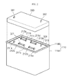
- FIG. 1 illustrates a perspective view of a secondary battery according to an embodiment of the invention
- FIG. 2 illustrates a perspective view of a cover and a case according to an embodiment of the invention assembled with each other
- FIG. 3 illustrates a cross-sectional view taken along the line I-I' of FIG. 1
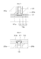
- FIG. 4 illustrates an enlarged view of a portion A of FIG. 3
- FIG. 5 illustrates an enlarged view of a portion B of FIG. 3
- FIG. 6 illustrates an enlarged view of a portion C of FIG. 3
- FIG. 7 illustrates a cross-sectional view taken along the line II-II' of FIG. 1
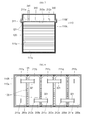
- FIGS. 9(a) and 9(b) illustrate a plan view and a cross-sectional view of a cap plate according to an embodiment of the invention.
- the secondary battery 1000 may include a case 100, an electrode assembly 200 and a cap assembly 300.
- the case 100 may include a body part 110A, an extension part 110B and partition walls 120.
- the body part 110A may accommodate the electrode assembly 200 and may be shaped of, e.g., in a shape of, a rectangular parallelepiped having a top opening.
- the body part 110A may include a first internal layer 111, a first functional layer 112 and a first external layer 113.
- the first internal layer 111 which may form the innermost structure of the body part 110A, may be made of a plastic material.
- the first functional layer 112 which may be interposed between the first internal layer 111 and the first external layer 113, may include one or more of a metal or an inorganic compound.
- the first functional layer 112 may be formed as a metal-inorganic compound based thin film or a metal foil or sheet between the first internal layer 111 and the first external layer 113.
- the first functional layer 112 may be formed by one of chemical vapor deposition (CVD), physical vapor deposition (PVD), atomic layer deposition (ALD) and plating.
- CVD chemical vapor deposition
- PVD physical vapor deposition
- ALD atomic layer deposition
- plating plating.
- the first functional layer 112 may be formed by interposing the metal foil or sheet between the first internal layer 111 and the first external layer 113 using multiple injection molds.
- the first external layer 113 which may form the outermost structure of the body part 110A, may be made of a plastic material.
- the first external layer 113 may be formed using a material demonstrating little reactivity with the electrolyte accommodated in the case 100 and having an insulating property.
- the first functional layer 112 may block moisture or gases.
- the first internal layer 111 and the first external layer 113 may support the first functional layer 112.
- the extension part 110B may extend from the outer periphery of a top end of the body part 110A and may protrude higher than the top end of the body part 110A.
- the extension part 110B may be formed along the outer periphery of the top end of the body part 110A in the form of a sidewall surrounding the outer periphery of a top end of the body part 110A, and a stepped portion 110a may be formed at the top end of the body part 110A by the extension part 110B.
- the extension part 110B may be formed to extend from the body part 110A, and the extension part 110B may include the first internal layer 111, the first functional layer 112 and the first external layer 113, like the body part 110A.
- the case 100 may be formed such that functional layers made of a metal or/and inorganic compound may be inserted into a plastic case, and the case 100 may be advantageous in view of degrees of freedom in shape, lightness in weight, and manufacturing costs, compared to a comparative metal case, while achieving the same strength, vapor resistance, swelling control, chemical resistance, abrasion resistance, and heat dissipation.
- the partition walls 120 may include a plurality of partition walls, for example, a plurality of accommodating spaces S1, S2, S3, S4 and S5, installed in the case 100.
- first to fifth accommodating spaces S1, S2, S3, S4 and S5 may be formed in the case 100 by four partition walls 120.
- the partition walls 120 may impregnate, e.g., may be impregnated with, the electrolyte accommodated in the first to fifth accommodating spaces S1, S2, S3, S4 and S5, and may provide the accommodated electrolyte to the first to fifth accommodating spaces S1, S2, S3, S4 and S5.
- the electrolyte accommodated in the case 100 may be exhausted over the passage of time, and amounts or concentrations of the electrolyte may vary.
- the electrolyte accommodated in an accommodating space may be isolated from the electrolyte accommodated in another accommodating space adjacent to the accommodating space, and a dispersion difference of the electrolyte may be created among the accommodating spaces.
- a significant difference in the electrolyte exhausted may be one of factors of degrading battery cell performance.
- some of the electrolyte may be impregnated in the partition walls 120.
- a solvent and a salt of the electrolyte impregnated in the partition walls 120 may be transferred to the accommodating space accommodating the electrolyte having a relatively low concentration.
- the solvent and the salt of the electrolyte impregnated in the partition walls 120 may be transferred to the accommodating space by an osmotic pressure.
- the partition walls 120 may cut off movement of electrons among the first to fifth accommodating spaces S1, S2, S3, S4 and S5.
- the partition walls 120 may include organic materials, inorganic materials or organic/inorganic materials.
- each of the partition walls 120 may be formed as a membrane-type porous layer including one or more of polyurethane or oriented polystyrene (OPS).
- OPS oriented polystyrene
- Each of the partition walls 120 formed as a thin film or a metal foil or sheet may have an increased thickness in a state in which the electrolyte is impregnated therein, and a tolerance between cells may be minimized.
- a first O ring or a gasket 121 may be coupled to the edge of each of the partition walls 120.
- the first O ring or the gasket 121 may seal portions between each of the partition walls 120 and the case 100 and between each of the partition walls 120 and the cap assembly 300.
- the partition walls 120 may be configured to cut off movement of electrons among the accommodating spaces, while the electrolyte is shared by the accommodating spaces, and degradation in cell performance due to, for example, a significant difference in the exhausted electrolyte among the accommodating spaces, may be minimized.
- a first insertion groove 111a may be formed in the first internal layer 111, and as illustrated in FIGS. 6 and 9 , a second insertion groove 310a may be formed in a bottom surface of a cap plate 310.
- the first and second insertion grooves 111a and 310a may be formed to correspond to edges of the partition walls 120. The edges of the partition walls 120 may be inserted into the first and second insertion grooves 111a and 310a together with the first O ring or the gasket 121 to be engaged with each other.
- partition walls 120 may be inserted into the first insertion groove 111a and top edges of the partition walls 120 may be inserted into the second insertion groove 310a, and the partition walls 120 may be more tightly coupled to the case 100. In addition, the partition walls 120 may be more easily installed in the case 100.
- the electrode assembly 200 may include first to fifth electrode assemblies 200a, 200b, 200c, 200d and 200e and may be accommodated in the case 100 together with an electrolyte.
- the first to fifth electrode assemblies 200a, 200b, 200c, 200d and 200e may be accommodated one by one in the first to fifth accommodating spaces S1, S2, S3, S4 and S5, respectively.
- the first electrode assembly 200a may be accommodated in the first accommodating space S 1
- the second electrode assembly 200b may be accommodated in the second accommodating space S2
- the third electrode assembly 200c may be accommodated in the third accommodating space S3
- the fourth electrode assembly 200d may be accommodated in the fourth accommodating space S4
- the fifth electrode assembly 200e may be accommodated in the fifth accommodating space S5.
- Each of the first to fifth electrode assemblies 200a, 200b, 200c, 200d and 200e may be configured by winding or stacking a first electrode plate, a second electrode plate and a separator.
- the first to fifth electrode assemblies 200a, 200b, 200c, 200d and 200e may include first electrode tabs 211 a, 211 b, 211 c, 211 d and 211e, which may be electrically connected to the first electrode plate, and second electrode tabs 212a, 212b, 212c, 212d and 212e, which may be electrically connected to the second electrode plate.
- the first electrode tabs 211a, 211b, 211c, 211d and 211e and the second electrode tabs 212a, 212b, 212c, 212d and 212e may be exposed to a top portion of the cap plate 310 while passing through the cap plate 310.
- the cap assembly 300 may include the cap plate 310, a plurality of connection tabs 321, a cover 330, a first electrode terminal 341 and a second electrode terminal 342.
- the cap plate 310 may seal the top portion of the case 100, which may be opened, and the cap plate 310 may be sized and shaped to correspond to the top portion of the case 100.
- the cap plate 310 may be shaped of, e.g., in a shape of, a rectangular plate.
- the second insertion groove 310a may be formed on the bottom surface of the cap plate 310 to insert the top edges of the partition walls 120 thereinto.
- a plurality of tab holes 310b allowing the respective electrode tabs to pass therethrough may be formed at portions of the cap plate 310, the portions corresponding to the first electrode tabs 211a, 211b, 211c, 211d and 211e and the second electrode tabs 212a, 212b, 212c, 212d and 212e.
- a third gasket 313 may be assembled with the tab holes 310b, and the tab holes 310b may be more tightly sealed.
- a second O ring or a gasket 311 may be coupled to the edge of the cap plate 310, and the top portion of the case 100 may be more tightly sealed.
- the cap plate 310 may be inserted into the extension part 110B and may then be mounted on the top end of the body part 110A to then be coupled to the case 100. As illustrated in FIG. 4 , the stepped portion 110a may be formed at the top end of the body part 110A by the extension part 110B, and the cap plate 310 may be assembled on the stepped portion 110a.
- the first connection tabs 321 may be electrically connected to the first to fifth electrode assemblies 200a, 200b, 200c, 200d and 200e through the first electrode tabs 211a, 211 b, 211c, 211d and 211e and the second electrode tabs 212a, 212b, 212c, 212d and 212e.
- the second electrode tab 212a of the first electrode assembly 200a may be connected to the first electrode tab 21 1b of the second electrode assembly 200b
- the second electrode tab 212b of the second electrode assembly 200b may be connected to the first electrode tab 211c of the third electrode assembly 200c
- the second electrode tab 212c of the third electrode assembly 200c may be connected to the first electrode tab 211d of the fourth electrode assembly 200d
- the second electrode tab 212d of the fourth electrode assembly 200d may be connected to the first electrode tab 211e of the fifth electrode assembly 200e
- the first to fifth electrode assemblies 200a, 200b, 200c, 200d and 200e may be connected to one another in series.
- the cover 330 may have an opened bottom portion shaped of, e.g., in a shape of, a substantially rectangular parallelepiped and may be coupled to the top end of the case 100 to allow the opened bottom portion of the cover 330 to face the opened top portion of the case 100.
- the cover 330 and the extension part 110B may be welded to each other.
- the cover 330 may include a second internal layer 331, a second functional layer 332 and a first external layer 333.
- the second internal layer 331, which may form the innermost structure of the cover 330, may be made of a plastic material.
- the second functional layer 332, which may be interposed between the second internal layer 331 and the second external layer 333, may include one or more of a metal or an inorganic compound.
- the second functional layer 332 may be formed as a metal-inorganic compound based thin film or a metal foil or sheet between the second internal layer 331 and the second external layer 333.
- the second functional layer 332 may be formed by one of chemical vapor deposition (CVD), physical vapor deposition (PVD), atomic layer deposition (ALD) and plating.
- CVD chemical vapor deposition
- PVD physical vapor deposition
- ALD atomic layer deposition
- plating plating.
- the second functional layer 332 may be formed by interposing the metal foil or sheet between the second internal layer 331 and the second external layer 333.
- the second external layer 333 which may form the outermost structure of the body part 110A, may be made of a plastic material.
- the second external layer 333 may be formed using a material demonstrating little reactivity with the electrolyte accommodated in the case 100 and having an insulating property.
- the second functional layer 332 may block moisture or gases.
- the second internal layer 331 and the second external layer 333 may support the second functional layer 332.
- a plurality of terminal holes 330a may be formed in the cover 330.
- the first electrode terminal 341 and the second electrode terminal 342 may pass through the terminal holes 330a, a fourth gasket 334 may be assembled with the cover 330, and the cover 330 may be more tightly sealed.
- the first electrode terminal 341 may be electrically connected to the first electrode tab 211a of the first electrode assembly 200a.
- the second electrode terminal 342 may be electrically connected to the second electrode tab 212e of the fifth electrode assembly 200e.
- the first electrode tab 211a of the first electrode assembly 200a may be a terminal having a highest voltage level among the first to fifth electrode assemblies 200a, 200b, 200c, 200d and 200e connected to one another in series
- the second electrode tab 212e of the fifth electrode assembly 200e may be a terminal having a lowest voltage level among the first to fifth electrode assemblies 200a, 200b, 200c, 200d and 200e.
- FIG. 10 illustrates a plan view of a secondary battery according to another embodiment.
- a plurality of electrode assemblies may be accommodated in a single accommodating space.
- the plurality of electrode assemblies accommodated in the single accommodating space may be connected to one another in parallel, the electrode assemblies between adjacent accommodating spaces may be connected to one another in series, and the secondary battery according to the present embodiment may further include second_first connection tabs 322 and second_second connection tabs 323, unlike the secondary battery according to the previous embodiment.
- the second_first connection tabs 322 may connect first electrode tabs of the electrode assemblies accommodated in one single accommodating space to one another, and the second_second connection tabs 323 may connect second electrode tabs of the electrode assemblies accommodated in one single accommodating space to one another.
- the first electrode tab 211a1 of the first_first electrode assembly 200a1, the first electrode tab 211a2 of the first_second electrode assembly 200a2, and the first electrode tab 211 a3 of the first_third electrode assembly 200a3 may be connected to one another by the second_first connection tab and the first electrode tab 212a1 of the first_first electrode assembly 200a1, the first electrode tab 212a2 of the first_second electrode assembly 200a2, and the first electrode tab 212a3 of the first_third electrode assembly 200a3 may be connected to one another by the second_second connection tab 323, and the first_first to first_third electrode assemblies 200a1, 200a2 and 200a3 may be connected to one another in parallel.
- partition walls separating battery cells from one another may be configured to cut off movement of electrons while sharing an electrolyte among the accommodating spaces, and cell performance may be minimized from being degraded due to, for example, a significant difference in the exhausted electrolyte among the accommodating spaces.
- An external case may be formed such that functional layers made of a metal or/and inorganic compound may be inserted into a plastic case, and the external case may be advantageous in view of degrees of freedom in shape, lightness in weight, and manufacturing costs, compared to a comparative metal case, while achieving the same strength, vapor resistance, swelling control, chemical resistance, abrasion resistance, and heat dissipation.
Landscapes
- Chemical & Material Sciences (AREA)
- Chemical Kinetics & Catalysis (AREA)
- Electrochemistry (AREA)
- General Chemical & Material Sciences (AREA)
- Inorganic Chemistry (AREA)
- Sealing Battery Cases Or Jackets (AREA)
- Secondary Cells (AREA)
- Engineering & Computer Science (AREA)
- Manufacturing & Machinery (AREA)
Abstract
Description
- The invention relates to a secondary battery.
- A comparative battery pack having a multiple series/parallel structure may be manufactured by utilizing multiple unit cells, and connecting the unit cells to one another in series and in parallel.
- Inorder to manufacture a comparative multiple series/parallel battery pack, an increased number of components and many process steps may be required in housing the battery cells, and may lead to an increase in the manufacturing cost of the multiple series/parallel battery pack.
- In a cell-pack integrated structure, unit cells and an electrolyte may be directly accommodated in a single case. A plurality of cell chambers may be provided to separate unit cells from each other in the battery pack.
- However, the electrolyte accommodated in the case may be exhausted over the passage of time, and amounts or concentrations of the electrolyte may vary. For example, the electrolyte accommodated in an accommodating space may be isolated from the electrolyte accommodated in another accommodating space adjacent to the accommodating space, and a dispersion difference of the electrolyte may be created among the accommodating spaces. A significant difference in the electrolyte exhausted may degrade battery cell performance.
- The invention sets out to provide a secondary battery, that may minimize the number of components and the manufacturing cost and may minimize degradation of cell performance due to, for example, a dispersion difference of an electrolyte.
- Embodiments of the invention may be realized by providing a secondary battery, including a case having one or more partition walls providing a plurality of accommodating spaces; a plurality of electrode assemblies in the accommodating spaces with an electrolyte, the plurality of electrode assemblies including electrode tabs; and a cap assembly including a cap plate sealing a top portion of the case, the cap assembly having the electrode tabs drawn therefrom and first connection tabs electrically connecting the plurality of electrode assemblies through the electrode tabs, the partition walls being impregnated with the electrolyte.
- The partition walls may cut off movement of electrons among the accommodating spaces and may transfer a solvent and a salt of the electrolyte to adjacent accommodating spaces among the plurality of accommodating spaces.
- Each of the partition walls may be a membrane-type porous layer including one or more of polyurethane or oriented polystyrene (OPS).
- The case may include a body part for accommodating the plurality of electrode assemblies and an extension part extending from an outer periphery of a top end of the body part and protruding higher than the top end of the body part, the case may include a first internal layer, a first external layer, and a first functional layer interposed between the first internal layer and the first external layer, the first internal layer and the first external layer may include a plastic material, and the first functional layer may include one or more of a metal or an inorganic compound.
- The cap assembly may further include a cover coupled to the top end of the case, the cover covering the cap plate and an electrode terminal electrically connected to the electrode tabs and exposed to the outside while passing through the cover, the cover may include a second internal layer, a second external layer, and a second functional layer interposed between the second internal layer and the second external layer, the second internal layer and the second external layer may include a plastic material, and the second functional layer may include one or more of a metal or an inorganic compound.
- The case and the cover may be coupled to each other such that the extension part of the case and a bottom portion of the cover are welded to each other.
- A stepped portion may be formed at the top end of the body part by the extension part, an O ring or a gasket may be coupled to an edge of the cap plate, and the cap plate may be coupled to the stepped portion with the O ring or the gasket.
- A plurality of insertion grooves corresponding to edges of the partition walls may be on an inner surface of the case and a bottom surface of the cap plate, the O ring or the gasket may be coupled to the edges of the partition walls, and the partition walls may be engaged with the insertion grooves with the O ring or the gasket.
- Among the plurality of electrode assemblies, the electrode assemblies positioned between each of the accommodating spaces may be connected to one another in series by the first connection tabs.
- At least some of the above and other features of the invention are set out in the claims.
- The cap assembly may further include second connection tabs, and when the plurality of electrode assemblies are in the accommodating spaces, respectively, the electrode assemblies in the respective accommodating spaces may be connected to one another in parallel by the second connection tabs.
- Features of the invention will be made more apparent to those of skill in the art by describing in detail exemplary embodiments with reference to the attached drawings in which:
-
FIG. 1 illustrates a perspective view of a secondary battery according to an embodiment of the invention; -
FIG. 2 illustrates a perspective view of a cover and a case according to an embodiment of the invention assembled with each other; -
FIG. 3 illustrates a cross-sectional view taken along the line I-I' ofFIG. 1 ; -
FIG. 4 illustrates an enlarged view of a portion A ofFIG. 3 ; -
FIG. 5 illustrates an enlarged view of a portion B ofFIG. 3 ; -
FIG. 6 illustrates an enlarged view of a portion C ofFIG. 3 ; -
FIG. 7 illustrates a cross-sectional view taken along the line II-II' ofFIG. 1 ; -
FIG. 8 illustrates a plan view of the secondary battery from which the cover and the case according to an embodiment of the invention are removed; -
FIGS. 9(a) and 9(b) illustrate a plan view and a cross-sectional view of a cap plate according to an embodiment; and -
FIG. 10 illustrates a plan view of a secondary battery according to another embodiment of the invention. - Example embodiments of the invention will now be described more fully hereinafter with reference to the accompanying drawings; however, the invention may be embodied in different forms and should not be construed as limited to the embodiments set forth herein. Rather, these embodiments are provided so that this disclosure will be thorough and will convey implementations of the invention to those skilled in the art.
- In the drawing figures, the dimensions of layers and regions may be exaggerated for clarity of illustration. Like reference numerals refer to like elements throughout.
-
FIG. 1 illustrates a perspective view of a secondary battery according to an embodiment of the invention,FIG. 2 illustrates a perspective view of a cover and a case according to an embodiment of the invention assembled with each other,FIG. 3 illustrates a cross-sectional view taken along the line I-I' ofFIG. 1 ,FIG. 4 illustrates an enlarged view of a portion A ofFIG. 3 ,FIG. 5 illustrates an enlarged view of a portion B ofFIG. 3 ,FIG. 6 illustrates an enlarged view of a portion C ofFIG. 3 ,FIG. 7 illustrates a cross-sectional view taken along the line II-II' ofFIG. 1 ,FIG. 8 illustrates a plan view of the secondary battery from which the cover and the case according to an embodiment of the invention are removed, andFIGS. 9(a) and 9(b) illustrate a plan view and a cross-sectional view of a cap plate according to an embodiment of the invention. - Referring to
FIGS. 1 to 9 , thesecondary battery 1000 according to an embodiment of the invention may include a case 100, anelectrode assembly 200 and acap assembly 300. - As illustrated in
FIG. 3 , the case 100 may include abody part 110A, anextension part 110B andpartition walls 120. - The
body part 110A may accommodate theelectrode assembly 200 and may be shaped of, e.g., in a shape of, a rectangular parallelepiped having a top opening. Thebody part 110A may include a firstinternal layer 111, a firstfunctional layer 112 and a firstexternal layer 113. - The first
internal layer 111, which may form the innermost structure of thebody part 110A, may be made of a plastic material. - The first
functional layer 112, which may be interposed between the firstinternal layer 111 and the firstexternal layer 113, may include one or more of a metal or an inorganic compound. - For example, the first
functional layer 112 may be formed as a metal-inorganic compound based thin film or a metal foil or sheet between the firstinternal layer 111 and the firstexternal layer 113. When the firstfunctional layer 112 is formed as a metal-inorganic compound based thin film, the firstfunctional layer 112 may be formed by one of chemical vapor deposition (CVD), physical vapor deposition (PVD), atomic layer deposition (ALD) and plating. When the firstfunctional layer 112 is formed as a metal foil or sheet, the firstfunctional layer 112 may be formed by interposing the metal foil or sheet between the firstinternal layer 111 and the firstexternal layer 113 using multiple injection molds. - The first
external layer 113, which may form the outermost structure of thebody part 110A, may be made of a plastic material. For example, the firstexternal layer 113 may be formed using a material demonstrating little reactivity with the electrolyte accommodated in the case 100 and having an insulating property. - The first
functional layer 112 may block moisture or gases. The firstinternal layer 111 and the firstexternal layer 113 may support the firstfunctional layer 112. - The
extension part 110B may extend from the outer periphery of a top end of thebody part 110A and may protrude higher than the top end of thebody part 110A. Theextension part 110B may be formed along the outer periphery of the top end of thebody part 110A in the form of a sidewall surrounding the outer periphery of a top end of thebody part 110A, and astepped portion 110a may be formed at the top end of thebody part 110A by theextension part 110B. - The
extension part 110B may be formed to extend from thebody part 110A, and theextension part 110B may include the firstinternal layer 111, the firstfunctional layer 112 and the firstexternal layer 113, like thebody part 110A. - As described above, the case 100 may be formed such that functional layers made of a metal or/and inorganic compound may be inserted into a plastic case, and the case 100 may be advantageous in view of degrees of freedom in shape, lightness in weight, and manufacturing costs, compared to a comparative metal case, while achieving the same strength, vapor resistance, swelling control, chemical resistance, abrasion resistance, and heat dissipation.
- The
partition walls 120 may include a plurality of partition walls, for example, a plurality of accommodating spaces S1, S2, S3, S4 and S5, installed in the case 100. For example, as illustrated inFIG. 3 , first to fifth accommodating spaces S1, S2, S3, S4 and S5 may be formed in the case 100 by fourpartition walls 120. - The
partition walls 120 may impregnate, e.g., may be impregnated with, the electrolyte accommodated in the first to fifth accommodating spaces S1, S2, S3, S4 and S5, and may provide the accommodated electrolyte to the first to fifth accommodating spaces S1, S2, S3, S4 and S5. - The electrolyte accommodated in the case 100 may be exhausted over the passage of time, and amounts or concentrations of the electrolyte may vary. For example, the electrolyte accommodated in an accommodating space may be isolated from the electrolyte accommodated in another accommodating space adjacent to the accommodating space, and a dispersion difference of the electrolyte may be created among the accommodating spaces. A significant difference in the electrolyte exhausted may be one of factors of degrading battery cell performance.
- According to the present embodiment, in order to solve a problem due to, for example, the significant difference in the electrolyte exhausted, when the electrolyte accommodated in each of the first to fifth accommodating spaces S1, S2, S3, S4 and S5 has a constant concentration, some of the electrolyte may be impregnated in the
partition walls 120. When there is a concentration difference between electrolytes accommodated in the first to fifth accommodating spaces S1, S2, S3, S4 and S5, a solvent and a salt of the electrolyte impregnated in thepartition walls 120 may be transferred to the accommodating space accommodating the electrolyte having a relatively low concentration. The solvent and the salt of the electrolyte impregnated in thepartition walls 120 may be transferred to the accommodating space by an osmotic pressure. Thepartition walls 120 may cut off movement of electrons among the first to fifth accommodating spaces S1, S2, S3, S4 and S5. - The
partition walls 120 may include organic materials, inorganic materials or organic/inorganic materials. For example, each of thepartition walls 120 may be formed as a membrane-type porous layer including one or more of polyurethane or oriented polystyrene (OPS). - Each of the
partition walls 120 formed as a thin film or a metal foil or sheet may have an increased thickness in a state in which the electrolyte is impregnated therein, and a tolerance between cells may be minimized. - A first O ring or a
gasket 121 may be coupled to the edge of each of thepartition walls 120. In order to prevent the electrolyte from being unnecessarily shared by the accommodating spaces, the first O ring or thegasket 121 may seal portions between each of thepartition walls 120 and the case 100 and between each of thepartition walls 120 and thecap assembly 300. - As described above, the
partition walls 120 may be configured to cut off movement of electrons among the accommodating spaces, while the electrolyte is shared by the accommodating spaces, and degradation in cell performance due to, for example, a significant difference in the exhausted electrolyte among the accommodating spaces, may be minimized. - As illustrated in
FIGS. 5 and7 , afirst insertion groove 111a may be formed in the firstinternal layer 111, and as illustrated inFIGS. 6 and9 , asecond insertion groove 310a may be formed in a bottom surface of acap plate 310. The first andsecond insertion grooves partition walls 120. The edges of thepartition walls 120 may be inserted into the first andsecond insertion grooves gasket 121 to be engaged with each other. Side and bottom edges of thepartition walls 120 may be inserted into thefirst insertion groove 111a and top edges of thepartition walls 120 may be inserted into thesecond insertion groove 310a, and thepartition walls 120 may be more tightly coupled to the case 100. In addition, thepartition walls 120 may be more easily installed in the case 100. - As illustrated in
FIG. 3 , theelectrode assembly 200 may include first tofifth electrode assemblies fifth electrode assemblies first electrode assembly 200a may be accommodated in the firstaccommodating space S 1, thesecond electrode assembly 200b may be accommodated in the second accommodating space S2, thethird electrode assembly 200c may be accommodated in the third accommodating space S3, thefourth electrode assembly 200d may be accommodated in the fourth accommodating space S4, and thefifth electrode assembly 200e may be accommodated in the fifth accommodating space S5. - Each of the first to
fifth electrode assemblies fifth electrode assemblies first electrode tabs second electrode tabs - The
first electrode tabs second electrode tabs cap plate 310 while passing through thecap plate 310. - The
cap assembly 300 may include thecap plate 310, a plurality ofconnection tabs 321, acover 330, afirst electrode terminal 341 and asecond electrode terminal 342. - The
cap plate 310 may seal the top portion of the case 100, which may be opened, and thecap plate 310 may be sized and shaped to correspond to the top portion of the case 100. For example, thecap plate 310 may be shaped of, e.g., in a shape of, a rectangular plate. - The
second insertion groove 310a may be formed on the bottom surface of thecap plate 310 to insert the top edges of thepartition walls 120 thereinto. A plurality of tab holes 310b allowing the respective electrode tabs to pass therethrough may be formed at portions of thecap plate 310, the portions corresponding to thefirst electrode tabs second electrode tabs third gasket 313 may be assembled with the tab holes 310b, and the tab holes 310b may be more tightly sealed. - A second O ring or a
gasket 311 may be coupled to the edge of thecap plate 310, and the top portion of the case 100 may be more tightly sealed. - The
cap plate 310 may be inserted into theextension part 110B and may then be mounted on the top end of thebody part 110A to then be coupled to the case 100. As illustrated inFIG. 4 , the steppedportion 110a may be formed at the top end of thebody part 110A by theextension part 110B, and thecap plate 310 may be assembled on the steppedportion 110a. - The
first connection tabs 321 may be electrically connected to the first tofifth electrode assemblies first electrode tabs second electrode tabs - Among the plurality of
connection tabs 321, for example, thesecond electrode tab 212a of thefirst electrode assembly 200a may be connected to the first electrode tab 21 1b of thesecond electrode assembly 200b, thesecond electrode tab 212b of thesecond electrode assembly 200b may be connected to thefirst electrode tab 211c of thethird electrode assembly 200c, thesecond electrode tab 212c of thethird electrode assembly 200c may be connected to thefirst electrode tab 211d of thefourth electrode assembly 200d, and thesecond electrode tab 212d of thefourth electrode assembly 200d may be connected to thefirst electrode tab 211e of thefifth electrode assembly 200e, and the first tofifth electrode assemblies - The
cover 330 may have an opened bottom portion shaped of, e.g., in a shape of, a substantially rectangular parallelepiped and may be coupled to the top end of the case 100 to allow the opened bottom portion of thecover 330 to face the opened top portion of the case 100. For example, in a state in which the bottom portion of thecover 330 is inserted into theextension part 110B of the case 100, thecover 330 and theextension part 110B may be welded to each other. - As illustrated in
FIG. 3 , thecover 330 may include a secondinternal layer 331, a secondfunctional layer 332 and a firstexternal layer 333. - The second
internal layer 331, which may form the innermost structure of thecover 330, may be made of a plastic material. - The second
functional layer 332, which may be interposed between the secondinternal layer 331 and the secondexternal layer 333, may include one or more of a metal or an inorganic compound. - For example, the second
functional layer 332 may be formed as a metal-inorganic compound based thin film or a metal foil or sheet between the secondinternal layer 331 and the secondexternal layer 333. When the secondfunctional layer 332 is formed as a metal-inorganic compound based thin film, the secondfunctional layer 332 may be formed by one of chemical vapor deposition (CVD), physical vapor deposition (PVD), atomic layer deposition (ALD) and plating. When the secondfunctional layer 332 is formed as a metal foil or sheet, the second functional layer 332may be formed by interposing the metal foil or sheet between the secondinternal layer 331 and the secondexternal layer 333. - The second
external layer 333, which may form the outermost structure of thebody part 110A, may be made of a plastic material. For example, the secondexternal layer 333 may be formed using a material demonstrating little reactivity with the electrolyte accommodated in the case 100 and having an insulating property. - The second
functional layer 332 may block moisture or gases. The secondinternal layer 331 and the secondexternal layer 333 may support the secondfunctional layer 332. - A plurality of
terminal holes 330a may be formed in thecover 330. Thefirst electrode terminal 341 and thesecond electrode terminal 342 may pass through theterminal holes 330a, afourth gasket 334 may be assembled with thecover 330, and thecover 330 may be more tightly sealed. - The
first electrode terminal 341 may be electrically connected to thefirst electrode tab 211a of thefirst electrode assembly 200a. Thesecond electrode terminal 342 may be electrically connected to thesecond electrode tab 212e of thefifth electrode assembly 200e. - The
first electrode tab 211a of thefirst electrode assembly 200a may be a terminal having a highest voltage level among the first tofifth electrode assemblies second electrode tab 212e of thefifth electrode assembly 200e may be a terminal having a lowest voltage level among the first tofifth electrode assemblies -
FIG. 10 illustrates a plan view of a secondary battery according to another embodiment. - In the embodiment illustrated in
FIG. 10 , unlike in the previous embodiment, a plurality of electrode assemblies may be accommodated in a single accommodating space. The plurality of electrode assemblies accommodated in the single accommodating space may be connected to one another in parallel, the electrode assemblies between adjacent accommodating spaces may be connected to one another in series, and the secondary battery according to the present embodiment may further includesecond_first connection tabs 322 andsecond_second connection tabs 323, unlike the secondary battery according to the previous embodiment. - The
second_first connection tabs 322 may connect first electrode tabs of the electrode assemblies accommodated in one single accommodating space to one another, and thesecond_second connection tabs 323 may connect second electrode tabs of the electrode assemblies accommodated in one single accommodating space to one another. - Among the first_first to first_third electrode assemblies 200a1, 200a2 and 200a3, for example, the first electrode tab 211a1 of the first_first electrode assembly 200a1, the first electrode tab 211a2 of the first_second electrode assembly 200a2, and the first electrode tab 211 a3 of the first_third electrode assembly 200a3 may be connected to one another by the second_first connection tab and the first electrode tab 212a1 of the first_first electrode assembly 200a1, the first electrode tab 212a2 of the first_second electrode assembly 200a2, and the first electrode tab 212a3 of the first_third electrode assembly 200a3 may be connected to one another by the
second_second connection tab 323, and the first_first to first_third electrode assemblies 200a1, 200a2 and 200a3 may be connected to one another in parallel. - According to the embodiment, in a cell-pack integrated structure, partition walls separating battery cells from one another may be configured to cut off movement of electrons while sharing an electrolyte among the accommodating spaces, and cell performance may be minimized from being degraded due to, for example, a significant difference in the exhausted electrolyte among the accommodating spaces.
- An external case may be formed such that functional layers made of a metal or/and inorganic compound may be inserted into a plastic case, and the external case may be advantageous in view of degrees of freedom in shape, lightness in weight, and manufacturing costs, compared to a comparative metal case, while achieving the same strength, vapor resistance, swelling control, chemical resistance, abrasion resistance, and heat dissipation.
- Example embodiments have been disclosed herein, and although specific terms are employed, they are used and are to be interpreted in a generic and descriptive sense only and not for purpose of limitation. In some instances, as would be apparent to one of skill in the art as of the filing of the present application, features, characteristics, and/or elements described in connection with a particular embodiment may be used singly or in combination with features, characteristics, and/or elements described in connection with other embodiments unless otherwise specifically indicated. Accordingly, it will be understood by those of skill in the art that various changes in form and details may be made without departing from the scope of the present invention as set forth in the following claims.
Claims (10)
- A secondary battery, comprising:a case having one or more partition walls providing a plurality of accommodating spaces;a plurality of electrode assemblies in the accommodating spaces with an electrolyte, the plurality of electrode assemblies including electrode tabs; anda cap assembly including a cap plate sealing a top portion of the case, the cap assembly having the electrode tabs drawn therefrom and first connection tabs electrically connecting the plurality of electrode assemblies through the electrode tabs,the partition walls being impregnated with the electrolyte.
- A secondary battery as claimed in claim 1, wherein the partition walls are adapted to cut off movement of electrons among the accommodating spaces and transfer a solvent and a salt of the electrolyte to adjacent accommodating spaces among the plurality of accommodating spaces.
- A secondary battery as claimed in claim 1 or 2, wherein each of the partition walls is a membrane-type porous layer including one or more of polyurethane or oriented polystyrene (OPS).
- A secondary battery as claimed in any proceeding claim, wherein:the case includes a body part for accommodating the plurality of electrode assemblies and an extension part extending from an outer periphery of a top end of the body part and protruding higher than the top end of the body part,the case includes a first internal layer, a first external layer, and a first functional layer interposed between the first internal layer and the first external layer,the first internal layer and the first external layer include a plastic material, andthe first functional layer includes one or more of a metal or an inorganic compound.
- A secondary battery as claimed in claim 4, wherein:the cap assembly further includes a cover coupled to the top end of the case, the cover covering the cap plate and an electrode terminal electrically connected to the electrode tabs and exposed to the outside while passing through the cover,the cover includes a second internal layer, a second external layer, and a second functional layer interposed between the second internal layer and the second external layer,the second internal layer and the second external layer include a plastic material, andthe second functional layer includes one or more of a metal or an inorganic compound.
- A secondary battery as claimed in claim 5, wherein the case and the cover are coupled to each other such that the extension part of the case and a bottom portion of the cover are welded to each other.
- A secondary battery as claimed in claim 4, 5 or 6 wherein:a stepped portion is formed at the top end of the body part by the extension part,an O ring or a gasket is coupled to an edge of the cap plate, andthe cap plate is coupled to the stepped portion with the O ring or the gasket.
- A secondary battery as claimed in claim 7, wherein:a plurality of insertion grooves corresponding to edges of the partition walls are on an inner surface of the case and a bottom surface of the cap plate,the O ring or the gasket is coupled to the edges of the partition walls, andthe partition walls are engaged with the insertion grooves with the O ring or the gasket.
- A secondary battery as claimed in any proceeding claim, wherein among the plurality of electrode assemblies, the electrode assemblies positioned between each of the accommodating spaces are connected to one another in series by the first connection tabs.
- A secondary battery as claimed in claim 9, wherein:the cap assembly further includes second connection tabs, andwhen the plurality of electrode assemblies are in the accommodating spaces, respectively, the electrode assemblies in the respective accommodating spaces are connected to one another in parallel by the second connection tabs.
Applications Claiming Priority (1)
| Application Number | Priority Date | Filing Date | Title |
|---|---|---|---|
| KR1020150092171A KR102421419B1 (en) | 2015-06-29 | 2015-06-29 | A secondary battery |
Publications (2)
| Publication Number | Publication Date |
|---|---|
| EP3113242A1 true EP3113242A1 (en) | 2017-01-04 |
| EP3113242B1 EP3113242B1 (en) | 2017-10-04 |
Family
ID=54545033
Family Applications (1)
| Application Number | Title | Priority Date | Filing Date |
|---|---|---|---|
| EP15194913.8A Active EP3113242B1 (en) | 2015-06-29 | 2015-11-17 | Secondary battery |
Country Status (4)
| Country | Link |
|---|---|
| US (1) | US10003064B2 (en) |
| EP (1) | EP3113242B1 (en) |
| KR (1) | KR102421419B1 (en) |
| CN (1) | CN106299179B (en) |
Cited By (1)
| Publication number | Priority date | Publication date | Assignee | Title |
|---|---|---|---|---|
| EP4358260A4 (en) * | 2022-06-27 | 2025-06-18 | LG Energy Solution, Ltd. | Battery pack |
Families Citing this family (7)
| Publication number | Priority date | Publication date | Assignee | Title |
|---|---|---|---|---|
| KR102248228B1 (en) | 2017-09-26 | 2021-05-03 | 주식회사 엘지화학 | Battery module housing by applying Electromagnetic pulse technology and Method for manufacturing the same |
| KR102725463B1 (en) * | 2018-12-20 | 2024-11-06 | 주식회사 엘지에너지솔루션 | Battery Pack Comprising Integral Battery Cell |
| US11128002B2 (en) * | 2019-02-12 | 2021-09-21 | ZAF Energy Systems, Incorporated | Monoblocs and monobloc batteries |
| CN112838333A (en) * | 2019-11-22 | 2021-05-25 | 比亚迪股份有限公司 | A battery, battery module, battery pack and automobile |
| KR102952860B1 (en) * | 2020-09-08 | 2026-04-15 | 닝더 엠프렉스 테크놀로지 리미티드 | Electrochemical devices and electronic devices |
| CN115642325A (en) * | 2021-07-20 | 2023-01-24 | Oppo广东移动通信有限公司 | Battery charging method and circuit, multi-cell battery, terminal equipment and electronic equipment |
| CN114300796B (en) * | 2021-12-30 | 2024-05-28 | 三一技术装备有限公司 | Battery cell |
Citations (5)
| Publication number | Priority date | Publication date | Assignee | Title |
|---|---|---|---|---|
| US1545328A (en) * | 1919-07-08 | 1925-07-07 | Philadelphia Storage Battery | Storage-battery container |
| US5464701A (en) * | 1995-02-27 | 1995-11-07 | Eagle-Picher Industries, Inc. | Leakproof, valve regulated, maintenance-free lead acid battery |
| US20060166087A1 (en) * | 2005-01-25 | 2006-07-27 | Toyota Jidosha Kabushiki Kaisha | Secondary battery |
| EP2357688A1 (en) * | 2008-12-10 | 2011-08-17 | Panasonic Corporation | Battery module and battery module assembly using same |
| EP2677587A1 (en) * | 2011-02-18 | 2013-12-25 | Shin-Kobe Electric Machinery Co., Ltd. | Secondary battery |
Family Cites Families (9)
| Publication number | Priority date | Publication date | Assignee | Title |
|---|---|---|---|---|
| DE8430246U1 (en) * | 1984-10-15 | 1985-01-24 | Accumulatorenwerke Hoppecke Carl Zoellner & Sohn GmbH & Co KG, 5790 Brilon | LEAD ACCUMULATOR |
| IL144832A (en) * | 2001-08-09 | 2005-06-19 | Polyrit | Thermal jacket for battery |
| JP5049436B2 (en) | 2001-09-28 | 2012-10-17 | パナソニック株式会社 | Assembled battery |
| US8216713B2 (en) | 2009-02-25 | 2012-07-10 | Sb Limotive Co., Ltd. | Battery housing formed with cooling passages and battery pack having the same |
| KR101106395B1 (en) * | 2009-10-15 | 2012-01-17 | 삼성에스디아이 주식회사 | Secondary Battery and Manufacturing Method Thereof |
| EP2521202B1 (en) | 2010-02-03 | 2016-06-08 | Panasonic Intellectual Property Management Co., Ltd. | Power source |
| DE102010024235B4 (en) * | 2010-06-18 | 2016-11-10 | Continental Automotive Gmbh | Battery cell and battery |
| JP6017139B2 (en) * | 2012-01-11 | 2016-10-26 | 株式会社東芝 | battery |
| US20140127551A1 (en) * | 2012-06-20 | 2014-05-08 | Robert Bosch Gmbh | Rechargeable battery and module of the same |
-
2015
- 2015-06-29 KR KR1020150092171A patent/KR102421419B1/en active Active
- 2015-10-07 US US14/876,849 patent/US10003064B2/en active Active
- 2015-11-17 EP EP15194913.8A patent/EP3113242B1/en active Active
- 2015-11-19 CN CN201510802570.7A patent/CN106299179B/en active Active
Patent Citations (5)
| Publication number | Priority date | Publication date | Assignee | Title |
|---|---|---|---|---|
| US1545328A (en) * | 1919-07-08 | 1925-07-07 | Philadelphia Storage Battery | Storage-battery container |
| US5464701A (en) * | 1995-02-27 | 1995-11-07 | Eagle-Picher Industries, Inc. | Leakproof, valve regulated, maintenance-free lead acid battery |
| US20060166087A1 (en) * | 2005-01-25 | 2006-07-27 | Toyota Jidosha Kabushiki Kaisha | Secondary battery |
| EP2357688A1 (en) * | 2008-12-10 | 2011-08-17 | Panasonic Corporation | Battery module and battery module assembly using same |
| EP2677587A1 (en) * | 2011-02-18 | 2013-12-25 | Shin-Kobe Electric Machinery Co., Ltd. | Secondary battery |
Cited By (1)
| Publication number | Priority date | Publication date | Assignee | Title |
|---|---|---|---|---|
| EP4358260A4 (en) * | 2022-06-27 | 2025-06-18 | LG Energy Solution, Ltd. | Battery pack |
Also Published As
| Publication number | Publication date |
|---|---|
| US10003064B2 (en) | 2018-06-19 |
| US20160380251A1 (en) | 2016-12-29 |
| KR20170002139A (en) | 2017-01-06 |
| KR102421419B1 (en) | 2022-07-15 |
| CN106299179A (en) | 2017-01-04 |
| CN106299179B (en) | 2020-08-04 |
| EP3113242B1 (en) | 2017-10-04 |
Similar Documents
| Publication | Publication Date | Title |
|---|---|---|
| EP3113242B1 (en) | Secondary battery | |
| KR102397123B1 (en) | Battery pack | |
| KR101627631B1 (en) | Rechargeable battery and module thereof | |
| US8865344B2 (en) | Rechargeable battery | |
| KR101201744B1 (en) | Rechargeable battery | |
| EP2849247B1 (en) | Rechargeable battery | |
| EP2874198B1 (en) | Battery design with bussing integral to battery assembly | |
| EP2922113B1 (en) | Rechargeable battery | |
| EP2450990B1 (en) | Battery module having battery cell holder | |
| EP2602842B1 (en) | Battery Cell | |
| US20170098808A1 (en) | Secondary battery | |
| US10957949B2 (en) | Battery module having cooling channel, and assembling method and frame assembly thereof | |
| US9799911B2 (en) | Battery cell comprising a current collector for making contact with a housing | |
| CN1277467A (en) | Combined secondary battery | |
| KR20200095536A (en) | Prism Pouch Hybrid Battery Module | |
| JP2018018673A (en) | Battery module | |
| US20190267587A1 (en) | Cell cartridge and battery module including the same | |
| JP2018018674A (en) | Battery module | |
| KR20140122666A (en) | A second battery | |
| JP7715081B2 (en) | Power storage device | |
| KR102475969B1 (en) | Cylindrical Secondary Battery Including Top Openable Structure | |
| US20250337056A1 (en) | Electrochemical Device | |
| JPH08190919A (en) | Stacked phosphoric acid fuel cell | |
| WO2025068525A1 (en) | A cylindrical battery cell | |
| CN121548913A (en) | Battery cell cover |
Legal Events
| Date | Code | Title | Description |
|---|---|---|---|
| PUAI | Public reference made under article 153(3) epc to a published international application that has entered the european phase |
Free format text: ORIGINAL CODE: 0009012 |
|
| 17P | Request for examination filed |
Effective date: 20160831 |
|
| AK | Designated contracting states |
Kind code of ref document: A1 Designated state(s): AL AT BE BG CH CY CZ DE DK EE ES FI FR GB GR HR HU IE IS IT LI LT LU LV MC MK MT NL NO PL PT RO RS SE SI SK SM TR |
|
| AX | Request for extension of the european patent |
Extension state: BA ME |
|
| GRAP | Despatch of communication of intention to grant a patent |
Free format text: ORIGINAL CODE: EPIDOSNIGR1 |
|
| RIC1 | Information provided on ipc code assigned before grant |
Ipc: H01M 2/16 20060101ALI20170324BHEP Ipc: H01M 10/0525 20100101ALI20170324BHEP Ipc: H01M 2/20 20060101ALI20170324BHEP Ipc: H01M 2/22 20060101ALI20170324BHEP Ipc: H01M 2/04 20060101ALI20170324BHEP Ipc: H01M 2/02 20060101AFI20170324BHEP |
|
| INTG | Intention to grant announced |
Effective date: 20170421 |
|
| GRAS | Grant fee paid |
Free format text: ORIGINAL CODE: EPIDOSNIGR3 |
|
| GRAA | (expected) grant |
Free format text: ORIGINAL CODE: 0009210 |
|
| AK | Designated contracting states |
Kind code of ref document: B1 Designated state(s): AL AT BE BG CH CY CZ DE DK EE ES FI FR GB GR HR HU IE IS IT LI LT LU LV MC MK MT NL NO PL PT RO RS SE SI SK SM TR |
|
| REG | Reference to a national code |
Ref country code: GB Ref legal event code: FG4D |
|
| REG | Reference to a national code |
Ref country code: FR Ref legal event code: PLFP Year of fee payment: 3 |
|
| REG | Reference to a national code |
Ref country code: CH Ref legal event code: EP |
|
| REG | Reference to a national code |
Ref country code: AT Ref legal event code: REF Ref document number: 934775 Country of ref document: AT Kind code of ref document: T Effective date: 20171015 |
|
| REG | Reference to a national code |
Ref country code: IE Ref legal event code: FG4D |
|
| REG | Reference to a national code |
Ref country code: DE Ref legal event code: R096 Ref document number: 602015005161 Country of ref document: DE |
|
| REG | Reference to a national code |
Ref country code: NL Ref legal event code: MP Effective date: 20171004 |
|
| REG | Reference to a national code |
Ref country code: LT Ref legal event code: MG4D |
|
| REG | Reference to a national code |
Ref country code: AT Ref legal event code: MK05 Ref document number: 934775 Country of ref document: AT Kind code of ref document: T Effective date: 20171004 |
|
| PG25 | Lapsed in a contracting state [announced via postgrant information from national office to epo] |
Ref country code: NL Free format text: LAPSE BECAUSE OF FAILURE TO SUBMIT A TRANSLATION OF THE DESCRIPTION OR TO PAY THE FEE WITHIN THE PRESCRIBED TIME-LIMIT Effective date: 20171004 |
|
| PG25 | Lapsed in a contracting state [announced via postgrant information from national office to epo] |
Ref country code: ES Free format text: LAPSE BECAUSE OF FAILURE TO SUBMIT A TRANSLATION OF THE DESCRIPTION OR TO PAY THE FEE WITHIN THE PRESCRIBED TIME-LIMIT Effective date: 20171004 Ref country code: NO Free format text: LAPSE BECAUSE OF FAILURE TO SUBMIT A TRANSLATION OF THE DESCRIPTION OR TO PAY THE FEE WITHIN THE PRESCRIBED TIME-LIMIT Effective date: 20180104 Ref country code: FI Free format text: LAPSE BECAUSE OF FAILURE TO SUBMIT A TRANSLATION OF THE DESCRIPTION OR TO PAY THE FEE WITHIN THE PRESCRIBED TIME-LIMIT Effective date: 20171004 Ref country code: LT Free format text: LAPSE BECAUSE OF FAILURE TO SUBMIT A TRANSLATION OF THE DESCRIPTION OR TO PAY THE FEE WITHIN THE PRESCRIBED TIME-LIMIT Effective date: 20171004 Ref country code: SE Free format text: LAPSE BECAUSE OF FAILURE TO SUBMIT A TRANSLATION OF THE DESCRIPTION OR TO PAY THE FEE WITHIN THE PRESCRIBED TIME-LIMIT Effective date: 20171004 |
|
| PG25 | Lapsed in a contracting state [announced via postgrant information from national office to epo] |
Ref country code: BG Free format text: LAPSE BECAUSE OF FAILURE TO SUBMIT A TRANSLATION OF THE DESCRIPTION OR TO PAY THE FEE WITHIN THE PRESCRIBED TIME-LIMIT Effective date: 20180104 Ref country code: GR Free format text: LAPSE BECAUSE OF FAILURE TO SUBMIT A TRANSLATION OF THE DESCRIPTION OR TO PAY THE FEE WITHIN THE PRESCRIBED TIME-LIMIT Effective date: 20180105 Ref country code: LV Free format text: LAPSE BECAUSE OF FAILURE TO SUBMIT A TRANSLATION OF THE DESCRIPTION OR TO PAY THE FEE WITHIN THE PRESCRIBED TIME-LIMIT Effective date: 20171004 Ref country code: IS Free format text: LAPSE BECAUSE OF FAILURE TO SUBMIT A TRANSLATION OF THE DESCRIPTION OR TO PAY THE FEE WITHIN THE PRESCRIBED TIME-LIMIT Effective date: 20180204 Ref country code: RS Free format text: LAPSE BECAUSE OF FAILURE TO SUBMIT A TRANSLATION OF THE DESCRIPTION OR TO PAY THE FEE WITHIN THE PRESCRIBED TIME-LIMIT Effective date: 20171004 Ref country code: AT Free format text: LAPSE BECAUSE OF FAILURE TO SUBMIT A TRANSLATION OF THE DESCRIPTION OR TO PAY THE FEE WITHIN THE PRESCRIBED TIME-LIMIT Effective date: 20171004 Ref country code: HR Free format text: LAPSE BECAUSE OF FAILURE TO SUBMIT A TRANSLATION OF THE DESCRIPTION OR TO PAY THE FEE WITHIN THE PRESCRIBED TIME-LIMIT Effective date: 20171004 |
|
| REG | Reference to a national code |
Ref country code: DE Ref legal event code: R097 Ref document number: 602015005161 Country of ref document: DE |
|
| PG25 | Lapsed in a contracting state [announced via postgrant information from national office to epo] |
Ref country code: EE Free format text: LAPSE BECAUSE OF FAILURE TO SUBMIT A TRANSLATION OF THE DESCRIPTION OR TO PAY THE FEE WITHIN THE PRESCRIBED TIME-LIMIT Effective date: 20171004 Ref country code: CZ Free format text: LAPSE BECAUSE OF FAILURE TO SUBMIT A TRANSLATION OF THE DESCRIPTION OR TO PAY THE FEE WITHIN THE PRESCRIBED TIME-LIMIT Effective date: 20171004 Ref country code: MC Free format text: LAPSE BECAUSE OF FAILURE TO SUBMIT A TRANSLATION OF THE DESCRIPTION OR TO PAY THE FEE WITHIN THE PRESCRIBED TIME-LIMIT Effective date: 20171004 Ref country code: DK Free format text: LAPSE BECAUSE OF FAILURE TO SUBMIT A TRANSLATION OF THE DESCRIPTION OR TO PAY THE FEE WITHIN THE PRESCRIBED TIME-LIMIT Effective date: 20171004 Ref country code: SK Free format text: LAPSE BECAUSE OF FAILURE TO SUBMIT A TRANSLATION OF THE DESCRIPTION OR TO PAY THE FEE WITHIN THE PRESCRIBED TIME-LIMIT Effective date: 20171004 |
|
| PLBE | No opposition filed within time limit |
Free format text: ORIGINAL CODE: 0009261 |
|
| STAA | Information on the status of an ep patent application or granted ep patent |
Free format text: STATUS: NO OPPOSITION FILED WITHIN TIME LIMIT |
|
| PG25 | Lapsed in a contracting state [announced via postgrant information from national office to epo] |
Ref country code: PL Free format text: LAPSE BECAUSE OF FAILURE TO SUBMIT A TRANSLATION OF THE DESCRIPTION OR TO PAY THE FEE WITHIN THE PRESCRIBED TIME-LIMIT Effective date: 20171004 Ref country code: SM Free format text: LAPSE BECAUSE OF FAILURE TO SUBMIT A TRANSLATION OF THE DESCRIPTION OR TO PAY THE FEE WITHIN THE PRESCRIBED TIME-LIMIT Effective date: 20171004 Ref country code: LU Free format text: LAPSE BECAUSE OF NON-PAYMENT OF DUE FEES Effective date: 20171117 Ref country code: IT Free format text: LAPSE BECAUSE OF FAILURE TO SUBMIT A TRANSLATION OF THE DESCRIPTION OR TO PAY THE FEE WITHIN THE PRESCRIBED TIME-LIMIT Effective date: 20171004 |
|
| REG | Reference to a national code |
Ref country code: BE Ref legal event code: MM Effective date: 20171130 |
|
| REG | Reference to a national code |
Ref country code: IE Ref legal event code: MM4A |
|
| 26N | No opposition filed |
Effective date: 20180705 |
|
| PG25 | Lapsed in a contracting state [announced via postgrant information from national office to epo] |
Ref country code: MT Free format text: LAPSE BECAUSE OF NON-PAYMENT OF DUE FEES Effective date: 20171117 |
|
| REG | Reference to a national code |
Ref country code: FR Ref legal event code: PLFP Year of fee payment: 4 |
|
| PG25 | Lapsed in a contracting state [announced via postgrant information from national office to epo] |
Ref country code: IE Free format text: LAPSE BECAUSE OF NON-PAYMENT OF DUE FEES Effective date: 20171117 |
|
| PG25 | Lapsed in a contracting state [announced via postgrant information from national office to epo] |
Ref country code: BE Free format text: LAPSE BECAUSE OF NON-PAYMENT OF DUE FEES Effective date: 20171130 |
|
| PG25 | Lapsed in a contracting state [announced via postgrant information from national office to epo] |
Ref country code: HU Free format text: LAPSE BECAUSE OF FAILURE TO SUBMIT A TRANSLATION OF THE DESCRIPTION OR TO PAY THE FEE WITHIN THE PRESCRIBED TIME-LIMIT; INVALID AB INITIO Effective date: 20151117 |
|
| REG | Reference to a national code |
Ref country code: CH Ref legal event code: PL |
|
| PG25 | Lapsed in a contracting state [announced via postgrant information from national office to epo] |
Ref country code: RO Free format text: LAPSE BECAUSE OF FAILURE TO SUBMIT A TRANSLATION OF THE DESCRIPTION OR TO PAY THE FEE WITHIN THE PRESCRIBED TIME-LIMIT Effective date: 20171004 Ref country code: LI Free format text: LAPSE BECAUSE OF NON-PAYMENT OF DUE FEES Effective date: 20181130 Ref country code: CH Free format text: LAPSE BECAUSE OF NON-PAYMENT OF DUE FEES Effective date: 20181130 |
|
| PG25 | Lapsed in a contracting state [announced via postgrant information from national office to epo] |
Ref country code: SI Free format text: LAPSE BECAUSE OF FAILURE TO SUBMIT A TRANSLATION OF THE DESCRIPTION OR TO PAY THE FEE WITHIN THE PRESCRIBED TIME-LIMIT Effective date: 20171004 |
|
| PG25 | Lapsed in a contracting state [announced via postgrant information from national office to epo] |
Ref country code: CY Free format text: LAPSE BECAUSE OF FAILURE TO SUBMIT A TRANSLATION OF THE DESCRIPTION OR TO PAY THE FEE WITHIN THE PRESCRIBED TIME-LIMIT Effective date: 20171004 |
|
| PG25 | Lapsed in a contracting state [announced via postgrant information from national office to epo] |
Ref country code: MK Free format text: LAPSE BECAUSE OF FAILURE TO SUBMIT A TRANSLATION OF THE DESCRIPTION OR TO PAY THE FEE WITHIN THE PRESCRIBED TIME-LIMIT Effective date: 20171004 |
|
| PG25 | Lapsed in a contracting state [announced via postgrant information from national office to epo] |
Ref country code: TR Free format text: LAPSE BECAUSE OF FAILURE TO SUBMIT A TRANSLATION OF THE DESCRIPTION OR TO PAY THE FEE WITHIN THE PRESCRIBED TIME-LIMIT Effective date: 20171004 |
|
| PG25 | Lapsed in a contracting state [announced via postgrant information from national office to epo] |
Ref country code: PT Free format text: LAPSE BECAUSE OF FAILURE TO SUBMIT A TRANSLATION OF THE DESCRIPTION OR TO PAY THE FEE WITHIN THE PRESCRIBED TIME-LIMIT Effective date: 20171004 |
|
| PG25 | Lapsed in a contracting state [announced via postgrant information from national office to epo] |
Ref country code: AL Free format text: LAPSE BECAUSE OF FAILURE TO SUBMIT A TRANSLATION OF THE DESCRIPTION OR TO PAY THE FEE WITHIN THE PRESCRIBED TIME-LIMIT Effective date: 20171004 |
|
| REG | Reference to a national code |
Ref country code: DE Ref legal event code: R079 Ref document number: 602015005161 Country of ref document: DE Free format text: PREVIOUS MAIN CLASS: H01M0002020000 Ipc: H01M0050100000 |
|
| P01 | Opt-out of the competence of the unified patent court (upc) registered |
Effective date: 20230528 |
|
| PGFP | Annual fee paid to national office [announced via postgrant information from national office to epo] |
Ref country code: DE Payment date: 20251104 Year of fee payment: 11 |
|
| PGFP | Annual fee paid to national office [announced via postgrant information from national office to epo] |
Ref country code: GB Payment date: 20251030 Year of fee payment: 11 |
|
| PGFP | Annual fee paid to national office [announced via postgrant information from national office to epo] |
Ref country code: FR Payment date: 20251117 Year of fee payment: 11 |