EP3113196A1 - Common mode and differential mode filter for an inverter and inverter comprising such filter - Google Patents
Common mode and differential mode filter for an inverter and inverter comprising such filter Download PDFInfo
- Publication number
- EP3113196A1 EP3113196A1 EP15174829.0A EP15174829A EP3113196A1 EP 3113196 A1 EP3113196 A1 EP 3113196A1 EP 15174829 A EP15174829 A EP 15174829A EP 3113196 A1 EP3113196 A1 EP 3113196A1
- Authority
- EP
- European Patent Office
- Prior art keywords
- filter
- leg
- legs
- magnetic
- magnetic material
- Prior art date
- Legal status (The legal status is an assumption and is not a legal conclusion. Google has not performed a legal analysis and makes no representation as to the accuracy of the status listed.)
- Granted
Links
- 239000000696 magnetic material Substances 0.000 claims abstract description 47
- 230000035699 permeability Effects 0.000 claims abstract description 37
- 239000000463 material Substances 0.000 claims description 11
- 239000003990 capacitor Substances 0.000 claims description 5
- 239000000853 adhesive Substances 0.000 claims description 3
- 230000001070 adhesive effect Effects 0.000 claims description 3
- 230000004907 flux Effects 0.000 description 18
- 238000004804 winding Methods 0.000 description 14
- 238000001914 filtration Methods 0.000 description 12
- 238000006243 chemical reaction Methods 0.000 description 9
- 230000001965 increasing effect Effects 0.000 description 3
- 238000010586 diagram Methods 0.000 description 1
- 239000003292 glue Substances 0.000 description 1
- 230000001939 inductive effect Effects 0.000 description 1
- 238000004519 manufacturing process Methods 0.000 description 1
- 230000004048 modification Effects 0.000 description 1
- 238000012986 modification Methods 0.000 description 1
- 239000013598 vector Substances 0.000 description 1
Images


Classifications
-
- H—ELECTRICITY
- H02—GENERATION; CONVERSION OR DISTRIBUTION OF ELECTRIC POWER
- H02M—APPARATUS FOR CONVERSION BETWEEN AC AND AC, BETWEEN AC AND DC, OR BETWEEN DC AND DC, AND FOR USE WITH MAINS OR SIMILAR POWER SUPPLY SYSTEMS; CONVERSION OF DC OR AC INPUT POWER INTO SURGE OUTPUT POWER; CONTROL OR REGULATION THEREOF
- H02M1/00—Details of apparatus for conversion
- H02M1/12—Arrangements for reducing harmonics from AC input or output
-
- H—ELECTRICITY
- H01—ELECTRIC ELEMENTS
- H01F—MAGNETS; INDUCTANCES; TRANSFORMERS; SELECTION OF MATERIALS FOR THEIR MAGNETIC PROPERTIES
- H01F27/00—Details of transformers or inductances, in general
- H01F27/24—Magnetic cores
-
- H—ELECTRICITY
- H01—ELECTRIC ELEMENTS
- H01F—MAGNETS; INDUCTANCES; TRANSFORMERS; SELECTION OF MATERIALS FOR THEIR MAGNETIC PROPERTIES
- H01F27/00—Details of transformers or inductances, in general
- H01F27/28—Coils; Windings; Conductive connections
-
- H—ELECTRICITY
- H01—ELECTRIC ELEMENTS
- H01F—MAGNETS; INDUCTANCES; TRANSFORMERS; SELECTION OF MATERIALS FOR THEIR MAGNETIC PROPERTIES
- H01F3/00—Cores, Yokes, or armatures
- H01F3/10—Composite arrangements of magnetic circuits
-
- H—ELECTRICITY
- H01—ELECTRIC ELEMENTS
- H01F—MAGNETS; INDUCTANCES; TRANSFORMERS; SELECTION OF MATERIALS FOR THEIR MAGNETIC PROPERTIES
- H01F37/00—Fixed inductances not covered by group H01F17/00
-
- H—ELECTRICITY
- H02—GENERATION; CONVERSION OR DISTRIBUTION OF ELECTRIC POWER
- H02M—APPARATUS FOR CONVERSION BETWEEN AC AND AC, BETWEEN AC AND DC, OR BETWEEN DC AND DC, AND FOR USE WITH MAINS OR SIMILAR POWER SUPPLY SYSTEMS; CONVERSION OF DC OR AC INPUT POWER INTO SURGE OUTPUT POWER; CONTROL OR REGULATION THEREOF
- H02M1/00—Details of apparatus for conversion
- H02M1/12—Arrangements for reducing harmonics from AC input or output
- H02M1/126—Arrangements for reducing harmonics from AC input or output using passive filters
-
- H—ELECTRICITY
- H02—GENERATION; CONVERSION OR DISTRIBUTION OF ELECTRIC POWER
- H02M—APPARATUS FOR CONVERSION BETWEEN AC AND AC, BETWEEN AC AND DC, OR BETWEEN DC AND DC, AND FOR USE WITH MAINS OR SIMILAR POWER SUPPLY SYSTEMS; CONVERSION OF DC OR AC INPUT POWER INTO SURGE OUTPUT POWER; CONTROL OR REGULATION THEREOF
- H02M7/00—Conversion of AC power input into DC power output; Conversion of DC power input into AC power output
- H02M7/42—Conversion of DC power input into AC power output without possibility of reversal
- H02M7/44—Conversion of DC power input into AC power output without possibility of reversal by static converters
-
- H—ELECTRICITY
- H03—ELECTRONIC CIRCUITRY
- H03H—IMPEDANCE NETWORKS, e.g. RESONANT CIRCUITS; RESONATORS
- H03H7/00—Multiple-port networks comprising only passive electrical elements as network components
- H03H7/01—Frequency selective two-port networks
- H03H7/0115—Frequency selective two-port networks comprising only inductors and capacitors
-
- H—ELECTRICITY
- H03—ELECTRONIC CIRCUITRY
- H03H—IMPEDANCE NETWORKS, e.g. RESONANT CIRCUITS; RESONATORS
- H03H7/00—Multiple-port networks comprising only passive electrical elements as network components
- H03H7/01—Frequency selective two-port networks
- H03H7/17—Structural details of sub-circuits of frequency selective networks
- H03H7/1741—Comprising typical LC combinations, irrespective of presence and location of additional resistors
- H03H7/1775—Parallel LC in shunt or branch path
-
- H—ELECTRICITY
- H01—ELECTRIC ELEMENTS
- H01F—MAGNETS; INDUCTANCES; TRANSFORMERS; SELECTION OF MATERIALS FOR THEIR MAGNETIC PROPERTIES
- H01F3/00—Cores, Yokes, or armatures
- H01F3/10—Composite arrangements of magnetic circuits
- H01F2003/106—Magnetic circuits using combinations of different magnetic materials
-
- H—ELECTRICITY
- H02—GENERATION; CONVERSION OR DISTRIBUTION OF ELECTRIC POWER
- H02M—APPARATUS FOR CONVERSION BETWEEN AC AND AC, BETWEEN AC AND DC, OR BETWEEN DC AND DC, AND FOR USE WITH MAINS OR SIMILAR POWER SUPPLY SYSTEMS; CONVERSION OF DC OR AC INPUT POWER INTO SURGE OUTPUT POWER; CONTROL OR REGULATION THEREOF
- H02M1/00—Details of apparatus for conversion
- H02M1/12—Arrangements for reducing harmonics from AC input or output
- H02M1/123—Suppression of common mode voltage or current
Definitions
- the present invention relates to a common mode and differential mode filter for an inverter, especially for the AC output side of an inverter suitable to be used in applications for renewable energy generation.
- inverters are power electronic devices which can be used in renewable energy applications for performing power conversion of a DC power received by one or more sources into an AC power.
- a three-phase inverter comprises at least three output lines which are adapted to deliver the AC power to the phases of an AC grid or load associable to the inverter itself.
- the three-phase inverter generates at its output AC side differential mode voltages and common mode voltages to earth, and related differential mode and common mode currents.
- the inverter is adapted to work according to a grid connected mode, where the output lines are operatively connected to and provide the converted power to an AC grid, or to a stand-alone mode, where the outputs line are operatively connected and provide the converted power to one or more AC loads.
- differential mode low-pass filtering means i.e. means adapted to filter higher frequency components of the differential mode AC outputs, while passing lower frequency components. This is specifically required for the inverter used in the grid-connected mode, in order to meet the operational requirements or standards of the AC grid.
- a known low-pass differential mode filter used in the inverters comprises a three-legs inductor, i.e. an inductor having only three core legs around which three coils are wound, each one associated to a corresponding output line of the inverter.
- This filter provides only an adequate differential mode filtering. Indeed, the magnetic flux generated at the winding legs, due to the flowing of the common mode currents, is very low and, hence, it results in a very low common mode filtering inductance.
- a known common mode and differential mode low-pass filter used in the inverters comprises three single-phase inductors, each one associated to a corresponding one of the three output lines. Even if each single-phase inductor provides an adequate common mode filtering as well as an adequate differential mode filtering of the corresponding line, due to adequately high common mode and differential mode inductive values, the use of three inductors is cumbersome, expensive, and implies a high power loss.
- a differential and common mode filter for an inverter comprising an inductor having a core.
- the core comprises:
- the present invention is further related to an inverter comprising a filter as defined by the annexed claims and the following description, and to a renewable energy generation system comprising such inverter.
- any component as a whole, or to any part of a component, or to a whole combinations of components, or even to any part of a combination of components, it has to be understood that it means and encompasses correspondingly either the structure, and/or configuration and/or form and/or positioning of the related component or part thereof, or combinations of components or part thereof, such term refers to.
- transversal or transversally hereinafter used encompasses a direction non-parallel to the element or direction it is related to, and perpendicularity has to be considered a specific case of transverse direction.
- the present disclosure is related to a differential and common mode filter 1 for an inverter 100, especially for an inverter 100 suitable for renewable energy applications, such as photovoltaic or wind applications.
- figure 3 schematically illustrates an inverter 100 comprising electronic power conversion means 2 which are adapted to be controlled by control means 3 for converting into an AC power a DC power received in input through a plurality of DC input connectors 4 from one or more DC sources, such as photovoltaic panels or wind towers.
- DC sources such as photovoltaic panels or wind towers.
- the electronic power conversion means 2 can comprise a first DC/DC boosting stage 5 followed by a converting stage 6 having one or more electronic switching devices which can be controlled by the means 3 for converting the DC power in the AC power.
- the inverter 1 comprises at least three output conductive lines 7 leading from an output of the power conversion means 2 to respective AC connectors 8 which can be operatively connected to one or more AC grids or loads associable to the inverter 1 itself.
- the three output lines 7 are adapted to conduct AC output signals generated by the power conversion means 2 to the AC connectors 8, in such a way to deliver the generated AC power to the one or more grids or loads connected to the connectors 8.
- the means 3 are suitable for controlling the power conversion means 2 in such a way to generate the AC outputs of the inverter 100.
- the generated AC outputs comprise differential mode voltages and common mode voltages to earth, and related differential mode and common mode AC currents flowing through the output lines 7.
- the inverter 1 further comprises a return line 9 which is suitably for providing a common current carrying return path for the three common mode currents flowing through the output lines 7.
- the return line 9 is operatively connected to the three output lines 7 and to a suitable connection point of the power conversion means 2, such as a connection point in DC/DC boosting stage 5.
- the inverter 100 comprises a differential mode and common mode low-pass filter 1, i.e. a filter 1 suitable for filtering in an effective way:
- the filter 1 comprises one three-phase inductor 10 having a core 11.
- the core 11 comprises an upper joke 12 and a lower joke 130 which longitudinally extend along respective main axes X and Y.
- the core 11 comprises three legs 13, 14, 15 which extend between the upper and lower jokes 12, 130 along respective longitudinal axes U, V, W and around which a first coil 17, a second coil 18, and a third coil 19 of the inductor 10 are wound, respectively.
- Each of the coils 17, 18 and 19 is operatively associated to a corresponding one of the three output lines 7, in such a way that the differential mode and the common mode currents generated by the power conversion means 2 can flow through the coils 17, 18, 19.
- the core 11 further advantageously comprises at least one unwound leg 30, 31, i.e. a leg without a coil wound therearound, which extends between the upper and lower jokes 12, 130.
- the core 11 illustrated in figures 2 , 4 and 5 comprises two unwound legs 30 and 31 extending between the upper and lower jokes 12, 130 along respective longitudinal axes J and Z.
- the at least one unwound leg 30, 31 is suitable for providing a low reluctance return path in the core 11 for the magnetic fluxes generated by the common mode currents flowing through the coils 17, 18, 19.
- the common mode inductance of the filter 1 would have a low value, not enough to provide an effective attenuation of the high frequency components associated to the common mode AC outputs of the inverter 100. This is because in an inductor having only three winding legs the total magnetic flux on each winding is given by the sum of vectors of the flux generated at the winding itself and of components of the fluxes generated at the other windings. This would mean a low overall common mode magnetic flux at the winding legs 13, 14, 15 and, hence, a low common mode inductance L COM of the inductor 1. Having a low common mode inductance L COM means jeopardizing the common mode filtering capability of the filter 1.
- Figure 4 illustrates for example the main components of the common mode magnetic fluxes ⁇ CM (without considering lower components) flowing into the exemplary illustrated core 11 and caused by the common mode currents in the coils 17, 18, 19.
- each of the common mode fluxes ⁇ CM generated at one of the winding legs 13, 14, 15, in order to close a magnetic loop can reach, flow through, and return from the unwound legs 30, 31, instead of flowing through the other winding legs.
- an effective common mode inductance L COM means an inductance high enough to provide an effective common mode filtering capability of the filter 1.
- Figure 5 illustrates for example the main components of the differential mode magnetic fluxes ⁇ D (without considering lower components) flowing into the exemplary illustrated core 11 and caused by the differential mode currents in the coils 17, 18, 19.
- the differential mode magnetic fluxes ⁇ D generated at the legs 13, 14, 15 link to each other for closing magnetic loops; the fluxes ⁇ D mainly flow in the legs 13, 14, 15 themselves, and not in the unwound legs 30, 31.
- the overall generated magnetic field in the core 11 is distributed as follows:
- the upper joke 12 and the lower joke 13 comprise a first magnetic material 20.
- the upper joke 12 when seen in a transversal cross section 40, i.e. a section transversal to the longitudinal axis X, and the lower joke 130, when seen in a transversal cross section 41, i.e. a section transversal to the longitudinal axis Y, are made only of the first magnetic material 20.
- the upper and lower jokes 12 and 130 are entirely made of the first magnetic material 20.
- Each of the legs 13, 14, 15 comprises at least one portion which, when seen in a transversal cross section, i.e. a cross section transversal to the respective axes U, V,W, comprises only one second magnetic material 21.
- figure 2 illustrates for example only the transversal cross section 42 of the leg 13.
- each of the legs 13, 14, 15 is entirely made of the second magnetic material 21.
- the first magnetic material 20 of the jokes 12, 130 has a magnetic permeability higher than the magnetic permeability of the second magnetic material 21 of the legs 13, 14, 15.
- the second material 21 must have a magnetic permeability low enough to avoid magnetic saturations in the legs 13, 14, 15 despite of the high magnetic field present on it.
- this material 20 can have a higher magnetic permeability value with respect to the second material 21, while avoiding magnetic saturations in the jokes 12, 130.
- a ratio of the magnetic permeability of the first magnetic material 20 to the magnetic permeability of the second magnetic material 21 has preferably a value between 500 and 1500, and more preferably between 800 and 1000.
- the first magnetic material 20 has a relative magnetic permeability with respect to the free space permeability comprised between 40000 and 60000, and the second magnetic material 21 has a relative magnetic permeability between 40 and 60.
- the at least one unwound leg 30, 31 provided in the core 11 comprises a third magnetic material 22.
- figure 2 illustrates for example only the transversal cross section 43 of the unwound leg 31.
- the provided unwound legs 30, 31 are entirely made of the third magnetic material 22.
- the third magnetic material 22 has a magnetic permeability higher than the magnetic permeability of the second magnetic material 21 of the winding legs 13, 14, 15 and lower than the magnetic permeability of the first magnetic material 20 of the upper and lower jokes 12, 130.
- a ratio of the magnetic permeability of the third magnetic material 22 to the magnetic permeability of the second magnetic material 21 has preferably a value comprised between 50 and 150, and more preferably between 80 and 100.
- the third magnetic material 22 has a relative magnetic permeability with respect to the free space permeability comprised between 4000 and 6000.
- the magnetic reluctance of the one or more unwound legs 30, 31 provided in the core 11 is lower than the magnetic reluctance of the winding legs 13, 14, 15.
- the one or more unwound legs 30, 31 advantageously have a transversal cross section with a surface lower than the surface of the transversal cross sections of the legs 13, 14, 15.
- the thickness of the two unwound legs 30, 31 is lower than the thickness of the legs 13, 14, 15.
- the cross section surface of the unwound legs 30, 31 can be dimensioned lower than the cross section surface of the other legs 13, 14, 15 because the main common mode magnetic flux components ⁇ CM flow through the legs 30, 31, while the main higher differential mode magnetic flux components ⁇ D flow mainly in the legs 13, 14, 15.
- the legs 13 and 15 are outer legs of the core 11, while the leg 14 is an inner leg which is disposed between the outer legs 13, 15.
- the at least one unwound leg 30, 31 comprises at least a first unwound leg 30 which is disposed between the outer leg 13 and the inner leg 14. More preferably, in the case that the core 11 comprises a second unwound leg 31, this second leg 31 is disposed between the outer leg 15 and the inner leg 14 as illustrated in the exemplary embodiment of figure 2 .
- the unwound legs 30, 31 are subjected to high mechanical stress. However, a deformation of the legs 30, 31 due to this stress is avoided, or at least reduced, even if the legs 30, 31 can be thin, by the fact that:
- the winding legs 13, 14, 15, where the magnetic field is higher comprise blocks made of the second magnetic material 21 which are stacked to each other and which are separated from each other by air gaps.
- the magnetic blocks can be stacked to each other using lays of adhesive material, such as glue.
- the lays of adhesive materials are advantageously air gaps between the stacked blocks.
- the inductor 1 can comprise an air gap 50 between at least one of the core legs 13, 14, 15, 30, 31 and at least one of the upper and lower jokes 12, 130.
- the inductor 1 comprises air gaps 50 between each of the legs 13, 14, 15, 30, 31 and the upper and lower jokes 12, 130.
- the filter 1 preferably comprises, in addition to the three-phase inductor 1, three capacitors 60, each one operatively connected with a corresponding one of the coils 17. 18. 10 of the inductor 10; in figure 3 , the three capacitors 60 are for example connected to each other in a star connection. The return line 9 starts at the star connection point 61 between the capacitors 60.
- the inductor 10 can provide a common mode inductance L COM having a value high enough to guarantee an effective common mode filtering capability for the filter 1, in addition to an effective differential mode filtering capability.
- This solution is cheaper and less cumbersome than providing three single-phase inductors, each one for a corresponding output line 7 of the inverter 100.
- the differential and common mode filtering capabilities of the filter 10 are further increased by suitably using materials 20, 21, 22 in the core 11 with different magnetic permeabilities, in view of the distribution of the magnetic field in the core 11 itself.
- the fact of having the first magnetic material 20 of the upper and lower jokes 12, 130 with a magnetic permeability greater than the second magnetic material 21 of the winding legs 13, 14, 15 allows to have greater common and differential mode inductances L COM , L D of the inductor 1, while avoiding saturations in the upper and lower jokes 12, 130.
- the value of the common and differential mode inductances L COM , L D can be further increased by using the third magnetic material 22 for the one or more unwound legs 30, 31.
- the magnetic permeability of the material 22 is lower than the magnetic permeability of the first magnetic material 20, in order to avoid saturation at the unwound legs 30, 31, such magnetic permeability is greater than the magnetic permeability of the second magnetic material 21 used for the winding legs 13, 14, 15.
- the filter 1 thus conceived, and related inverter 100, are also susceptible of modifications and variations, all of which are within the scope of the inventive concept as defined in particular by the appended claims.
- the core 11 comprises two unwound legs 30, 31, the core 11 of an inductor 1 according to the present invention can have only one or more than two unwound legs.
- the inductor 1 comprises air gaps 50 between each one of the wound and unwound legs 13, 14, 15, 30, 31 and the upper and lower jokes 12, 130
- the inductor 1 could comprise air gaps 50 only between some of the wound and unwound legs 13, 14, 15, 30 and one of or both the upper and lower jokes 12, 130.
Landscapes
- Engineering & Computer Science (AREA)
- Power Engineering (AREA)
- Chemical & Material Sciences (AREA)
- Composite Materials (AREA)
- Power Conversion In General (AREA)
Abstract
- an upper joke (12) and a lower joke (130) which comprise a first magnetic material (20);
- a first leg (13), a second leg (14) and a third leg (15) which extend between the upper and lower jokes and around which a first coil (17), a second coil (18), and a third coil (19) are arranged, respectively, wherein at least one portion of the first, second and third legs, when seen in a transverse cross section, is made of one second magnetic material (21), and wherein the first magnetic material has a magnetic permeability higher than the second magnetic material;
- at least one unwound leg (30, 31) extending between the upper and lower jokes.
Description
- The present invention relates to a common mode and differential mode filter for an inverter, especially for the AC output side of an inverter suitable to be used in applications for renewable energy generation.
- As known, inverters are power electronic devices which can be used in renewable energy applications for performing power conversion of a DC power received by one or more sources into an AC power.
- Generally, a three-phase inverter comprises at least three output lines which are adapted to deliver the AC power to the phases of an AC grid or load associable to the inverter itself.
- In particular, according to known solutions, the three-phase inverter generates at its output AC side differential mode voltages and common mode voltages to earth, and related differential mode and common mode currents.
- The inverter is adapted to work according to a grid connected mode, where the output lines are operatively connected to and provide the converted power to an AC grid, or to a stand-alone mode, where the outputs line are operatively connected and provide the converted power to one or more AC loads.
- It is known to provide the AC output side of the inverter with differential mode low-pass filtering means, i.e. means adapted to filter higher frequency components of the differential mode AC outputs, while passing lower frequency components. This is specifically required for the inverter used in the grid-connected mode, in order to meet the operational requirements or standards of the AC grid.
- Especially in view of high power applications, another important task is filtering high frequency components of the common mode AC outputs.
- A known low-pass differential mode filter used in the inverters comprises a three-legs inductor, i.e. an inductor having only three core legs around which three coils are wound, each one associated to a corresponding output line of the inverter.
- This filter provides only an adequate differential mode filtering. Indeed, the magnetic flux generated at the winding legs, due to the flowing of the common mode currents, is very low and, hence, it results in a very low common mode filtering inductance.
- A known common mode and differential mode low-pass filter used in the inverters comprises three single-phase inductors, each one associated to a corresponding one of the three output lines. Even if each single-phase inductor provides an adequate common mode filtering as well as an adequate differential mode filtering of the corresponding line, due to adequately high common mode and differential mode inductive values, the use of three inductors is cumbersome, expensive, and implies a high power loss.
- In light of above, at the current state of the art, although known solutions perform in a rather satisfying way, there is still reason and desire for further improvements.
- Such desire is fulfilled by a differential and common mode filter for an inverter, comprising an inductor having a core. The core comprises:
- an upper joke and a lower joke which comprise a first magnetic material;
- a first leg, a second leg and a third leg which extend between the upper and lower jokes and around which a first coil, a second coil, and a third coil are arranged, respectively, wherein at least one portion of the first, second and third legs, when seen in a transverse cross section, is made of one second magnetic material, and wherein the first magnetic material has a magnetic permeability higher than the magnetic permeability of the second magnetic material;
- at least one unwound leg extending between the upper and lower jokes.
- The present invention is further related to an inverter comprising a filter as defined by the annexed claims and the following description, and to a renewable energy generation system comprising such inverter.
- Further characteristics and advantages will become more apparent from the description of some preferred but not exclusive embodiments according to the present invention, illustrated only by way of non-limiting examples with the aid of the accompanying drawings, wherein:
-
figure 1 is a perspective view of a three-phase inductor adapted to be used in a filter according to the present invention; -
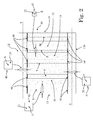
figure 2 is a schematic section view of a three-phase and five-legs inductor adapted to be used in a filter according to the present invention; -
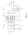
figure 3 is a schematic view, through a block diagram, of an inverter having a filter according to the present invention; -
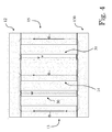
figure 4 illustrates the schematic section view offigure 2 , with arrows for schematically depicting common mode magnetic fluxes; and -
figure 5 illustrates the schematic section view offigure 2 , with arrows for schematically depicting differential mode magnetic fluxes. - It should be noted that in the detailed description that follows, identical or similar components, either from a structural and/or functional point of view, have the same reference numerals, regardless of whether they are shown in different embodiments of the present disclosure; it should also be noted that in order to clearly and concisely describe the present disclosure, the drawings may not necessarily be to scale and certain features of the disclosure may be shown in somewhat schematic form.
- Further, when the term "adapted" or "arranged" or "configured" or "shaped", is used herein while referring to any component as a whole, or to any part of a component, or to a whole combinations of components, or even to any part of a combination of components, it has to be understood that it means and encompasses correspondingly either the structure, and/or configuration and/or form and/or positioning of the related component or part thereof, or combinations of components or part thereof, such term refers to.
- Finally, the term transversal or transversally hereinafter used encompasses a direction non-parallel to the element or direction it is related to, and perpendicularity has to be considered a specific case of transverse direction.
- With reference to the attached figures, the present disclosure is related to a differential and common mode filter 1 for an
inverter 100, especially for aninverter 100 suitable for renewable energy applications, such as photovoltaic or wind applications. - For example,
figure 3 schematically illustrates aninverter 100 comprising electronic power conversion means 2 which are adapted to be controlled bycontrol means 3 for converting into an AC power a DC power received in input through a plurality of DC input connectors 4 from one or more DC sources, such as photovoltaic panels or wind towers. - For example, the electronic power conversion means 2 can comprise a first DC/
DC boosting stage 5 followed by a convertingstage 6 having one or more electronic switching devices which can be controlled by themeans 3 for converting the DC power in the AC power. - The inverter 1 comprises at least three output
conductive lines 7 leading from an output of the power conversion means 2 torespective AC connectors 8 which can be operatively connected to one or more AC grids or loads associable to the inverter 1 itself. - In practice, the three
output lines 7 are adapted to conduct AC output signals generated by the power conversion means 2 to theAC connectors 8, in such a way to deliver the generated AC power to the one or more grids or loads connected to theconnectors 8. - The
means 3 are suitable for controlling the power conversion means 2 in such a way to generate the AC outputs of theinverter 100. In particular, the generated AC outputs comprise differential mode voltages and common mode voltages to earth, and related differential mode and common mode AC currents flowing through theoutput lines 7. - The inverter 1 further comprises a
return line 9 which is suitably for providing a common current carrying return path for the three common mode currents flowing through theoutput lines 7. - For example, as illustrated in
figure 3 , thereturn line 9 is operatively connected to the threeoutput lines 7 and to a suitable connection point of the power conversion means 2, such as a connection point in DC/DC boosting stage 5. - Since the realization, functioning and control of above disclosed power conversion means 2, from an hardware and software point of view, are readily available to a person skilled in the art and not relevant for the scope and understanding of the present invention, they will not be described in particular details.
- The
inverter 100 comprises a differential mode and common mode low-pass filter 1, i.e. a filter 1 suitable for filtering in an effective way: - higher frequency components of the differential mode outputted AC signals, while keeping in output lower frequency components as required by the AC grid or load to be fed; and
- high frequency components of the common mode outputted AC signals.
- With reference to
figures 1-2 , the filter 1 comprises one three-phase inductor 10 having acore 11. Thecore 11 comprises anupper joke 12 and alower joke 130 which longitudinally extend along respective main axes X and Y. - The
core 11 comprises threelegs lower jokes first coil 17, asecond coil 18, and athird coil 19 of theinductor 10 are wound, respectively. - Each of the
coils output lines 7, in such a way that the differential mode and the common mode currents generated by the power conversion means 2 can flow through thecoils - The
core 11 further advantageously comprises at least oneunwound leg lower jokes - For example, the
core 11 illustrated infigures 2 ,4 and5 comprises twounwound legs lower jokes unwound leg core 11 for the magnetic fluxes generated by the common mode currents flowing through thecoils - Without this return path, the common mode inductance of the filter 1 would have a low value, not enough to provide an effective attenuation of the high frequency components associated to the common mode AC outputs of the
inverter 100. This is because in an inductor having only three winding legs the total magnetic flux on each winding is given by the sum of vectors of the flux generated at the winding itself and of components of the fluxes generated at the other windings. This would mean a low overall common mode magnetic flux at thewinding legs Figure 4 illustrates for example the main components of the common mode magnetic fluxes ΦCM (without considering lower components) flowing into the exemplary illustratedcore 11 and caused by the common mode currents in thecoils - With reference to such figure, each of the common mode fluxes ΦCM generated at one of the
winding legs unwound legs - In this way, the overall common mode magnetic flux at each of the
winding legs -
Figure 5 illustrates for example the main components of the differential mode magnetic fluxes ΦD (without considering lower components) flowing into the exemplary illustratedcore 11 and caused by the differential mode currents in thecoils - With reference to such
figure 5 , the differential mode magnetic fluxes ΦD generated at thelegs legs unwound legs - With reference to
figures 4 and5 and considering that the generated common mode magnetic fluxes ΦCM are several time lower than differential mode magnetic fluxes ΦD, the overall generated magnetic field in thecore 11 is distributed as follows: - the magnetic field is greater at the
legs - the magnetic field is lower at the upper and
lower jokes - the magnetic field at the
unwound legs jokes legs - The
upper joke 12 and thelower joke 13 comprise a firstmagnetic material 20. - Preferably, with reference to
figure 2 , theupper joke 12, when seen in atransversal cross section 40, i.e. a section transversal to the longitudinal axis X, and thelower joke 130, when seen in atransversal cross section 41, i.e. a section transversal to the longitudinal axis Y, are made only of the firstmagnetic material 20. - More preferably, as in the exemplary embodiment illustrated in
figures 1 and2 , the upper andlower jokes magnetic material 20. - Each of the
legs magnetic material 21. For sake of simplicity,figure 2 illustrates for example only thetransversal cross section 42 of theleg 13. - Preferably, according to the exemplary embodiment illustrated in
figures 1 and2 , each of thelegs magnetic material 21. - The first
magnetic material 20 of thejokes magnetic material 21 of thelegs - Providing the
jokes legs such materials core 11. - Indeed, the
second material 21 must have a magnetic permeability low enough to avoid magnetic saturations in thelegs - Due to the fact that a low magnetic field is present on the first
magnetic material 20, thismaterial 20 can have a higher magnetic permeability value with respect to thesecond material 21, while avoiding magnetic saturations in thejokes - A ratio of the magnetic permeability of the first
magnetic material 20 to the magnetic permeability of the secondmagnetic material 21 has preferably a value between 500 and 1500, and more preferably between 800 and 1000. - For example, the first
magnetic material 20 has a relative magnetic permeability with respect to the free space permeability comprised between 40000 and 60000, and the secondmagnetic material 21 has a relative magnetic permeability between 40 and 60. - Preferably, the at least one unwound
leg core 11 comprises a thirdmagnetic material 22. - With reference to the exemplary embodiment illustrated in
figure 2 , each of the unwoundlegs magnetic material 22. For sake of simplicity,figure 2 illustrates for example only thetransversal cross section 43 of the unwoundleg 31. Preferably, according to the exemplary embodiment illustrated infigure 2 , the provided unwoundlegs magnetic material 22. - The third
magnetic material 22 has a magnetic permeability higher than the magnetic permeability of the secondmagnetic material 21 of the windinglegs magnetic material 20 of the upper andlower jokes - Providing the unwound
legs different material 22 with respect to thematerials core 11 is particularly advantageous in view of the above disclosed distribution of the magnetic field - Indeed, since an intermediate magnetic field is present at the unwound
legs jokes legs legs - A ratio of the magnetic permeability of the third
magnetic material 22 to the magnetic permeability of the secondmagnetic material 21 has preferably a value comprised between 50 and 150, and more preferably between 80 and 100. - For example, the third
magnetic material 22 has a relative magnetic permeability with respect to the free space permeability comprised between 4000 and 6000. - Preferably, the magnetic reluctance of the one or more
unwound legs core 11 is lower than the magnetic reluctance of the windinglegs - Preferably, the one or more
unwound legs legs figure 2 , the thickness of the two unwoundlegs legs - The cross section surface of the unwound
legs other legs legs legs - According to the exemplary embodiment illustrated in
figures 1 and2 , thelegs leg 14 is an inner leg which is disposed between theouter legs - Preferably, the at least one unwound
leg unwound leg 30 which is disposed between theouter leg 13 and theinner leg 14. More preferably, in the case that thecore 11 comprises a secondunwound leg 31, thissecond leg 31 is disposed between theouter leg 15 and theinner leg 14 as illustrated in the exemplary embodiment offigure 2 . - This is particularly advantageous in view of the manufacturing process of the inductor 1; indeed, firstly the
coils legs core 11 is compacted. - During this compacting operation, the unwound
legs legs legs - the
leg 30 is sandwiched between thecoils inner legs - the
leg 31 is sandwiched between thecoils outer legs inductor 10 advantageously comprises at least one air gap for increasing the saturation threshold of thecore 11. - According to an exemplary embodiment, the winding
legs magnetic material 21 which are stacked to each other and which are separated from each other by air gaps. - For example, the magnetic blocks can be stacked to each other using lays of adhesive material, such as glue. The lays of adhesive materials are advantageously air gaps between the stacked blocks.
- In addition or alternatively to this solution, the inductor 1 can comprise an
air gap 50 between at least one of thecore legs lower jokes figure 2 , the inductor 1 comprisesair gaps 50 between each of thelegs lower jokes - With reference to
figure 3 , the filter 1 preferably comprises, in addition to the three-phase inductor 1, threecapacitors 60, each one operatively connected with a corresponding one of thecoils 17. 18. 10 of theinductor 10; infigure 3 , the threecapacitors 60 are for example connected to each other in a star connection. Thereturn line 9 starts at thestar connection point 61 between thecapacitors 60. - In practice, it has been seen how the filter 1 comprising the three-
phase inductor 10 allows achieving the intended object offering some improvements over known solutions. - In particular, due to the presence of at least one unwound
leg inductor 10 can provide a common mode inductance LCOM having a value high enough to guarantee an effective common mode filtering capability for the filter 1, in addition to an effective differential mode filtering capability. This solution is cheaper and less cumbersome than providing three single-phase inductors, each one for acorresponding output line 7 of theinverter 100. - The differential and common mode filtering capabilities of the
filter 10 are further increased by suitably usingmaterials - In particular, the fact of having the first
magnetic material 20 of the upper andlower jokes magnetic material 21 of the windinglegs lower jokes - According to the exemplary above disclosed embodiment, the value of the common and differential mode inductances LCOM, LD can be further increased by using the third
magnetic material 22 for the one or moreunwound legs material 22 is lower than the magnetic permeability of the firstmagnetic material 20, in order to avoid saturation at the unwoundlegs magnetic material 21 used for the windinglegs related inverter 100, are also susceptible of modifications and variations, all of which are within the scope of the inventive concept as defined in particular by the appended claims. - For example, even if in the exemplary embodiment illustrated in the attached figures the core 11 comprises two unwound
legs core 11 of an inductor 1 according to the present invention can have only one or more than two unwound legs. - For example, even if in the exemplary embodiment illustrated in the attached figures the inductor 1 comprises
air gaps 50 between each one of the wound and unwoundlegs lower jokes air gaps 50 only between some of the wound and unwoundlegs lower jokes
Claims (15)
- A differential and common mode filter (1) for an inverter (100), comprising an inductor (10) having a core (11) and characterized in that said core comprises:- an upper joke (12) and a lower joke (130) which comprise a first magnetic material (20);- a first leg (13), a second leg (14) and a third leg (15) which extend between said upper and lower jokes and around which a first coil (17), a second coil (18), and a third coil (19) are arranged, respectively, wherein at least one portion of said first, second and third legs, when seen in a transverse cross section (42), is made of one second magnetic material (21), and wherein said first magnetic material has a magnetic permeability higher than the magnetic permeability of the second magnetic material;- at least one unwound leg (30, 31) extending between said upper and lower jokes.
- The filter (1) according to claim 1, wherein said at least one unwound leg (30, 31) comprises a third magnetic material (22) having a magnetic permeability higher than the magnetic permeability of the second magnetic material (21) and lower that the magnetic permeability of the first magnetic material (20).
- The filter (1) according to claim 1 or claim 2, wherein said first and third legs (13, 15) are outer legs of the core (11), said second leg (14) is an inner leg disposed between said first and third outer legs (13, 15), and said at least one unwound leg (30, 31) comprises at least a first unwound leg (30) disposed between said first outer leg (13) and said second inner leg (14).
- The filter (1) according to claim 3, wherein said at least one unwound leg (30, 31) comprises a second unwound leg (31) disposed between said second inner leg (14) and said outer third leg (15).
- The filter (1) according to one or more of the preceding claims, wherein said at least one unwound leg (30, 31) has a transversal cross section (43) having a surface lower than the surface of the transversal cross section (42) of said first, second and third legs (13, 14, 15).
- The filter (1) according to one or more of the preceding claims, wherein said at least one unwound leg (30, 31) has a magnetic reluctance lower than the magnetic reluctance of said first, second and third legs (13, 14, 15).
- The filter (1) according to one or more of the preceding claims, wherein said inductor (10) comprises at least one air gap (50).
- The filter (1) according to claim 7, wherein at least one of said first, second and third legs (13, 14, 15) comprises a stack of blocks made by said second magnetic material (21) and separated from each other by air gaps.
- The filter (1) according to claim 8, wherein said blocks are stacked to each other by lays of adhesive material.
- The filter (1) according to one or more of claims 7-9, wherein said inductor (10) comprises an air gap (50) between at least one of said first, second, third and unwound legs (13, 14, 15, 30, 31) and at least one of said upper and lower jokes (12, 130).
- The filter (1) according to one or more of the preceding claims, wherein a ratio of the magnetic permeability of the first magnetic material (20) to the magnetic permeability of the second magnetic material (21) has a value comprised between 500 and 1500.
- The filter (1) according to one or more of claims 2-11, wherein a ratio of the magnetic permeability of said third magnetic material (22) to the magnetic permeability of the second magnetic material (21) has a value comprised between 50 and 150.
- The filter (1) according to one or more of the preceding claims, comprising three capacitors (60), each of said three capacitors being connected with a corresponding one of said first, second and third coils (13, 14, 15).
- An inverter (100), characterized in that it comprises a filter (1) according to one or more of the preceding claims 1-13.
- A renewable energy generation system characterized in that it comprises at least one inverter (100) according to claim 14.
Priority Applications (2)
| Application Number | Priority Date | Filing Date | Title |
|---|---|---|---|
| EP15174829.0A EP3113196B1 (en) | 2015-07-01 | 2015-07-01 | Common mode and differential mode filter for an inverter and inverter comprising such filter |
| US15/195,376 US10381916B2 (en) | 2015-07-01 | 2016-06-28 | Common mode and differential mode filter for an inverter and inverter comprising such filter |
Applications Claiming Priority (1)
| Application Number | Priority Date | Filing Date | Title |
|---|---|---|---|
| EP15174829.0A EP3113196B1 (en) | 2015-07-01 | 2015-07-01 | Common mode and differential mode filter for an inverter and inverter comprising such filter |
Publications (2)
| Publication Number | Publication Date |
|---|---|
| EP3113196A1 true EP3113196A1 (en) | 2017-01-04 |
| EP3113196B1 EP3113196B1 (en) | 2020-10-28 |
Family
ID=53525076
Family Applications (1)
| Application Number | Title | Priority Date | Filing Date |
|---|---|---|---|
| EP15174829.0A Not-in-force EP3113196B1 (en) | 2015-07-01 | 2015-07-01 | Common mode and differential mode filter for an inverter and inverter comprising such filter |
Country Status (2)
| Country | Link |
|---|---|
| US (1) | US10381916B2 (en) |
| EP (1) | EP3113196B1 (en) |
Cited By (2)
| Publication number | Priority date | Publication date | Assignee | Title |
|---|---|---|---|---|
| CN115312304A (en) * | 2022-07-13 | 2022-11-08 | 华为数字能源技术有限公司 | Integrated inductors, board assemblies and inverters |
| WO2026021845A1 (en) * | 2024-07-25 | 2026-01-29 | Tdk Electronics Ag | Inductive component |
Families Citing this family (2)
| Publication number | Priority date | Publication date | Assignee | Title |
|---|---|---|---|---|
| JP6684451B2 (en) * | 2017-02-15 | 2020-04-22 | 株式会社オートネットワーク技術研究所 | Reactor |
| CN110310801A (en) * | 2019-07-19 | 2019-10-08 | 东莞市大忠电子有限公司 | 5G integrated three-phase common mode inductor |
Citations (5)
| Publication number | Priority date | Publication date | Assignee | Title |
|---|---|---|---|---|
| DE3305708A1 (en) * | 1983-02-18 | 1984-08-23 | Transformatoren Union Ag, 7000 Stuttgart | THREE-PHASE THROTTLE COIL WITH FIFTH LEG CORE |
| JP2007048897A (en) * | 2005-08-09 | 2007-02-22 | Mitsubishi Electric Corp | Noise filter |
| US20080174255A1 (en) * | 2007-01-22 | 2008-07-24 | Johnson Controls Technology Company | Common mode & differential mode filter for variable speed drive |
| EP2453450A1 (en) * | 2010-11-12 | 2012-05-16 | Falco Electronics Ltd. | Hybrid core for power inductor |
| US20150123479A1 (en) * | 2012-08-28 | 2015-05-07 | Hitachi, Ltd. | Power conversion apparatus |
Family Cites Families (6)
| Publication number | Priority date | Publication date | Assignee | Title |
|---|---|---|---|---|
| JPS58148946A (en) | 1982-02-27 | 1983-09-05 | Nissan Motor Co Ltd | Detector for air fuel ratio |
| US7889026B2 (en) * | 2008-01-08 | 2011-02-15 | Harris Corporation | Electronically variable inductor, associated tunable filter and methods |
| WO2009114873A1 (en) * | 2008-03-14 | 2009-09-17 | Volterra Semiconductor Corporation | Voltage converter inductor having a nonlinear inductance value |
| US9019062B2 (en) * | 2010-12-08 | 2015-04-28 | Epcos Ag | Inductive device with improved core properties |
| KR101241564B1 (en) * | 2011-08-04 | 2013-03-11 | 전주대학교 산학협력단 | Couple inductor, Couple transformer and Couple inductor-transformer |
| TWI539473B (en) * | 2012-08-21 | 2016-06-21 | 乾坤科技股份有限公司 | Variable coupled inductor |
-
2015
- 2015-07-01 EP EP15174829.0A patent/EP3113196B1/en not_active Not-in-force
-
2016
- 2016-06-28 US US15/195,376 patent/US10381916B2/en not_active Expired - Fee Related
Patent Citations (5)
| Publication number | Priority date | Publication date | Assignee | Title |
|---|---|---|---|---|
| DE3305708A1 (en) * | 1983-02-18 | 1984-08-23 | Transformatoren Union Ag, 7000 Stuttgart | THREE-PHASE THROTTLE COIL WITH FIFTH LEG CORE |
| JP2007048897A (en) * | 2005-08-09 | 2007-02-22 | Mitsubishi Electric Corp | Noise filter |
| US20080174255A1 (en) * | 2007-01-22 | 2008-07-24 | Johnson Controls Technology Company | Common mode & differential mode filter for variable speed drive |
| EP2453450A1 (en) * | 2010-11-12 | 2012-05-16 | Falco Electronics Ltd. | Hybrid core for power inductor |
| US20150123479A1 (en) * | 2012-08-28 | 2015-05-07 | Hitachi, Ltd. | Power conversion apparatus |
Cited By (2)
| Publication number | Priority date | Publication date | Assignee | Title |
|---|---|---|---|---|
| CN115312304A (en) * | 2022-07-13 | 2022-11-08 | 华为数字能源技术有限公司 | Integrated inductors, board assemblies and inverters |
| WO2026021845A1 (en) * | 2024-07-25 | 2026-01-29 | Tdk Electronics Ag | Inductive component |
Also Published As
| Publication number | Publication date |
|---|---|
| EP3113196B1 (en) | 2020-10-28 |
| US20170005566A1 (en) | 2017-01-05 |
| US10381916B2 (en) | 2019-08-13 |
Similar Documents
| Publication | Publication Date | Title |
|---|---|---|
| JP5507007B2 (en) | Integrated magnetic device for low-harmonic three-phase front-end equipment | |
| US7847535B2 (en) | Method and device for supply to a magnetic coupler | |
| US7277302B2 (en) | 12-pulse converter including a filter choke incorporated in the rectifier | |
| CN102332808B (en) | Comprise the inverter filtering device of differential mode and common mode and comprise the system of this inverter filtering device | |
| CN108140474B (en) | Inductance assembly and power supply system using same | |
| JP7036513B2 (en) | Power supply system and method | |
| KR20210076062A (en) | Polyphase converter topologies for polyphase and single-phase operation | |
| US10381916B2 (en) | Common mode and differential mode filter for an inverter and inverter comprising such filter | |
| US20170263360A1 (en) | Integral Inductor Arrangement | |
| US8988182B2 (en) | Transformers and methods for constructing transformers | |
| KR102345696B1 (en) | Reactor Integrated Transformer | |
| WO2020115360A1 (en) | Inverter design comprising a nonlinear inductor | |
| KR20220134315A (en) | Magnetically controlled reactor for supplying lagging reactive power to power system and reactive power supplying device | |
| CN108432106B (en) | power conversion system | |
| JP5492391B2 (en) | Inverter device | |
| CN104937514B (en) | Distribution transformer, distribution system and regulation or the method controlling distribution transformer | |
| HK1261876A1 (en) | An electrical power supply system and process | |
| CN104937514A (en) | Distribution transformer |
Legal Events
| Date | Code | Title | Description |
|---|---|---|---|
| PUAI | Public reference made under article 153(3) epc to a published international application that has entered the european phase |
Free format text: ORIGINAL CODE: 0009012 |
|
| STAA | Information on the status of an ep patent application or granted ep patent |
Free format text: STATUS: THE APPLICATION HAS BEEN PUBLISHED |
|
| AK | Designated contracting states |
Kind code of ref document: A1 Designated state(s): AL AT BE BG CH CY CZ DE DK EE ES FI FR GB GR HR HU IE IS IT LI LT LU LV MC MK MT NL NO PL PT RO RS SE SI SK SM TR |
|
| AX | Request for extension of the european patent |
Extension state: BA ME |
|
| RAP1 | Party data changed (applicant data changed or rights of an application transferred) |
Owner name: ABB SCHWEIZ AG |
|
| STAA | Information on the status of an ep patent application or granted ep patent |
Free format text: STATUS: REQUEST FOR EXAMINATION WAS MADE |
|
| 17P | Request for examination filed |
Effective date: 20170623 |
|
| RBV | Designated contracting states (corrected) |
Designated state(s): AL AT BE BG CH CY CZ DE DK EE ES FI FR GB GR HR HU IE IS IT LI LT LU LV MC MK MT NL NO PL PT RO RS SE SI SK SM TR |
|
| RIC1 | Information provided on ipc code assigned before grant |
Ipc: H01F 3/10 20060101AFI20200424BHEP Ipc: H02M 7/42 20060101ALI20200424BHEP Ipc: H01F 38/02 20060101ALI20200424BHEP Ipc: H01F 37/00 20060101ALI20200424BHEP Ipc: H02M 1/12 20060101ALI20200424BHEP |
|
| GRAP | Despatch of communication of intention to grant a patent |
Free format text: ORIGINAL CODE: EPIDOSNIGR1 |
|
| STAA | Information on the status of an ep patent application or granted ep patent |
Free format text: STATUS: GRANT OF PATENT IS INTENDED |
|
| INTG | Intention to grant announced |
Effective date: 20200617 |
|
| GRAS | Grant fee paid |
Free format text: ORIGINAL CODE: EPIDOSNIGR3 |
|
| GRAA | (expected) grant |
Free format text: ORIGINAL CODE: 0009210 |
|
| STAA | Information on the status of an ep patent application or granted ep patent |
Free format text: STATUS: THE PATENT HAS BEEN GRANTED |
|
| AK | Designated contracting states |
Kind code of ref document: B1 Designated state(s): AL AT BE BG CH CY CZ DE DK EE ES FI FR GB GR HR HU IE IS IT LI LT LU LV MC MK MT NL NO PL PT RO RS SE SI SK SM TR |
|
| REG | Reference to a national code |
Ref country code: GB Ref legal event code: FG4D |
|
| REG | Reference to a national code |
Ref country code: CH Ref legal event code: EP |
|
| REG | Reference to a national code |
Ref country code: AT Ref legal event code: REF Ref document number: 1329040 Country of ref document: AT Kind code of ref document: T Effective date: 20201115 |
|
| REG | Reference to a national code |
Ref country code: DE Ref legal event code: R096 Ref document number: 602015061036 Country of ref document: DE |
|
| REG | Reference to a national code |
Ref country code: IE Ref legal event code: FG4D |
|
| RAP2 | Party data changed (patent owner data changed or rights of a patent transferred) |
Owner name: ABB SCHWEIZ AG |
|
| REG | Reference to a national code |
Ref country code: AT Ref legal event code: MK05 Ref document number: 1329040 Country of ref document: AT Kind code of ref document: T Effective date: 20201028 |
|
| REG | Reference to a national code |
Ref country code: NL Ref legal event code: MP Effective date: 20201028 |
|
| PG25 | Lapsed in a contracting state [announced via postgrant information from national office to epo] |
Ref country code: NL Free format text: LAPSE BECAUSE OF FAILURE TO SUBMIT A TRANSLATION OF THE DESCRIPTION OR TO PAY THE FEE WITHIN THE PRESCRIBED TIME-LIMIT Effective date: 20201028 Ref country code: NO Free format text: LAPSE BECAUSE OF FAILURE TO SUBMIT A TRANSLATION OF THE DESCRIPTION OR TO PAY THE FEE WITHIN THE PRESCRIBED TIME-LIMIT Effective date: 20210128 Ref country code: PT Free format text: LAPSE BECAUSE OF FAILURE TO SUBMIT A TRANSLATION OF THE DESCRIPTION OR TO PAY THE FEE WITHIN THE PRESCRIBED TIME-LIMIT Effective date: 20210301 Ref country code: RS Free format text: LAPSE BECAUSE OF FAILURE TO SUBMIT A TRANSLATION OF THE DESCRIPTION OR TO PAY THE FEE WITHIN THE PRESCRIBED TIME-LIMIT Effective date: 20201028 Ref country code: FI Free format text: LAPSE BECAUSE OF FAILURE TO SUBMIT A TRANSLATION OF THE DESCRIPTION OR TO PAY THE FEE WITHIN THE PRESCRIBED TIME-LIMIT Effective date: 20201028 Ref country code: GR Free format text: LAPSE BECAUSE OF FAILURE TO SUBMIT A TRANSLATION OF THE DESCRIPTION OR TO PAY THE FEE WITHIN THE PRESCRIBED TIME-LIMIT Effective date: 20210129 |
|
| REG | Reference to a national code |
Ref country code: LT Ref legal event code: MG4D |
|
| PG25 | Lapsed in a contracting state [announced via postgrant information from national office to epo] |
Ref country code: ES Free format text: LAPSE BECAUSE OF FAILURE TO SUBMIT A TRANSLATION OF THE DESCRIPTION OR TO PAY THE FEE WITHIN THE PRESCRIBED TIME-LIMIT Effective date: 20201028 Ref country code: AT Free format text: LAPSE BECAUSE OF FAILURE TO SUBMIT A TRANSLATION OF THE DESCRIPTION OR TO PAY THE FEE WITHIN THE PRESCRIBED TIME-LIMIT Effective date: 20201028 Ref country code: BG Free format text: LAPSE BECAUSE OF FAILURE TO SUBMIT A TRANSLATION OF THE DESCRIPTION OR TO PAY THE FEE WITHIN THE PRESCRIBED TIME-LIMIT Effective date: 20210128 Ref country code: PL Free format text: LAPSE BECAUSE OF FAILURE TO SUBMIT A TRANSLATION OF THE DESCRIPTION OR TO PAY THE FEE WITHIN THE PRESCRIBED TIME-LIMIT Effective date: 20201028 Ref country code: IS Free format text: LAPSE BECAUSE OF FAILURE TO SUBMIT A TRANSLATION OF THE DESCRIPTION OR TO PAY THE FEE WITHIN THE PRESCRIBED TIME-LIMIT Effective date: 20210228 Ref country code: LV Free format text: LAPSE BECAUSE OF FAILURE TO SUBMIT A TRANSLATION OF THE DESCRIPTION OR TO PAY THE FEE WITHIN THE PRESCRIBED TIME-LIMIT Effective date: 20201028 Ref country code: SE Free format text: LAPSE BECAUSE OF FAILURE TO SUBMIT A TRANSLATION OF THE DESCRIPTION OR TO PAY THE FEE WITHIN THE PRESCRIBED TIME-LIMIT Effective date: 20201028 |
|
| PG25 | Lapsed in a contracting state [announced via postgrant information from national office to epo] |
Ref country code: HR Free format text: LAPSE BECAUSE OF FAILURE TO SUBMIT A TRANSLATION OF THE DESCRIPTION OR TO PAY THE FEE WITHIN THE PRESCRIBED TIME-LIMIT Effective date: 20201028 |
|
| REG | Reference to a national code |
Ref country code: DE Ref legal event code: R097 Ref document number: 602015061036 Country of ref document: DE |
|
| PG25 | Lapsed in a contracting state [announced via postgrant information from national office to epo] |
Ref country code: SM Free format text: LAPSE BECAUSE OF FAILURE TO SUBMIT A TRANSLATION OF THE DESCRIPTION OR TO PAY THE FEE WITHIN THE PRESCRIBED TIME-LIMIT Effective date: 20201028 Ref country code: CZ Free format text: LAPSE BECAUSE OF FAILURE TO SUBMIT A TRANSLATION OF THE DESCRIPTION OR TO PAY THE FEE WITHIN THE PRESCRIBED TIME-LIMIT Effective date: 20201028 Ref country code: EE Free format text: LAPSE BECAUSE OF FAILURE TO SUBMIT A TRANSLATION OF THE DESCRIPTION OR TO PAY THE FEE WITHIN THE PRESCRIBED TIME-LIMIT Effective date: 20201028 Ref country code: LT Free format text: LAPSE BECAUSE OF FAILURE TO SUBMIT A TRANSLATION OF THE DESCRIPTION OR TO PAY THE FEE WITHIN THE PRESCRIBED TIME-LIMIT Effective date: 20201028 Ref country code: RO Free format text: LAPSE BECAUSE OF FAILURE TO SUBMIT A TRANSLATION OF THE DESCRIPTION OR TO PAY THE FEE WITHIN THE PRESCRIBED TIME-LIMIT Effective date: 20201028 Ref country code: SK Free format text: LAPSE BECAUSE OF FAILURE TO SUBMIT A TRANSLATION OF THE DESCRIPTION OR TO PAY THE FEE WITHIN THE PRESCRIBED TIME-LIMIT Effective date: 20201028 |
|
| PG25 | Lapsed in a contracting state [announced via postgrant information from national office to epo] |
Ref country code: DK Free format text: LAPSE BECAUSE OF FAILURE TO SUBMIT A TRANSLATION OF THE DESCRIPTION OR TO PAY THE FEE WITHIN THE PRESCRIBED TIME-LIMIT Effective date: 20201028 |
|
| PLBE | No opposition filed within time limit |
Free format text: ORIGINAL CODE: 0009261 |
|
| STAA | Information on the status of an ep patent application or granted ep patent |
Free format text: STATUS: NO OPPOSITION FILED WITHIN TIME LIMIT |
|
| 26N | No opposition filed |
Effective date: 20210729 |
|
| PG25 | Lapsed in a contracting state [announced via postgrant information from national office to epo] |
Ref country code: AL Free format text: LAPSE BECAUSE OF FAILURE TO SUBMIT A TRANSLATION OF THE DESCRIPTION OR TO PAY THE FEE WITHIN THE PRESCRIBED TIME-LIMIT Effective date: 20201028 |
|
| PGFP | Annual fee paid to national office [announced via postgrant information from national office to epo] |
Ref country code: IT Payment date: 20210727 Year of fee payment: 7 |
|
| PG25 | Lapsed in a contracting state [announced via postgrant information from national office to epo] |
Ref country code: SI Free format text: LAPSE BECAUSE OF FAILURE TO SUBMIT A TRANSLATION OF THE DESCRIPTION OR TO PAY THE FEE WITHIN THE PRESCRIBED TIME-LIMIT Effective date: 20201028 |
|
| PGFP | Annual fee paid to national office [announced via postgrant information from national office to epo] |
Ref country code: DE Payment date: 20210721 Year of fee payment: 7 |
|
| REG | Reference to a national code |
Ref country code: CH Ref legal event code: PL |
|
| GBPC | Gb: european patent ceased through non-payment of renewal fee |
Effective date: 20210701 |
|
| PG25 | Lapsed in a contracting state [announced via postgrant information from national office to epo] |
Ref country code: MC Free format text: LAPSE BECAUSE OF FAILURE TO SUBMIT A TRANSLATION OF THE DESCRIPTION OR TO PAY THE FEE WITHIN THE PRESCRIBED TIME-LIMIT Effective date: 20201028 |
|
| REG | Reference to a national code |
Ref country code: BE Ref legal event code: MM Effective date: 20210731 |
|
| PG25 | Lapsed in a contracting state [announced via postgrant information from national office to epo] |
Ref country code: LI Free format text: LAPSE BECAUSE OF NON-PAYMENT OF DUE FEES Effective date: 20210731 Ref country code: GB Free format text: LAPSE BECAUSE OF NON-PAYMENT OF DUE FEES Effective date: 20210701 Ref country code: CH Free format text: LAPSE BECAUSE OF NON-PAYMENT OF DUE FEES Effective date: 20210731 |
|
| PG25 | Lapsed in a contracting state [announced via postgrant information from national office to epo] |
Ref country code: IS Free format text: LAPSE BECAUSE OF FAILURE TO SUBMIT A TRANSLATION OF THE DESCRIPTION OR TO PAY THE FEE WITHIN THE PRESCRIBED TIME-LIMIT Effective date: 20210228 Ref country code: LU Free format text: LAPSE BECAUSE OF NON-PAYMENT OF DUE FEES Effective date: 20210701 Ref country code: FR Free format text: LAPSE BECAUSE OF NON-PAYMENT OF DUE FEES Effective date: 20210731 |
|
| PG25 | Lapsed in a contracting state [announced via postgrant information from national office to epo] |
Ref country code: IE Free format text: LAPSE BECAUSE OF NON-PAYMENT OF DUE FEES Effective date: 20210701 Ref country code: BE Free format text: LAPSE BECAUSE OF NON-PAYMENT OF DUE FEES Effective date: 20210731 |
|
| REG | Reference to a national code |
Ref country code: DE Ref legal event code: R119 Ref document number: 602015061036 Country of ref document: DE |
|
| PG25 | Lapsed in a contracting state [announced via postgrant information from national office to epo] |
Ref country code: HU Free format text: LAPSE BECAUSE OF FAILURE TO SUBMIT A TRANSLATION OF THE DESCRIPTION OR TO PAY THE FEE WITHIN THE PRESCRIBED TIME-LIMIT; INVALID AB INITIO Effective date: 20150701 Ref country code: DE Free format text: LAPSE BECAUSE OF NON-PAYMENT OF DUE FEES Effective date: 20230201 |
|
| PG25 | Lapsed in a contracting state [announced via postgrant information from national office to epo] |
Ref country code: CY Free format text: LAPSE BECAUSE OF FAILURE TO SUBMIT A TRANSLATION OF THE DESCRIPTION OR TO PAY THE FEE WITHIN THE PRESCRIBED TIME-LIMIT Effective date: 20201028 |
|
| PG25 | Lapsed in a contracting state [announced via postgrant information from national office to epo] |
Ref country code: IT Free format text: LAPSE BECAUSE OF NON-PAYMENT OF DUE FEES Effective date: 20220701 |
|
| PG25 | Lapsed in a contracting state [announced via postgrant information from national office to epo] |
Ref country code: MK Free format text: LAPSE BECAUSE OF FAILURE TO SUBMIT A TRANSLATION OF THE DESCRIPTION OR TO PAY THE FEE WITHIN THE PRESCRIBED TIME-LIMIT Effective date: 20201028 |
|
| PG25 | Lapsed in a contracting state [announced via postgrant information from national office to epo] |
Ref country code: TR Free format text: LAPSE BECAUSE OF FAILURE TO SUBMIT A TRANSLATION OF THE DESCRIPTION OR TO PAY THE FEE WITHIN THE PRESCRIBED TIME-LIMIT Effective date: 20201028 |
|
| PG25 | Lapsed in a contracting state [announced via postgrant information from national office to epo] |
Ref country code: MT Free format text: LAPSE BECAUSE OF FAILURE TO SUBMIT A TRANSLATION OF THE DESCRIPTION OR TO PAY THE FEE WITHIN THE PRESCRIBED TIME-LIMIT Effective date: 20201028 |