EP3113146A1 - Local location computation device and local location computation method - Google Patents
Local location computation device and local location computation method Download PDFInfo
- Publication number
- EP3113146A1 EP3113146A1 EP14882984.9A EP14882984A EP3113146A1 EP 3113146 A1 EP3113146 A1 EP 3113146A1 EP 14882984 A EP14882984 A EP 14882984A EP 3113146 A1 EP3113146 A1 EP 3113146A1
- Authority
- EP
- European Patent Office
- Prior art keywords
- vehicle
- road surface
- attitude angle
- self
- change
- Prior art date
- Legal status (The legal status is an assumption and is not a legal conclusion. Google has not performed a legal analysis and makes no representation as to the accuracy of the status listed.)
- Granted
Links
Images


Classifications
-
- G—PHYSICS
- G01—MEASURING; TESTING
- G01C—MEASURING DISTANCES, LEVELS OR BEARINGS; SURVEYING; NAVIGATION; GYROSCOPIC INSTRUMENTS; PHOTOGRAMMETRY OR VIDEOGRAMMETRY
- G01C21/00—Navigation; Navigational instruments not provided for in groups G01C1/00 - G01C19/00
- G01C21/26—Navigation; Navigational instruments not provided for in groups G01C1/00 - G01C19/00 specially adapted for navigation in a road network
- G01C21/28—Navigation; Navigational instruments not provided for in groups G01C1/00 - G01C19/00 specially adapted for navigation in a road network with correlation of data from several navigational instruments
-
- G—PHYSICS
- G06—COMPUTING; CALCULATING OR COUNTING
- G06T—IMAGE DATA PROCESSING OR GENERATION, IN GENERAL
- G06T7/00—Image analysis
- G06T7/70—Determining position or orientation of objects or cameras
- G06T7/73—Determining position or orientation of objects or cameras using feature-based methods
-
- G—PHYSICS
- G06—COMPUTING; CALCULATING OR COUNTING
- G06V—IMAGE OR VIDEO RECOGNITION OR UNDERSTANDING
- G06V20/00—Scenes; Scene-specific elements
- G06V20/50—Context or environment of the image
- G06V20/52—Surveillance or monitoring of activities, e.g. for recognising suspicious objects
-
- G—PHYSICS
- G06—COMPUTING; CALCULATING OR COUNTING
- G06V—IMAGE OR VIDEO RECOGNITION OR UNDERSTANDING
- G06V20/00—Scenes; Scene-specific elements
- G06V20/50—Context or environment of the image
- G06V20/56—Context or environment of the image exterior to a vehicle by using sensors mounted on the vehicle
- G06V20/588—Recognition of the road, e.g. of lane markings; Recognition of the vehicle driving pattern in relation to the road
-
- G—PHYSICS
- G06—COMPUTING; CALCULATING OR COUNTING
- G06T—IMAGE DATA PROCESSING OR GENERATION, IN GENERAL
- G06T2207/00—Indexing scheme for image analysis or image enhancement
- G06T2207/30—Subject of image; Context of image processing
- G06T2207/30244—Camera pose
-
- G—PHYSICS
- G08—SIGNALLING
- G08G—TRAFFIC CONTROL SYSTEMS
- G08G1/00—Traffic control systems for road vehicles
- G08G1/16—Anti-collision systems
Definitions
- the present invention relates to a self-location calculating device and a self-location calculating method.
- Patent Literature 1 A technology has been known in which: cameras installed in a vehicle capture and obtain images of surroundings of the vehicle; and an amount of movement of the vehicle is obtained based on changes in the images (see Patent Literature 1).
- Patent Literature 1 aims at obtaining the amount of movement of the vehicle accurately even if the vehicle moves slightly at slow-speed. To this end, a feature point is detected from each image; the position of the feature point is obtained; and thereby, the amount of movement of the vehicle is obtained from the direction and distance of movement (amount of movement) of the feature point.
- Patent Literature 1 Japanese Patent Application Publication No. 2008-175717
- the foregoing conventional technology has a problem that when the road surface around the vehicle is uneven or bumpy, the technology cannot calculate the position of the vehicle accurately.
- An object of the present invention is to provide a self-location calculating device and a self-location calculating method which are capable of accurately calculating the self-location of the vehicle even in a case where the road surface around the vehicle is uneven or bumpy.
- the self-location calculating device of one aspect of the present invention captures and thus obtains an image of the road surface around the vehicle onto which a patterned light is projected, and calculates an attitude angle of the vehicle relative to the road surface from a position of the patterned light on the image. Furthermore, the self-location calculating device calculates an amount of change in the attitude of the vehicle based on temporal changes in multiple feature points on the road surface in the obtained image, and calculates a current position and a current attitude angle of the vehicle by adding the amount of change in the attitude to an initial position and the attitude angle of the vehicle.
- the self-location calculating device calculates the current position and the current attitude angle of the vehicle by adding the amount of change in the attitude to the current position and the current attitude angle of the vehicle which are calculated in the previous information process cycle.
- the self-location calculating device includes a light projector 11, a camera 12 and an engine control unit (ECU) 13.
- the light projector 11 is installed in a vehicle, and projects a patterned light onto a road surface around the vehicle.
- the camera 12 is installed in the vehicle, and is an example of an image capturing unit configured to capture and thus obtain images of the road surface around the vehicle, inclusive of an area onto which the patterned light is projected.
- the ECU 13 is an example of a control unit configured to control the light projector 11, and to perform a series of information process cycles for calculating the self-location of the vehicle from images obtained by the camera 12.
- the camera 12 is a digital camera using a solid-state image sensor such as a CCD and a CMOS, and obtains digital images which are capable of image processing. What the camera 12 captures is the road surface around the vehicle.
- the road surface around the vehicle includes road surfaces in front of, in the back of, at sides of, and beneath the vehicle.
- the camera 12 may be installed in a front section of the vehicle 10, more specifically above a front bumper, for example.
- the height at and direction in which the camera 12 is set are adjusted in a way that enables the camera 12 to capture images of feature points (textures) on the road surface 31 in front of the vehicle 10 and the patterned light 32b projected from the light projector 11.
- the focus and diaphragm of the lens of the camera 12 are automatically adjusted as well.
- the camera 12 repeatedly captures images at predetermined time intervals, and thereby obtains a series of image (frame) groups. Each time the camera 12 captures an image, image data obtained with the camera 12 is transferred to the ECU 13, and is stored in a memory included in the ECU 13.
- the light projector 11 projects the patterned light 32b having a predetermined shape, inclusive of a square or rectangular lattice image, onto the road surface 31 within an image capturing range of the camera 12.
- the camera 12 captures images of the patterned light projected onto the road surface 31.
- the light projector 11 includes a laser pointer and a diffraction grating, for example.
- the diffraction grating diffracts the laser beam projected from the laser pointer.
- the light projector 11 generates the patterned light (32b, 32a) which includes multiple spotlights arranged in a lattice image or matrix pattern.
- the light projector 11 generates the patterned light 32a including 5 ⁇ 7 spotlights.
- the ECU 13 includes a CPU, a memory, and a microcontroller including an input-output section. By executing pre-installed computer programs, the ECU 13 forms multiple information processors which function as the self-location calculating device. For each image (frame), the ECU 13 repeatedly performs the series of information process cycles for calculating the self-location of the vehicle from images obtained with the camera 12. Incidentally, the ECU 13 may be also used as an ECU for controlling other systems of the vehicle 10.
- the multiple information processors include a patterned light extraction unit 21, an attitude angle calculation unit 22, a feature point detection unit 23, an attitude change amount calculation unit 24, a self-location calculation unit 26, a patterned light control unit 27 and a road surface condition determination unit 30.
- the attitude change amount calculation unit 24 includes the feature point detection unit 23.
- the patterned light extraction unit 21 reads an image obtained by the camera 12 from the memory, and extracts the position of the patterned light from this image. For example, as shown in Fig. 3(a) , the light projector 11 projects the patterned light 32a, which includes the multiple spotlights arranged in a matrix pattern, onto the road surface 31, while the camera 12 detects the patterned light 32a reflected off the road surface 31.
- the patterned light extraction unit 21 applies a binarization process to the image obtained by the camera 12, and thereby extracts only an image of the spotlights Sp, as shown in Figs. 4(a) and 4(b) . Thereafter, as shown in Fig.
- the patterned light extraction unit 21 extracts the position of the patterned light 32a by calculating the center-of-gravity position He of each spotlight Sp, that is to say, the coordinates (Uj, Vj) of each spotlight Sp on the image.
- the coordinates are expressed using the number assigned to a corresponding pixel in the image sensor of the camera 12.
- "j" is a natural number not less than 1 but not greater than 35.
- the memory stores the coordinates (Uj, Vj) of the spotlight Sp on the image as data which indicates the position of the patterned light 32a,
- the attitude angle calculation unit 22 reads the data on the position of the patterned light 32a from the memory, and calculates the distance and attitude angle of the vehicle 10 relative to the road surface 31 from the position of the patterned light 32a on the image obtained by the camera 12. For example, as shown in Fig. 3(a) , using the trigonometrical measurement principle, the attitude angle calculation unit 22 calculates the position of each spotlighted area on the road surface 31, as the relative position of the spotlighted area relative to the camera 12, from a base length Lb between the light projector 11 and the camera 12, as well as the coordinates (Uj, Vj) of each spotlight on the image.
- the attitude angle calculation unit 22 calculates a plane equation of the road surface 31 onto which the patterned light 32a is projected, that is to say, the distance and attitude angle (normal vector) of the camera 12 relative to the road surface 31, from the relative position of each spotlight relative to the camera 12.
- the distance and attitude angle of the camera 12 relative to the road surface 31 are calculated as an example of the distance and attitude angle of the vehicle 10 relative to the road surface 31 since the position of installation of the camera 12 in the vehicle 10 and the angle for the camera 12 to capture images are already known.
- the distance between the road surface 31 and the vehicle 10, as well as the attitude angle of the vehicle 10 relative to the road surface 31 can be obtained by calculating the distance and attitude angle of the camera 12 relative to the road surface 31.
- the attitude angle calculation unit 22 is capable of obtaining the position of each spotlighted area on the road surface 31, as the relative position (Xj, Yj, Zj) relative to the camera 12, from the coordinates (Uj, Vj) of each spotlight on the image.
- the distance and attitude angle of the camera 12 relative to the road surface 31 will be abbreviated as "distance and attitude angle.”
- the distance and attitude angle calculated by the attitude angle calculation unit 22 are stored into the memory.
- the attitude angle calculation unit 22 stops calculating the distance and attitude angle of the vehicle 10.
- the relative position (Xj, Yj, Zj) of each spotlight relative to the camera 12 is not present on the same plane. This is because the relative position of each spotlight changes according to the unevenness of the asphalt of the road surface 31. For this reason, the method of least squares may be used to obtain a plane equation which makes the sum of squares of distance error of each spotlight becomes least. Data on the thus-calculated distance and attitude angle is used by the self-location calculation unit 26 shown in Fig. 1 .
- the feature point detection unit 23 reads the image obtained by the camera 12 from the memory, and detects feature points on the road surface 31 from the image read from the memory. In order to detect the feature points on the road surface 31, the feature point detection unit 23 may use a method described in “ D. G. Lowe, “Distinctive Image Features from Scale-Invariant Keypoints," Int. J. Comput. Vis., vol. 60, no. 2, pp. 91-110, Nov. 200 .” Otherwise, the feature point detection unit 23 may use a method described in " Kanazawa Yasushi, Kanatani Kenichi, "Detection of Feature Points for Computer Vision," IEICE Journal, vol. 87, no. 12, pp. 1043-1048, Dec. 2004 .”
- the feature point detection unit 23 uses the Harris operator or the SUSAN operator, and detects points such as apexes of an object, the luminance values of which are largely different from the vicinities of the points as the feature points. Instead, however, the feature point detection unit 23 may use a SIFT (Scale-Invariant Feature Transform) feature amount so that points around which the luminance values change with certain regularity are detected as the feature points. And the feature point detection unit 23 counts the total number N of feature points detected from one image, and assigns identification numbers (i (1 ⁇ i ⁇ N)) to the respective feature points. The position (Ui, Vi) of each feature point on the image are stored in the memory inside the ECU 13. Figs. 6(a) and 6(b) each shows examples of the feature points Te which are detected from the image captured by the camera 12. Furthermore, directions of changes of each feature point Te and amounts of changes in each feature point Te are expressed with vectors Dte.
- SIFT Scale-Invariant Feature Transform
- particles of asphalt mixture with a particle size of not less than 1 cm but not greater than 2 cm are assumed as the feature points on the road surface 31.
- the camera 12 employs the VGA resolution mode (approximate 300 thousand pixels) in order to detect the feature points.
- the distance of the camera 12 relative to the road surface 31 is approximately 70 cm.
- the direction in which the camera 12 captures images is tilted at approximately 45 degrees to the road surface 31 from the horizontal plane.
- the luminance value of each image captured by the camera 12 and thereafter sent to the ECU 13 is within a range of 0 to 255 (0: darkest, 255: brightest).
- the attitude change amount calculation unit 24 reads, from the memory, the positional coordinates (Ui, Vi) of the multiple feature points on an image included in an image of previous frame (at time t) which is among the image of flames captured at each certain information process cycle. Furthermore, the attitude change amount calculation unit 24 reads, from the memory, the positional coordinates (Ui, Vi) of the multiple feature points on the image included in an image of the current frame (at time t+ ⁇ t). Thereafter, based on the temporal changes in the positions of the multiple feature points on the image, the attitude change amount calculation unit 24 obtains an amount of change in the attitude of the vehicle.
- the amount of change in the attitude of the vehicle includes both “amounts of changes in the distance and attitude angle" of the vehicle relative to the road surface and an “amount of movement of the vehicle” on the road surface. Descriptions will be hereinbelow provided for how to calculate the “amounts of changes in the distance and attitude angle” and the “amount of movement of the vehicle”.
- Fig. 6(a) shows an example of a first frame (image) 38 (in Fig. 5 ) captured at time t.
- a relative position (Xi, Yi, Zi) of each of three feature points Te1, Te2, Te3 are calculated on the first frame 38, for example.
- a plane G (see Fig. 6(a) ) identified by the feature points Te1, Te2, Te3 can be regarded as the road surface.
- the attitude change amount calculation unit 24 is capable of obtaining the distance and attitude angle (normal vector) of the camera 12 relative to the road surface (the plane G), from the relative position (Xi, Yi, Zi) of each of the feature points. Furthermore, from an already-known camera model, the attitude change amount calculation unit 24 is capable of obtaining a distance 11, 12, 13 between each feature point Te1, Te2, Te3, as well as an angle between straight lines joining each feature points Te1, Te2, Te3.
- the camera 12 in Fig. 5 shows the position of the camera when the first frame is captured.
- the three-dimensional coordinates (Xi, Yi, Zi) of the relative position of each feature point relative to the camera 12 are set in a way that: the Z-axis coincides with the direction in which the camera 12 captures the image; and the X and Y axes orthogonal to each other in a plane including the camera 12 are lines normal to the direction in which the camera 12 captures the image.
- the coordinates on the image 38 are set such that: the V-axis coincides with the horizontal direction; and the U-axis coincides with the vertical direction.
- Fig. 6(b) shows a second frame 38' obtained at time (t+ ⁇ t) where the time length ⁇ t passed from time t.
- a camera 12' in Fig. 5 shows a position of the camera when camera captures the second frame 38'.
- the camera 12' captures an image including the feature points Te1, Te2, Te3 in the second frame 38', and the feature point detection unit 23 detects the feature points Te1, Te2, Te3 from the image.
- the attitude change amount calculation unit 24 is capable of calculating an amount ⁇ L of movement of the camera 12 in the interval of time ⁇ t from: the relative position (Xi, Yi, Zi) of each of the feature points Te1, Te2, Te3 at time t; a position P1(Ui, Vi) of each feature point on the second frame 38'; and the camera model of the camera 12. Accordingly, the attitude change amount calculation unit 24 is capable of calculating the amount of movement of the vehicle. Furthermore, the attitude change amount calculation unit 24 is capable of calculating the amounts of changes in the distance and attitude angle as well.
- the attitude change amount calculation unit 24 is capable of calculating the amount ( ⁇ L) of movement of the camera 12 (the vehicle) and the amounts of changes in the distance and attitude angle of the camera 12 (the vehicle) by solving the following system of simultaneous equations (1) to (4).
- the equation (1) mentioned below is based on an ideal pinhole camera free from strain and optical axial misalignment which is modeled after the camera 12, where ⁇ i and f denote a constant and a focal length.
- the parameters of the camera model may be calibrated in advance.
- the attitude change amount calculation unit 24 may select optimum feature points based on positional relationships among the feature points.
- An example of a selection method usable for this purpose is the epipolar geometry (the epipolar line geometry described in R. I. Hartley, "A linear method for reconstruction from lines and points," Proc. 5th International Conference on Computer Vision, Cambridge, Massachusetts, pp. 882-887 (1995 )).
- the attitude change amount calculation unit 24 is capable of calculating the "amount of change in the attitude angle of the vehicle" from the relative positions (Xi, Yi, Zi) of the multiple feature points on the road surface and the temporal changes of the positions (Ui, Vi) of the feature points on the image. Furthermore, the attitude change amount calculation unit 24 is capable of calculating the amount of movement of the vehicle.
- the continuation of the process (integration operation) of adding the amounts of changes in the distance and attitude angle makes it possible to continuously update the distance and attitude angle without using the patterned light 32a.
- the distance and attitude angle calculated using the patterned light 32a, or a predetermined initial distance and initial attitude angle may be used for the first information process cycle.
- the distance and attitude angle which are starting points of the integration operation may be calculated using the patterned light 32a, or may use predetermined initial values. It is desirable that the predetermined initial distance and the predetermined initial attitude angle are a distance and an attitude angle determined with at least the occupants and payload of the vehicle 10 taken into consideration.
- the distance and attitude angle calculated using the patterned light 32a which is projected while the ignition switch of the vehicle 10 is on and when the shift position is moved from the parking position to another position may be used as the predetermined initial distance and the initial attitude angle.
- the distance and attitude angle which is not affected by the roll movement or pitch movement due to a turn, acceleration or deceleration of the vehicle 10.
- the associating of the feature points in the current frame with the feature points in the previous frame may be achieved, for example, by: storing an image of a small area around each detected feature point into the memory; and for each feature point, making a determination from a similarity in luminance and color information.
- the ECU 13 stores a 5(horizontal) ⁇ 5(vertical)-pixel image around each detected feature point into the memory. If for example, the error in the luminance information having 20 or more pixels is equal to or less than 1%, the attitude change amount calculation unit 24 determines that the feature points in question correspond between the current and previous frames. Thereafter, the amount of change in the attitude obtained through the foregoing process is used by the self-location calculation unit 26 in the next process step to calculate the self-location of the vehicle 10.
- the self-location calculation unit 26 calculates the current distance and attitude angle of the vehicle 10 from the “amounts of changes in the distance and attitude angle" calculated by the attitude change amount calculation unit 24. In addition, the self-location calculation unit 26 calculates the self-location of the vehicle 10 from the "amount of movement of the vehicle” calculated by the attitude change amount calculation unit 24.
- the self-location calculation unit 26 updates the distance and attitude angle with the most recent numerical values by sequentially adding (performing an integration operation on) the amounts of changes in the distance and attitude angle calculated for each frame by the attitude change amount calculation unit 24 to the starting points, that is to say, the distance and attitude angle calculated by the attitude angle calculation unit 22.
- the self-location calculation unit 26 calculates the self-location of the vehicle by: setting the position of the vehicle, which is obtained when the attitude angle calculation unit 22 calculates the distance and attitude angle, as the starting point (the initial position of the vehicle); and by sequentially adding (performing an integration operation on) the amount of movement of the vehicle from the initial position of the vehicle. For example, by setting the starting point (the initial position of the vehicle) which matches the position on a map, the self-location calculation unit 26 is capable of sequentially calculating the current self-location of the vehicle on the map.
- the attitude change amount calculation unit 24 is capable of calculating the self-location of the vehicle by obtaining the amount ( ⁇ L) of movement of the camera 12 for the time length ⁇ t.
- the attitude change amount calculation unit 24 is capable of calculating the amounts of changes in the distance and attitude angle at the same time.
- the attitude change amount calculation unit 24 is capable of accurately calculating the amount ( ⁇ L) of movement in six degrees of freedom (forward/rearward moving, leftward/rightward moving, upward/downward moving, yawing, pitching and rolling). In other words, an error in estimating the amount ( ⁇ L) of movement can be minimized even if the distance and attitude angle are changed by the roll movement or pitch movement due to the turn, acceleration or deceleration of the vehicle 10.
- the amount ( ⁇ L) of movement of the camera 12 is calculated by: calculating the amounts of changes in the distance and attitude angle; and updating the distance and attitude angle.
- the amount ( ⁇ L) of movement of the camera 12 may be calculated by: calculating the amount of change in only the attitude angle of the camera 12 relative to the road surface 31; and updating only the attitude angle of the camera 12. In this case, it may be supposed that the distance between the road surface 31 and the camera 12 remains constant. This makes it possible to reduce the operation load on the ECU 13 while minimizing the error in estimating the amount ( ⁇ L) of movement with the amount of change in the attitude angle taken into consideration, and to increase the operation speed of the ECU 13.
- the patterned light control unit 27 controls the projection of the patterned light 32a by the light projector 11. For example, when the ignition switch of the vehicle 10 is turned on, and the self-location calculating device becomes activated, the patterned light control unit 27 starts to project the patterned light 32a at the same time. Thereafter, until the self-location calculating device stops its operation, the patterned light control unit 27 continues projecting the patterned light 32a. Otherwise, the patterned light control unit 27 may alternately turn on and off the light projection in predetermined intervals.
- the road surface condition determination unit 30 detects changes in the conditions of the road surface around the vehicle, and determines whether or not the conditions of the road surface change as much as or more than the threshold value. If the road surface condition determination unit 30 determines that the conditions of the road surface change as much as or more than the threshold value, the self-location calculation unit 26 fixes the starting points at the current position of the vehicle 10, as well as the current distance and attitude angle of the vehicle 10 relative to the road surface, which are calculated in the previous information process cycle. Thereby, the attitude angle calculation unit 22 stops calculating the distance and attitude angle of the vehicle 10 relative to the road surface.
- the self-location calculation unit 26 calculates the current position of the vehicle in present, as well as the current distance and attitude angle of the vehicle 10 relative to the road surface, by adding the amount of change in the attitude to the current position of the vehicle 10, as well as the current distance and attitude angle of the vehicle 10 relative to the road surface, which are calculated in the previous information process cycle.
- the 35 (5 ⁇ 7) spotlights of the patterned light 32a are projected on the road surface.
- the road surface condition determination unit 30 determines that: the road surface becomes very uneven or bumpy; and the conditions of the road surface change as much as or more than the threshold value.
- the road surface condition determination unit 30 may estimate the changes in the conditions of the road surface from an amount of changes in heights of the road surface.
- the amount of changes in heights of the road surface can be detected from oscillations of a value detected by a stroke sensor attached to the suspension of each wheel of the vehicle. For example, if the oscillations of the value detected by the stroke sensor becomes equal to or greater than 1 Hz, the road surface condition determination unit 30 estimates that the road surface becomes very uneven or bumpy, and determines that the conditions of the road surface change as much as or more than the threshold value.
- the road surface condition determination unit 30 may be configured to: calculate a velocity in the vertical direction by integrating values detected by an acceleration sensor for measuring the acceleration in the vertical direction; and thereby determine that the road surface becomes very uneven or bumpy and the conditions of the road surface change as much as or more than the threshold value, when a change in the direction of the velocity becomes equal to or greater than 1 Hz.
- the amount of changes in heights of the road surface may be estimated from the position of the patterned light 32a on the image captured by the camera 12.
- the patterned light 32a as shown in Fig. 7 is projected onto the road surface 31.
- a line segment 71 joining spotlights of the patterned light 32a in an X direction, and a line segment 73 joining spotlights of the patterned light 32a in a Y direction are drawn.
- the road surface condition determination unit 30 estimates that the road surface becomes very uneven or bumpy, and determines that the conditions of the road surface change as much as or more than the threshold value.
- the road surface condition determination unit 30 may determine that the conditions of the road surface change as much as or more than the threshold value, when a difference between distances d1, d2 between adjacent spotlights changes as much as or more than 50%.
- the self-location calculation unit 26 fixes the starting points at the current position of the vehicle 10, as well as the current distance and attitude angle of the vehicle 10 relative to the road surface, which are calculated in the previous information process cycle.
- the attitude angle calculation unit 22 stops calculating the distance and attitude angle of the vehicle 10 relative to the road surface.
- the self-location calculation unit 26 calculates the current position of the vehicle 10 in present, as well as the current distance and attitude angle of the vehicle 10 in present relative to the road surface, by adding the amount of change in the attitude to the current position of the vehicle 10, as well as the current distance and attitude angle of the vehicle 10 relative to the road surface, which are calculated in the previous information process cycle.
- the road surface condition determination unit 30 monitors the number of detected spotlights, and sets the threshold value at 28 which corresponds to 80% of the 35 spotlights. In this case, while 28 or more spotlights can be detected, the road surface condition determination unit 30 sets an attitude angle calculation flag at "ON.” Thereby, the attitude angle calculation unit 22 calculates the distance and attitude angle of the vehicle 10 relative to the road surface. Meanwhile, the self-location calculation unit 26 calculates the current self-location of the vehicle by: calculating the current distance and attitude angle using the distance and attitude angle of the vehicle calculated by the attitude angle calculation unit 22; and adding (continuing the integration operation) the amount of movement of the vehicle to the current position of the vehicle 10 which is calculated in the previous information process cycle.
- the self-location calculation unit 26 switches the attitude angle calculation flag to "OFF." Thereby, the starting points are fixed at the current position of the vehicle 10, as well as the current distance and attitude angle of the vehicle 10 relative to the road surface, which are calculated in the previous information process cycle.
- the attitude angle calculation unit 22 stops calculating the distance and attitude angle of the vehicle 10.
- the self-location calculation unit 26 calculates the current position of the vehicle in present, as well as the current distance and attitude angle of the vehicle in present relative to the road surface, by adding the amount of change in the attitude to the current position of the vehicle 10, as well as the current distance and attitude angle of the vehicle 10 relative to the road surface, which are calculated in the previous information process cycle.
- the self-location calculation unit 26 calculates the current distance and attitude angle of the vehicle 10 using the distance and attitude angle of the vehicle 10 calculated by the attitude angle calculation unit 22.
- the self-location calculating device of the embodiment uses the current position of the vehicle 10, as well as the current distance and attitude angle of the vehicle 10 relative to the road surface, which are calculated in the previous information process cycle, instead of using the distance and attitude angle of the vehicle 10 calculated by the attitude angle calculation unit 22.
- the self-location calculating device of the embodiment is capable of calculating the self-location of the vehicle 10 accurately and stably.
- the information process cycle is an example of a self-location calculating method of calculating the self-location of the vehicle 10 from the image 38 obtained by the camera 12.
- the information process cycle shown in a flowchart of Fig. 9 is started at the same time as the self-location calculating device becomes activated after the ignition switch of the vehicle 10 is turned on, and is repeatedly performed until the self-location calculating device stops its operation.
- step S01 in Fig. 9 the patterned light control unit 27 controls the light projector 11 so as to project the patterned light 32a onto the road surface 31 around the vehicle.
- the patterned light 32a is continuously projected.
- the ECU 13 controls the camera 12 to obtain the image 38 by making the camera 12 shoot the road surface 31 around the vehicle, inclusive of an area onto which the patterned light 32a is projected.
- the ECU 13 stores the data on the image obtained by the camera 12 into the memory.
- the ECU 13 is capable of automatically controlling the diaphragm of the camera 12.
- the ECU 13 may be configured to perform a feedback control of the diaphragm of the camera 12 in a way that makes a value of brightness of the image becomes a median value between the maximum and minimum values in accordance with an average of the brightness of the image 38 obtained in the previous information process cycle. Otherwise, since the value of the brightness of the area onto which the patterned light 32a is projected is high, the ECU 13 may obtain an average value of the brightness from an area outside a part from which the patterned light 32a is extracted.
- the patterned light extraction unit 21 reads the image 38 obtained by the camera 12 from the memory, and extracts the position of the patterned light 32a from the image 38, as shown in Fig. 4(c) .
- the patterned light extraction unit 21 stores the coordinates (Uj, Vj) of each spotlight Sp on the image, which are calculated as the data indicating the position of the patterned light 32a, into the memory.
- step S05 the attitude angle calculation unit 22 reads the data indicating the position of the patterned light 32a from the memory, calculates the distance and attitude angle of the vehicle 10 relative to the road surface 31 from the position of the patterned light 32a, and stores the thus-calculated distance and attitude angle into the memory.
- the ECU 13 detects the feature points from the image 38, extracts the feature points which have correspondence relation between the previous and current information process cycles, and calculates the amounts of changes in the distance and attitude angle from the positions (Ui, Vi) of the respective extracted feature points on the image. In addition, the ECU 13 calculates the amount of movement of the vehicle.
- the feature point detection unit 23 reads the image 38 obtained by the camera 12 from the memory, detects the feature points on the road surface 31 from the image 38, and stores the positions (Ui, Vi) of the respective feature points on the image into the memory.
- the attitude change amount calculation unit 24 reads the positions (Ui, Vi) of the respective feature points on the image from the memory, and calculates the relative positions (Xi, Yi, Zi) of the respective feature points relative to the camera 12 from the distance and attitude angle which are calculated by the attitude angle calculation unit 22 as well as the positions (Ui, Vi) of the feature points on the image. Incidentally, the attitude change amount calculation unit 24 uses the distance and attitude angle which are set in step S09 in the previous information process cycle. Thereafter, the attitude change amount calculation unit 24 stores the relative positions (Xi, Yi, Zi) of the feature points relative to the camera 12 into the memory.
- the attitude change amount calculation unit 24 reads the positions (Ui, Vi) of the feature points on the image, and the relative positions (Xi, Yi, Zi) of the feature points calculated in step S07 in the previous information process cycle from the memory.
- the attitude change amount calculation unit 24 calculates the amounts of changes in the distance and attitude angle using: the relative positions (Xi, Yi, Zi) of the feature points which have correspondence relation between the previous and current information process cycles; and the positions (Ui, Vi) of the thus-corresponding feature points on the image.
- the attitude change amount calculation unit 24 calculates the amount of movement of the vehicle from the previous relative positions (Xi, Yi, Zi) of the feature points and the current relative positions (Xi, Yi, Zi) of the feature points, and stores the resultant amount of movement of the vehicle into the memory.
- the “amounts of changes in the distance and attitude angle" and the “amount of movement of the vehicle" which are calculated in step S07, are used for the process in step S11.
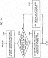
- step S09 the ECU 13 sets the starting points of the integration operation for calculating the self-location according to the changes in the conditions of the road surface around the vehicle. Details will be later described referring to Fig. 10 .
- the self-location calculation unit 26 calculates the self-location of the vehicle 10 from: the starting points of the integration operation set in step S09; and the amounts of changes in the distance and attitude angle of the vehicle 10 calculated in the process in step S07.
- the self-location calculating device of the embodiment is capable of calculating the self-location of the vehicle 10 by repeatedly performing the foregoing series of information process cycles to integrate the amount of movement of the vehicle 10.
- step S101 the road surface condition determination unit 30 detects the changes in the conditions of the road surface around the vehicle.
- the road surface condition determination unit 30 detects the number of spotlights of the patterned light 32a, or detects the oscillations of the value detected by the stroke sensor attached to each wheel.
- the road surface condition determination unit 30 may be configured to calculate the velocity in the vertical direction by integrating the values detected by the acceleration sensor capable of measuring the acceleration of the vehicle in the vertical direction, or to detect the position of the patterned light 32a.
- the road surface condition determination unit 30 determines whether or not the conditions of the road surface change as much as or more than the threshold value. For example, in a case where the road surface condition determination unit 30 is configured to detect the number of spotlights of the patterned light 32a, if only 28 or less spotlights out of the 35 spotlights can be detected on the image obtained by the camera, the road surface condition determination unit 30 determines that: the road surface becomes very uneven or bumpy; and the conditions of the road surface change as much as or more than the threshold value.
- the road surface condition determination unit 30 determines that the conditions of the road surface change as much as or more than the threshold value when the oscillations of the detected value become equal to or greater than 1 Hz. Furthermore, in a case of using the acceleration sensor, the road surface condition determination unit 30 calculates the velocity in the vertical direction by integrating the values detected by the acceleration sensor. If the changes in the direction of the velocity become equal to or greater than 1 Hz, the road surface condition determination unit 30 determines that the conditions of the road surface change as much as or more than the threshold value.
- the road surface condition determination unit 30 determines that the conditions of the road surface change as much as or more than the threshold value. Otherwise, if a difference between distances between adjacent spotlights changes as much as or more than 50%, the road surface condition determination unit 30 may determine that the conditions of the road surface change as much as or more than the threshold value.
- the road surface condition determination unit 30 determines whether or not the conditions of the road surface around the vehicle change as much as or more than the threshold value.
- the procedure proceeds to step S105.
- the road surface condition determination unit 30 determines that the conditions of the road surface around the vehicle does not change so much as or more than the threshold value (NO in step S103)
- the procedure proceeds to step S107.
- step S105 the self-location calculation unit 26 fixes the current position of the vehicle 10, as well as the current distance and attitude angle of the vehicle 10 relative to the road surface, at the current position of the vehicle 10, as well as the current distance and attitude angle of the vehicle 10 relative to the road surface, which are calculated in the previous information process cycle.
- the self-location calculation unit 26 sets the current position of the vehicle 10, as well as the current distance and attitude angle of the vehicle 10 relative to the road surface, which are calculated in the previous information process cycle, as the starting points of the integration operation.
- the attitude angle calculation unit 22 stops calculating the distance and attitude angle of the vehicle 10 relative to the road surface.
- the self-location calculation unit 26 calculates the current position of the vehicle 10 in present, as well as the current distance and attitude angle of the vehicle 10 in present relative to the road surface, by adding the amount of change in the attitude to the current position of the vehicle 10, as well as the current distance and attitude angle of the vehicle 10 relative to the road surface, which are calculated in the previous information process cycle.
- step S107 the self-location calculation unit 26 sets the starting points of the integration operation at the current position of the vehicle 10, as well as the current distance and attitude angle of the vehicle 10 relative to the road surface, which are calculated in step S05 in the current information process cycle.
- the self-location calculation unit 26 calculates the current position of the vehicle 10, as well as the current distance and attitude angle of the vehicle 10 relative to the road surface, by adding the amount of change in the attitude to the current position of the vehicle 10, as well as the current distance and attitude angle of the vehicle 10 relative to the road surface, which are calculated in the current information process cycle.
- the self-location calculation unit 26 sets the starting points of the integration operation for calculating the current position of the vehicle 10 in present, as well as the current distance and attitude angle of the vehicle 10 in present relative to the road surface, the process in step S09 is terminated, and the procedure proceeds to step S11 in Fig. 9 .
- the self-location calculating device of the embodiment calculates the current position of the vehicle in present, as well as the current distance and attitude angle of the vehicle in present relative to the road surface, by adding the amount of change in the attitude to the current position of the vehicle, as well as the current distance and attitude angle of the vehicle relative to the road surface, which are calculated in the previous information process cycle.
- the self-location calculating device of the embodiment is capable of accurately calculating the self-location of the vehicle even if the road surface around the vehicle is uneven or bumpy.
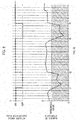
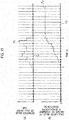
- Fig. 11 shows an example of an error in estimating a roll angle (an example of the attitude angle) of the vehicle 10, and an example of an error in estimating the amount of movement (in the vehicle-width direction) of the vehicle 10.
- Fig. 11(a) shows a temporal change in a value of the roll angle of the vehicle 10 which is calculated in a case where the vehicle 10 is running straightly which causes no roll angle
- Fig. 11(b) shows a temporal change in a value of the amount of movement of the vehicle 10 which is calculated in the same case.
- P1" and “P2" in Fig. 11 respectively represent the value in a case where the amount of movement of the vehicle is calculated using the conventional method.
- Q1" and “Q2" in Fig. 11 respectively represent the true values which are the actual value.
- the self-location calculating device of the embodiment stops calculating the current position of the vehicle 10, as well as the current distance and attitude angle of the vehicle 10 relative to the road surface, and uses, as the starting points, the current position of the vehicle 10, as well as the current distance and attitude angle of the vehicle 10 relative to the road surface, which are calculated in the previous information process cycle.
- the use of the values obtained in the previous information process cycle enables the self-location calculating device of the embodiment to prevent the errors from being amplified as indicated by P1 and P2 in Fig. 11 , and to accurately calculate the self-location of the vehicle 10.
- the self-location calculating device of the embodiment estimates the changes in the conditions of the road surface from the amount of change in the height of the road surface.
- the self-location calculating device of the embodiment is capable of securely detecting the unevenness or bumps on the road surface, and accordingly capable of accurately calculating the self-location of the vehicle.
- the self-location calculating device of the embodiment estimates the amount of change in the height of the road surface from the position of the patterned light.
- the self-location calculating device of the embodiment is capable of detecting the changes in the conditions of the road surface without using a sensor which would otherwise be installed in the vehicle, and accordingly capable of accurately calculating the self-location of the vehicle with the simple method.
- the distance and attitude angle of the vehicle 10 are calculated in each information process cycle. This embodiment is different from the first embodiment in that the distance and attitude angle of the vehicle 10 are calculated in each constant period.
- the self-location calculating device of the embodiment is set to generate a period counting pulse in each constant period, for example, corresponding to 8 frames or the like, and sets the attitude angle calculation flag at "ON" each time generating the period counting pulse.
- the distance and attitude angle of the vehicle 10 can be calculated in each constant period.
- the self-location calculating device makes the attitude angle calculation flag to remain “OFF” instead of setting the flag at "ON.” For example, during a time between time t1 and time t2, the self-location calculating device makes the attitude angle calculation flag to remain “OFF” instead of setting the flag at "ON” while generating the period counting pulse, since the number of detected spotlights is equal to or less than the threshold value.
- the road surface condition determination unit 30 fixes the current position of the vehicle, as well as the current distance and attitude angle of the vehicle relative to the road surface, at the distance and attitude angle which are calculated in the previous information process cycle.
- the attitude angle calculation unit 22 stops calculating the current position of the vehicle, as well as the current distance and attitude angle of the vehicle relative to the road surface.
- the self-location calculation unit 26 calculates the current position of the vehicle 10 in present, as well as the current distance and attitude angle of the vehicle 10 in present relative to the road surface, by adding the amount of change in the attitude to the current position of the vehicle 10, as well as the current distance and attitude angle of the vehicle 10 relative to the road surface, which are calculated in the previous information process cycle.
- the information process cycle performed by the self-location calculating device of the embodiment is the same as that of the first embodiment shown in Fig. 9 . For this reason, detailed descriptions will be omitted.
- the embodiment is different from the first embodiment in the step of setting the starting points of the integration operation in step S09 in Fig. 9 .
- step S201 the road surface condition determination unit 30 determines whether or not the predetermined period has passed. As described using Fig. 12 , the road surface condition determination unit 30 monitors whether or not the period counting pulse is generated. When the period counting pulse is generated, the road surface condition determination unit 30 determines that the predetermined period has passed, and the procedure proceeds to step S203. On the other hand, when no period counting pulse is generated, the road surface condition determination unit 30 determines that the predetermined period has not passed, and the procedure proceeds to step S207.
- the self-location calculating device of the embodiment calculates the distance and attitude angle of the vehicle in each constant period. If determining that the conditions of the road surface around the vehicle change as much as or more than the threshold value during any constant period, the self-location calculating device calculates the current position of the vehicle in present, as well as the current distance and attitude angle of the vehicle in present relative to the road surface, by adding the amount of change in the attitude to the current position of the vehicle, as well as the current distance and attitude angle of the vehicle relative to the road surface, which are calculated in the previous information process cycle. This reduces the frequency at which the attitude angle calculation unit 22 calculates the distance and attitude angle of the vehicle. Accordingly, it is possible to reduce the operation load of the ECU 13, and to increase the operation speed of the ECU 13.
Abstract
Description
- The present invention relates to a self-location calculating device and a self-location calculating method.
- A technology has been known in which: cameras installed in a vehicle capture and obtain images of surroundings of the vehicle; and an amount of movement of the vehicle is obtained based on changes in the images (see Patent Literature 1). Patent Literature 1 aims at obtaining the amount of movement of the vehicle accurately even if the vehicle moves slightly at slow-speed. To this end, a feature point is detected from each image; the position of the feature point is obtained; and thereby, the amount of movement of the vehicle is obtained from the direction and distance of movement (amount of movement) of the feature point.
- Patent Literature 1: Japanese Patent Application Publication No.
2008-175717 - The foregoing conventional technology, however, has a problem that when the road surface around the vehicle is uneven or bumpy, the technology cannot calculate the position of the vehicle accurately.
- The present invention has been proposed with the foregoing situation taken into consideration. An object of the present invention is to provide a self-location calculating device and a self-location calculating method which are capable of accurately calculating the self-location of the vehicle even in a case where the road surface around the vehicle is uneven or bumpy.
- For the purpose of solving the foregoing problem, the self-location calculating device of one aspect of the present invention captures and thus obtains an image of the road surface around the vehicle onto which a patterned light is projected, and calculates an attitude angle of the vehicle relative to the road surface from a position of the patterned light on the image. Furthermore, the self-location calculating device calculates an amount of change in the attitude of the vehicle based on temporal changes in multiple feature points on the road surface in the obtained image, and calculates a current position and a current attitude angle of the vehicle by adding the amount of change in the attitude to an initial position and the attitude angle of the vehicle. Thereafter, when determining that conditions of the road surface around the vehicle change as much as or more than a threshold value, the self-location calculating device calculates the current position and the current attitude angle of the vehicle by adding the amount of change in the attitude to the current position and the current attitude angle of the vehicle which are calculated in the previous information process cycle.
-
- [
Fig. 1] Fig. 1 is a block diagram showing an overall configuration of a self-location calculating device of a first embodiment. - [
Fig. 2] Fig. 2 is an external view showing an example of how a light projector and a camera are installed in a vehicle. - [
Fig. 3] Fig. 3(a) is a diagram showing how a position of spotlighted areas on a road surface by using the light projector and the camera is calculated.Fig. 3(b) is a diagram showing how a direction of movement of the camera is obtained from temporal changes in a feature point which is detected outside an area onto which a patterned light is projected. - [
Fig. 4] Fig. 4 is a diagram showing an image of a patterned light which is obtained by applying a binarization process to an image obtained with the camera.Fig. 4(a) is a diagram showing the entirety of the patterned light.Fig. 4(b) is a magnified diagram showing one spotlight.Fig. 4(c) is a diagram showing a position of the center of gravity of spotlights. - [
Fig. 5] Fig. 5 is a schematic diagram for describing a method of calculating amounts of changes in a distance and attitude angle. - [
Fig. 6] Fig. 6 is a diagram showing feature points detected on the image.Fig. 6(a) is a diagram showing a first frame (image) obtained at time t.Fig. 6(b) is a diagram showing a second frame obtained at time t+Δt. - [
Fig. 7] Fig. 7 is a diagram for describing how to estimate an amount of change in a height of the road surface from a position of the patterned light. - [
Fig. 8] Fig. 8 is a time chart showing a process in which the self-location calculating device of the first embodiment makes a determination on changes in conditions of the road surface. - [
Fig. 9] Fig. 9 is a flowchart showing a procedure for a self-location calculating process to be performed by the self-location calculating device of the first embodiment. - [
Fig. 10] Fig. 10 is a flowchart showing a procedure for a detailed process in step S09 inFig. 9 to be performed by the self-location calculating device of the first embodiment. - [
Fig. 11] Fig. 11 is a diagram showing an example of an error in estimating a roll angle of the vehicle, and an example of an error in estimating an amount of movement of the vehicle. - [
Fig. 12] Fig. 12 is a time chart showing a process in which the self-location calculating device of a second embodiment makes a determination on changes in conditions of the road surface. - [
Fig. 13] Fig. 13 is a flowchart showing a procedure for a detailed process in step S09 inFig. 9 to be performed by the self-location calculating device of the second embodiment. - Referring to the drawings, descriptions will be hereinbelow provided for first and second embodiments to which the present invention is applied.
- To begin with, referring to
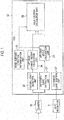
Fig. 1 , descriptions will be provided for a hardware configuration of a self-location calculating device of a first embodiment. The self-location calculating device includes alight projector 11, acamera 12 and an engine control unit (ECU) 13. Thelight projector 11 is installed in a vehicle, and projects a patterned light onto a road surface around the vehicle. Thecamera 12 is installed in the vehicle, and is an example of an image capturing unit configured to capture and thus obtain images of the road surface around the vehicle, inclusive of an area onto which the patterned light is projected. The ECU 13 is an example of a control unit configured to control thelight projector 11, and to perform a series of information process cycles for calculating the self-location of the vehicle from images obtained by thecamera 12. - The
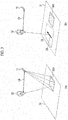
camera 12 is a digital camera using a solid-state image sensor such as a CCD and a CMOS, and obtains digital images which are capable of image processing. What thecamera 12 captures is the road surface around the vehicle. The road surface around the vehicle includes road surfaces in front of, in the back of, at sides of, and beneath the vehicle. As shown inFig. 2 , thecamera 12 may be installed in a front section of thevehicle 10, more specifically above a front bumper, for example. The height at and direction in which thecamera 12 is set are adjusted in a way that enables thecamera 12 to capture images of feature points (textures) on theroad surface 31 in front of thevehicle 10 and the patternedlight 32b projected from thelight projector 11. The focus and diaphragm of the lens of thecamera 12 are automatically adjusted as well. Thecamera 12 repeatedly captures images at predetermined time intervals, and thereby obtains a series of image (frame) groups. Each time thecamera 12 captures an image, image data obtained with thecamera 12 is transferred to theECU 13, and is stored in a memory included in theECU 13. - As shown in
Fig. 2 , thelight projector 11 projects the patternedlight 32b having a predetermined shape, inclusive of a square or rectangular lattice image, onto theroad surface 31 within an image capturing range of thecamera 12. Thecamera 12 captures images of the patterned light projected onto theroad surface 31. Thelight projector 11 includes a laser pointer and a diffraction grating, for example. The diffraction grating diffracts the laser beam projected from the laser pointer. Thereby, as shown inFigs. 2 to 4 , thelight projector 11 generates the patterned light (32b, 32a) which includes multiple spotlights arranged in a lattice image or matrix pattern. In examples shown inFigs. 3 and4 , thelight projector 11 generates the patternedlight 32a including 5×7 spotlights. - Returning to
Fig. 1 , theECU 13 includes a CPU, a memory, and a microcontroller including an input-output section. By executing pre-installed computer programs, the ECU 13 forms multiple information processors which function as the self-location calculating device. For each image (frame), theECU 13 repeatedly performs the series of information process cycles for calculating the self-location of the vehicle from images obtained with thecamera 12. Incidentally, the ECU 13 may be also used as an ECU for controlling other systems of thevehicle 10. - In this respect, the multiple information processors include a patterned
light extraction unit 21, an attitudeangle calculation unit 22, a featurepoint detection unit 23, an attitude changeamount calculation unit 24, a self-location calculation unit 26, a patternedlight control unit 27 and a road surfacecondition determination unit 30. The attitude changeamount calculation unit 24 includes the featurepoint detection unit 23. - The patterned
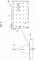
light extraction unit 21 reads an image obtained by thecamera 12 from the memory, and extracts the position of the patterned light from this image. For example, as shown inFig. 3(a) , thelight projector 11 projects the patternedlight 32a, which includes the multiple spotlights arranged in a matrix pattern, onto theroad surface 31, while thecamera 12 detects the patterned light 32a reflected off theroad surface 31. The patternedlight extraction unit 21 applies a binarization process to the image obtained by thecamera 12, and thereby extracts only an image of the spotlights Sp, as shown inFigs. 4(a) and 4(b) . Thereafter, as shown inFig. 4(c) , the patternedlight extraction unit 21 extracts the position of the patterned light 32a by calculating the center-of-gravity position He of each spotlight Sp, that is to say, the coordinates (Uj, Vj) of each spotlight Sp on the image. The coordinates are expressed using the number assigned to a corresponding pixel in the image sensor of thecamera 12. In a case where the patterned light includes 5×7 spotlights Sp, "j" is a natural number not less than 1 but not greater than 35. The memory stores the coordinates (Uj, Vj) of the spotlight Sp on the image as data which indicates the position of the patternedlight 32a, - The attitude
angle calculation unit 22 reads the data on the position of the patterned light 32a from the memory, and calculates the distance and attitude angle of thevehicle 10 relative to theroad surface 31 from the position of the patterned light 32a on the image obtained by thecamera 12. For example, as shown inFig. 3(a) , using the trigonometrical measurement principle, the attitudeangle calculation unit 22 calculates the position of each spotlighted area on theroad surface 31, as the relative position of the spotlighted area relative to thecamera 12, from a base length Lb between thelight projector 11 and thecamera 12, as well as the coordinates (Uj, Vj) of each spotlight on the image. Thereafter, the attitudeangle calculation unit 22 calculates a plane equation of theroad surface 31 onto which the patternedlight 32a is projected, that is to say, the distance and attitude angle (normal vector) of thecamera 12 relative to theroad surface 31, from the relative position of each spotlight relative to thecamera 12. - It should be noted that in the embodiment, the distance and attitude angle of the
camera 12 relative to theroad surface 31 are calculated as an example of the distance and attitude angle of thevehicle 10 relative to theroad surface 31 since the position of installation of thecamera 12 in thevehicle 10 and the angle for thecamera 12 to capture images are already known. In other words, the distance between theroad surface 31 and thevehicle 10, as well as the attitude angle of thevehicle 10 relative to theroad surface 31 can be obtained by calculating the distance and attitude angle of thecamera 12 relative to theroad surface 31. - To put it specifically, since the
camera 12 and thelight projector 11 are fixed to thevehicle 10, the direction in which the patternedlight 32a is projected and the distance (the base length Lb) between thecamera 12 and thelight projector 11 are already known. For this reason, using the trigonometrical measurement principle, the attitudeangle calculation unit 22 is capable of obtaining the position of each spotlighted area on theroad surface 31, as the relative position (Xj, Yj, Zj) relative to thecamera 12, from the coordinates (Uj, Vj) of each spotlight on the image. Hereinafter, the distance and attitude angle of thecamera 12 relative to theroad surface 31 will be abbreviated as "distance and attitude angle." The distance and attitude angle calculated by the attitudeangle calculation unit 22 are stored into the memory. - It should be noted that the descriptions are provided for the embodiment in which the distance and attitude angle are calculated in each information process cycle. Nevertheless, as mentioned below, when the road surface
condition determination unit 30 determines that conditions of the road surface change as much as or more than a threshold value, the attitudeangle calculation unit 22 stops calculating the distance and attitude angle of thevehicle 10. - Furthermore, in many cases, the relative position (Xj, Yj, Zj) of each spotlight relative to the
camera 12 is not present on the same plane. This is because the relative position of each spotlight changes according to the unevenness of the asphalt of theroad surface 31. For this reason, the method of least squares may be used to obtain a plane equation which makes the sum of squares of distance error of each spotlight becomes least. Data on the thus-calculated distance and attitude angle is used by the self-location calculation unit 26 shown inFig. 1 . - The feature
point detection unit 23 reads the image obtained by thecamera 12 from the memory, and detects feature points on theroad surface 31 from the image read from the memory. In order to detect the feature points on theroad surface 31, the featurepoint detection unit 23 may use a method described in "D. G. Lowe, "Distinctive Image Features from Scale-Invariant Keypoints," Int. J. Comput. Vis., vol. 60, no. 2, pp. 91-110, Nov. 200." Otherwise, the featurepoint detection unit 23 may use a method described in "Kanazawa Yasushi, Kanatani Kenichi, "Detection of Feature Points for Computer Vision," IEICE Journal, vol. 87, no. 12, pp. 1043-1048, Dec. 2004." - To put it specifically, for example, the feature
point detection unit 23 uses the Harris operator or the SUSAN operator, and detects points such as apexes of an object, the luminance values of which are largely different from the vicinities of the points as the feature points. Instead, however, the featurepoint detection unit 23 may use a SIFT (Scale-Invariant Feature Transform) feature amount so that points around which the luminance values change with certain regularity are detected as the feature points. And the featurepoint detection unit 23 counts the total number N of feature points detected from one image, and assigns identification numbers (i (1≤i≤N)) to the respective feature points. The position (Ui, Vi) of each feature point on the image are stored in the memory inside theECU 13.Figs. 6(a) and 6(b) each shows examples of the feature points Te which are detected from the image captured by thecamera 12. Furthermore, directions of changes of each feature point Te and amounts of changes in each feature point Te are expressed with vectors Dte. - It should be noted that in the embodiment, particles of asphalt mixture with a particle size of not less than 1 cm but not greater than 2 cm are assumed as the feature points on the
road surface 31. Thecamera 12 employs the VGA resolution mode (approximate 300 thousand pixels) in order to detect the feature points. In addition, the distance of thecamera 12 relative to theroad surface 31 is approximately 70 cm. Moreover, the direction in which thecamera 12 captures images is tilted at approximately 45 degrees to theroad surface 31 from the horizontal plane. What is more, the luminance value of each image captured by thecamera 12 and thereafter sent to theECU 13 is within a range of 0 to 255 (0: darkest, 255: brightest). - The attitude change
amount calculation unit 24 reads, from the memory, the positional coordinates (Ui, Vi) of the multiple feature points on an image included in an image of previous frame (at time t) which is among the image of flames captured at each certain information process cycle. Furthermore, the attitude changeamount calculation unit 24 reads, from the memory, the positional coordinates (Ui, Vi) of the multiple feature points on the image included in an image of the current frame (at time t+Δt). Thereafter, based on the temporal changes in the positions of the multiple feature points on the image, the attitude changeamount calculation unit 24 obtains an amount of change in the attitude of the vehicle. In this respect, the amount of change in the attitude of the vehicle includes both "amounts of changes in the distance and attitude angle" of the vehicle relative to the road surface and an "amount of movement of the vehicle" on the road surface. Descriptions will be hereinbelow provided for how to calculate the "amounts of changes in the distance and attitude angle" and the "amount of movement of the vehicle". - The amounts of changes in the distance and attitude angle can be obtained as follows, for example.
Fig. 6(a) shows an example of a first frame (image) 38 (inFig. 5 ) captured at time t. Let us assume a case where as shown inFigs. 5 and6(a) , a relative position (Xi, Yi, Zi) of each of three feature points Te1, Te2, Te3 are calculated on thefirst frame 38, for example. In this case, a plane G (seeFig. 6(a) ) identified by the feature points Te1, Te2, Te3 can be regarded as the road surface. Accordingly, the attitude changeamount calculation unit 24 is capable of obtaining the distance and attitude angle (normal vector) of thecamera 12 relative to the road surface (the plane G), from the relative position (Xi, Yi, Zi) of each of the feature points. Furthermore, from an already-known camera model, the attitude changeamount calculation unit 24 is capable of obtaining adistance camera 12 inFig. 5 shows the position of the camera when the first frame is captured. - It should be noted that in
Fig. 5 , the three-dimensional coordinates (Xi, Yi, Zi) of the relative position of each feature point relative to thecamera 12 are set in a way that: the Z-axis coincides with the direction in which thecamera 12 captures the image; and the X and Y axes orthogonal to each other in a plane including thecamera 12 are lines normal to the direction in which thecamera 12 captures the image. Meanwhile, the coordinates on theimage 38 are set such that: the V-axis coincides with the horizontal direction; and the U-axis coincides with the vertical direction. -
Fig. 6(b) shows a second frame 38' obtained at time (t+Δt) where the time length Δt passed from time t. A camera 12' inFig. 5 shows a position of the camera when camera captures the second frame 38'. As shown inFigs. 5 and6(b) , the camera 12' captures an image including the feature points Te1, Te2, Te3 in the second frame 38', and the featurepoint detection unit 23 detects the feature points Te1, Te2, Te3 from the image. In this case, the attitude changeamount calculation unit 24 is capable of calculating an amount ΔL of movement of thecamera 12 in the interval of time Δt from: the relative position (Xi, Yi, Zi) of each of the feature points Te1, Te2, Te3 at time t; a position P1(Ui, Vi) of each feature point on the second frame 38'; and the camera model of thecamera 12. Accordingly, the attitude changeamount calculation unit 24 is capable of calculating the amount of movement of the vehicle. Furthermore, the attitude changeamount calculation unit 24 is capable of calculating the amounts of changes in the distance and attitude angle as well. For example, the attitude changeamount calculation unit 24 is capable of calculating the amount (ΔL) of movement of the camera 12 (the vehicle) and the amounts of changes in the distance and attitude angle of the camera 12 (the vehicle) by solving the following system of simultaneous equations (1) to (4). Incidentally, the equation (1) mentioned below is based on an ideal pinhole camera free from strain and optical axial misalignment which is modeled after thecamera 12, where λi and f denote a constant and a focal length. The parameters of the camera model may be calibrated in advance.
[Equation (1)]
[Equation (2)]
[Equation (3)]
[Equation (4)]
- It should be noted that instead of using all the feature points whose relative positions are calculated in the images detected at time t and time t+Δt, the attitude change
amount calculation unit 24 may select optimum feature points based on positional relationships among the feature points. An example of a selection method usable for this purpose is the epipolar geometry (the epipolar line geometry described in R. I. Hartley, "A linear method for reconstruction from lines and points," Proc. 5th International Conference on Computer Vision, Cambridge, Massachusetts, pp. 882-887 (1995)). - If like in this case, the feature points Te1, Te2, Te3, the relative positions of which on the
frame image 38 at time t are calculated, are detected by the featurepoint detection unit 23 from the frame image 38' at time t+Δt as well, the attitude changeamount calculation unit 24 is capable of calculating the "amount of change in the attitude angle of the vehicle" from the relative positions (Xi, Yi, Zi) of the multiple feature points on the road surface and the temporal changes of the positions (Ui, Vi) of the feature points on the image. Furthermore, the attitude changeamount calculation unit 24 is capable of calculating the amount of movement of the vehicle. - To put it specifically, if three or more feature points having correspondence relation between the previous frame and current frame can be detected continuously, the continuation of the process (integration operation) of adding the amounts of changes in the distance and attitude angle makes it possible to continuously update the distance and attitude angle without using the patterned
light 32a. Nevertheless, the distance and attitude angle calculated using the patternedlight 32a, or a predetermined initial distance and initial attitude angle, may be used for the first information process cycle. In other words, the distance and attitude angle which are starting points of the integration operation may be calculated using the patternedlight 32a, or may use predetermined initial values. It is desirable that the predetermined initial distance and the predetermined initial attitude angle are a distance and an attitude angle determined with at least the occupants and payload of thevehicle 10 taken into consideration. For example, the distance and attitude angle calculated using the patterned light 32a which is projected while the ignition switch of thevehicle 10 is on and when the shift position is moved from the parking position to another position may be used as the predetermined initial distance and the initial attitude angle. Thereby, it is possible to obtain the distance and attitude angle which is not affected by the roll movement or pitch movement due to a turn, acceleration or deceleration of thevehicle 10. - It should be noted that the associating of the feature points in the current frame with the feature points in the previous frame may be achieved, for example, by: storing an image of a small area around each detected feature point into the memory; and for each feature point, making a determination from a similarity in luminance and color information. To put it specifically, the
ECU 13 stores a 5(horizontal)×5(vertical)-pixel image around each detected feature point into the memory. If for example, the error in the luminance information having 20 or more pixels is equal to or less than 1%, the attitude changeamount calculation unit 24 determines that the feature points in question correspond between the current and previous frames. Thereafter, the amount of change in the attitude obtained through the foregoing process is used by the self-location calculation unit 26 in the next process step to calculate the self-location of thevehicle 10. - The self-
location calculation unit 26 calculates the current distance and attitude angle of thevehicle 10 from the "amounts of changes in the distance and attitude angle" calculated by the attitude changeamount calculation unit 24. In addition, the self-location calculation unit 26 calculates the self-location of thevehicle 10 from the "amount of movement of the vehicle" calculated by the attitude changeamount calculation unit 24. - Descriptions will be provided for how to perform the foregoing calculations in a specific case where the distance and attitude angle calculated by the attitude angle calculation unit 22 (that is to say, the distance and attitude angle calculated using the patterned light) are set as the starting points of the calculations. In this case, the self-
location calculation unit 26 updates the distance and attitude angle with the most recent numerical values by sequentially adding (performing an integration operation on) the amounts of changes in the distance and attitude angle calculated for each frame by the attitude changeamount calculation unit 24 to the starting points, that is to say, the distance and attitude angle calculated by the attitudeangle calculation unit 22. In addition, the self-location calculation unit 26 calculates the self-location of the vehicle by: setting the position of the vehicle, which is obtained when the attitudeangle calculation unit 22 calculates the distance and attitude angle, as the starting point (the initial position of the vehicle); and by sequentially adding (performing an integration operation on) the amount of movement of the vehicle from the initial position of the vehicle. For example, by setting the starting point (the initial position of the vehicle) which matches the position on a map, the self-location calculation unit 26 is capable of sequentially calculating the current self-location of the vehicle on the map. - Thereby, the attitude change
amount calculation unit 24 is capable of calculating the self-location of the vehicle by obtaining the amount (ΔL) of movement of thecamera 12 for the time length Δt. In addition, the attitude changeamount calculation unit 24 is capable of calculating the amounts of changes in the distance and attitude angle at the same time. For these reasons, with the amounts of changes in the distance and attitude angle of the vehicle taken into consideration, the attitude changeamount calculation unit 24 is capable of accurately calculating the amount (ΔL) of movement in six degrees of freedom (forward/rearward moving, leftward/rightward moving, upward/downward moving, yawing, pitching and rolling). In other words, an error in estimating the amount (ΔL) of movement can be minimized even if the distance and attitude angle are changed by the roll movement or pitch movement due to the turn, acceleration or deceleration of thevehicle 10. - In the embodiment, the amount (ΔL) of movement of the
camera 12 is calculated by: calculating the amounts of changes in the distance and attitude angle; and updating the distance and attitude angle. Instead, however, the amount (ΔL) of movement of thecamera 12 may be calculated by: calculating the amount of change in only the attitude angle of thecamera 12 relative to theroad surface 31; and updating only the attitude angle of thecamera 12. In this case, it may be supposed that the distance between theroad surface 31 and thecamera 12 remains constant. This makes it possible to reduce the operation load on theECU 13 while minimizing the error in estimating the amount (ΔL) of movement with the amount of change in the attitude angle taken into consideration, and to increase the operation speed of theECU 13. - The patterned
light control unit 27 controls the projection of the patterned light 32a by thelight projector 11. For example, when the ignition switch of thevehicle 10 is turned on, and the self-location calculating device becomes activated, the patternedlight control unit 27 starts to project the patterned light 32a at the same time. Thereafter, until the self-location calculating device stops its operation, the patternedlight control unit 27 continues projecting the patternedlight 32a. Otherwise, the patternedlight control unit 27 may alternately turn on and off the light projection in predetermined intervals. - The road surface
condition determination unit 30 detects changes in the conditions of the road surface around the vehicle, and determines whether or not the conditions of the road surface change as much as or more than the threshold value. If the road surfacecondition determination unit 30 determines that the conditions of the road surface change as much as or more than the threshold value, the self-location calculation unit 26 fixes the starting points at the current position of thevehicle 10, as well as the current distance and attitude angle of thevehicle 10 relative to the road surface, which are calculated in the previous information process cycle. Thereby, the attitudeangle calculation unit 22 stops calculating the distance and attitude angle of thevehicle 10 relative to the road surface. Meanwhile, the self-location calculation unit 26 calculates the current position of the vehicle in present, as well as the current distance and attitude angle of thevehicle 10 relative to the road surface, by adding the amount of change in the attitude to the current position of thevehicle 10, as well as the current distance and attitude angle of thevehicle 10 relative to the road surface, which are calculated in the previous information process cycle. - In this respect, descriptions will be provided for how to determine the changes in the conditions of the road surface. In this embodiment, the 35 (5×7) spotlights of the patterned light 32a are projected on the road surface. Thus, for example, if only 80% or less of the 35 spotlights, or only 28 or less spotlights, can be detected on the image captured by the
camera 12, the road surfacecondition determination unit 30 determines that: the road surface becomes very uneven or bumpy; and the conditions of the road surface change as much as or more than the threshold value. - Instead, the road surface
condition determination unit 30 may estimate the changes in the conditions of the road surface from an amount of changes in heights of the road surface. The amount of changes in heights of the road surface can be detected from oscillations of a value detected by a stroke sensor attached to the suspension of each wheel of the vehicle. For example, if the oscillations of the value detected by the stroke sensor becomes equal to or greater than 1 Hz, the road surfacecondition determination unit 30 estimates that the road surface becomes very uneven or bumpy, and determines that the conditions of the road surface change as much as or more than the threshold value. Alternatively, the road surfacecondition determination unit 30 may be configured to: calculate a velocity in the vertical direction by integrating values detected by an acceleration sensor for measuring the acceleration in the vertical direction; and thereby determine that the road surface becomes very uneven or bumpy and the conditions of the road surface change as much as or more than the threshold value, when a change in the direction of the velocity becomes equal to or greater than 1 Hz. - Otherwise, the amount of changes in heights of the road surface may be estimated from the position of the patterned light 32a on the image captured by the
camera 12. In the embodiment, the patterned light 32a as shown inFig. 7 is projected onto theroad surface 31. In this case, aline segment 71 joining spotlights of the patterned light 32a in an X direction, and aline segment 73 joining spotlights of the patterned light 32a in a Y direction are drawn. Thereafter, if as indicated by apoint 75, the inclination of any of these line segments changes 15 or more degrees in the middle of the line segment, the road surfacecondition determination unit 30 estimates that the road surface becomes very uneven or bumpy, and determines that the conditions of the road surface change as much as or more than the threshold value. Instead, as shown inFig. 7 , the road surfacecondition determination unit 30 may determine that the conditions of the road surface change as much as or more than the threshold value, when a difference between distances d1, d2 between adjacent spotlights changes as much as or more than 50%. - Once the road surface
condition determination unit 30 thus determines that the conditions of the road surface change as much as or more than the threshold value, the self-location calculation unit 26 fixes the starting points at the current position of thevehicle 10, as well as the current distance and attitude angle of thevehicle 10 relative to the road surface, which are calculated in the previous information process cycle. Thus, the attitudeangle calculation unit 22 stops calculating the distance and attitude angle of thevehicle 10 relative to the road surface. Meanwhile, the self-location calculation unit 26 calculates the current position of thevehicle 10 in present, as well as the current distance and attitude angle of thevehicle 10 in present relative to the road surface, by adding the amount of change in the attitude to the current position of thevehicle 10, as well as the current distance and attitude angle of thevehicle 10 relative to the road surface, which are calculated in the previous information process cycle. - For example, as shown in
Fig. 8 , the road surfacecondition determination unit 30 monitors the number of detected spotlights, and sets the threshold value at 28 which corresponds to 80% of the 35 spotlights. In this case, while 28 or more spotlights can be detected, the road surfacecondition determination unit 30 sets an attitude angle calculation flag at "ON." Thereby, the attitudeangle calculation unit 22 calculates the distance and attitude angle of thevehicle 10 relative to the road surface. Meanwhile, the self-location calculation unit 26 calculates the current self-location of the vehicle by: calculating the current distance and attitude angle using the distance and attitude angle of the vehicle calculated by the attitudeangle calculation unit 22; and adding (continuing the integration operation) the amount of movement of the vehicle to the current position of thevehicle 10 which is calculated in the previous information process cycle. - However, at time t1 when the number of detected spotlights becomes less than the threshold value, the self-
location calculation unit 26 switches the attitude angle calculation flag to "OFF." Thereby, the starting points are fixed at the current position of thevehicle 10, as well as the current distance and attitude angle of thevehicle 10 relative to the road surface, which are calculated in the previous information process cycle. The attitudeangle calculation unit 22 stops calculating the distance and attitude angle of thevehicle 10. Thus, the self-location calculation unit 26 calculates the current position of the vehicle in present, as well as the current distance and attitude angle of the vehicle in present relative to the road surface, by adding the amount of change in the attitude to the current position of thevehicle 10, as well as the current distance and attitude angle of thevehicle 10 relative to the road surface, which are calculated in the previous information process cycle. - Thereafter, at time t2 when the number of detected spotlights becomes greater than the threshold value again, the attitude angle calculation flag is set at "ON." The attitude
angle calculation unit 22 resumes calculating the distance and attitude angle of thevehicle 10. Thereby, the self-location calculation unit 26 calculates the current distance and attitude angle of thevehicle 10 using the distance and attitude angle of thevehicle 10 calculated by the attitudeangle calculation unit 22. As described above, when the conditions of the road surface change to a large extent, the self-location calculating device of the embodiment uses the current position of thevehicle 10, as well as the current distance and attitude angle of thevehicle 10 relative to the road surface, which are calculated in the previous information process cycle, instead of using the distance and attitude angle of thevehicle 10 calculated by the attitudeangle calculation unit 22. Thus, even when the conditions of the road surface change to a large extent, the self-location calculating device of the embodiment is capable of calculating the self-location of thevehicle 10 accurately and stably. - Next, referring to
Figs. 9 and10 , descriptions will be provided for the information process cycle to be repeatedly performed by theECU 13. The information process cycle is an example of a self-location calculating method of calculating the self-location of thevehicle 10 from theimage 38 obtained by thecamera 12. - The information process cycle shown in a flowchart of
Fig. 9 is started at the same time as the self-location calculating device becomes activated after the ignition switch of thevehicle 10 is turned on, and is repeatedly performed until the self-location calculating device stops its operation. - In step S01 in
Fig. 9 , the patternedlight control unit 27 controls thelight projector 11 so as to project the patterned light 32a onto theroad surface 31 around the vehicle. In the flowchart inFig. 9 , descriptions will be provided for a case where the patternedlight 32a is continuously projected. - Proceeding to step S03, the
ECU 13 controls thecamera 12 to obtain theimage 38 by making thecamera 12 shoot theroad surface 31 around the vehicle, inclusive of an area onto which the patternedlight 32a is projected. TheECU 13 stores the data on the image obtained by thecamera 12 into the memory. - It should be noted that the
ECU 13 is capable of automatically controlling the diaphragm of thecamera 12. TheECU 13 may be configured to perform a feedback control of the diaphragm of thecamera 12 in a way that makes a value of brightness of the image becomes a median value between the maximum and minimum values in accordance with an average of the brightness of theimage 38 obtained in the previous information process cycle. Otherwise, since the value of the brightness of the area onto which the patternedlight 32a is projected is high, theECU 13 may obtain an average value of the brightness from an area outside a part from which the patternedlight 32a is extracted. - Proceeding to step S05, to begin with, the patterned
light extraction unit 21 reads theimage 38 obtained by thecamera 12 from the memory, and extracts the position of the patterned light 32a from theimage 38, as shown inFig. 4(c) . The patternedlight extraction unit 21 stores the coordinates (Uj, Vj) of each spotlight Sp on the image, which are calculated as the data indicating the position of the patternedlight 32a, into the memory. - Furthermore, in step S05, the attitude
angle calculation unit 22 reads the data indicating the position of the patterned light 32a from the memory, calculates the distance and attitude angle of thevehicle 10 relative to theroad surface 31 from the position of the patternedlight 32a, and stores the thus-calculated distance and attitude angle into the memory. - Proceeding to step S07, the
ECU 13 detects the feature points from theimage 38, extracts the feature points which have correspondence relation between the previous and current information process cycles, and calculates the amounts of changes in the distance and attitude angle from the positions (Ui, Vi) of the respective extracted feature points on the image. In addition, theECU 13 calculates the amount of movement of the vehicle. - To put it specifically, to begin with, the feature
point detection unit 23 reads theimage 38 obtained by thecamera 12 from the memory, detects the feature points on theroad surface 31 from theimage 38, and stores the positions (Ui, Vi) of the respective feature points on the image into the memory. - The attitude change
amount calculation unit 24 reads the positions (Ui, Vi) of the respective feature points on the image from the memory, and calculates the relative positions (Xi, Yi, Zi) of the respective feature points relative to thecamera 12 from the distance and attitude angle which are calculated by the attitudeangle calculation unit 22 as well as the positions (Ui, Vi) of the feature points on the image. Incidentally, the attitude changeamount calculation unit 24 uses the distance and attitude angle which are set in step S09 in the previous information process cycle. Thereafter, the attitude changeamount calculation unit 24 stores the relative positions (Xi, Yi, Zi) of the feature points relative to thecamera 12 into the memory. - After that, the attitude change
amount calculation unit 24 reads the positions (Ui, Vi) of the feature points on the image, and the relative positions (Xi, Yi, Zi) of the feature points calculated in step S07 in the previous information process cycle from the memory. The attitude changeamount calculation unit 24 calculates the amounts of changes in the distance and attitude angle using: the relative positions (Xi, Yi, Zi) of the feature points which have correspondence relation between the previous and current information process cycles; and the positions (Ui, Vi) of the thus-corresponding feature points on the image. Furthermore, the attitude changeamount calculation unit 24 calculates the amount of movement of the vehicle from the previous relative positions (Xi, Yi, Zi) of the feature points and the current relative positions (Xi, Yi, Zi) of the feature points, and stores the resultant amount of movement of the vehicle into the memory. The "amounts of changes in the distance and attitude angle" and the "amount of movement of the vehicle" which are calculated in step S07, are used for the process in step S11. - Proceeding to step S09, the
ECU 13 sets the starting points of the integration operation for calculating the self-location according to the changes in the conditions of the road surface around the vehicle. Details will be later described referring toFig. 10 . - Proceeding to step S11, the self-
location calculation unit 26 calculates the self-location of thevehicle 10 from: the starting points of the integration operation set in step S09; and the amounts of changes in the distance and attitude angle of thevehicle 10 calculated in the process in step S07. - Thus, the self-location calculating device of the embodiment is capable of calculating the self-location of the
vehicle 10 by repeatedly performing the foregoing series of information process cycles to integrate the amount of movement of thevehicle 10. - Next, referring to a flowchart in
Fig. 10 , descriptions will be provided for a detailed procedure in step S09 inFig. 9 . As shown inFig. 10 , in step S101, the road surfacecondition determination unit 30 detects the changes in the conditions of the road surface around the vehicle. To put it specifically, the road surfacecondition determination unit 30 detects the number of spotlights of the patternedlight 32a, or detects the oscillations of the value detected by the stroke sensor attached to each wheel. Otherwise, the road surfacecondition determination unit 30 may be configured to calculate the velocity in the vertical direction by integrating the values detected by the acceleration sensor capable of measuring the acceleration of the vehicle in the vertical direction, or to detect the position of the patternedlight 32a. - Subsequently, in step S103, the road surface
condition determination unit 30 determines whether or not the conditions of the road surface change as much as or more than the threshold value. For example, in a case where the road surfacecondition determination unit 30 is configured to detect the number of spotlights of the patternedlight 32a, if only 28 or less spotlights out of the 35 spotlights can be detected on the image obtained by the camera, the road surfacecondition determination unit 30 determines that: the road surface becomes very uneven or bumpy; and the conditions of the road surface change as much as or more than the threshold value. - Otherwise, in the case of using the stroke sensor, the road surface
condition determination unit 30 determines that the conditions of the road surface change as much as or more than the threshold value when the oscillations of the detected value become equal to or greater than 1 Hz. Furthermore, in a case of using the acceleration sensor, the road surfacecondition determination unit 30 calculates the velocity in the vertical direction by integrating the values detected by the acceleration sensor. If the changes in the direction of the velocity become equal to or greater than 1 Hz, the road surfacecondition determination unit 30 determines that the conditions of the road surface change as much as or more than the threshold value. - Moreover, in a case of using the position of the patterned
light 32a, if the inclination of one of the line segments joining the spotlights changes 15 or more degrees in its middle of the line segment, the road surfacecondition determination unit 30 determines that the conditions of the road surface change as much as or more than the threshold value. Otherwise, if a difference between distances between adjacent spotlights changes as much as or more than 50%, the road surfacecondition determination unit 30 may determine that the conditions of the road surface change as much as or more than the threshold value. - As described above, the road surface
condition determination unit 30 determines whether or not the conditions of the road surface around the vehicle change as much as or more than the threshold value. When the road surfacecondition determination unit 30 determines that the conditions of the road surface around the vehicle change as much as or more than the threshold value (YES in step S103), the procedure proceeds to step S105. On the other hand, when the road surfacecondition determination unit 30 determines that the conditions of the road surface around the vehicle does not change so much as or more than the threshold value (NO in step S103), the procedure proceeds to step S107. - In step S105, the self-
location calculation unit 26 fixes the current position of thevehicle 10, as well as the current distance and attitude angle of thevehicle 10 relative to the road surface, at the current position of thevehicle 10, as well as the current distance and attitude angle of thevehicle 10 relative to the road surface, which are calculated in the previous information process cycle. In other words, the self-location calculation unit 26 sets the current position of thevehicle 10, as well as the current distance and attitude angle of thevehicle 10 relative to the road surface, which are calculated in the previous information process cycle, as the starting points of the integration operation. - Thereby, the attitude
angle calculation unit 22 stops calculating the distance and attitude angle of thevehicle 10 relative to the road surface. Meanwhile, the self-location calculation unit 26 calculates the current position of thevehicle 10 in present, as well as the current distance and attitude angle of thevehicle 10 in present relative to the road surface, by adding the amount of change in the attitude to the current position of thevehicle 10, as well as the current distance and attitude angle of thevehicle 10 relative to the road surface, which are calculated in the previous information process cycle. - On the other hand, in step S107, the self-
location calculation unit 26 sets the starting points of the integration operation at the current position of thevehicle 10, as well as the current distance and attitude angle of thevehicle 10 relative to the road surface, which are calculated in step S05 in the current information process cycle. - Thereby, the self-
location calculation unit 26 calculates the current position of thevehicle 10, as well as the current distance and attitude angle of thevehicle 10 relative to the road surface, by adding the amount of change in the attitude to the current position of thevehicle 10, as well as the current distance and attitude angle of thevehicle 10 relative to the road surface, which are calculated in the current information process cycle. - Once as described above, the self-
location calculation unit 26 sets the starting points of the integration operation for calculating the current position of thevehicle 10 in present, as well as the current distance and attitude angle of thevehicle 10 in present relative to the road surface, the process in step S09 is terminated, and the procedure proceeds to step S11 inFig. 9 . - As described in detail above, when determining that the conditions of the road surface around the vehicle change as much as or more than the threshold value, the self-location calculating device of the embodiment calculates the current position of the vehicle in present, as well as the current distance and attitude angle of the vehicle in present relative to the road surface, by adding the amount of change in the attitude to the current position of the vehicle, as well as the current distance and attitude angle of the vehicle relative to the road surface, which are calculated in the previous information process cycle. Thereby, the self-location calculating device of the embodiment is capable of accurately calculating the self-location of the vehicle even if the road surface around the vehicle is uneven or bumpy.
- A problem with the conventional method is that when the road surface around the vehicle becomes uneven or bumpy, the error in the amount of movement of the vehicle increases. For example,
Fig. 11 shows an example of an error in estimating a roll angle (an example of the attitude angle) of thevehicle 10, and an example of an error in estimating the amount of movement (in the vehicle-width direction) of thevehicle 10.Fig. 11(a) shows a temporal change in a value of the roll angle of thevehicle 10 which is calculated in a case where thevehicle 10 is running straightly which causes no roll angle, whileFig. 11(b) shows a temporal change in a value of the amount of movement of thevehicle 10 which is calculated in the same case. "P1" and "P2" inFig. 11 respectively represent the value in a case where the amount of movement of the vehicle is calculated using the conventional method. "Q1" and "Q2" inFig. 11 respectively represent the true values which are the actual value. - While the
vehicle 10 is running straightly, the true value (Q1) of the roll angle and the true value (Q2) of the amount of movement in the vehicle-width direction remain unchanged at zero. However, between time t1 and time t2, an error occurs in the plane equation of the road surface and this error causes an error in calculating the roll angle, because thevehicle 10 runs an uneven or bumpy road. The error in the roll angle becomes reflected in the error in the amount of movement in the vehicle-width direction. In addition, the integration operation amplifies the error in the amount of movement in the vehicle-width direction. The cause of this problem is that even though the conditions of the road surface around the vehicle changes due to the unevenness or the like, the distance and attitude angle are calculated in each information process cycle. - With this taken into consideration, when determining that the conditions of the road surface around the vehicle change as much as or more than the threshold value, the self-location calculating device of the embodiment stops calculating the current position of the
vehicle 10, as well as the current distance and attitude angle of thevehicle 10 relative to the road surface, and uses, as the starting points, the current position of thevehicle 10, as well as the current distance and attitude angle of thevehicle 10 relative to the road surface, which are calculated in the previous information process cycle. - Thus, even if the conditions of the road surface around the vehicle change in the current information process cycle, the use of the values obtained in the previous information process cycle enables the self-location calculating device of the embodiment to prevent the errors from being amplified as indicated by P1 and P2 in
Fig. 11 , and to accurately calculate the self-location of thevehicle 10. - In addition, the self-location calculating device of the embodiment estimates the changes in the conditions of the road surface from the amount of change in the height of the road surface. Thereby, the self-location calculating device of the embodiment is capable of securely detecting the unevenness or bumps on the road surface, and accordingly capable of accurately calculating the self-location of the vehicle.
- In addition, the self-location calculating device of the embodiment estimates the amount of change in the height of the road surface from the position of the patterned light. Thereby, the self-location calculating device of the embodiment is capable of detecting the changes in the conditions of the road surface without using a sensor which would otherwise be installed in the vehicle, and accordingly capable of accurately calculating the self-location of the vehicle with the simple method.
- Next, referring to the drawings, descriptions will be provided for a self-location calculating device of a second embodiment of the present invention. It should be noted that the configuration of the self-location calculating device of the embodiment is the same as that of the first embodiment shown in
Fig. 1 . For this reason, detailed descriptions will be omitted. - In the first embodiment described above, the distance and attitude angle of the
vehicle 10 are calculated in each information process cycle. This embodiment is different from the first embodiment in that the distance and attitude angle of thevehicle 10 are calculated in each constant period. - To this end, as shown in
Fig. 12 , the self-location calculating device of the embodiment is set to generate a period counting pulse in each constant period, for example, corresponding to 8 frames or the like, and sets the attitude angle calculation flag at "ON" each time generating the period counting pulse. Thus, the distance and attitude angle of thevehicle 10 can be calculated in each constant period. - Nevertheless, if the conditions of the road surface around the vehicle change as much as or more than the threshold value at the time of generating the period counting pulse, that is to say, if the number of detected spotlights is equal to or less than the threshold value, the self-location calculating device makes the attitude angle calculation flag to remain "OFF" instead of setting the flag at "ON." For example, during a time between time t1 and time t2, the self-location calculating device makes the attitude angle calculation flag to remain "OFF" instead of setting the flag at "ON" while generating the period counting pulse, since the number of detected spotlights is equal to or less than the threshold value.
- Thereby, if the road surface around the vehicle is uneven or bumpy, the road surface
condition determination unit 30 fixes the current position of the vehicle, as well as the current distance and attitude angle of the vehicle relative to the road surface, at the distance and attitude angle which are calculated in the previous information process cycle. Thus, the attitudeangle calculation unit 22 stops calculating the current position of the vehicle, as well as the current distance and attitude angle of the vehicle relative to the road surface. Meanwhile, the self-location calculation unit 26 calculates the current position of thevehicle 10 in present, as well as the current distance and attitude angle of thevehicle 10 in present relative to the road surface, by adding the amount of change in the attitude to the current position of thevehicle 10, as well as the current distance and attitude angle of thevehicle 10 relative to the road surface, which are calculated in the previous information process cycle. - The information process cycle performed by the self-location calculating device of the embodiment is the same as that of the first embodiment shown in
Fig. 9 . For this reason, detailed descriptions will be omitted. The embodiment is different from the first embodiment in the step of setting the starting points of the integration operation in step S09 inFig. 9 . - Next, referring to a flowchart in
Fig. 13 , descriptions will be provided for a detailed procedure in step S09 inFig. 9 . As shown inFig. 13 , in step S201, the road surfacecondition determination unit 30 determines whether or not the predetermined period has passed. As described usingFig. 12 , the road surfacecondition determination unit 30 monitors whether or not the period counting pulse is generated. When the period counting pulse is generated, the road surfacecondition determination unit 30 determines that the predetermined period has passed, and the procedure proceeds to step S203. On the other hand, when no period counting pulse is generated, the road surfacecondition determination unit 30 determines that the predetermined period has not passed, and the procedure proceeds to step S207. - Processes in the ensuing steps S203 to S209 are the same as the processes in steps S101 to S107 in
Fig. 10 , respectively. For this reason, detailed descriptions will be omitted. - As described in detail above, the self-location calculating device of the embodiment calculates the distance and attitude angle of the vehicle in each constant period. If determining that the conditions of the road surface around the vehicle change as much as or more than the threshold value during any constant period, the self-location calculating device calculates the current position of the vehicle in present, as well as the current distance and attitude angle of the vehicle in present relative to the road surface, by adding the amount of change in the attitude to the current position of the vehicle, as well as the current distance and attitude angle of the vehicle relative to the road surface, which are calculated in the previous information process cycle. This reduces the frequency at which the attitude
angle calculation unit 22 calculates the distance and attitude angle of the vehicle. Accordingly, it is possible to reduce the operation load of theECU 13, and to increase the operation speed of theECU 13. - It should be noted that the foregoing embodiments are examples of the present invention. For this reason, the present invention is not limited to the foregoing embodiments. It is a matter of course that: the present invention can be carried out in modes different from the foregoing embodiment; and according to designs, various modifications can be made to the present invention within a scope not departing from the technical idea of the present invention.
-
- 10
- vehicle
- 11
- light projector
- 12
- camera (image capturing unit)
- 13
- ECU
- 21
- patterned light extraction unit
- 22
- attitude angle calculation unit
- 23
- feature point detection unit
- 24
- attitude change amount calculation unit
- 26
- self-location calculation unit
- 27
- patterned light control unit
- 30
- road surface condition determination unit
- 31
- road surface
- 32a, 32b
- patterned light
- Te
- feature point
Claims (4)
- A self-location calculating device comprising:a light projector configured to project a patterned light onto a road surface around a vehicle;an image capturing unit installed in the vehicle, and configured to capture and obtain an image of the road surface around the vehicle including an area onto which the patterned light is projected;an attitude angle calculation unit configured to calculate an attitude angle of the vehicle relative to the road surface from a position of the patterned light on the image obtained by the image capturing unit;an attitude change amount calculation unit configured to calculate an amount of change in the attitude of the vehicle based on temporal changes in a plurality of feature points on the road surface on the image obtained by the image capturing unit;a self-location calculation unit configured to calculate a current position and a current attitude angle of the vehicle by adding the amount of change in the attitude to an initial position and the attitude angle of the vehicle; anda road surface condition determination unit configured to determine whether or not a condition of the road surface around the vehicle changes as much as or more than a threshold value by detecting a change in the condition of the road surface, whereinwhen the road surface condition determination unit determines that the condition of the road surface changes as much as or more than the threshold value, the self-location calculation unit calculates the current position and the current attitude angle of the vehicle by adding the amount of change in the attitude to the current position and the current attitude angle of the vehicle which are calculated in a previous information process cycle.
- The self-location calculating device according to claim 1, wherein the road surface condition determination unit estimates the change in the condition of the road surface from an amount of change in a height of the road surface.
- The self-location calculating device according to claim 2, wherein the road surface condition determination unit estimates the amount of change in the height of the road surface from the position of the patterned light.
- A self-location calculating method comprising:a procedure of projecting a patterned light onto a road surface around a vehicle;a procedure of capturing and obtaining an image of the road surface around the vehicle including an area onto which the patterned light is projected;a procedure of calculating an attitude angle of the vehicle relative to the road surface from a position of the patterned light on the image;a procedure of calculating an amount of change in the attitude of the vehicle based on temporal changes in a plurality of feature points on the road surface on the image;a self-location calculating procedure of calculating a current position and a current attitude angle of the vehicle by adding the amount of change in the attitude to an initial position and the attitude angle of the vehicle; anda road surface condition determining procedure of determining whether or not a condition of the road surface around the vehicle changes as much as or more than a threshold value by detecting a change in the condition of the road surface, whereinwhen in the road surface condition determining procedure, it is determined that the condition of the road surface changes as much as or more than the threshold value, the current position and the current attitude angle of the vehicle are calculated in the self-location calculating procedure by adding the amount of change in the attitude to the current position and the current attitude angle of the vehicle which are calculated in a previous information process cycle.
Applications Claiming Priority (1)
| Application Number | Priority Date | Filing Date | Title |
|---|---|---|---|
| PCT/JP2014/054313 WO2015125298A1 (en) | 2014-02-24 | 2014-02-24 | Local location computation device and local location computation method |
Publications (3)
| Publication Number | Publication Date |
|---|---|
| EP3113146A1 true EP3113146A1 (en) | 2017-01-04 |
| EP3113146A4 EP3113146A4 (en) | 2017-05-03 |
| EP3113146B1 EP3113146B1 (en) | 2018-07-04 |
Family
ID=53877831
Family Applications (1)
| Application Number | Title | Priority Date | Filing Date |
|---|---|---|---|
| EP14882984.9A Active EP3113146B1 (en) | 2014-02-24 | 2014-02-24 | Location computation device and location computation method |
Country Status (8)
| Country | Link |
|---|---|
| US (1) | US9721170B2 (en) |
| EP (1) | EP3113146B1 (en) |
| JP (1) | JP6237876B2 (en) |
| CN (1) | CN105993041B (en) |
| BR (1) | BR112016019548B1 (en) |
| MX (1) | MX349024B (en) |
| RU (1) | RU2621823C1 (en) |
| WO (1) | WO2015125298A1 (en) |
Families Citing this family (17)
| Publication number | Priority date | Publication date | Assignee | Title |
|---|---|---|---|---|
| EP3113147B1 (en) * | 2014-02-24 | 2018-11-28 | Nissan Motor Co., Ltd | Self-location calculating device and self-location calculating method |
| JP6406289B2 (en) * | 2016-03-14 | 2018-10-17 | オムロン株式会社 | Road surface shape measuring apparatus, measuring method, and program |
| JP6707378B2 (en) * | 2016-03-25 | 2020-06-10 | 本田技研工業株式会社 | Self-position estimation device and self-position estimation method |
| RU2722356C1 (en) * | 2016-07-26 | 2020-05-29 | Ниссан Мотор Ко., Лтд. | Method for self-position estimation and self-position estimation device |
| US9896107B1 (en) * | 2016-09-30 | 2018-02-20 | Denso International America, Inc. | Digital lane change confirmation projection systems and methods |
| JP6838340B2 (en) * | 2016-09-30 | 2021-03-03 | アイシン精機株式会社 | Peripheral monitoring device |
| CN107063228B (en) * | 2016-12-21 | 2020-09-04 | 上海交通大学 | Target attitude calculation method based on binocular vision |
| JP6916091B2 (en) * | 2017-11-10 | 2021-08-11 | 株式会社デンソーアイティーラボラトリ | Position / orientation estimation system and position / orientation estimation device |
| JP7198005B2 (en) * | 2018-07-02 | 2022-12-28 | 株式会社Subaru | Vehicle position detector |
| US20220017489A1 (en) | 2018-11-02 | 2022-01-20 | Celgene Corporation | Solid dispersions for treatment of cancer |
| US20210403452A1 (en) | 2018-11-02 | 2021-12-30 | Celgene Corporation | Solid forms of 2-methyl-1-[(4-[6-(trifluoromethyl) pyridin-2-yl]-6-{[2-(trifluoromethyl)pyridin-4-yl]amino}-1,3,5-triazin-2-yl) amino]propan-2-ol |
| US20220017490A1 (en) | 2018-11-02 | 2022-01-20 | Celgene Corporation | Co-crystals of 2-methyl-1 -[(4-[6-(trifluoromethyl)pyridin-2-yl]-6-{[2-(trifluoromethyl) pyridin-4-yl]amino}-1,3,5-triazin-2-yl)amino]propan-2-ol, compositions and methods of use thereof |
| JP7171425B2 (en) | 2018-12-27 | 2022-11-15 | フォルシアクラリオン・エレクトロニクス株式会社 | Movement estimation device |
| JP7336753B2 (en) * | 2018-12-28 | 2023-09-01 | パナソニックIpマネジメント株式会社 | Positioning device and moving body |
| US11900679B2 (en) * | 2019-11-26 | 2024-02-13 | Objectvideo Labs, Llc | Image-based abnormal event detection |
| CN111862474B (en) * | 2020-05-20 | 2022-09-20 | 北京骑胜科技有限公司 | Shared vehicle processing method, device, equipment and computer readable storage medium |
| CN116252581B (en) * | 2023-03-15 | 2024-01-16 | 吉林大学 | System and method for estimating vertical and pitching motion information of vehicle body under straight running working condition |
Citations (2)
| Publication number | Priority date | Publication date | Assignee | Title |
|---|---|---|---|---|
| US6285778B1 (en) * | 1991-09-19 | 2001-09-04 | Yazaki Corporation | Vehicle surroundings monitor with obstacle avoidance lighting |
| WO2014020744A1 (en) * | 2012-08-02 | 2014-02-06 | トヨタ自動車株式会社 | Road surface condition acquisition device and suspension system |
Family Cites Families (12)
| Publication number | Priority date | Publication date | Assignee | Title |
|---|---|---|---|---|
| JPH06325298A (en) | 1993-05-13 | 1994-11-25 | Yazaki Corp | Device for monitoring vehicle periphery |
| RU2247921C2 (en) * | 2002-06-26 | 2005-03-10 | Анцыгин Александр Витальевич | Method for finding one's bearings on the ground and device for its realization |
| JP2004198212A (en) * | 2002-12-18 | 2004-07-15 | Aisin Seiki Co Ltd | Apparatus for monitoring vicinity of mobile object |
| JP2004198211A (en) | 2002-12-18 | 2004-07-15 | Aisin Seiki Co Ltd | Apparatus for monitoring vicinity of mobile object |
| JP5151050B2 (en) * | 2006-03-23 | 2013-02-27 | 日産自動車株式会社 | Vehicle environment recognition apparatus and vehicle environment recognition method |
| JP4914726B2 (en) | 2007-01-19 | 2012-04-11 | クラリオン株式会社 | Current position calculation device, current position calculation method |
| JP5251419B2 (en) * | 2008-10-22 | 2013-07-31 | 日産自動車株式会社 | Distance measuring device and distance measuring method |
| JP5414714B2 (en) * | 2011-03-04 | 2014-02-12 | 日立オートモティブシステムズ株式会社 | Car camera and in-vehicle camera system |
| US9046364B2 (en) | 2011-06-14 | 2015-06-02 | Nissan Motor Co., Ltd. | Distance measurement device and environment map generation apparatus |
| JP2013147114A (en) * | 2012-01-18 | 2013-08-01 | Toyota Motor Corp | Surrounding environment acquisition device and suspension control device |
| JP5992184B2 (en) * | 2012-03-09 | 2016-09-14 | 株式会社トプコン | Image data processing apparatus, image data processing method, and image data processing program |
| JP6092530B2 (en) * | 2012-06-18 | 2017-03-08 | キヤノン株式会社 | Image processing apparatus and image processing method |
-
2014
- 2014-02-24 RU RU2016137966A patent/RU2621823C1/en active
- 2014-02-24 MX MX2016010742A patent/MX349024B/en active IP Right Grant
- 2014-02-24 JP JP2016503897A patent/JP6237876B2/en active Active
- 2014-02-24 BR BR112016019548-5A patent/BR112016019548B1/en active IP Right Grant
- 2014-02-24 US US15/119,161 patent/US9721170B2/en active Active
- 2014-02-24 WO PCT/JP2014/054313 patent/WO2015125298A1/en active Application Filing
- 2014-02-24 CN CN201480075546.1A patent/CN105993041B/en active Active
- 2014-02-24 EP EP14882984.9A patent/EP3113146B1/en active Active
Patent Citations (3)
| Publication number | Priority date | Publication date | Assignee | Title |
|---|---|---|---|---|
| US6285778B1 (en) * | 1991-09-19 | 2001-09-04 | Yazaki Corporation | Vehicle surroundings monitor with obstacle avoidance lighting |
| WO2014020744A1 (en) * | 2012-08-02 | 2014-02-06 | トヨタ自動車株式会社 | Road surface condition acquisition device and suspension system |
| EP2881703A1 (en) * | 2012-08-02 | 2015-06-10 | Toyota Jidosha Kabushiki Kaisha | Road surface condition acquisition device and suspension system |
Non-Patent Citations (1)
| Title |
|---|
| See also references of WO2015125298A1 * |
Also Published As
| Publication number | Publication date |
|---|---|
| MX2016010742A (en) | 2016-10-26 |
| WO2015125298A1 (en) | 2015-08-27 |
| JPWO2015125298A1 (en) | 2017-03-30 |
| CN105993041A (en) | 2016-10-05 |
| BR112016019548B1 (en) | 2022-01-11 |
| MX349024B (en) | 2017-07-07 |
| RU2621823C1 (en) | 2017-06-07 |
| US20170024617A1 (en) | 2017-01-26 |
| JP6237876B2 (en) | 2017-11-29 |
| EP3113146B1 (en) | 2018-07-04 |
| US9721170B2 (en) | 2017-08-01 |
| EP3113146A4 (en) | 2017-05-03 |
| CN105993041B (en) | 2017-10-31 |
| BR112016019548A2 (en) | 2017-08-15 |
Similar Documents
| Publication | Publication Date | Title |
|---|---|---|
| EP3113146B1 (en) | Location computation device and location computation method | |
| EP3113147B1 (en) | Self-location calculating device and self-location calculating method | |
| US9933252B2 (en) | Self-position calculating apparatus and self-position calculating method | |
| EP3113150B1 (en) | Local location computation device and local location computation method | |
| US10043080B2 (en) | Self-position calculating apparatus and self-position calculating method | |
| EP3113149B1 (en) | Local location computation device and local location computation method | |
| US10026196B2 (en) | Apparatuses and methods for self-position calculation of a vehicle using a light projector and a camera | |
| JP6398218B2 (en) | Self-position calculation device and self-position calculation method | |
| JP6398217B2 (en) | Self-position calculation device and self-position calculation method | |
| JP6398219B2 (en) | Self-position calculation device and self-position calculation method |
Legal Events
| Date | Code | Title | Description |
|---|---|---|---|
| PUAI | Public reference made under article 153(3) epc to a published international application that has entered the european phase |
Free format text: ORIGINAL CODE: 0009012 |
|
| STAA | Information on the status of an ep patent application or granted ep patent |
Free format text: STATUS: REQUEST FOR EXAMINATION WAS MADE |
|
| 17P | Request for examination filed |
Effective date: 20160922 |
|
| AK | Designated contracting states |
Kind code of ref document: A1 Designated state(s): AL AT BE BG CH CY CZ DE DK EE ES FI FR GB GR HR HU IE IS IT LI LT LU LV MC MK MT NL NO PL PT RO RS SE SI SK SM TR |
|
| AX | Request for extension of the european patent |
Extension state: BA ME |
|
| A4 | Supplementary search report drawn up and despatched |
Effective date: 20170403 |
|
| RIC1 | Information provided on ipc code assigned before grant |
Ipc: G08G 1/16 20060101AFI20170328BHEP Ipc: G01C 21/28 20060101ALI20170328BHEP |
|
| DAX | Request for extension of the european patent (deleted) | ||
| GRAP | Despatch of communication of intention to grant a patent |
Free format text: ORIGINAL CODE: EPIDOSNIGR1 |
|
| STAA | Information on the status of an ep patent application or granted ep patent |
Free format text: STATUS: GRANT OF PATENT IS INTENDED |
|
| INTG | Intention to grant announced |
Effective date: 20180307 |
|
| GRAS | Grant fee paid |
Free format text: ORIGINAL CODE: EPIDOSNIGR3 |
|
| GRAA | (expected) grant |
Free format text: ORIGINAL CODE: 0009210 |
|
| STAA | Information on the status of an ep patent application or granted ep patent |
Free format text: STATUS: THE PATENT HAS BEEN GRANTED |
|
| AK | Designated contracting states |
Kind code of ref document: B1 Designated state(s): AL AT BE BG CH CY CZ DE DK EE ES FI FR GB GR HR HU IE IS IT LI LT LU LV MC MK MT NL NO PL PT RO RS SE SI SK SM TR |
|
| REG | Reference to a national code |
Ref country code: GB Ref legal event code: FG4D |
|
| REG | Reference to a national code |
Ref country code: CH Ref legal event code: EP |
|
| REG | Reference to a national code |
Ref country code: AT Ref legal event code: REF Ref document number: 1015335 Country of ref document: AT Kind code of ref document: T Effective date: 20180715 |
|
| REG | Reference to a national code |
Ref country code: IE Ref legal event code: FG4D |
|
| REG | Reference to a national code |
Ref country code: DE Ref legal event code: R096 Ref document number: 602014028114 Country of ref document: DE |
|
| REG | Reference to a national code |
Ref country code: NL Ref legal event code: MP Effective date: 20180704 |
|
| REG | Reference to a national code |
Ref country code: LT Ref legal event code: MG4D |
|
| REG | Reference to a national code |
Ref country code: AT Ref legal event code: MK05 Ref document number: 1015335 Country of ref document: AT Kind code of ref document: T Effective date: 20180704 |
|
| PG25 | Lapsed in a contracting state [announced via postgrant information from national office to epo] |
Ref country code: NL Free format text: LAPSE BECAUSE OF FAILURE TO SUBMIT A TRANSLATION OF THE DESCRIPTION OR TO PAY THE FEE WITHIN THE PRESCRIBED TIME-LIMIT Effective date: 20180704 |
|
| PG25 | Lapsed in a contracting state [announced via postgrant information from national office to epo] |
Ref country code: GR Free format text: LAPSE BECAUSE OF FAILURE TO SUBMIT A TRANSLATION OF THE DESCRIPTION OR TO PAY THE FEE WITHIN THE PRESCRIBED TIME-LIMIT Effective date: 20181005 Ref country code: AT Free format text: LAPSE BECAUSE OF FAILURE TO SUBMIT A TRANSLATION OF THE DESCRIPTION OR TO PAY THE FEE WITHIN THE PRESCRIBED TIME-LIMIT Effective date: 20180704 Ref country code: BG Free format text: LAPSE BECAUSE OF FAILURE TO SUBMIT A TRANSLATION OF THE DESCRIPTION OR TO PAY THE FEE WITHIN THE PRESCRIBED TIME-LIMIT Effective date: 20181004 Ref country code: SE Free format text: LAPSE BECAUSE OF FAILURE TO SUBMIT A TRANSLATION OF THE DESCRIPTION OR TO PAY THE FEE WITHIN THE PRESCRIBED TIME-LIMIT Effective date: 20180704 Ref country code: LT Free format text: LAPSE BECAUSE OF FAILURE TO SUBMIT A TRANSLATION OF THE DESCRIPTION OR TO PAY THE FEE WITHIN THE PRESCRIBED TIME-LIMIT Effective date: 20180704 Ref country code: PL Free format text: LAPSE BECAUSE OF FAILURE TO SUBMIT A TRANSLATION OF THE DESCRIPTION OR TO PAY THE FEE WITHIN THE PRESCRIBED TIME-LIMIT Effective date: 20180704 Ref country code: FI Free format text: LAPSE BECAUSE OF FAILURE TO SUBMIT A TRANSLATION OF THE DESCRIPTION OR TO PAY THE FEE WITHIN THE PRESCRIBED TIME-LIMIT Effective date: 20180704 Ref country code: CZ Free format text: LAPSE BECAUSE OF FAILURE TO SUBMIT A TRANSLATION OF THE DESCRIPTION OR TO PAY THE FEE WITHIN THE PRESCRIBED TIME-LIMIT Effective date: 20180704 Ref country code: RS Free format text: LAPSE BECAUSE OF FAILURE TO SUBMIT A TRANSLATION OF THE DESCRIPTION OR TO PAY THE FEE WITHIN THE PRESCRIBED TIME-LIMIT Effective date: 20180704 Ref country code: IS Free format text: LAPSE BECAUSE OF FAILURE TO SUBMIT A TRANSLATION OF THE DESCRIPTION OR TO PAY THE FEE WITHIN THE PRESCRIBED TIME-LIMIT Effective date: 20181104 Ref country code: NO Free format text: LAPSE BECAUSE OF FAILURE TO SUBMIT A TRANSLATION OF THE DESCRIPTION OR TO PAY THE FEE WITHIN THE PRESCRIBED TIME-LIMIT Effective date: 20181004 |
|
| PG25 | Lapsed in a contracting state [announced via postgrant information from national office to epo] |
Ref country code: LV Free format text: LAPSE BECAUSE OF FAILURE TO SUBMIT A TRANSLATION OF THE DESCRIPTION OR TO PAY THE FEE WITHIN THE PRESCRIBED TIME-LIMIT Effective date: 20180704 Ref country code: ES Free format text: LAPSE BECAUSE OF FAILURE TO SUBMIT A TRANSLATION OF THE DESCRIPTION OR TO PAY THE FEE WITHIN THE PRESCRIBED TIME-LIMIT Effective date: 20180704 Ref country code: HR Free format text: LAPSE BECAUSE OF FAILURE TO SUBMIT A TRANSLATION OF THE DESCRIPTION OR TO PAY THE FEE WITHIN THE PRESCRIBED TIME-LIMIT Effective date: 20180704 Ref country code: AL Free format text: LAPSE BECAUSE OF FAILURE TO SUBMIT A TRANSLATION OF THE DESCRIPTION OR TO PAY THE FEE WITHIN THE PRESCRIBED TIME-LIMIT Effective date: 20180704 |
|
| REG | Reference to a national code |
Ref country code: DE Ref legal event code: R097 Ref document number: 602014028114 Country of ref document: DE |
|
| PG25 | Lapsed in a contracting state [announced via postgrant information from national office to epo] |
Ref country code: RO Free format text: LAPSE BECAUSE OF FAILURE TO SUBMIT A TRANSLATION OF THE DESCRIPTION OR TO PAY THE FEE WITHIN THE PRESCRIBED TIME-LIMIT Effective date: 20180704 Ref country code: IT Free format text: LAPSE BECAUSE OF FAILURE TO SUBMIT A TRANSLATION OF THE DESCRIPTION OR TO PAY THE FEE WITHIN THE PRESCRIBED TIME-LIMIT Effective date: 20180704 Ref country code: EE Free format text: LAPSE BECAUSE OF FAILURE TO SUBMIT A TRANSLATION OF THE DESCRIPTION OR TO PAY THE FEE WITHIN THE PRESCRIBED TIME-LIMIT Effective date: 20180704 |
|
| PLBE | No opposition filed within time limit |
Free format text: ORIGINAL CODE: 0009261 |
|
| STAA | Information on the status of an ep patent application or granted ep patent |
Free format text: STATUS: NO OPPOSITION FILED WITHIN TIME LIMIT |
|
| PG25 | Lapsed in a contracting state [announced via postgrant information from national office to epo] |
Ref country code: SK Free format text: LAPSE BECAUSE OF FAILURE TO SUBMIT A TRANSLATION OF THE DESCRIPTION OR TO PAY THE FEE WITHIN THE PRESCRIBED TIME-LIMIT Effective date: 20180704 Ref country code: DK Free format text: LAPSE BECAUSE OF FAILURE TO SUBMIT A TRANSLATION OF THE DESCRIPTION OR TO PAY THE FEE WITHIN THE PRESCRIBED TIME-LIMIT Effective date: 20180704 Ref country code: SM Free format text: LAPSE BECAUSE OF FAILURE TO SUBMIT A TRANSLATION OF THE DESCRIPTION OR TO PAY THE FEE WITHIN THE PRESCRIBED TIME-LIMIT Effective date: 20180704 |
|
| 26N | No opposition filed |
Effective date: 20190405 |
|
| PG25 | Lapsed in a contracting state [announced via postgrant information from national office to epo] |
Ref country code: SI Free format text: LAPSE BECAUSE OF FAILURE TO SUBMIT A TRANSLATION OF THE DESCRIPTION OR TO PAY THE FEE WITHIN THE PRESCRIBED TIME-LIMIT Effective date: 20180704 |
|
| REG | Reference to a national code |
Ref country code: CH Ref legal event code: PL |
|
| PG25 | Lapsed in a contracting state [announced via postgrant information from national office to epo] |
Ref country code: LU Free format text: LAPSE BECAUSE OF NON-PAYMENT OF DUE FEES Effective date: 20190224 Ref country code: MC Free format text: LAPSE BECAUSE OF FAILURE TO SUBMIT A TRANSLATION OF THE DESCRIPTION OR TO PAY THE FEE WITHIN THE PRESCRIBED TIME-LIMIT Effective date: 20180704 |
|
| REG | Reference to a national code |
Ref country code: BE Ref legal event code: MM Effective date: 20190228 |
|
| REG | Reference to a national code |
Ref country code: IE Ref legal event code: MM4A |
|
| PG25 | Lapsed in a contracting state [announced via postgrant information from national office to epo] |
Ref country code: LI Free format text: LAPSE BECAUSE OF NON-PAYMENT OF DUE FEES Effective date: 20190228 Ref country code: CH Free format text: LAPSE BECAUSE OF NON-PAYMENT OF DUE FEES Effective date: 20190228 |
|
| PG25 | Lapsed in a contracting state [announced via postgrant information from national office to epo] |
Ref country code: IE Free format text: LAPSE BECAUSE OF NON-PAYMENT OF DUE FEES Effective date: 20190224 |
|
| PG25 | Lapsed in a contracting state [announced via postgrant information from national office to epo] |
Ref country code: BE Free format text: LAPSE BECAUSE OF NON-PAYMENT OF DUE FEES Effective date: 20190228 |
|
| PG25 | Lapsed in a contracting state [announced via postgrant information from national office to epo] |
Ref country code: TR Free format text: LAPSE BECAUSE OF FAILURE TO SUBMIT A TRANSLATION OF THE DESCRIPTION OR TO PAY THE FEE WITHIN THE PRESCRIBED TIME-LIMIT Effective date: 20180704 |
|
| PG25 | Lapsed in a contracting state [announced via postgrant information from national office to epo] |
Ref country code: MT Free format text: LAPSE BECAUSE OF NON-PAYMENT OF DUE FEES Effective date: 20190224 Ref country code: PT Free format text: LAPSE BECAUSE OF FAILURE TO SUBMIT A TRANSLATION OF THE DESCRIPTION OR TO PAY THE FEE WITHIN THE PRESCRIBED TIME-LIMIT Effective date: 20181104 |
|
| PG25 | Lapsed in a contracting state [announced via postgrant information from national office to epo] |
Ref country code: CY Free format text: LAPSE BECAUSE OF FAILURE TO SUBMIT A TRANSLATION OF THE DESCRIPTION OR TO PAY THE FEE WITHIN THE PRESCRIBED TIME-LIMIT Effective date: 20180704 |
|
| PG25 | Lapsed in a contracting state [announced via postgrant information from national office to epo] |
Ref country code: HU Free format text: LAPSE BECAUSE OF FAILURE TO SUBMIT A TRANSLATION OF THE DESCRIPTION OR TO PAY THE FEE WITHIN THE PRESCRIBED TIME-LIMIT; INVALID AB INITIO Effective date: 20140224 |
|
| PG25 | Lapsed in a contracting state [announced via postgrant information from national office to epo] |
Ref country code: MK Free format text: LAPSE BECAUSE OF FAILURE TO SUBMIT A TRANSLATION OF THE DESCRIPTION OR TO PAY THE FEE WITHIN THE PRESCRIBED TIME-LIMIT Effective date: 20180704 |
|
| PGFP | Annual fee paid to national office [announced via postgrant information from national office to epo] |
Ref country code: FR Payment date: 20230119 Year of fee payment: 10 |
|
| PGFP | Annual fee paid to national office [announced via postgrant information from national office to epo] |
Ref country code: GB Payment date: 20230121 Year of fee payment: 10 Ref country code: DE Payment date: 20230119 Year of fee payment: 10 |