EP3112852A1 - Method for positioning target in three-dimensional ct image and security check system - Google Patents
Method for positioning target in three-dimensional ct image and security check system Download PDFInfo
- Publication number
- EP3112852A1 EP3112852A1 EP15869305.1A EP15869305A EP3112852A1 EP 3112852 A1 EP3112852 A1 EP 3112852A1 EP 15869305 A EP15869305 A EP 15869305A EP 3112852 A1 EP3112852 A1 EP 3112852A1
- Authority
- EP
- European Patent Office
- Prior art keywords
- dimensional
- viewing direction
- depth map
- image
- plane depth
- Prior art date
- Legal status (The legal status is an assumption and is not a legal conclusion. Google has not performed a legal analysis and makes no representation as to the accuracy of the status listed.)
- Granted
Links
Images
Classifications
-
- G—PHYSICS
- G01—MEASURING; TESTING
- G01V—GEOPHYSICS; GRAVITATIONAL MEASUREMENTS; DETECTING MASSES OR OBJECTS; TAGS
- G01V5/00—Prospecting or detecting by the use of ionising radiation, e.g. of natural or induced radioactivity
- G01V5/20—Detecting prohibited goods, e.g. weapons, explosives, hazardous substances, contraband or smuggled objects
- G01V5/22—Active interrogation, i.e. by irradiating objects or goods using external radiation sources, e.g. using gamma rays or cosmic rays
- G01V5/226—Active interrogation, i.e. by irradiating objects or goods using external radiation sources, e.g. using gamma rays or cosmic rays using tomography
-
- G—PHYSICS
- G01—MEASURING; TESTING
- G01N—INVESTIGATING OR ANALYSING MATERIALS BY DETERMINING THEIR CHEMICAL OR PHYSICAL PROPERTIES
- G01N23/00—Investigating or analysing materials by the use of wave or particle radiation, e.g. X-rays or neutrons, not covered by groups G01N3/00 – G01N17/00, G01N21/00 or G01N22/00
- G01N23/02—Investigating or analysing materials by the use of wave or particle radiation, e.g. X-rays or neutrons, not covered by groups G01N3/00 – G01N17/00, G01N21/00 or G01N22/00 by transmitting the radiation through the material
- G01N23/04—Investigating or analysing materials by the use of wave or particle radiation, e.g. X-rays or neutrons, not covered by groups G01N3/00 – G01N17/00, G01N21/00 or G01N22/00 by transmitting the radiation through the material and forming images of the material
- G01N23/046—Investigating or analysing materials by the use of wave or particle radiation, e.g. X-rays or neutrons, not covered by groups G01N3/00 – G01N17/00, G01N21/00 or G01N22/00 by transmitting the radiation through the material and forming images of the material using tomography, e.g. computed tomography [CT]
-
- G—PHYSICS
- G01—MEASURING; TESTING
- G01V—GEOPHYSICS; GRAVITATIONAL MEASUREMENTS; DETECTING MASSES OR OBJECTS; TAGS
- G01V5/00—Prospecting or detecting by the use of ionising radiation, e.g. of natural or induced radioactivity
- G01V5/20—Detecting prohibited goods, e.g. weapons, explosives, hazardous substances, contraband or smuggled objects
- G01V5/22—Active interrogation, i.e. by irradiating objects or goods using external radiation sources, e.g. using gamma rays or cosmic rays
- G01V5/228—Active interrogation, i.e. by irradiating objects or goods using external radiation sources, e.g. using gamma rays or cosmic rays using stereoscopic means
-
- G—PHYSICS
- G06—COMPUTING OR CALCULATING; COUNTING
- G06T—IMAGE DATA PROCESSING OR GENERATION, IN GENERAL
- G06T12/00—Tomographic reconstruction from projections
- G06T12/30—Image post-processing, e.g. metal artefact correction
-
- G—PHYSICS
- G01—MEASURING; TESTING
- G01N—INVESTIGATING OR ANALYSING MATERIALS BY DETERMINING THEIR CHEMICAL OR PHYSICAL PROPERTIES
- G01N2223/00—Investigating materials by wave or particle radiation
- G01N2223/40—Imaging
- G01N2223/401—Imaging image processing
-
- G—PHYSICS
- G01—MEASURING; TESTING
- G01N—INVESTIGATING OR ANALYSING MATERIALS BY DETERMINING THEIR CHEMICAL OR PHYSICAL PROPERTIES
- G01N2223/00—Investigating materials by wave or particle radiation
- G01N2223/40—Imaging
- G01N2223/419—Imaging computed tomograph
-
- G—PHYSICS
- G01—MEASURING; TESTING
- G01N—INVESTIGATING OR ANALYSING MATERIALS BY DETERMINING THEIR CHEMICAL OR PHYSICAL PROPERTIES
- G01N2223/00—Investigating materials by wave or particle radiation
- G01N2223/60—Specific applications or type of materials
- G01N2223/643—Specific applications or type of materials object on conveyor
-
- G—PHYSICS
- G01—MEASURING; TESTING
- G01V—GEOPHYSICS; GRAVITATIONAL MEASUREMENTS; DETECTING MASSES OR OBJECTS; TAGS
- G01V5/00—Prospecting or detecting by the use of ionising radiation, e.g. of natural or induced radioactivity
- G01V5/20—Detecting prohibited goods, e.g. weapons, explosives, hazardous substances, contraband or smuggled objects
- G01V5/22—Active interrogation, i.e. by irradiating objects or goods using external radiation sources, e.g. using gamma rays or cosmic rays
- G01V5/224—Multiple energy techniques using one type of radiation, e.g. X-rays of different energies
Definitions
- the present application relates to the field of inspection, and in particular, to methods for positing a target in a three-dimensional CT (Computerized Tomographic) image and inspection systems.
- CT Computerized Tomographic
- a multi-energy X-ray inspection system is a new type of inspection systems developed based on a mono-energy X-ray inspection system. It can provide not only shape and content of an object to be inspected but also information about equivalent atomic number for the object to be inspected, to determine whether the object to be inspected is organics or inorganics, which can be displayed on a color monitor with different colors to facilitate human operators in identification.
- a human operator for identifying in the image is required to mark the suspected object with an input device, such as a mouse.
- an input device such as a mouse.
- DR Digital Radiographic
- the principle for marking a suspected object on a two-dimensional DR image is simple and there are many proven solutions.
- CT three-dimensional CT image
- the present disclosure proposes a method for positioning a target in a three-dimensional CT image and an inspection system which may facilitate users in marking a suspected object in a CT image in a quick manner.
- a method for positioning a target in a three-dimensional CT image including the steps of: displaying a three-dimensional CT image; receiving a selection by a user of at least one area of the three-dimensional CT image at a first viewing direction to generate a first three-dimensional description; receiving a selection by the user of at least one area of the three-dimensional CT image at a second viewing direction to generate a second three-dimensional description, wherein the angle between the first viewing direction and the second viewing direction is in a predetermined range and the first three-dimensional description and the second three-dimensional description are related to at least one of dimensions, positions, or physical attributes of the target at the corresponding viewing direction; and determining the target in the three-dimensional CT image based on the first three-dimensional description and the second three-dimensional description.
- the step of generating the first three-dimensional description includes: acquiring a front plane depth map and a rear plane depth map at the first viewing direction, searching in the front plane depth map and the rear plane depth map based on the area selected by the user at the first viewing direction, respectively, to generate a first bounding box/data subset as the first three-dimensional description; wherein the step of generating the second three-dimensional description includes: acquiring a three-dimensional drawing result at the second viewing direction by using the first generated bounding box/data subset as the drawing range, and acquiring a front plane depth map and a rear plane depth map at the second viewing direction, searching in the front plane depth map and the rear plane depth map based on the area selected by the user at the second viewing direction, respectively, to generate a second bounding box/data subset as the second three-dimensional description; wherein the step of determining the target in the three-dimensional CT image comprises: performing an intersection operation on the first bounding box/data subset and the second bounding box/data subset in an image space to
- the step of acquiring the front plane depth map and the rear plane depth map includes: performing a depth test in a scenario rendering process and recording the minimal depth value to acquire a front plane depth map; and performing a depth test in the scenario rendering process and recording the maximal depth value to acquire a rear plane depth map.
- both of the first bounding box/data subset and the second bounding box/data subset are bounding boxes/data subsets in any arbitrary direction.
- the marked area of the three-dimensional space is merged into and displayed with in the CT data.
- the predetermined range is specifically a range from 45 degrees to 135 degrees.
- an inspection CT system comprising: a CT scanning device configured to acquire inspection data for an object to be inspected; a memory configured to store the inspection data; a display device configured to display a three-dimensional CT image for the object to be inspected; an input device configured to input a selection by a user of at least one area of the three-dimensional CT image at a first viewing direction, and to input a selection by the user of at least one area of the three-dimensional CT image at a second viewing direction, wherein the angle between the first viewing direction and the second viewing direction is in a predetermined range; and a data processor configured to generate a first three-dimensional description based on the selection at the first viewing direction, generate a second three-dimensional description based on the selection at the second viewing direction, and determine the target in the three-dimensional CT image based on the first three-dimensional description and the second three-dimensional description, wherein the first three-dimensional description and the second three-dimensional description are related to at least one of the dimensions, positions or physical attributes of the target
- the data processor is configured to acquire a front plane depth map and a rear plane depth map at the first viewing direction, search in the front plane depth map and the rear plane depth map based on the area selected by the user at the first viewing direction, respectively, to generate a first bounding box/data subset as the first three-dimensional description; acquire a three-dimensional drawing result at the second viewing direction by using the first generated bounding box/data subset as the drawing range, and acquire a front plane depth map and a rear plane depth map at the second viewing direction, search in the front plane depth map and the rear plane depth map based on the area selected by the user at the second viewing direction, respectively, to generate a second bounding box/data subset as the second three-dimensional description; and perform an intersection operation on the first bounding box/data subset and the second bounding box/data subset in an image space to determine the target.
- the data processor is configured to perform a depth test in a scenario rendering process and record the minimal depth value to acquire a front plane depth map; and perform a depth test in the scenario rendering process and record the maximal depth value to acquire a rear plane depth map.
- the user may be facilitated in marking a suspected object in a CT image in a quick manner.
- the embodiments of the present disclosure propose a method for positioning an object in a three-dimensional CT image.
- a three-dimensional CT image for an object to be inspected is displayed on a display.
- a selection of at least one area of the three-dimensional CT image at a first viewing direction is received from a user by an input device 65, such as a mouse, to generate a first three-dimensional description.
- an input device 65 such as a mouse
- a selection of at least one area of the three-dimensional CT image at a second viewing direction is received from the user, to generate a second three-dimensional description.
- the angle between the first viewing direction and the second viewing direction is in a predetermined range and the first three-dimensional description and the second three-dimensional description are related to at least one of dimensions, positions, or physical attributes of the target at the corresponding viewing direction.
- the target in the three-dimensional CT image is determined based on the first three-dimensional description and the second three-dimensional description.
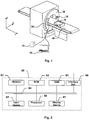
- Fig. 1 is a diagram showing the structure of a CT system according to an embodiment of the present disclosure.
- a CT device according to this embodiment comprises: a rack 20, a bearing mechanism 40, a controller 50, a computer data processor 60, or the like.
- the rack 20 comprises a ray source 10 configured to emitting X-ray for inspection, such as an X-ray machine, and a detection and collection apparatus 30.
- the bearing mechanism 40 bears a luggage to be inspected 70 to pass through the scanning area of the rack 20 between the ray source 10 and the detection and collection apparatus 30, while the rack 20 rotates about the travelling direction of the luggage to be inspected 70 such that the rays emitted from the ray source 10 are able to penetrate through the luggage to be inspected 70 and a CT scan is performed on the luggage to be inspected 70.
- the detection and collection apparatus 30 is, for example, a detector-and-data-collector with an integrated modular structure, such as a flat panel detector, for detecting rays transmitted through the object to be inspected such that analog signals are acquired and converted into digital signals, thereby outputting projection data of the luggage to be inspected 70 with respect to X-ray.
- the controller 50 is used for controlling various parts of the whole system to operate synchronously.
- the computer data processor 60 is used for processing the data collected by the data collector, processing and reconstructing the data, and outputting the result.
- the ray source 10 is located on a side of the object to be inspected
- the detection and collection apparatus 30 comprising a detector and a data collector is located on the other side of the luggage to be inspected 70 to acquire multi-angle projection data for the luggage to be inspected 70.
- the data collector may includes a data amplification shaping circuit which may operate in a (current) integration manner or a pulse (counting) manner.
- a data output cable of the detection and collection apparatus 30 is coupled to the controller 50 and the computer data processor 60, and stores the collected data into the computer data processor 60 based on a trigger command.
- Fig. 2 is a block diagram showing the structure of the computer data processor 60 as shown in Fig. 1 .
- the data collected by the data collector is stored into a memory 61 via an interface unit 68 and a bus 64.
- Configuration information and programs for the computer data processor are stored in a Read-Only Memory (ROM) 62.
- a Random Access Memory (RAM) 63 is used for temporarily storing various data during the operation of a processor 66.
- computer programs for data processing are also stored in the memory 61.
- the internal bus 64 connects the above memory 61, Read Only Memory (ROM) 62, Random Access Memory (RAM) 63, an input device 65, the processor 66, a display device 67, and the interface unit 68.
- the instruction code of the computer program instructs the processor 66 to perform a predetermined data processing algorithm.
- the display device 67 such as an LCD display, or output directly in a hardcopy form, such as printing.
- Fig. 3 is a block diagram showing the structure of a controller according to an embodiment of the present disclosure.
- the controller 50 comprises: a control unit 51 configured to control the ray source 10, the bearing mechanism 40, and the detection and collection apparatus 30 based on the instructions from the computer 60; a trigger signal generating unit 52 configured to generate a trigger command to trigger actions of the ray source 10, the detection and collection apparatus 30, and the bearing mechanism 40 under the control of the control unit; a first driving device 53 configured to drive the bearing mechanism 40 to transfer the luggage to be inspected 70 based on the trigger command which is generated by the trigger signal generating unit 52 under the control of the control unit 51; and a second driving device 54 configured to drive the rack 20 to rotate based on the trigger command which is generated by the trigger signal generating unit 52 under the control of the control unit 51.
- the projection data acquired by the detection and collection apparatus 30 is stored in the computer 60 for CT tomographic image reconstruction, thereby acquiring the tomographic image data for the luggage to be inspected 70.
- the computer 60 acquire a DR image for the luggage to be inspected 70 from at least one viewing direction based on the tomographic image data, for example, by executing software, to be displayed along with the reconstructed three-dimensional image, thereby facilitating a human operator for identifying to perform a inspection.
- the above CT imaging system may also be a dual-energy CT system, that is, the X-ray source 10 of the rack 20 may emit two types of rays having high-energy and low-energy, respectively.
- the computer data processor 60 may perform a dual-energy CT reconstruction to acquire equivalent atomic number and electron density data for various section layers of the luggage to be inspected 70.
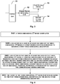
- Fig. 4 is a schematic flow chart showing a method for marking a target object according to an embodiment of the present disclosure.
- inspection data of an object to be inspected is read to display a three-dimensional image on a display screen.
- a selection of at least one area of the three-dimensional CT image at a first viewing direction is received from a user by an input device 65, such as a mouse, to generate a first three-dimensional description.
- an input device 65 such as a mouse
- the user may operate the input device 65 to marquee or circle an area on the image displayed on the screen at the current viewing direction.
- a selection of at least one area of the three-dimensional CT image at a second viewing direction is received from the user to generate a second three-dimensional description.
- the user may operate the input device 65 to marquee or circle an area on the image displayed on the screen at another viewing direction.
- the angle between the first viewing direction and the second viewing direction is in a predetermined range and the first three-dimensional description and the second three-dimensional description are related to at least one of dimensions, positions, or physical attributes of the target at the corresponding viewing direction.
- the angle between these two viewing directions may be in a range from 45 degrees to 135 degrees.
- the target in the three-dimensional CT image is determined based on the first three-dimensional description and the second three-dimensional description.
- a front plane depth map and a rear plane depth map at the first viewing direction is acquired, and a searching is performed in the front plane depth map and the rear plane depth map based on the area selected by the user at the first viewing direction, respectively, to generate a first bounding box/data subset as the first three-dimensional description.
- a three-dimensional drawing result at the second viewing direction is acquired by using the first generated bounding box/data subset as the drawing range, and a front plane depth map and a rear plane depth map at the second viewing direction are acquired.
- a searching is performed in the front plane depth map and the rear plane depth map based on the area selected by the user at the second viewing direction, respectively, to generate a second bounding box/data subset as the second three-dimensional description. In this way, an intersection operation is performed on the first bounding box/data subset and the second bounding box/data subset in the image space to determine the target.
- the step of acquiring the front plane depth map and the rear pane depth map may include: a depth test is performed in a scenario rendering process and the minimal depth value is recorded to acquire a front plane depth map.
- a depth test is performed in the scenario rendering process and the maximal depth value is recorded to acquire a rear plane depth map.
- both of the first bounding box/data subset and the second bounding box/data subset are bounding boxes/data subsets in any arbitrary direction.
- the marked area of the three-dimensional space is merged into and displayed with in the CT data.
- transparent areas are first removed to quickly acquire a tightly hierarchical bounding box/data subset for non-transparent area in the data.
- the above generated hierarchical bounding box/data subset is rendered to acquire the front/rear plane depth maps. These are the incident and exit positions of the adjusted projection rays.
- a first marking is performed in a current direction of line of sight, and a searching is performed in the front/rear plane depth maps by using an array of marked points to generate a bounding box, such as an OBB bounding box.
- the projection range of the rays is updated and a second marking is performed by the user at an orthogonal viewing direction which is reached by an automatic rotation to generate a new OBB bounding box.
- a Boolean intersection operation is performed on the OBB bounding boxes acquired in previous two steps in the image space to acquire a final marked area.
- the suspected area is merged and display in the original data by using a transfer function based on space constraints.
- Examples of the signal carrier media comprise but not limited to: a recordable medium such as floppy disk, hard drive, compact disk (CD), digital versatile disk (DVD), digital tape, computer memory, etc.; and a transmission medium, such as digital and/or analog communication medium (for example, optical fiber, waveguide, wired communication link, wireless communication link, etc.)
- a recordable medium such as floppy disk, hard drive, compact disk (CD), digital versatile disk (DVD), digital tape, computer memory, etc.
- a transmission medium such as digital and/or analog communication medium (for example, optical fiber, waveguide, wired communication link, wireless communication link, etc.)
Landscapes
- Physics & Mathematics (AREA)
- General Physics & Mathematics (AREA)
- Life Sciences & Earth Sciences (AREA)
- Health & Medical Sciences (AREA)
- Engineering & Computer Science (AREA)
- Theoretical Computer Science (AREA)
- High Energy & Nuclear Physics (AREA)
- Geophysics (AREA)
- General Life Sciences & Earth Sciences (AREA)
- Nuclear Medicine, Radiotherapy & Molecular Imaging (AREA)
- General Health & Medical Sciences (AREA)
- Radiology & Medical Imaging (AREA)
- Analytical Chemistry (AREA)
- Biochemistry (AREA)
- Immunology (AREA)
- Pathology (AREA)
- Chemical & Material Sciences (AREA)
- Pulmonology (AREA)
- Apparatus For Radiation Diagnosis (AREA)
- Analysing Materials By The Use Of Radiation (AREA)
Abstract
Description
- The present application relates to the field of inspection, and in particular, to methods for positing a target in a three-dimensional CT (Computerized Tomographic) image and inspection systems.
- A multi-energy X-ray inspection system is a new type of inspection systems developed based on a mono-energy X-ray inspection system. It can provide not only shape and content of an object to be inspected but also information about equivalent atomic number for the object to be inspected, to determine whether the object to be inspected is organics or inorganics, which can be displayed on a color monitor with different colors to facilitate human operators in identification.
- During an image identification process, if a suspected object is found, a human operator for identifying in the image is required to mark the suspected object with an input device, such as a mouse. For an item machine system of a DR (Digital Radiographic) type, the principle for marking a suspected object on a two-dimensional DR image is simple and there are many proven solutions. For an inspection system of a CT type, there is still a problem to be solved that how to mark a suspected object on a three-dimensional CT image in a quick and accurate manner.
- In view of one or more technical problems in the prior art, the present disclosure proposes a method for positioning a target in a three-dimensional CT image and an inspection system which may facilitate users in marking a suspected object in a CT image in a quick manner.
- In an aspect of the present disclosure, a method for positioning a target in a three-dimensional CT image is proposed, including the steps of: displaying a three-dimensional CT image; receiving a selection by a user of at least one area of the three-dimensional CT image at a first viewing direction to generate a first three-dimensional description; receiving a selection by the user of at least one area of the three-dimensional CT image at a second viewing direction to generate a second three-dimensional description, wherein the angle between the first viewing direction and the second viewing direction is in a predetermined range and the first three-dimensional description and the second three-dimensional description are related to at least one of dimensions, positions, or physical attributes of the target at the corresponding viewing direction; and determining the target in the three-dimensional CT image based on the first three-dimensional description and the second three-dimensional description.
- According to some embodiments, the step of generating the first three-dimensional description includes: acquiring a front plane depth map and a rear plane depth map at the first viewing direction, searching in the front plane depth map and the rear plane depth map based on the area selected by the user at the first viewing direction, respectively, to generate a first bounding box/data subset as the first three-dimensional description; wherein the step of generating the second three-dimensional description includes: acquiring a three-dimensional drawing result at the second viewing direction by using the first generated bounding box/data subset as the drawing range, and acquiring a front plane depth map and a rear plane depth map at the second viewing direction, searching in the front plane depth map and the rear plane depth map based on the area selected by the user at the second viewing direction, respectively, to generate a second bounding box/data subset as the second three-dimensional description; wherein the step of determining the target in the three-dimensional CT image comprises: performing an intersection operation on the first bounding box/data subset and the second bounding box/data subset in an image space to determine the target.
- According to some embodiments, the step of acquiring the front plane depth map and the rear plane depth map includes: performing a depth test in a scenario rendering process and recording the minimal depth value to acquire a front plane depth map; and performing a depth test in the scenario rendering process and recording the maximal depth value to acquire a rear plane depth map.
- According to some embodiments, both of the first bounding box/data subset and the second bounding box/data subset are bounding boxes/data subsets in any arbitrary direction.
- According to some embodiments, the marked area of the three-dimensional space is merged into and displayed with in the CT data.
- According to some embodiments, the predetermined range is specifically a range from 45 degrees to 135 degrees.
- In another aspect of the present disclosure, an inspection CT system is proposed, comprising: a CT scanning device configured to acquire inspection data for an object to be inspected; a memory configured to store the inspection data; a display device configured to display a three-dimensional CT image for the object to be inspected; an input device configured to input a selection by a user of at least one area of the three-dimensional CT image at a first viewing direction, and to input a selection by the user of at least one area of the three-dimensional CT image at a second viewing direction, wherein the angle between the first viewing direction and the second viewing direction is in a predetermined range; and a data processor configured to generate a first three-dimensional description based on the selection at the first viewing direction, generate a second three-dimensional description based on the selection at the second viewing direction, and determine the target in the three-dimensional CT image based on the first three-dimensional description and the second three-dimensional description, wherein the first three-dimensional description and the second three-dimensional description are related to at least one of the dimensions, positions or physical attributes of the target at corresponding viewing directions.
- According to some embodiments, the data processor is configured to acquire a front plane depth map and a rear plane depth map at the first viewing direction, search in the front plane depth map and the rear plane depth map based on the area selected by the user at the first viewing direction, respectively, to generate a first bounding box/data subset as the first three-dimensional description; acquire a three-dimensional drawing result at the second viewing direction by using the first generated bounding box/data subset as the drawing range, and acquire a front plane depth map and a rear plane depth map at the second viewing direction, search in the front plane depth map and the rear plane depth map based on the area selected by the user at the second viewing direction, respectively, to generate a second bounding box/data subset as the second three-dimensional description; and perform an intersection operation on the first bounding box/data subset and the second bounding box/data subset in an image space to determine the target.
- According to some embodiments, the data processor is configured to perform a depth test in a scenario rendering process and record the minimal depth value to acquire a front plane depth map; and perform a depth test in the scenario rendering process and record the maximal depth value to acquire a rear plane depth map.
- With the above technical solutions, the user may be facilitated in marking a suspected object in a CT image in a quick manner.
- To understand the present disclosure in a better way, a detailed description of the present disclosure will be given with reference to the following drawings, in which:
-
Fig. 1 is a diagram showing the structure of an inspection CT system according to an embodiment of the present disclosure; -
Fig. 2 is a block diagram showing the structure of the computer data processor as shown inFig. 1 ; -
Fig. 3 is a block diagram showing the structure of a controller according to an embodiment of the present disclosure; and -
Fig. 4 is a schematic flow chart showing a method for marking a target according to an embodiment of the present disclosure. - Specific embodiments of the present disclosure will be described in detail below and please note that the embodiments described herein are used for the purpose of exemplification rather than limitation of the present disclosure. Hereinafter, to provide a thorough understanding of the present disclosure, numerous specific details are set forth. However, it would be obvious for one ordinarily skilled in the art that the present disclosure can be practiced without these specific details. In other examples, known structures, materials, or methods are not described in detail to avoid any possible obfuscation of the present disclosure.
- Throughout the specification, the reference to "an embodiment", "the embodiment", "an example", or "the example" is meant that a specific feature, structure, or feature described with reference to this embodiment or example is contained by at least one embodiment of the present disclosure. Therefore, the phrases "in an embodiment", "in the embodiment", "an example", or "the example" throughout the specification is not necessarily intended to refer to a same embodiment or example. Further, specific features, structures, or characteristics may be combined into one or more embodiments or examples in any suitable combination and/or sub-combination. Further, it is appreciated by one ordinarily skilled in the art that the term "and/or" used herein comprises any and all combinations of one or more related items that are listed.
- With regard to the problem of the prior art that a target object cannot be marked quickly, the embodiments of the present disclosure propose a method for positioning an object in a three-dimensional CT image. First, a three-dimensional CT image for an object to be inspected is displayed on a display. Next, a selection of at least one area of the three-dimensional CT image at a first viewing direction is received from a user by an
input device 65, such as a mouse, to generate a first three-dimensional description. After that, a selection of at least one area of the three-dimensional CT image at a second viewing direction is received from the user, to generate a second three-dimensional description. The angle between the first viewing direction and the second viewing direction is in a predetermined range and the first three-dimensional description and the second three-dimensional description are related to at least one of dimensions, positions, or physical attributes of the target at the corresponding viewing direction. Finally, the target in the three-dimensional CT image is determined based on the first three-dimensional description and the second three-dimensional description. With the above technical solutions, the user may be facilitated in marking a suspected object in a CT image in a quick manner. -
Fig. 1 is a diagram showing the structure of a CT system according to an embodiment of the present disclosure. As shown inFig. 1 , a CT device according to this embodiment comprises: arack 20, abearing mechanism 40, acontroller 50, acomputer data processor 60, or the like. Therack 20 comprises aray source 10 configured to emitting X-ray for inspection, such as an X-ray machine, and a detection andcollection apparatus 30. Thebearing mechanism 40 bears a luggage to be inspected 70 to pass through the scanning area of therack 20 between theray source 10 and the detection andcollection apparatus 30, while therack 20 rotates about the travelling direction of the luggage to be inspected 70 such that the rays emitted from theray source 10 are able to penetrate through the luggage to be inspected 70 and a CT scan is performed on the luggage to be inspected 70. - The detection and
collection apparatus 30 is, for example, a detector-and-data-collector with an integrated modular structure, such as a flat panel detector, for detecting rays transmitted through the object to be inspected such that analog signals are acquired and converted into digital signals, thereby outputting projection data of the luggage to be inspected 70 with respect to X-ray. Thecontroller 50 is used for controlling various parts of the whole system to operate synchronously. Thecomputer data processor 60 is used for processing the data collected by the data collector, processing and reconstructing the data, and outputting the result. - As shown in
Fig. 1 , theray source 10 is located on a side of the object to be inspected, and the detection andcollection apparatus 30 comprising a detector and a data collector is located on the other side of the luggage to be inspected 70 to acquire multi-angle projection data for the luggage to be inspected 70. The data collector may includes a data amplification shaping circuit which may operate in a (current) integration manner or a pulse (counting) manner. A data output cable of the detection andcollection apparatus 30 is coupled to thecontroller 50 and thecomputer data processor 60, and stores the collected data into thecomputer data processor 60 based on a trigger command. -
Fig. 2 is a block diagram showing the structure of thecomputer data processor 60 as shown inFig. 1 . As shown inFig. 2 , the data collected by the data collector is stored into amemory 61 via aninterface unit 68 and abus 64. Configuration information and programs for the computer data processor are stored in a Read-Only Memory (ROM) 62. A Random Access Memory (RAM) 63 is used for temporarily storing various data during the operation of aprocessor 66. In addition, computer programs for data processing are also stored in thememory 61. Theinternal bus 64 connects theabove memory 61, Read Only Memory (ROM) 62, Random Access Memory (RAM) 63, aninput device 65, theprocessor 66, adisplay device 67, and theinterface unit 68. - After an operation command is input by a user via the
input device 65, such as a keyboard, a mouse, etc., the instruction code of the computer program instructs theprocessor 66 to perform a predetermined data processing algorithm. After the result of the data processing is acquired, it will be displayed on thedisplay device 67, such as an LCD display, or output directly in a hardcopy form, such as printing. -
Fig. 3 is a block diagram showing the structure of a controller according to an embodiment of the present disclosure. As shown inFig. 3 , thecontroller 50 comprises: acontrol unit 51 configured to control theray source 10, thebearing mechanism 40, and the detection andcollection apparatus 30 based on the instructions from thecomputer 60; a triggersignal generating unit 52 configured to generate a trigger command to trigger actions of theray source 10, the detection andcollection apparatus 30, and thebearing mechanism 40 under the control of the control unit; afirst driving device 53 configured to drive thebearing mechanism 40 to transfer the luggage to be inspected 70 based on the trigger command which is generated by the triggersignal generating unit 52 under the control of thecontrol unit 51; and asecond driving device 54 configured to drive therack 20 to rotate based on the trigger command which is generated by the triggersignal generating unit 52 under the control of thecontrol unit 51. The projection data acquired by the detection andcollection apparatus 30 is stored in thecomputer 60 for CT tomographic image reconstruction, thereby acquiring the tomographic image data for the luggage to be inspected 70. After that, thecomputer 60 acquire a DR image for the luggage to be inspected 70 from at least one viewing direction based on the tomographic image data, for example, by executing software, to be displayed along with the reconstructed three-dimensional image, thereby facilitating a human operator for identifying to perform a inspection. According to other embodiments, the above CT imaging system may also be a dual-energy CT system, that is, theX-ray source 10 of therack 20 may emit two types of rays having high-energy and low-energy, respectively. After the detection andcollection apparatus 30 detects the projection data with different energy levels, thecomputer data processor 60 may perform a dual-energy CT reconstruction to acquire equivalent atomic number and electron density data for various section layers of the luggage to be inspected 70. -
Fig. 4 is a schematic flow chart showing a method for marking a target object according to an embodiment of the present disclosure. - As shown in
Fig. 4 , at step S401, inspection data of an object to be inspected is read to display a three-dimensional image on a display screen. - At step S402, a selection of at least one area of the three-dimensional CT image at a first viewing direction is received from a user by an
input device 65, such as a mouse, to generate a first three-dimensional description. For example, the user may operate theinput device 65 to marquee or circle an area on the image displayed on the screen at the current viewing direction. - At step S403, a selection of at least one area of the three-dimensional CT image at a second viewing direction is received from the user to generate a second three-dimensional description. For example, the user may operate the
input device 65 to marquee or circle an area on the image displayed on the screen at another viewing direction. The angle between the first viewing direction and the second viewing direction is in a predetermined range and the first three-dimensional description and the second three-dimensional description are related to at least one of dimensions, positions, or physical attributes of the target at the corresponding viewing direction. For example, the angle between these two viewing directions may be in a range from 45 degrees to 135 degrees. - At step S404, the target in the three-dimensional CT image is determined based on the first three-dimensional description and the second three-dimensional description.
- Further, with regard to the problem of the prior art, after transparent areas in the data are quickly removed, new incident and exit positions of the projection rays are acquired and recorded as a depth map. Based thereon, a two-dimensional mark is restored to its depth information in the voxel space. A Boolean intersection operation is performed on the two acquired geometries in the image space to finally acquire a marked area in the three-dimensional space.
- For example, a front plane depth map and a rear plane depth map at the first viewing direction is acquired, and a searching is performed in the front plane depth map and the rear plane depth map based on the area selected by the user at the first viewing direction, respectively, to generate a first bounding box/data subset as the first three-dimensional description. A three-dimensional drawing result at the second viewing direction is acquired by using the first generated bounding box/data subset as the drawing range, and a front plane depth map and a rear plane depth map at the second viewing direction are acquired. A searching is performed in the front plane depth map and the rear plane depth map based on the area selected by the user at the second viewing direction, respectively, to generate a second bounding box/data subset as the second three-dimensional description. In this way, an intersection operation is performed on the first bounding box/data subset and the second bounding box/data subset in the image space to determine the target.
- In other embodiments, the step of acquiring the front plane depth map and the rear pane depth map may include: a depth test is performed in a scenario rendering process and the minimal depth value is recorded to acquire a front plane depth map. A depth test is performed in the scenario rendering process and the maximal depth value is recorded to acquire a rear plane depth map. For example, both of the first bounding box/data subset and the second bounding box/data subset are bounding boxes/data subsets in any arbitrary direction.
- In some embodiments, the marked area of the three-dimensional space is merged into and displayed with in the CT data.
- For example, in some embodiments, transparent areas are first removed to quickly acquire a tightly hierarchical bounding box/data subset for non-transparent area in the data. After that, the above generated hierarchical bounding box/data subset is rendered to acquire the front/rear plane depth maps. These are the incident and exit positions of the adjusted projection rays. Next, a first marking is performed in a current direction of line of sight, and a searching is performed in the front/rear plane depth maps by using an array of marked points to generate a bounding box, such as an OBB bounding box. After that, based on the above generated OBB bounding box, the projection range of the rays is updated and a second marking is performed by the user at an orthogonal viewing direction which is reached by an automatic rotation to generate a new OBB bounding box. A Boolean intersection operation is performed on the OBB bounding boxes acquired in previous two steps in the image space to acquire a final marked area. Finally, the suspected area is merged and display in the original data by using a transfer function based on space constraints. By using the marking method of the present disclosure, the transparent areas in the CT data may be removed quickly and accurately to facilitate the user in quickly accomplishing the suspected area marking task in a friendly operation manner.
- The above detailed description has already set forth numerous embodiments of the method and apparatus for marking a suspected object in an inspection CT system with reference to the diagrams, flow charts, and/or examples. In the case where the diagrams, flow charts, and/or examples comprise one or more functions and/or operations, one skilled in the art should appreciate that each function and/or operation in the diagrams, flow charts, or examples may be implemented by various structures, hardware, software, firmware or any combination thereof either alone and/or in any combination. In an embodiment, several parts of the subject matter described in the embodiments of the present disclosure may be implemented by Application Specific Integrated Circuit (ASIC), Field Programmable Gate Array (FPGA), Digital Signal Processor (DSP), or any other integrated form. However, one skilled in the art should appreciate that some aspects of the embodiment disclosed herein may be partially or wholly implemented in an integrated circuit equivalently, implemented as one or more computer programs running on one or more computers (for example, one or more programs running on one or more computer systems), implemented as one or more programs running on one or more processors (for example, one or more programs running on one or more micro-processors), implemented as firmware, or substantially any combination thereof, and one skilled in the art is capable to design the circuit and/or write software and/or firmware code. Further, one skilled in the art would appreciate that the mechanism of the subject matter of the present disclosure may be distributed in various forms of program products, and the exemplary embodiments of the subject matter of the present disclosure may be applicable irrespective of the specific types of signal carrier media for distribution. Examples of the signal carrier media comprise but not limited to: a recordable medium such as floppy disk, hard drive, compact disk (CD), digital versatile disk (DVD), digital tape, computer memory, etc.; and a transmission medium, such as digital and/or analog communication medium (for example, optical fiber, waveguide, wired communication link, wireless communication link, etc.)
- Although the present disclosure is already described with reference to several typical embodiments, it is to be appreciated that the terms used herein are illustrative and exemplary, rather than limiting. Since the present disclosure may be practice in multiple forms without departing from the spirit or essence, it is to be noted that the above embodiments are not limited to any previously described details and shall be interpreted broadly within the spirit and scope defined by the claims. Therefore, all changes and variations fall into the scope of the claims or their equivalents shall be embraced by the claims.
Claims (9)
- A method for positioning a target in a three-dimensional CT image, characterized in that it comprises the steps of:displaying a three-dimensional CT image (S401);receiving a selection by a user of at least one area of the three-dimensional CT image at a first viewing direction to generate a first three-dimensional description (S402);receiving a selection by the user of at least one area of the three-dimensional CT image at a second viewing direction to generate a second three-dimensional description (S403), wherein the angle between the first viewing direction and the second viewing direction is in a predetermined range and the first three-dimensional description and the second three-dimensional description are related to at least one of dimensions, positions, or physical attributes of the target at the corresponding viewing direction; anddetermining the target in the three-dimensional CT image based on the first three-dimensional description and the second three-dimensional description (S404).
- The method according to Claim 1, characterized in that the step of generating the first three-dimensional description comprises:acquiring a front plane depth map and a rear plane depth map at the first viewing direction, searching in the front plane depth map and the rear plane depth map based on the area selected by the user at the first viewing direction, respectively, to generate a first bounding box/data subset as the first three-dimensional description;wherein the step of generating the second three-dimensional description comprises:acquiring a three-dimensional drawing result at the second viewing direction by using the first generated bounding box/data subset as the drawing range, and acquiring a front plane depth map and a rear plane depth map at the second viewing direction, searching in the front plane depth map and the rear plane depth map based on the area selected by the user at the second viewing direction, respectively, to generate a second bounding box/data subset as the second three-dimensional description;wherein the step of determining the target in the three-dimensional CT image comprises:performing an intersection operation on the first bounding box/data subset and the second bounding box/data subset in an image space to determine the target.
- The method according to Claim 2, characterized in that the step of acquiring the front plane depth map and the rear plane depth map comprises:performing a depth test in a scenario rendering process and recording the minimal depth value to acquire a front plane depth map; andperforming a depth test in the scenario rendering process and recording the maximal depth value to acquire a rear plane depth map.
- The method according to Claim 2, characterized in that both of the first bounding box/data subset and the second bounding box/data subset are bounding boxes/data subsets in any arbitrary direction.
- The method according to Claim 2, characterized in that the marked area of the three-dimensional space is merged into and displayed with in the CT data.
- The method according to Claim 1, characterized in that the predetermined range is specifically a range from 45 degrees to 135 degrees.
- An inspection CT system characterized in that it comprises:a CT scanning device (10,20,30,50) configured to acquire inspection data for an object to be inspected;a memory (61) configured to store the inspection data;a display device (67) configured to display a three-dimensional CT image for the object to be inspected;an input device (65) configured to input a selection by a user of at least one area of the three-dimensional CT image at a first viewing direction, and to input a selection by the user of at least one area of the three-dimensional CT image at a second viewing direction, wherein the angle between the first viewing direction and the second viewing direction is in a predetermined range; anda data processor (66) configured to generate a first three-dimensional description based on the selection at the first viewing direction, generate a second three-dimensional description based on the selection at the second viewing direction, and determine the target in the three-dimensional CT image based on the first three-dimensional description and the second three-dimensional description, wherein the first three-dimensional description and the second three-dimensional description are related to at least one of the dimensions, positions or physical attributes of the target at corresponding viewing directions.
- The inspection system according to Claim 7, characterized in that the data processor (66) is configured to:acquire a front plane depth map and a rear plane depth map at the first viewing direction, search in the front plane depth map and the rear plane depth map based on the area selected by the user at the first viewing direction, respectively, to generate a first bounding box/data subset as the first three-dimensional description;acquire a three-dimensional drawing result at the second viewing direction by using the first generated bounding box/data subset as the drawing range, and acquire a front plane depth map and a rear plane depth map at the second viewing direction, search in the front plane depth map and the rear plane depth map based on the area selected by the user at the second viewing direction, respectively, to generate a second bounding box/data subset as the second three-dimensional description; andperform an intersection operation on the first bounding box/data subset and the second bounding box/data subset in an image space to determine the target.
- The inspection system according to Claim 8, wherein the data processor is configured to:perform a depth test in a scenario rendering process and record the minimal depth value to acquire a front plane depth map; andperform a depth test in the scenario rendering process and record the maximal depth value to acquire a rear plane depth map.
Applications Claiming Priority (2)
| Application Number | Priority Date | Filing Date | Title |
|---|---|---|---|
| CN201410795840.1A CN105784731B (en) | 2014-06-25 | 2014-12-18 | A method and security inspection system for locating a target in a three-dimensional CT image |
| PCT/CN2015/097378 WO2016095798A1 (en) | 2014-12-18 | 2015-12-15 | Method for positioning target in three-dimensional ct image and security check system |
Publications (4)
| Publication Number | Publication Date |
|---|---|
| EP3112852A1 true EP3112852A1 (en) | 2017-01-04 |
| EP3112852A4 EP3112852A4 (en) | 2017-10-11 |
| EP3112852C0 EP3112852C0 (en) | 2024-08-28 |
| EP3112852B1 EP3112852B1 (en) | 2024-08-28 |
Family
ID=56125933
Family Applications (1)
| Application Number | Title | Priority Date | Filing Date |
|---|---|---|---|
| EP15869305.1A Active EP3112852B1 (en) | 2014-12-18 | 2015-12-15 | Method for positioning target in three-dimensional ct image and security check system |
Country Status (3)
| Country | Link |
|---|---|
| US (1) | US10145977B2 (en) |
| EP (1) | EP3112852B1 (en) |
| WO (1) | WO2016095798A1 (en) |
Families Citing this family (7)
| Publication number | Priority date | Publication date | Assignee | Title |
|---|---|---|---|---|
| CN108508042A (en) * | 2018-04-02 | 2018-09-07 | 合肥工业大学 | Multi-view X ray coal and spoil transmission image detection method and device |
| CN113643361B (en) * | 2020-05-11 | 2025-01-10 | 同方威视技术股份有限公司 | Target area positioning method, device, equipment, medium and program product |
| CN113830510B (en) * | 2020-06-23 | 2023-05-23 | 同方威视技术股份有限公司 | Conveying device and inspection system |
| CN112598682B (en) * | 2020-12-25 | 2024-03-29 | 公安部第一研究所 | Three-dimensional CT image sectioning method and device based on any angle |
| CN113112560B (en) * | 2021-04-14 | 2023-10-03 | 杭州柳叶刀机器人有限公司 | Physiological point area marking method and device |
| CN113935975B (en) * | 2021-10-20 | 2025-04-08 | 北京航星机器制造有限公司 | A method and system for inserting dangerous goods images for security inspection CT |
| CN116188385A (en) * | 2022-12-28 | 2023-05-30 | 同方威视技术股份有限公司 | Method and device for stripping target object in three-dimensional CT image, and security CT system |
Family Cites Families (10)
| Publication number | Priority date | Publication date | Assignee | Title |
|---|---|---|---|---|
| US6721387B1 (en) | 2001-06-13 | 2004-04-13 | Analogic Corporation | Method of and system for reducing metal artifacts in images generated by x-ray scanning devices |
| US7606349B2 (en) * | 2006-02-09 | 2009-10-20 | L-3 Communications Security and Detection Systems Inc. | Selective generation of radiation at multiple energy levels |
| US20080123895A1 (en) * | 2006-11-27 | 2008-05-29 | Todd Gable | Method and system for fast volume cropping of three-dimensional image data |
| US7978191B2 (en) * | 2007-09-24 | 2011-07-12 | Dolphin Imaging Systems, Llc | System and method for locating anatomies of interest in a 3D volume |
| JP4676021B2 (en) * | 2009-04-16 | 2011-04-27 | 富士フイルム株式会社 | Diagnosis support apparatus, diagnosis support program, and diagnosis support method |
| CN101592579B (en) | 2009-07-03 | 2011-07-06 | 公安部第一研究所 | Method and device for automatically detecting explosive substances in luggage by using multi-view X rays |
| US8750585B2 (en) * | 2009-10-13 | 2014-06-10 | Agency For Science, Technology And Research | Method and system for segmenting a liver object in an image |
| CN102222352B (en) * | 2010-04-16 | 2014-07-23 | 株式会社日立医疗器械 | Image processing method and image processing apparatus |
| CN103713329B (en) | 2012-09-29 | 2016-12-21 | 清华大学 | CT imaging positions method and the equipment of object |
| CN105785462B (en) * | 2014-06-25 | 2019-02-22 | 同方威视技术股份有限公司 | A method and security inspection CT system for locating a target in a three-dimensional CT image |
-
2015
- 2015-12-15 WO PCT/CN2015/097378 patent/WO2016095798A1/en not_active Ceased
- 2015-12-15 EP EP15869305.1A patent/EP3112852B1/en active Active
- 2015-12-15 US US15/300,668 patent/US10145977B2/en active Active
Also Published As
| Publication number | Publication date |
|---|---|
| US20170176631A1 (en) | 2017-06-22 |
| US10145977B2 (en) | 2018-12-04 |
| EP3112852A4 (en) | 2017-10-11 |
| EP3112852C0 (en) | 2024-08-28 |
| EP3112852B1 (en) | 2024-08-28 |
| WO2016095798A1 (en) | 2016-06-23 |
Similar Documents
| Publication | Publication Date | Title |
|---|---|---|
| US10297050B2 (en) | Methods for positioning a target in a three-dimensional CT image and CT systems for security inspection | |
| EP3112852B1 (en) | Method for positioning target in three-dimensional ct image and security check system | |
| US8989342B2 (en) | Methods and systems for volumetric reconstruction using radiography | |
| US9058658B2 (en) | Methods and devices for locating object in CT imaging | |
| WO2015172726A1 (en) | Image display method | |
| CN108240997B (en) | Inspection apparatus and method of inspecting container | |
| CN105849772B (en) | Inspection system and method | |
| JP2019025331A (en) | Radiation transmission/fluorescence ct imaging system and imaging method | |
| WO2010135900A1 (en) | Dual-energy under-sampling material discriminating method and system | |
| EP3112909B1 (en) | Method for positioning target in three-dimensional ct image and security check ct system | |
| US11480533B1 (en) | Multi-scan computed tomography defect detectability | |
| CN105612433A (en) | Synthesized imaging of chromatographic X-ray photographing | |
| US20250363635A1 (en) | Out-of-view ct scan detection | |
| AU2023420138A1 (en) | Method and apparatus for separating target object in three-dimensional ct image, and security inspection ct system | |
| CN201043955Y (en) | Dual View Scanning Radiation Imaging Device | |
| US6445762B1 (en) | Methods and apparatus for defining regions of interest | |
| CN112950664A (en) | Target object positioning and labeling method and device based on sliding profile | |
| HK1217796B (en) | Image display methods | |
| HK1218157B (en) | Ct system for security check and method thereof | |
| HK1150074A (en) | Dual-energy under-sampling material discriminating method and system |
Legal Events
| Date | Code | Title | Description |
|---|---|---|---|
| PUAI | Public reference made under article 153(3) epc to a published international application that has entered the european phase |
Free format text: ORIGINAL CODE: 0009012 |
|
| STAA | Information on the status of an ep patent application or granted ep patent |
Free format text: STATUS: REQUEST FOR EXAMINATION WAS MADE |
|
| 17P | Request for examination filed |
Effective date: 20160929 |
|
| AK | Designated contracting states |
Kind code of ref document: A1 Designated state(s): AL AT BE BG CH CY CZ DE DK EE ES FI FR GB GR HR HU IE IS IT LI LT LU LV MC MK MT NL NO PL PT RO RS SE SI SK SM TR |
|
| AX | Request for extension of the european patent |
Extension state: BA ME |
|
| A4 | Supplementary search report drawn up and despatched |
Effective date: 20170907 |
|
| RIC1 | Information provided on ipc code assigned before grant |
Ipc: G01N 23/04 20060101AFI20170901BHEP Ipc: G01V 5/00 20060101ALI20170901BHEP |
|
| DAV | Request for validation of the european patent (deleted) | ||
| DAX | Request for extension of the european patent (deleted) | ||
| STAA | Information on the status of an ep patent application or granted ep patent |
Free format text: STATUS: EXAMINATION IS IN PROGRESS |
|
| 17Q | First examination report despatched |
Effective date: 20180725 |
|
| GRAP | Despatch of communication of intention to grant a patent |
Free format text: ORIGINAL CODE: EPIDOSNIGR1 |
|
| STAA | Information on the status of an ep patent application or granted ep patent |
Free format text: STATUS: GRANT OF PATENT IS INTENDED |
|
| INTG | Intention to grant announced |
Effective date: 20240322 |
|
| GRAS | Grant fee paid |
Free format text: ORIGINAL CODE: EPIDOSNIGR3 |
|
| GRAA | (expected) grant |
Free format text: ORIGINAL CODE: 0009210 |
|
| STAA | Information on the status of an ep patent application or granted ep patent |
Free format text: STATUS: THE PATENT HAS BEEN GRANTED |
|
| AK | Designated contracting states |
Kind code of ref document: B1 Designated state(s): AL AT BE BG CH CY CZ DE DK EE ES FI FR GB GR HR HU IE IS IT LI LT LU LV MC MK MT NL NO PL PT RO RS SE SI SK SM TR |
|
| REG | Reference to a national code |
Ref country code: GB Ref legal event code: FG4D |
|
| REG | Reference to a national code |
Ref country code: CH Ref legal event code: EP |
|
| REG | Reference to a national code |
Ref country code: DE Ref legal event code: R096 Ref document number: 602015089716 Country of ref document: DE |
|
| REG | Reference to a national code |
Ref country code: IE Ref legal event code: FG4D |
|
| U01 | Request for unitary effect filed |
Effective date: 20240930 |
|
| U07 | Unitary effect registered |
Designated state(s): AT BE BG DE DK EE FI FR IT LT LU LV MT NL PT RO SE SI Effective date: 20241024 |
|
| U1N | Appointed representative for the unitary patent procedure changed after the registration of the unitary effect |
Representative=s name: TREEBY, PHILIP DAVID WILLIAM; GB |
|
| U20 | Renewal fee for the european patent with unitary effect paid |
Year of fee payment: 10 Effective date: 20241205 |
|
| PG25 | Lapsed in a contracting state [announced via postgrant information from national office to epo] |
Ref country code: NO Free format text: LAPSE BECAUSE OF FAILURE TO SUBMIT A TRANSLATION OF THE DESCRIPTION OR TO PAY THE FEE WITHIN THE PRESCRIBED TIME-LIMIT Effective date: 20241128 |
|
| PG25 | Lapsed in a contracting state [announced via postgrant information from national office to epo] |
Ref country code: GR Free format text: LAPSE BECAUSE OF FAILURE TO SUBMIT A TRANSLATION OF THE DESCRIPTION OR TO PAY THE FEE WITHIN THE PRESCRIBED TIME-LIMIT Effective date: 20241129 Ref country code: PL Free format text: LAPSE BECAUSE OF FAILURE TO SUBMIT A TRANSLATION OF THE DESCRIPTION OR TO PAY THE FEE WITHIN THE PRESCRIBED TIME-LIMIT Effective date: 20240828 |
|
| PG25 | Lapsed in a contracting state [announced via postgrant information from national office to epo] |
Ref country code: IS Free format text: LAPSE BECAUSE OF FAILURE TO SUBMIT A TRANSLATION OF THE DESCRIPTION OR TO PAY THE FEE WITHIN THE PRESCRIBED TIME-LIMIT Effective date: 20241228 |
|
| PG25 | Lapsed in a contracting state [announced via postgrant information from national office to epo] |
Ref country code: HR Free format text: LAPSE BECAUSE OF FAILURE TO SUBMIT A TRANSLATION OF THE DESCRIPTION OR TO PAY THE FEE WITHIN THE PRESCRIBED TIME-LIMIT Effective date: 20240828 |
|
| PG25 | Lapsed in a contracting state [announced via postgrant information from national office to epo] |
Ref country code: RS Free format text: LAPSE BECAUSE OF FAILURE TO SUBMIT A TRANSLATION OF THE DESCRIPTION OR TO PAY THE FEE WITHIN THE PRESCRIBED TIME-LIMIT Effective date: 20241128 Ref country code: ES Free format text: LAPSE BECAUSE OF FAILURE TO SUBMIT A TRANSLATION OF THE DESCRIPTION OR TO PAY THE FEE WITHIN THE PRESCRIBED TIME-LIMIT Effective date: 20240828 |
|
| PG25 | Lapsed in a contracting state [announced via postgrant information from national office to epo] |
Ref country code: RS Free format text: LAPSE BECAUSE OF FAILURE TO SUBMIT A TRANSLATION OF THE DESCRIPTION OR TO PAY THE FEE WITHIN THE PRESCRIBED TIME-LIMIT Effective date: 20241128 Ref country code: PL Free format text: LAPSE BECAUSE OF FAILURE TO SUBMIT A TRANSLATION OF THE DESCRIPTION OR TO PAY THE FEE WITHIN THE PRESCRIBED TIME-LIMIT Effective date: 20240828 Ref country code: NO Free format text: LAPSE BECAUSE OF FAILURE TO SUBMIT A TRANSLATION OF THE DESCRIPTION OR TO PAY THE FEE WITHIN THE PRESCRIBED TIME-LIMIT Effective date: 20241128 Ref country code: IS Free format text: LAPSE BECAUSE OF FAILURE TO SUBMIT A TRANSLATION OF THE DESCRIPTION OR TO PAY THE FEE WITHIN THE PRESCRIBED TIME-LIMIT Effective date: 20241228 Ref country code: HR Free format text: LAPSE BECAUSE OF FAILURE TO SUBMIT A TRANSLATION OF THE DESCRIPTION OR TO PAY THE FEE WITHIN THE PRESCRIBED TIME-LIMIT Effective date: 20240828 Ref country code: GR Free format text: LAPSE BECAUSE OF FAILURE TO SUBMIT A TRANSLATION OF THE DESCRIPTION OR TO PAY THE FEE WITHIN THE PRESCRIBED TIME-LIMIT Effective date: 20241129 Ref country code: ES Free format text: LAPSE BECAUSE OF FAILURE TO SUBMIT A TRANSLATION OF THE DESCRIPTION OR TO PAY THE FEE WITHIN THE PRESCRIBED TIME-LIMIT Effective date: 20240828 |
|
| PG25 | Lapsed in a contracting state [announced via postgrant information from national office to epo] |
Ref country code: SM Free format text: LAPSE BECAUSE OF FAILURE TO SUBMIT A TRANSLATION OF THE DESCRIPTION OR TO PAY THE FEE WITHIN THE PRESCRIBED TIME-LIMIT Effective date: 20240828 |
|
| PG25 | Lapsed in a contracting state [announced via postgrant information from national office to epo] |
Ref country code: CZ Free format text: LAPSE BECAUSE OF FAILURE TO SUBMIT A TRANSLATION OF THE DESCRIPTION OR TO PAY THE FEE WITHIN THE PRESCRIBED TIME-LIMIT Effective date: 20240828 |
|
| PG25 | Lapsed in a contracting state [announced via postgrant information from national office to epo] |
Ref country code: SK Free format text: LAPSE BECAUSE OF FAILURE TO SUBMIT A TRANSLATION OF THE DESCRIPTION OR TO PAY THE FEE WITHIN THE PRESCRIBED TIME-LIMIT Effective date: 20240828 |
|
| PLBE | No opposition filed within time limit |
Free format text: ORIGINAL CODE: 0009261 |
|
| STAA | Information on the status of an ep patent application or granted ep patent |
Free format text: STATUS: NO OPPOSITION FILED WITHIN TIME LIMIT |
|
| PG25 | Lapsed in a contracting state [announced via postgrant information from national office to epo] |
Ref country code: MC Free format text: LAPSE BECAUSE OF FAILURE TO SUBMIT A TRANSLATION OF THE DESCRIPTION OR TO PAY THE FEE WITHIN THE PRESCRIBED TIME-LIMIT Effective date: 20240828 |
|
| REG | Reference to a national code |
Ref country code: CH Ref legal event code: PL |
|
| 26N | No opposition filed |
Effective date: 20250530 |
|
| GBPC | Gb: european patent ceased through non-payment of renewal fee |
Effective date: 20241215 |
|
| PG25 | Lapsed in a contracting state [announced via postgrant information from national office to epo] |
Ref country code: GB Free format text: LAPSE BECAUSE OF NON-PAYMENT OF DUE FEES Effective date: 20241215 |
|
| PG25 | Lapsed in a contracting state [announced via postgrant information from national office to epo] |
Ref country code: CH Free format text: LAPSE BECAUSE OF NON-PAYMENT OF DUE FEES Effective date: 20241231 |
|
| PG25 | Lapsed in a contracting state [announced via postgrant information from national office to epo] |
Ref country code: IE Free format text: LAPSE BECAUSE OF NON-PAYMENT OF DUE FEES Effective date: 20241215 |
|
| U20 | Renewal fee for the european patent with unitary effect paid |
Year of fee payment: 11 Effective date: 20251208 |
|
| PG25 | Lapsed in a contracting state [announced via postgrant information from national office to epo] |
Ref country code: CY Free format text: LAPSE BECAUSE OF FAILURE TO SUBMIT A TRANSLATION OF THE DESCRIPTION OR TO PAY THE FEE WITHIN THE PRESCRIBED TIME-LIMIT Effective date: 20240828 |
|
| PG25 | Lapsed in a contracting state [announced via postgrant information from national office to epo] |
Ref country code: TR Free format text: LAPSE BECAUSE OF FAILURE TO SUBMIT A TRANSLATION OF THE DESCRIPTION OR TO PAY THE FEE WITHIN THE PRESCRIBED TIME-LIMIT Effective date: 20240828 |
|
| PG25 | Lapsed in a contracting state [announced via postgrant information from national office to epo] |
Ref country code: HU Free format text: LAPSE BECAUSE OF FAILURE TO SUBMIT A TRANSLATION OF THE DESCRIPTION OR TO PAY THE FEE WITHIN THE PRESCRIBED TIME-LIMIT; INVALID AB INITIO Effective date: 20151215 |