EP3112726A1 - Clutch control device for four-wheel drive vehicle - Google Patents
Clutch control device for four-wheel drive vehicle Download PDFInfo
- Publication number
- EP3112726A1 EP3112726A1 EP15756056.6A EP15756056A EP3112726A1 EP 3112726 A1 EP3112726 A1 EP 3112726A1 EP 15756056 A EP15756056 A EP 15756056A EP 3112726 A1 EP3112726 A1 EP 3112726A1
- Authority
- EP
- European Patent Office
- Prior art keywords
- clutch
- oil
- chamber
- wheel drive
- lubrication oil
- Prior art date
- Legal status (The legal status is an assumption and is not a legal conclusion. Google has not performed a legal analysis and makes no representation as to the accuracy of the status listed.)
- Granted
Links
- 238000005461 lubrication Methods 0.000 claims abstract description 118
- 238000003756 stirring Methods 0.000 claims abstract description 47
- 238000005192 partition Methods 0.000 claims description 13
- 238000004891 communication Methods 0.000 claims description 12
- 230000003247 decreasing effect Effects 0.000 claims description 5
- 230000008878 coupling Effects 0.000 abstract description 137
- 238000010168 coupling process Methods 0.000 abstract description 137
- 238000005859 coupling reaction Methods 0.000 abstract description 137
- 230000000717 retained effect Effects 0.000 abstract 1
- 230000007704 transition Effects 0.000 description 19
- 238000000034 method Methods 0.000 description 16
- 230000008569 process Effects 0.000 description 16
- 239000000446 fuel Substances 0.000 description 9
- 230000005540 biological transmission Effects 0.000 description 8
- 230000000694 effects Effects 0.000 description 7
- 230000006872 improvement Effects 0.000 description 6
- 230000009471 action Effects 0.000 description 5
- 230000007423 decrease Effects 0.000 description 3
- 238000001514 detection method Methods 0.000 description 3
- 238000010438 heat treatment Methods 0.000 description 3
- 230000001105 regulatory effect Effects 0.000 description 3
- 238000007792 addition Methods 0.000 description 1
- 238000013461 design Methods 0.000 description 1
- 239000012530 fluid Substances 0.000 description 1
- 230000001050 lubricating effect Effects 0.000 description 1
- 238000012986 modification Methods 0.000 description 1
- 230000004048 modification Effects 0.000 description 1
- 230000001681 protective effect Effects 0.000 description 1
- 230000004044 response Effects 0.000 description 1
- 230000004043 responsiveness Effects 0.000 description 1
- 238000012546 transfer Methods 0.000 description 1
- 238000011144 upstream manufacturing Methods 0.000 description 1
Images



Classifications
-
- B—PERFORMING OPERATIONS; TRANSPORTING
- B60—VEHICLES IN GENERAL
- B60K—ARRANGEMENT OR MOUNTING OF PROPULSION UNITS OR OF TRANSMISSIONS IN VEHICLES; ARRANGEMENT OR MOUNTING OF PLURAL DIVERSE PRIME-MOVERS IN VEHICLES; AUXILIARY DRIVES FOR VEHICLES; INSTRUMENTATION OR DASHBOARDS FOR VEHICLES; ARRANGEMENTS IN CONNECTION WITH COOLING, AIR INTAKE, GAS EXHAUST OR FUEL SUPPLY OF PROPULSION UNITS IN VEHICLES
- B60K23/00—Arrangement or mounting of control devices for vehicle transmissions, or parts thereof, not otherwise provided for
- B60K23/08—Arrangement or mounting of control devices for vehicle transmissions, or parts thereof, not otherwise provided for for changing number of driven wheels, for switching from driving one axle to driving two or more axles
-
- F—MECHANICAL ENGINEERING; LIGHTING; HEATING; WEAPONS; BLASTING
- F16—ENGINEERING ELEMENTS AND UNITS; GENERAL MEASURES FOR PRODUCING AND MAINTAINING EFFECTIVE FUNCTIONING OF MACHINES OR INSTALLATIONS; THERMAL INSULATION IN GENERAL
- F16D—COUPLINGS FOR TRANSMITTING ROTATION; CLUTCHES; BRAKES
- F16D48/00—External control of clutches
- F16D48/06—Control by electric or electronic means, e.g. of fluid pressure
- F16D48/066—Control of fluid pressure, e.g. using an accumulator
-
- B—PERFORMING OPERATIONS; TRANSPORTING
- B60—VEHICLES IN GENERAL
- B60K—ARRANGEMENT OR MOUNTING OF PROPULSION UNITS OR OF TRANSMISSIONS IN VEHICLES; ARRANGEMENT OR MOUNTING OF PLURAL DIVERSE PRIME-MOVERS IN VEHICLES; AUXILIARY DRIVES FOR VEHICLES; INSTRUMENTATION OR DASHBOARDS FOR VEHICLES; ARRANGEMENTS IN CONNECTION WITH COOLING, AIR INTAKE, GAS EXHAUST OR FUEL SUPPLY OF PROPULSION UNITS IN VEHICLES
- B60K17/00—Arrangement or mounting of transmissions in vehicles
- B60K17/02—Arrangement or mounting of transmissions in vehicles characterised by arrangement, location, or kind of clutch
-
- B—PERFORMING OPERATIONS; TRANSPORTING
- B60—VEHICLES IN GENERAL
- B60K—ARRANGEMENT OR MOUNTING OF PROPULSION UNITS OR OF TRANSMISSIONS IN VEHICLES; ARRANGEMENT OR MOUNTING OF PLURAL DIVERSE PRIME-MOVERS IN VEHICLES; AUXILIARY DRIVES FOR VEHICLES; INSTRUMENTATION OR DASHBOARDS FOR VEHICLES; ARRANGEMENTS IN CONNECTION WITH COOLING, AIR INTAKE, GAS EXHAUST OR FUEL SUPPLY OF PROPULSION UNITS IN VEHICLES
- B60K17/00—Arrangement or mounting of transmissions in vehicles
- B60K17/34—Arrangement or mounting of transmissions in vehicles for driving both front and rear wheels, e.g. four wheel drive vehicles
- B60K17/344—Arrangement or mounting of transmissions in vehicles for driving both front and rear wheels, e.g. four wheel drive vehicles having a transfer gear
- B60K17/346—Arrangement or mounting of transmissions in vehicles for driving both front and rear wheels, e.g. four wheel drive vehicles having a transfer gear the transfer gear being a differential gear
- B60K17/3467—Arrangement or mounting of transmissions in vehicles for driving both front and rear wheels, e.g. four wheel drive vehicles having a transfer gear the transfer gear being a differential gear combined with a change speed gearing, e.g. range gear
-
- B—PERFORMING OPERATIONS; TRANSPORTING
- B60—VEHICLES IN GENERAL
- B60K—ARRANGEMENT OR MOUNTING OF PROPULSION UNITS OR OF TRANSMISSIONS IN VEHICLES; ARRANGEMENT OR MOUNTING OF PLURAL DIVERSE PRIME-MOVERS IN VEHICLES; AUXILIARY DRIVES FOR VEHICLES; INSTRUMENTATION OR DASHBOARDS FOR VEHICLES; ARRANGEMENTS IN CONNECTION WITH COOLING, AIR INTAKE, GAS EXHAUST OR FUEL SUPPLY OF PROPULSION UNITS IN VEHICLES
- B60K17/00—Arrangement or mounting of transmissions in vehicles
- B60K17/34—Arrangement or mounting of transmissions in vehicles for driving both front and rear wheels, e.g. four wheel drive vehicles
- B60K17/348—Arrangement or mounting of transmissions in vehicles for driving both front and rear wheels, e.g. four wheel drive vehicles having differential means for driving one set of wheels, e.g. the front, at one speed and the other set, e.g. the rear, at a different speed
-
- B—PERFORMING OPERATIONS; TRANSPORTING
- B60—VEHICLES IN GENERAL
- B60K—ARRANGEMENT OR MOUNTING OF PROPULSION UNITS OR OF TRANSMISSIONS IN VEHICLES; ARRANGEMENT OR MOUNTING OF PLURAL DIVERSE PRIME-MOVERS IN VEHICLES; AUXILIARY DRIVES FOR VEHICLES; INSTRUMENTATION OR DASHBOARDS FOR VEHICLES; ARRANGEMENTS IN CONNECTION WITH COOLING, AIR INTAKE, GAS EXHAUST OR FUEL SUPPLY OF PROPULSION UNITS IN VEHICLES
- B60K23/00—Arrangement or mounting of control devices for vehicle transmissions, or parts thereof, not otherwise provided for
- B60K23/04—Arrangement or mounting of control devices for vehicle transmissions, or parts thereof, not otherwise provided for for differential gearing
-
- F—MECHANICAL ENGINEERING; LIGHTING; HEATING; WEAPONS; BLASTING
- F16—ENGINEERING ELEMENTS AND UNITS; GENERAL MEASURES FOR PRODUCING AND MAINTAINING EFFECTIVE FUNCTIONING OF MACHINES OR INSTALLATIONS; THERMAL INSULATION IN GENERAL
- F16D—COUPLINGS FOR TRANSMITTING ROTATION; CLUTCHES; BRAKES
- F16D13/00—Friction clutches
- F16D13/58—Details
- F16D13/72—Features relating to cooling
-
- F—MECHANICAL ENGINEERING; LIGHTING; HEATING; WEAPONS; BLASTING
- F16—ENGINEERING ELEMENTS AND UNITS; GENERAL MEASURES FOR PRODUCING AND MAINTAINING EFFECTIVE FUNCTIONING OF MACHINES OR INSTALLATIONS; THERMAL INSULATION IN GENERAL
- F16D—COUPLINGS FOR TRANSMITTING ROTATION; CLUTCHES; BRAKES
- F16D13/00—Friction clutches
- F16D13/58—Details
- F16D13/74—Features relating to lubrication
-
- F—MECHANICAL ENGINEERING; LIGHTING; HEATING; WEAPONS; BLASTING
- F16—ENGINEERING ELEMENTS AND UNITS; GENERAL MEASURES FOR PRODUCING AND MAINTAINING EFFECTIVE FUNCTIONING OF MACHINES OR INSTALLATIONS; THERMAL INSULATION IN GENERAL
- F16D—COUPLINGS FOR TRANSMITTING ROTATION; CLUTCHES; BRAKES
- F16D21/00—Systems comprising a plurality of actuated clutches
-
- F—MECHANICAL ENGINEERING; LIGHTING; HEATING; WEAPONS; BLASTING
- F16—ENGINEERING ELEMENTS AND UNITS; GENERAL MEASURES FOR PRODUCING AND MAINTAINING EFFECTIVE FUNCTIONING OF MACHINES OR INSTALLATIONS; THERMAL INSULATION IN GENERAL
- F16D—COUPLINGS FOR TRANSMITTING ROTATION; CLUTCHES; BRAKES
- F16D48/00—External control of clutches
- F16D48/02—Control by fluid pressure
-
- F—MECHANICAL ENGINEERING; LIGHTING; HEATING; WEAPONS; BLASTING
- F16—ENGINEERING ELEMENTS AND UNITS; GENERAL MEASURES FOR PRODUCING AND MAINTAINING EFFECTIVE FUNCTIONING OF MACHINES OR INSTALLATIONS; THERMAL INSULATION IN GENERAL
- F16H—GEARING
- F16H57/00—General details of gearing
- F16H57/04—Features relating to lubrication or cooling or heating
- F16H57/0409—Features relating to lubrication or cooling or heating characterised by increasing efficiency, e.g. by reducing splash losses
-
- F—MECHANICAL ENGINEERING; LIGHTING; HEATING; WEAPONS; BLASTING
- F16—ENGINEERING ELEMENTS AND UNITS; GENERAL MEASURES FOR PRODUCING AND MAINTAINING EFFECTIVE FUNCTIONING OF MACHINES OR INSTALLATIONS; THERMAL INSULATION IN GENERAL
- F16H—GEARING
- F16H57/00—General details of gearing
- F16H57/04—Features relating to lubrication or cooling or heating
- F16H57/0447—Control of lubricant levels, e.g. lubricant level control dependent on temperature
-
- F—MECHANICAL ENGINEERING; LIGHTING; HEATING; WEAPONS; BLASTING
- F16—ENGINEERING ELEMENTS AND UNITS; GENERAL MEASURES FOR PRODUCING AND MAINTAINING EFFECTIVE FUNCTIONING OF MACHINES OR INSTALLATIONS; THERMAL INSULATION IN GENERAL
- F16H—GEARING
- F16H57/00—General details of gearing
- F16H57/04—Features relating to lubrication or cooling or heating
- F16H57/0467—Elements of gearings to be lubricated, cooled or heated
- F16H57/0473—Friction devices, e.g. clutches or brakes
-
- F—MECHANICAL ENGINEERING; LIGHTING; HEATING; WEAPONS; BLASTING
- F16—ENGINEERING ELEMENTS AND UNITS; GENERAL MEASURES FOR PRODUCING AND MAINTAINING EFFECTIVE FUNCTIONING OF MACHINES OR INSTALLATIONS; THERMAL INSULATION IN GENERAL
- F16H—GEARING
- F16H57/00—General details of gearing
- F16H57/04—Features relating to lubrication or cooling or heating
- F16H57/048—Type of gearings to be lubricated, cooled or heated
- F16H57/0482—Gearings with gears having orbital motion
- F16H57/0483—Axle or inter-axle differentials
-
- B—PERFORMING OPERATIONS; TRANSPORTING
- B60—VEHICLES IN GENERAL
- B60K—ARRANGEMENT OR MOUNTING OF PROPULSION UNITS OR OF TRANSMISSIONS IN VEHICLES; ARRANGEMENT OR MOUNTING OF PLURAL DIVERSE PRIME-MOVERS IN VEHICLES; AUXILIARY DRIVES FOR VEHICLES; INSTRUMENTATION OR DASHBOARDS FOR VEHICLES; ARRANGEMENTS IN CONNECTION WITH COOLING, AIR INTAKE, GAS EXHAUST OR FUEL SUPPLY OF PROPULSION UNITS IN VEHICLES
- B60K17/00—Arrangement or mounting of transmissions in vehicles
- B60K17/34—Arrangement or mounting of transmissions in vehicles for driving both front and rear wheels, e.g. four wheel drive vehicles
- B60K17/348—Arrangement or mounting of transmissions in vehicles for driving both front and rear wheels, e.g. four wheel drive vehicles having differential means for driving one set of wheels, e.g. the front, at one speed and the other set, e.g. the rear, at a different speed
- B60K17/35—Arrangement or mounting of transmissions in vehicles for driving both front and rear wheels, e.g. four wheel drive vehicles having differential means for driving one set of wheels, e.g. the front, at one speed and the other set, e.g. the rear, at a different speed including arrangements for suppressing or influencing the power transfer, e.g. viscous clutches
-
- B—PERFORMING OPERATIONS; TRANSPORTING
- B60—VEHICLES IN GENERAL
- B60K—ARRANGEMENT OR MOUNTING OF PROPULSION UNITS OR OF TRANSMISSIONS IN VEHICLES; ARRANGEMENT OR MOUNTING OF PLURAL DIVERSE PRIME-MOVERS IN VEHICLES; AUXILIARY DRIVES FOR VEHICLES; INSTRUMENTATION OR DASHBOARDS FOR VEHICLES; ARRANGEMENTS IN CONNECTION WITH COOLING, AIR INTAKE, GAS EXHAUST OR FUEL SUPPLY OF PROPULSION UNITS IN VEHICLES
- B60K17/00—Arrangement or mounting of transmissions in vehicles
- B60K17/34—Arrangement or mounting of transmissions in vehicles for driving both front and rear wheels, e.g. four wheel drive vehicles
- B60K17/348—Arrangement or mounting of transmissions in vehicles for driving both front and rear wheels, e.g. four wheel drive vehicles having differential means for driving one set of wheels, e.g. the front, at one speed and the other set, e.g. the rear, at a different speed
- B60K17/35—Arrangement or mounting of transmissions in vehicles for driving both front and rear wheels, e.g. four wheel drive vehicles having differential means for driving one set of wheels, e.g. the front, at one speed and the other set, e.g. the rear, at a different speed including arrangements for suppressing or influencing the power transfer, e.g. viscous clutches
- B60K17/3515—Arrangement or mounting of transmissions in vehicles for driving both front and rear wheels, e.g. four wheel drive vehicles having differential means for driving one set of wheels, e.g. the front, at one speed and the other set, e.g. the rear, at a different speed including arrangements for suppressing or influencing the power transfer, e.g. viscous clutches with a clutch adjacent to traction wheel, e.g. automatic wheel hub
-
- B—PERFORMING OPERATIONS; TRANSPORTING
- B60—VEHICLES IN GENERAL
- B60K—ARRANGEMENT OR MOUNTING OF PROPULSION UNITS OR OF TRANSMISSIONS IN VEHICLES; ARRANGEMENT OR MOUNTING OF PLURAL DIVERSE PRIME-MOVERS IN VEHICLES; AUXILIARY DRIVES FOR VEHICLES; INSTRUMENTATION OR DASHBOARDS FOR VEHICLES; ARRANGEMENTS IN CONNECTION WITH COOLING, AIR INTAKE, GAS EXHAUST OR FUEL SUPPLY OF PROPULSION UNITS IN VEHICLES
- B60K23/00—Arrangement or mounting of control devices for vehicle transmissions, or parts thereof, not otherwise provided for
- B60K23/08—Arrangement or mounting of control devices for vehicle transmissions, or parts thereof, not otherwise provided for for changing number of driven wheels, for switching from driving one axle to driving two or more axles
- B60K2023/085—Arrangement or mounting of control devices for vehicle transmissions, or parts thereof, not otherwise provided for for changing number of driven wheels, for switching from driving one axle to driving two or more axles automatically actuated
-
- B—PERFORMING OPERATIONS; TRANSPORTING
- B60—VEHICLES IN GENERAL
- B60K—ARRANGEMENT OR MOUNTING OF PROPULSION UNITS OR OF TRANSMISSIONS IN VEHICLES; ARRANGEMENT OR MOUNTING OF PLURAL DIVERSE PRIME-MOVERS IN VEHICLES; AUXILIARY DRIVES FOR VEHICLES; INSTRUMENTATION OR DASHBOARDS FOR VEHICLES; ARRANGEMENTS IN CONNECTION WITH COOLING, AIR INTAKE, GAS EXHAUST OR FUEL SUPPLY OF PROPULSION UNITS IN VEHICLES
- B60K23/00—Arrangement or mounting of control devices for vehicle transmissions, or parts thereof, not otherwise provided for
- B60K23/08—Arrangement or mounting of control devices for vehicle transmissions, or parts thereof, not otherwise provided for for changing number of driven wheels, for switching from driving one axle to driving two or more axles
- B60K23/0808—Arrangement or mounting of control devices for vehicle transmissions, or parts thereof, not otherwise provided for for changing number of driven wheels, for switching from driving one axle to driving two or more axles for varying torque distribution between driven axles, e.g. by transfer clutch
-
- F—MECHANICAL ENGINEERING; LIGHTING; HEATING; WEAPONS; BLASTING
- F16—ENGINEERING ELEMENTS AND UNITS; GENERAL MEASURES FOR PRODUCING AND MAINTAINING EFFECTIVE FUNCTIONING OF MACHINES OR INSTALLATIONS; THERMAL INSULATION IN GENERAL
- F16D—COUPLINGS FOR TRANSMITTING ROTATION; CLUTCHES; BRAKES
- F16D48/00—External control of clutches
- F16D48/02—Control by fluid pressure
- F16D2048/0218—Reservoirs for clutch control systems; Details thereof
-
- F—MECHANICAL ENGINEERING; LIGHTING; HEATING; WEAPONS; BLASTING
- F16—ENGINEERING ELEMENTS AND UNITS; GENERAL MEASURES FOR PRODUCING AND MAINTAINING EFFECTIVE FUNCTIONING OF MACHINES OR INSTALLATIONS; THERMAL INSULATION IN GENERAL
- F16D—COUPLINGS FOR TRANSMITTING ROTATION; CLUTCHES; BRAKES
- F16D48/00—External control of clutches
- F16D48/02—Control by fluid pressure
- F16D2048/0221—Valves for clutch control systems; Details thereof
-
- F—MECHANICAL ENGINEERING; LIGHTING; HEATING; WEAPONS; BLASTING
- F16—ENGINEERING ELEMENTS AND UNITS; GENERAL MEASURES FOR PRODUCING AND MAINTAINING EFFECTIVE FUNCTIONING OF MACHINES OR INSTALLATIONS; THERMAL INSULATION IN GENERAL
- F16D—COUPLINGS FOR TRANSMITTING ROTATION; CLUTCHES; BRAKES
- F16D48/00—External control of clutches
- F16D48/02—Control by fluid pressure
- F16D2048/0224—Details of conduits, connectors or the adaptors therefor specially adapted for clutch control
-
- F—MECHANICAL ENGINEERING; LIGHTING; HEATING; WEAPONS; BLASTING
- F16—ENGINEERING ELEMENTS AND UNITS; GENERAL MEASURES FOR PRODUCING AND MAINTAINING EFFECTIVE FUNCTIONING OF MACHINES OR INSTALLATIONS; THERMAL INSULATION IN GENERAL
- F16D—COUPLINGS FOR TRANSMITTING ROTATION; CLUTCHES; BRAKES
- F16D2500/00—External control of clutches by electric or electronic means
- F16D2500/10—System to be controlled
- F16D2500/104—Clutch
- F16D2500/10406—Clutch position
- F16D2500/10431—4WD Clutch dividing power between the front and the rear axle
-
- F—MECHANICAL ENGINEERING; LIGHTING; HEATING; WEAPONS; BLASTING
- F16—ENGINEERING ELEMENTS AND UNITS; GENERAL MEASURES FOR PRODUCING AND MAINTAINING EFFECTIVE FUNCTIONING OF MACHINES OR INSTALLATIONS; THERMAL INSULATION IN GENERAL
- F16D—COUPLINGS FOR TRANSMITTING ROTATION; CLUTCHES; BRAKES
- F16D2500/00—External control of clutches by electric or electronic means
- F16D2500/10—System to be controlled
- F16D2500/104—Clutch
- F16D2500/10443—Clutch type
- F16D2500/1045—Friction clutch
-
- F—MECHANICAL ENGINEERING; LIGHTING; HEATING; WEAPONS; BLASTING
- F16—ENGINEERING ELEMENTS AND UNITS; GENERAL MEASURES FOR PRODUCING AND MAINTAINING EFFECTIVE FUNCTIONING OF MACHINES OR INSTALLATIONS; THERMAL INSULATION IN GENERAL
- F16D—COUPLINGS FOR TRANSMITTING ROTATION; CLUTCHES; BRAKES
- F16D2500/00—External control of clutches by electric or electronic means
- F16D2500/10—System to be controlled
- F16D2500/104—Clutch
- F16D2500/10443—Clutch type
- F16D2500/10462—Dog-type clutch
-
- F—MECHANICAL ENGINEERING; LIGHTING; HEATING; WEAPONS; BLASTING
- F16—ENGINEERING ELEMENTS AND UNITS; GENERAL MEASURES FOR PRODUCING AND MAINTAINING EFFECTIVE FUNCTIONING OF MACHINES OR INSTALLATIONS; THERMAL INSULATION IN GENERAL
- F16D—COUPLINGS FOR TRANSMITTING ROTATION; CLUTCHES; BRAKES
- F16D2500/00—External control of clutches by electric or electronic means
- F16D2500/30—Signal inputs
- F16D2500/302—Signal inputs from the actuator
- F16D2500/3026—Stroke
-
- F—MECHANICAL ENGINEERING; LIGHTING; HEATING; WEAPONS; BLASTING
- F16—ENGINEERING ELEMENTS AND UNITS; GENERAL MEASURES FOR PRODUCING AND MAINTAINING EFFECTIVE FUNCTIONING OF MACHINES OR INSTALLATIONS; THERMAL INSULATION IN GENERAL
- F16D—COUPLINGS FOR TRANSMITTING ROTATION; CLUTCHES; BRAKES
- F16D2500/00—External control of clutches by electric or electronic means
- F16D2500/30—Signal inputs
- F16D2500/304—Signal inputs from the clutch
- F16D2500/30401—On-off signal indicating the engage or disengaged position of the clutch
-
- F—MECHANICAL ENGINEERING; LIGHTING; HEATING; WEAPONS; BLASTING
- F16—ENGINEERING ELEMENTS AND UNITS; GENERAL MEASURES FOR PRODUCING AND MAINTAINING EFFECTIVE FUNCTIONING OF MACHINES OR INSTALLATIONS; THERMAL INSULATION IN GENERAL
- F16D—COUPLINGS FOR TRANSMITTING ROTATION; CLUTCHES; BRAKES
- F16D2500/00—External control of clutches by electric or electronic means
- F16D2500/30—Signal inputs
- F16D2500/305—Signal inputs from the clutch cooling
- F16D2500/3055—Cooling oil properties
-
- F—MECHANICAL ENGINEERING; LIGHTING; HEATING; WEAPONS; BLASTING
- F16—ENGINEERING ELEMENTS AND UNITS; GENERAL MEASURES FOR PRODUCING AND MAINTAINING EFFECTIVE FUNCTIONING OF MACHINES OR INSTALLATIONS; THERMAL INSULATION IN GENERAL
- F16D—COUPLINGS FOR TRANSMITTING ROTATION; CLUTCHES; BRAKES
- F16D2500/00—External control of clutches by electric or electronic means
- F16D2500/30—Signal inputs
- F16D2500/305—Signal inputs from the clutch cooling
- F16D2500/3055—Cooling oil properties
- F16D2500/3056—Cooling oil temperature
-
- F—MECHANICAL ENGINEERING; LIGHTING; HEATING; WEAPONS; BLASTING
- F16—ENGINEERING ELEMENTS AND UNITS; GENERAL MEASURES FOR PRODUCING AND MAINTAINING EFFECTIVE FUNCTIONING OF MACHINES OR INSTALLATIONS; THERMAL INSULATION IN GENERAL
- F16D—COUPLINGS FOR TRANSMITTING ROTATION; CLUTCHES; BRAKES
- F16D2500/00—External control of clutches by electric or electronic means
- F16D2500/50—Problem to be solved by the control system
- F16D2500/51—Relating safety
- F16D2500/5104—Preventing failures
- F16D2500/5106—Overheat protection
-
- F—MECHANICAL ENGINEERING; LIGHTING; HEATING; WEAPONS; BLASTING
- F16—ENGINEERING ELEMENTS AND UNITS; GENERAL MEASURES FOR PRODUCING AND MAINTAINING EFFECTIVE FUNCTIONING OF MACHINES OR INSTALLATIONS; THERMAL INSULATION IN GENERAL
- F16D—COUPLINGS FOR TRANSMITTING ROTATION; CLUTCHES; BRAKES
- F16D2500/00—External control of clutches by electric or electronic means
- F16D2500/70—Details about the implementation of the control system
- F16D2500/704—Output parameters from the control unit; Target parameters to be controlled
- F16D2500/70446—Clutch cooling parameters
- F16D2500/70448—Clutch cooling parameters for regulating the amount of fluid flow
- F16D2500/7045—On/off switching of the cooling fluid flow
Definitions
- the present invention relates to a clutch control device for a four-wheel drive vehicle in which a system for transmitting drive force from the main drive wheels to the auxiliary drive wheels is provided with a dog clutch and a friction clutch.
- a clutch control device that engages the dog clutch and the friction clutch during four-wheel drive travel and disengages the dog clutch and the friction clutch during two-wheel drive travel is known (for example, refer to Patent Document 1).
- the differential oil is then scraped up by the rotation of the rear differential, and the differential oil is circulated from the supply passage to the friction clutch, then to the rear differential via the return passage.
- Patent Document 1 Japanese Laid Open Patent Application No. 2011-105256
- the dog clutch and friction clutch are both released during two-wheel drive travel, and the differential oil passes through the supply passage and is circulated to the rear differential via the return passage. Consequently, drag torque is generated due to the resistance of the differential oil, and it is difficult to improve fuel efficiency.
- a clutch control device for a four-wheel drive vehicle can be conceived in which improvement in fuel efficiency is achieved by limiting the amount of lubrication oil that is supplied to the friction clutch, when the friction clutch is released, to reduce the oil stirring resistance in the friction clutch.
- an object of the present invention is to provide a clutch control device for a four-wheel drive vehicle capable of suppressing the increase in temperature of the lubrication oil that is supplied to a friction clutch, during two-wheel drive travel, when the friction clutch is released.
- the clutch control device for a four-wheel drive vehicle of the present invention is mounted on a four-wheel drive vehicle in which, of the left and right front wheels and the left and right rear wheels, one pair is set as the main drive wheels, which are connected to the drive source, and the other is set as the auxiliary drive wheels, which are connected to the drive source via a clutch, and is provided with a dog clutch, a friction clutch, and a clutch controller.
- the dog clutch is provided at a drive branch position from the main drive wheels to the auxiliary drive wheels, and separates the system for transmitting drive force to the auxiliary drive wheels from the system for transmitting drive force to the main drive wheels by releasing the clutch.
- the friction clutch is provided in a downstream position of the dog clutch, allocates a portion of the drive force from the drive source to the auxiliary drive wheels in accordance with the clutch engagement capacity, and is housed in a clutch case.
- the clutch controller carries out an engagement and disengagement control of the dog clutch and an engagement and disengagement control of the friction clutch.
- the clutch case comprises a clutch chamber that houses the friction clutch, an oil chamber that is partitioned from the clutch chamber by a partition wall, an oil flow channel that places the clutch chamber in communication with the oil chamber and conveys lubrication oil from the clutch chamber to the oil chamber by the centrifugal force that is generated by the rotation of the friction clutch, and a passage opening provided in the partition wall that can be opened and closed.
- the clutch controller closes the passage opening and stores the lubrication oil in the oil chamber.
- the clutch controller opens the passage opening and causes the lubrication oil to flow from the oil chamber to the clutch chamber.
- the clutch control device for a four-wheel drive vehicle of the present invention when the disconnected, two-wheel drive mode which releases the dog clutch and the friction clutch is selected, the lubrication oil is stored in the oil chamber. Thereafter, when oil stirring conditions are met, in which the temperature of the lubrication oil that is supplied to the friction clutch and that remains in the clutch chamber is elevated, the clutch controller opens the passage opening and causes the lubrication oil to flow from the oil chamber to the clutch chamber in which the friction clutch is housed.
- the "drive system configuration of the four-wheel drive vehicle,” the "control system configuration of the four-wheel drive vehicle,” the “drive mode switching configuration,” and the “oil temperature control configuration process” will be separately described regarding the configuration of the clutch control device for a front wheel drive based four-wheel drive vehicle (one example of a four-wheel drive vehicle) in the first embodiment.
- Figure 1 illustrates the configuration of the drive system of a front wheel drive based four-wheel drive vehicle to which is applied the clutch control device.
- the drive system configuration of the four-wheel drive vehicle will be described below based on Figure 1 .
- the front wheel drive system of the four-wheel drive vehicle is provided with a transverse engine 1 (drive source), a transmission 2, a front differential 3, a left front wheel drive shaft 4, a right front wheel drive shaft 5, a left front wheel 6 (main drive wheel), and a right front wheel 7 (main drive wheel), as illustrated in Figure 1 . That is, the drive force is transmitted from the transverse engine 1 and the transmission 2 to the left and right front wheel drive shafts 4, 5 via the front differential 3, and constantly drives the left and right front wheels 6, 7 while allowing a differential rotation.
- the rear wheel drive system of the four-wheel drive vehicle comprises a dog clutch 8 (dog clutch), a bevel gear 9, an output pinion 10, a rear wheel output shaft 11, a propeller shaft 12, a drive pinion 13, a ring gear 14, a rear differential 15, an electronically controlled coupling 16 (friction clutch), a left rear wheel drive shaft 17, a right rear wheel drive shaft 18, a left rear wheel 19 (auxiliary drive wheel), and a right rear wheel 20 (auxiliary drive wheel), as illustrated in Figure 1 .
- 21 is a universal joint.
- the dog clutch 8 is a dog clutch that is provided at a drive branch position from the left and right front wheels 6, 7 to the left and right rear wheels 19, 20, and that separates the system for transmitting drive force to the left and right rear wheels 19, 20 from the system for transmitting drive force to the left and right front wheels 6, 7 by releasing the clutch.
- the input side meshing member (not shown) of the dog clutch 8 is connected to the differential case of the front differential 3, and the output side meshing member (not shown) of the dog clutch 8 is connected to the bevel gear 9.
- the dog clutch 8, the bevel gear 9, the output pinion 10, and a portion of the rear wheel output shaft 11 are incorporated in a transfer case 23 that is fixed to a position adjacent to the front differential case 22.
- a dog clutch in which one of a pair of meshing members is a fixing member and the other is a movable member, a spring (not shown) that biases in the engaging direction is provided between the fixing member and the movable member, and a screw groove (not shown) that can be fitted with a solenoid pin (not shown) is formed on the outer perimeter of the movable member, is used as this dog clutch 8.
- this dog clutch 8 releases the engagement due to the movable member making a stroke in the releasing direction while being rotated and the stroke amount exceeding a predetermined amount.
- the movable member makes a stroke in the engaging direction toward the fixing member due to the biasing force of the spring, and the teeth of the two are meshed and engaged.
- the electronically controlled coupling 16 is a friction clutch that is provided in a downstream position of the dog clutch 8 (position between the dog clutch 8 and the auxiliary drive wheels, in this case, the left and right rear wheels 19, 20), and that allocates a portion of the drive force from the transverse engine 1 to the left and right rear wheels 19, 20, in accordance with the clutch engagement capacity.
- An input side clutch plate 16a of the electronically controlled coupling 16 is connected to a left side gear of the rear differential 15 via a clutch input shaft 16b.
- the output side clutch plate 16c of the electronically controlled coupling 16 is connected to a left rear wheel drive shaft 17 via the clutch output shaft 16d.
- This electronically controlled coupling 16 is incorporated in a coupling case 25 (clutch case) that is fixed in a position adjacent to a rear differential case 24.
- a dog clutch comprising a multi-plate friction clutch in which multiple input-side clutch plates 16a and output-side clutch plates 16c are alternately arranged, a fixed cam piston (not shown) and a movable cam piston (not shown) which have opposing cam surfaces, and a cam member (not shown) that is interposed between the opposing cam surfaces, is used as this electronically controlled coupling 16.
- the engagement of the electronically controlled coupling 16 is carried out by the movable cam piston being moved in the clutch engaging direction in accordance with the rotation angle to increase the frictional engagement force of the multi-plate friction clutch, due to a cam action that expands the piston gap that is generated by an electric motor (not shown) rotating the movable cam piston.
- the release of the electronically controlled coupling 16 is carried out by the movable cam piston being moved in the clutch releasing direction in accordance with the rotation angle to decrease the frictional engagement force of the multi-plate friction clutch, due to a cam action that reduces the piston gap that is generated by the electric motor rotating the movable cam piston in the opposite direction of the engaging direction.
- a clutch chamber 25b and an oil chamber 25c are partitioned inside the coupling case 25 by a partition wall 25a, as illustrated enlarged in Figure 1 .
- a passage opening 25e which is openable and closable by an open/close valve 25d, is formed on the partition wall 25a, thereby enabling the circulation of the lubrication oil that is enclosed in the coupling case 25.
- the clutch chamber 25b and the oil chamber 25c are placed in communication with by an oil flow channel 25f.
- the clutch chamber 25b is a region for housing the electronically controlled coupling 16 in the coupling case 25.
- the oil chamber 25c is a region in the coupling case 25 in which lubrication oil is stored, which is moved from the clutch chamber 25b via the oil flow channel 25f by centrifugal force that is generated by the rotation of the electronically controlled coupling 16.
- the passage opening 25e is a through-hole that is formed on the partition wall 25a and places the clutch chamber 25b in communication with the oil chamber 25c.
- the open/close valve 25d opens and closes the passage opening 25e in conjunction with the disengagement and engagement operation of the electronically controlled coupling 16.
- the open/close valve 25d can be linked with the movable cam piston and is driven in a direction to close the passage opening 25e, when the movable cam piston makes a stroke in the clutch releasing direction.
- the valve is driven in a direction to open the passage opening 25e when the movable cam piston is makes a stroke in the clutch engaging direction. Then, this open/close valve 25d closes the passage opening 25e when the electronically controlled coupling 16 is in a fully released state.
- the passage opening 25e is gradually opened. Then, when the electronically controlled coupling 16 is in a released state immediately before engagement, the passage opening 25e is maximally opened, and when the electronically controlled coupling 16 is engaged, the maximum open state of the passage opening 25e is maintained.
- the oil flow channel 25f is a communication passage that constantly places the clutch chamber 25b in constant communication with the oil chamber 25c while bypassing the partition wall 25a. Lubrication oil that has adhered to the inner surface of the clutch chamber 25b due to the centrifugal force accompanying the rotation of the electronically controlled coupling 16 flows into this oil flow channel 25f.
- This oil flow channel 25f is inclined toward the oil chamber 25c side so that the lubrication oil that has flowed in will flow into the oil chamber 25c.
- the clutch input shaft 16b extends through the coupling case 25 and is inserted in the clutch chamber 25b.
- the clutch output shaft 16d extends through the coupling case 25 and the partition wall 25a, extends through the oil chamber 25c, and is inserted in the clutch chamber 25b.
- 25g is an oil seal and 25h is an axle bearing. The oil seal 25g prevents the lubrication oil from leaking from the coupling case 25 while rotatably supporting the clutch input shaft 16b and the clutch output shaft 16d.
- axle bearing 25h allows circulation of the lubrication oil, and it is possible for the lubrication oil that is stored in the oil chamber 25c to constantly leak out to the clutch chamber 25b in small portions via the axle bearing 25h, even when the passage opening 25e is closed by the open/close valve 25d.
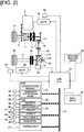
- Figure 2 illustrates the configuration of the control system of the front wheel drive based four-wheel drive vehicle to which is applied the clutch control device.
- the control system configuration of the four-wheel drive vehicle will be described below based on Figure 2 .
- the control system of the four-wheel drive vehicle is provided with an engine control module 31 (indicated “ECM” in Figure 2 ), a transmission control module 32 (indicated “TCM” in Figure 2 ), an ABS actuator control unit 33 (indicated “ABS actuator C/U” in Figure 2 ), and a 4WD control unit 34 (indicated “4WCC/U” in Figure 2 ), as illustrated in Figure 2 .
- ECM engine control module
- TCM transmission control module
- ABS actuator control unit 33 indicated “ABS actuator C/U” in Figure 2
- 4WD control unit 34 indicated “4WCC/U” in Figure 2
- the engine control module 31 is a control device of the transverse engine 1, which inputs detection signals from an engine rotational frequency sensor 35, an accelerator position opening amount sensor 36, and the like.
- Engine rotational frequency information and accelerator position opening amount information are input from this engine control module 31 to the 4WD control unit 34 via a CAN communication line 37.
- the transmission control module 32 is a control device of the transmission 2, which inputs detection signals from a transmission input rotational frequency sensor 38, the transmission output rotational frequency sensor 39, and the like. Gear ratio information (gear ratio information) is input from this transmission control module 32 to the 4WD control unit 34 via the CAN communication line 37.
- the ABS actuator control unit 33 is a control device of an ABS actuator (not shown) which controls the brake fluid pressure of each wheel, which inputs detection signals from a yaw rate sensor 40, a lateral G sensor 41, a longitudinal G sensor 42, wheel speed sensors 43, 44, 45, 46, and the like. Wheel speed information of each wheel, such as yaw rate information, lateral G information, and longitudinal G information, are inputted from this ABS actuator control unit 33 to the 4WD control unit 34 via the CAN communication line 37. Besides the information described above, steering angle information from a steering angle sensor 47 is input to the 4WD control unit 34 via the CAN communication line 37.
- the 4WD control unit 34 is a control device that controls the engagement and disengagement of the dog clutch 8 and the electronically controlled coupling 16, and carries out a calculation process based on various input information. That is, the 4WD control unit 34 corresponds to a clutch controller that carries out an engagement and disengagement control of the dog clutch 8 and an engagement and disengagement control of the electronically controlled coupling 16.
- this 4WD control unit 34 outputs drive control commands to a dog clutch actuator 48 (solenoid pin) and an electronically controlled coupling actuator 49 (electric motor).
- a drive mode selection switch 50 a brake switch 51 that detects the presence/absence of a braking operation, a ring gear rotational frequency sensor 52, a dog clutch stroke sensor 53, a motor rotation angle sensor 54, and the like are provided as input information sources from other than the CAN communication line 37.
- the drive mode selection switch 50 is a switch with which a driver switches to select among a "2WD mode,” a "lock mode,” and an “auto mode.”
- a driver switches to select among a "2WD mode,” a "lock mode,” and an "auto mode.”
- a front wheel drive 2WD state two-wheel drive travel
- the dog clutch 8 and the electronically controlled coupling 16 are released
- a full 4WD state four-wheel drive travel
- the engagement and disengagement of the dog clutch 8 and the electronically controlled coupling 16 is automatically controlled in accordance with the vehicle state (vehicle speed, accelerator position opening amount), and the drive mode is automatically switched.
- auto mode there is a choice between an “eco-auto mode,” which is selected when prioritizing improvement in fuel efficiency, and a “sports auto mode,” which is selected when prioritizing the four-wheel drive performance, and the state of the electronically controlled coupling 16 in a standby two-wheel drive mode in which the dog clutch 8 is engaged and the electronically controlled coupling 16 is released differs depending on the selected mode.
- the electronically controlled coupling 16 when the "eco-auto mode" is selected, the electronically controlled coupling 16 is put into a fully released state and waits during the standby two-wheel drive mode. At this time, the passage opening 25e is closed by the open/close valve 25d, and the lubrication oil is stored in the oil chamber 25c. In contrast, when the "sports auto mode” is selected, the electronically controlled coupling 16 is put into a released state immediately before engagement and waits during the standby two-wheel drive mode. At this time, the passage opening 25e is opened by the open/close valve 25d, and the lubrication oil flows into the clutch chamber 25b.
- the “fully released state” is a state in which the input-side clutch plate 16a and the output-side clutch plate 16c of the electronically controlled coupling 16 is separated, the two plates 16a, 16c do not come into contact immediately after the movable cam piston is moved to the clutch engaging side, and a clutch engagement capacity is not generated.
- the "released state immediately before engagement” is a state in which, while the clutch engagement capacity is zero, the input-side clutch plate 16a and the output-side clutch plate 16c are slightly in contact so that a clutch engagement capacity will be generated immediately if the movable cam piston is moved to the clutch engaging side even by a small amount.
- the ring gear rotational frequency sensor 52 is a sensor for acquiring output rotational speed information of the dog clutch 8, and which calculates the output side rotational frequency of the dog clutch 8 by taking into consideration the rear side gear ratio and the front side gear ratio upon calculation with respect to the detected value of the ring gear rotational frequency.
- the input rotational speed information of the dog clutch 8 is obtained by calculation using the engine rotational frequency, the gear ratio, and the final gear ratio.
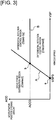
- Figure 3 illustrates a drive mode switching map corresponding to the vehicle speed and the accelerator position opening amount
- Figure 4 illustrates the switching transition of the drive mode (disconnected, two-wheel drive mode/standby two-wheel drive mode/connected, four-wheel drive mode), when the "auto mode" of the first embodiment is selected.
- the drive mode switching configuration will be described below, based on Figure 3 and Figure 4 .
- the drive mode when the "auto mode" is selected comprises a disconnected, two-wheel drive mode (Disconnect), a standby two-wheel drive mode (Standby), and a connected, four-wheel drive mode (Connect).
- These three drive modes are switched among each other by the 4WD control unit 34 on the basis of the vehicle speed (VSP), the accelerator position opening amount (ACC) which represents the requested drive force of the driver, and the drive mode switching map illustrated in Figure 3 .
- the drive mode switching map is set to be separated into the disconnected, two-wheel drive mode (referred to as “differential rotation control region (Disconnect)” in Figure 3 ), the standby two-wheel drive mode (referred to as “differential rotation control region (Standby)” in Figure 3 ), and connected, four-wheel drive mode (referred to as “drive force distribution region (Connect)” in Figure 3 ), in accordance with the vehicle speed and the accelerator position opening amount, as illustrated in Figure 3 .
- a region dividing line A (threshold vehicle speed) in which the accelerator position opening amount is increased proportionally with the increase in the vehicle speed from a base point a of a set vehicle speed VSP0 at which the accelerator position opening amount is zero
- a region dividing line B (threshold requested drive force) of a constant accelerator position opening amount ACC0, which is drawn from an intersection b with the region dividing line A toward the high vehicle speed side.
- the disconnected, two-wheel drive mode (differential rotation control region (Disconnect)) is set in the region in which the accelerator position opening amount is less than or equal to the set accelerator position opening amount ACC0, and which is surrounded by the vehicle speed axis line on which the accelerator position opening amount is zero, the region dividing line A, and the region dividing line B.
- the mode is set in a region in which, since the accelerator position opening amount is less than or equal to the set accelerator position opening amount ACC0 (the requested drive force of the driver is low) even in a high vehicle speed region, the frequency of occurrence of differential rotation of the left and right front wheels 6, 7 and the left and right rear wheels 19, 20 due to driving slip is extremely small, and even if driving slip occurs, the required four-wheel drive performance is low so that the slip is increased slowly.
- the standby two-wheel drive mode (differential rotation control region (Standby)) is set in the region in which the accelerator position opening amount exceeds the set accelerator position opening amount ACC0, and which is surrounded by the region dividing line A and the region dividing line B. That is, the mode is set in a region in which the accelerator position opening amount exceeds the set accelerator position opening amount ACC0 (the requested drive force of the driver is high) in a high vehicle speed region, while the required four-wheel drive performance is low, since if differential rotation of the left and right front wheels 6, 7 and the left and right rear wheels 19, 20 is generated due to driving slip, there is a high probability that the slip will increase rapidly.
- Standby differential rotation control region
- the connected, four-wheel drive mode (drive force distribution region (Connect)) is set in the region surrounded by the accelerator position opening amount axis line on which the vehicle speed is zero, the vehicle speed axis line on which the accelerator position opening amount is zero, and the region dividing line A. That is, the mode is set in a region in which the required four-wheel drive performance is high, such as when starting or during high-load travel in which the vehicle speed is low (low vehicle speed region) but the accelerator position opening amount is high.
- the travel mode becomes "2WD travel (Disconnect)" in which both the dog clutch 8 and the electronically controlled coupling 16 are released, as illustrated in frame C of Figure 4 .
- 2WD travel a front wheel drive two-wheel drive travel
- driving slip occurs in the left and right front wheels 6, 7 during a front wheel drive 2WD travel and the driving slip amount (or the driving slip rate) exceeds a threshold value, the electronically controlled coupling 16 is frictionally engaged.
- the travel mode becomes "2WD travel (Standby)" in which the dog clutch 8 is engaged and the electronically controlled coupling 16 is released, as illustrated in frame D of Figure 4 .
- the dog clutch 8 In this standby two-wheel drive mode, although the dog clutch 8 is engaged, basically a front wheel drive 2WD travel in which drive force is transmitted only to the left and right front wheels 6, 7 is maintained.
- driving slip occurs in the left and right front wheels 6, 7 during a front wheel drive 2WD travel and the driving slip amount (or the driving slip rate) exceeds a threshold value, only the electronically controlled coupling 16 is frictionally engaged, since the dog clutch 8 is engaged beforehand.
- Differential rotation control to suppress driving slip is carried out by allocating drive force to the left and right rear wheels 19, 20 with good responsiveness, by this frictional engagement of the electronically controlled coupling 16.
- the travel mode becomes "4WD travel (Connect)" in which both the dog clutch 8 and the electronically controlled coupling 16 are engaged, as illustrated in frame E of Figure 4 .
- drive force distribution control is carried out, which achieves the optimum drive force distribution to the left and right front wheels 6, 7 and to the left and right rear wheels 19, 20 that is suited to the road conditions (for example, distribution control to the front and rear wheels at the time of start).
- control is carried out in which the engagement capacity of the electronically controlled coupling 16 is decreased to reduce the possibility of a tight corner braking phenomenon.
- the switching transition between the disconnected, two-wheel drive mode (2WD travel (Disconnect)), the standby two-wheel drive mode (2WD travel (Standby)), and the connected, four-wheel drive mode (4WD travel (Connect)) is carried out by a switching request that is output when an operating point, which is determined by the vehicle speed and the accelerator position opening amount, crosses the region dividing line A and the region dividing line B, illustrated in Figure 3 .
- the switching transition speed of each drive mode is determined so that the transition speed to a drive mode that meets a 4WD request is prioritized over the transition speed to the disconnected, two-wheel drive mode that meets a fuel efficiency request.
- the switching transition speed of 2WD travel (Standby) - 2WD travel (Disconnect) (arrow G in Figure 4 ) is configured to be slower than the switching transition speed of 2WD travel (Disconnect) - 2WD travel (Standby) (arrow F in Figure 4 ).
- the switching transition speed of 4WD travel (Connect) - 2WD travel (Disconnect) (arrow I in Figure 4 ) is configured to be slower than the switching transition speed of 2WD travel (Disconnect) - 4WD travel (Connect) (arrow H in Figure 4 ).
- the switching transition speed of 4WD travel (Connect) - 2WD travel (Standby) is configured to be the same, relatively fast speed as the switching transition speed of 2WD travel (Standby) - 4WD travel (Connect) (arrow J in Figure 4 ).
- the "transition speed” is the time between an occurrence of a switching request and the completion of transition.
- this transition speed is slow (arrow G, arrow I)
- a mode transition control is started when a predetermined time has elapsed after a switching request is output.
- the transition speed is fast (arrow F, arrow H, arrow J, arrow K)
- a mode transition control is started immediately after a switching request is output.
- the passage opening 25e is closed by the open/close valve 25d provided to the coupling case 25, in conjunction with the disengagement control of the electronically controlled coupling 16.
- the lubrication oil that is moved from the clutch chamber 25b to the oil chamber 25c due to the centrifugal force generated by the rotation of the electronically controlled coupling 16 is stored in the oil chamber 25c.
- the amount of lubrication oil that is supplied to the electronically controlled coupling 16 housed in the clutch chamber 25b is limited, and the amount of lubrication oil in the clutch chamber 25b is reduced.
- the electronically controlled coupling 16 is engaged, even in the disconnected, two-wheel drive mode (2WD travel (Disconnect)). Accordingly, the passage opening 25e is opened by the open/close valve 25d in conjunction with this engagement control of the electronically controlled coupling 16. Then, the lubrication oil that is stored in the oil chamber 25c is made to flow from the oil chamber 25c to the clutch chamber 25b.
- Figure 5 is a flowchart illustrating the flow of the oil temperature control process that are executed in the 4WD control unit of the first embodiment. Each of the steps in Figure 5 , which represents the oil temperature control configuration process, will be described below.
- Step S1 it is determined whether or not the disconnected, two-wheel drive mode (2WD travel (Disconnect)) is selected as the current drive mode. If YES (disconnected, two-wheel drive mode selected), the process proceeds to Step S2. If NO (other than disconnected, two-wheel drive mode selected), the process proceeds to RETURN.
- the selected drive mode is determined based on the position of an operating point, which is determined by the vehicle speed and the accelerator position opening amount, on the drive mode switching map illustrated in Figure 3 . That is, if the operating point is in the disconnected, two-wheel drive mode region (region indicated by "differential rotation control region (Disconnect)" in Figure 3 ) on the drive mode switching map, it is determined that the disconnected, two-wheel drive mode is selected.
- the vehicle speed (VSP) is calculated from the wheel speed of the left and right rear wheels 19, 20, which are detected by the wheel speed sensors 45, 46.
- the accelerator position opening amount (ACC) is detected by the accelerator position opening amount sensor 36.
- both the dog clutch 8 and the electronically controlled coupling 16 are released. Furthermore, the passage opening 25e is closed by the open/close valve 25d that is provided to the coupling case 25, in conjunction with the disengagement control of the electronically controlled coupling 16. The lubrication oil is thereby stored in the oil chamber 25c, and the amount of lubrication oil that is supplied to the electronically controlled coupling 16 in the clutch chamber 25b is limited.
- Step S2 following the determination that the disconnected, two-wheel drive mode is selected in Step S1, it is determined whether or not the oil stirring conditions are met. If YES (oil stirring conditions are met), the process proceeds to Step S3. If NO (oil stirring conditions not met), the process proceeds to RETURN.
- the "oil stirring conditions” are conditions in which the temperature of the lubrication oil supplied to the electronically controlled coupling 16 (lubrication oil in the clutch chamber 25b) is determined to have been elevated above a predetermined threshold temperature.
- the disengagement time of the electronically controlled coupling 16 in the disconnected, two-wheel drive mode has reached a predetermined time.
- Step S3 following the determination that the oil stirring conditions are met in Step S2, an engagement command to fully engage the electronically controlled coupling 16 is output, and the process proceeds to Step S4.
- the movable cam piston is makes a stroke in the engagement direction by the electronically controlled coupling actuator 49, and the electronically controlled coupling 16 is placed in an engaged state.
- the passage opening 25e is opened by the open/close valve 25d in conjunction with the engagement control of the electronically controlled coupling 16.
- the lubrication oil in the oil chamber 25c thereby flows into the clutch chamber 25b via the passage opening 25e, and the amount of lubrication oil that is supplied to the electronically controlled coupling 16 in the clutch chamber 25b is increased.
- the lubrication oil that flows into the clutch chamber 25b is stirred by the rotation of the electronically controlled coupling 16, flows into the oil flow channel 25f due to the centrifugal force of this rotation, re-enters the oil chamber 25c, and circulates inside the coupling case 25.
- Step S4 following the output of the electronically controlled coupling engagement command in Step S3, it is determined whether or not oil stirring stop conditions are met. If YES (oil stirring stop conditions are met), the process proceeds to Step S5. If NO (oil stirring stop conditions are not met), the processs return to Step S3.
- the "oil stirring stop conditions” are conditions in which the temperature of the lubrication oil supplied to the electronically controlled coupling 16 (lubrication oil in the clutch chamber 25b) is determined to have decreased below a predetermined threshold temperature.
- the engagement time of the electronically controlled coupling in the disconnected, two-wheel drive mode has reached a predetermined time.
- Step S5 following the determination that the oil stirring stop conditions are met in Step S4, a disengagement command to fully disengage the electronically controlled coupling 16 is output, and the process proceeds to RETURN.
- the movable cam piston makes a stroke in the disengaging direction by the electronically controlled coupling actuator 49, and the electronically controlled coupling 16 is placed in a fully disengaged state.
- the passage opening 25e is opened by the open/close valve 25d in conjunction with the disengagement control of the electronically controlled coupling 16.
- the lubrication oil is thereby stored in the oil chamber 25c, and the amount of lubrication oil that is supplied to the electronically controlled coupling 16 in the clutch chamber 25b is again limited.
- Figure 6 is a time chart illustrating the features of the engagement capacity of the electronically controlled coupling and the engagement/disengagement states of the dog clutch, when switching from the connected, four-wheel drive mode to the disconnected, two-wheel drive mode in the first embodiment.
- Figure 7 is an explanatory view illustrating the flow of the lubrication oil when the oil stirring conditions are not met
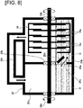
- Figure 8 is an explanatory view illustrating the flow of the lubrication oil when the oil stirring conditions are met, when in the disconnected, two-wheel drive mode of the first embodiment.
- the oil temperature control action of the first embodiment will be described below with reference to Figure 6- Figure 8 .
- a mode switch request is output at time t 1 , as shown in Figure 6 , to switch the drive mode from the connected, four-wheel drive mode to the disconnected, two-wheel drive mode
- a YES response is issued in Step S1 in the flowchart of Figure 5 , and, first, a disengagement command for fully releasing the electronically controlled coupling 16 is output.
- the clutch engagement capacity in the electronically controlled coupling 16 thereby starts to decrease.
- the clutch output shaft 16d of the electronically controlled coupling 16 is rotated together with the rotation of the left rear wheel 19. Accordingly, the lubrication oil O in the clutch chamber 25b is moved to the oil chamber 25c via the oil flow channel 25f by the centrifugal force generated by the rotation of the output side clutch plate 16c.
- the passage opening 25e of the coupling case 25 is closed by the open/close valve 25d, in conjunction with the disengagement control of the electronically controlled coupling 16, as illustrated in Figure 7 .
- the lubrication oil is thereby stored in the oil chamber 25c, and the amount of lubrication oil in the clutch chamber 25b that is supplied to the electronically controlled coupling 16 is limited.
- the lubrication oil in the oil chamber 25c leaks into the clutch chamber 25b via the axle bearing 25h that supports the clutch output shaft 16d, and the inflow amount at this time is less than the amount of lubrication oil that is moved from the clutch chamber 25b to the oil chamber 25c by centrifugal force. Accordingly, the amount of lubrication oil in the clutch chamber 25b will not increase. Then, if the amount of lubrication oil in the clutch chamber 25b falls below a predetermined amount, there will be no significant movement of lubrication oil into the oil chamber 25c.
- Step S 1 - Step S2 - Step S3 in the flowchart illustrated in Figure 5 , and an engagement command to fully engage the electronically controlled coupling 16 is output.
- the movable cam piston thereby makes a stroke in the engaging direction by the electronically controlled coupling actuator 49, and the electronically controlled coupling 16 is placed in an engaged state, as illustrated in Figure 8 . Furthermore, at this time, the passage opening 25e of the coupling case 25 is opened by the open/close valve 25d, in conjunction with the engagement control of the electronically controlled coupling 16.
- the lubrication oil O that is stored in the oil chamber 25c thereby flows into the clutch chamber 25b via the passage opening 25e.
- the lubrication oil O that is stored in the oil chamber 25c is stored without being stirred.
- the oil heating capacity is high. That is, the temperature of the lubrication oil O in the oil chamber 25c is relatively low compared to the lubrication oil O in the clutch chamber 25b.
- the input side clutch plate 16a and the output side clutch plate 16c will rotate integrally. Then, the lubrication oil O in the clutch chamber 25b is stirred by this rotation and flows into the oil flow channel 25f due to the centrifugal force generated by the rotation and re-enters the oil chamber 25c to circulate inside the coupling case 25.
- the lubrication oil O being stirred in the clutch chamber 25b in this manner, the lubrication oil O can circulate inside the coupling case 25, and it is possible to quickly reduce the lubrication oil temperature.
- the electronically controlled coupling 16 when the oil stirring conditions are met, the electronically controlled coupling 16 is fully engaged. Accordingly, it is possible to integrally rotate the input-side clutch plate 16a and the output-side clutch plate 16c in the electronically controlled coupling 16. It is thereby possible to maximize the oil stirring performance in the clutch chamber 25b, and to reduce the lubrication oil temperature more quickly.
- the open/close valve 25d maintains the passage opening 25e in the maximally open state. Accordingly, it is possible to maximize the amount of lubrication oil that flows from the oil chamber 25c into the clutch chamber 25b, and to reduce the lubrication oil temperature in the clutch chamber 25b as quickly as possible.
- the open/close valve 25d opens and closes the passage opening 25e in conjunction with the engagement and disengagement control of the electronically controlled coupling 16, it is possible to open and close the passage opening 25e with the open/close valve 25d, which does not require individual actuators or the like, and to control the lubrication oil temperature with a simple configuration.
- Step S4 - Step S5 in the flowchart illustrated in Figure 5 , and a disengagement command to fully disengage the electronically controlled coupling 16 is output.
- the movable cam piston thereby makes a stroke in the disengaging direction by the electronically controlled coupling actuator 49, and the electronically controlled coupling 16 is placed in a disengaged state, as illustrated in Figure 7 . Furthermore, at this time, the passage opening 25e of the coupling case 25 is closed by the open/close valve 25d, in conjunction with the disengagement control of the electronically controlled coupling 16.
- the lubrication oil O is again stored in the oil chamber 25c, and the lubrication oil amount in the clutch chamber 25b is regulated. Then, it is possible again to suppress the drag torque caused by the lubrication oil in the electronically controlled coupling 16, and to achieve an improvement in fuel efficiency.
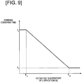
- the establishment of the oil stirring conditions which determine that the lubrication oil temperature in the clutch chamber 25b has been elevated, is set based on the "disengagement time of the electronically controlled coupling 16 when in the disconnected, two-wheel drive mode (hereinafter referred to as "stirring condition time"), and this stirring condition time is set in accordance with the estimated temperature of the lubrication oil in the clutch chamber 25b, as illustrated in Figure 9 .
- the stirring condition time is set to extend with the decline in the estimated temperature of the lubrication oil and the less the lubrication oil temperature becomes elevated.
- the stirring condition temperature is set to a maximum time ta.
- the stirring condition time will be set to a minimum time tb.
- the estimated temperature of the lubrication oil in the clutch chamber 25b is estimated on the basis of the vehicle speed, the travel distance, the clutch engagement capacity in the electronically controlled coupling 16, the differential rotation, and the like. Furthermore, the temperature may be directly detected by a temperature sensor provided to the coupling case 25.
- the clutch control device for a four-wheel drive vehicle of the present invention was described above based on the first embodiment, but specific configurations thereof are not limited to the first embodiment, and various modifications and additions to the design can be made without departing from the protective scope of the invention according to each claim in the Claims section.
- the dog clutch 8 is disposed in an upstream position (position between the transverse engine 1 and the bevel gear 9) of the bevel gear 9 provided at a drive branch position to the left and right rear wheels 19, 20, which are the auxiliary drive wheels, and in which the electronically controlled coupling 16 is disposed in a position of the left rear wheel drive shaft 17 from the bevel gear 9 to the left and right rear wheels 19, 20 via the propeller shaft 12 and the rear differential 15; however, the invention is not limited thereto.
- the dog clutch 8 may be disposed between the bevel gear 9 and the propeller shaft 12.
- the electronically controlled coupling 16 may be disposed in the position of the right rear wheel drive shaft 18, or disposed between the propeller shaft 12 and the rear differential 15.
- the dog clutch 8 may be configured form a dog clutch in which engagement and disengagement is carried out by a shift fork that is driven by hydraulic pressure.
- the electronically controlled coupling 16 may be configured from a hydraulic friction clutch that engages/disengages a multi-plate clutch by hydraulic pressure.
- the clutch control device for a four-wheel drive vehicle of the present invention is applied to a front wheel drive based four-wheel drive vehicle.
- the control device of the present invention may be applied to a rear wheel drive based four-wheel drive vehicle.
- the control device may be applied to a hybrid vehicle comprising an engine and a motor as drive sources, or to an electric vehicle comprising only a motor.
Landscapes
- Engineering & Computer Science (AREA)
- General Engineering & Computer Science (AREA)
- Mechanical Engineering (AREA)
- Physics & Mathematics (AREA)
- Fluid Mechanics (AREA)
- Chemical & Material Sciences (AREA)
- Combustion & Propulsion (AREA)
- Transportation (AREA)
- Arrangement And Mounting Of Devices That Control Transmission Of Motive Force (AREA)
- Arrangement And Driving Of Transmission Devices (AREA)
- Hydraulic Clutches, Magnetic Clutches, Fluid Clutches, And Fluid Joints (AREA)
- General Details Of Gearings (AREA)
Abstract
Description
- The present invention relates to a clutch control device for a four-wheel drive vehicle in which a system for transmitting drive force from the main drive wheels to the auxiliary drive wheels is provided with a dog clutch and a friction clutch.
- Conventionally, in a front wheel drive based four-wheel drive vehicle in which a system for transmitting drive force from the front wheels to the rear wheels is provided with a dog clutch and a friction clutch, a clutch control device that engages the dog clutch and the friction clutch during four-wheel drive travel and disengages the dog clutch and the friction clutch during two-wheel drive travel is known (for example, refer to Patent Document 1).
- In this clutch control device, a supply passage that supplies differential oil for lubricating the rear differential to the interior of the friction clutch, and a return passage that returns the differential oil supplied to the friction clutch to the rear differential, are formed. The differential oil is then scraped up by the rotation of the rear differential, and the differential oil is circulated from the supply passage to the friction clutch, then to the rear differential via the return passage.
- Patent Document 1: Japanese Laid Open Patent Application No.
2011-105256 - In a conventional device, the dog clutch and friction clutch are both released during two-wheel drive travel, and the differential oil passes through the supply passage and is circulated to the rear differential via the return passage. Consequently, drag torque is generated due to the resistance of the differential oil, and it is difficult to improve fuel efficiency.
- Therefore, a clutch control device for a four-wheel drive vehicle can be conceived in which improvement in fuel efficiency is achieved by limiting the amount of lubrication oil that is supplied to the friction clutch, when the friction clutch is released, to reduce the oil stirring resistance in the friction clutch.
- However, in this case, since the amount of lubrication oil that is supplied to the friction clutch is limited, the heat capacity of the lubrication oil is reduced. Consequently, there is the problem that the lubrication oil that is supplied to the friction clutch becomes hot.
- In view of the problems described above, an object of the present invention is to provide a clutch control device for a four-wheel drive vehicle capable of suppressing the increase in temperature of the lubrication oil that is supplied to a friction clutch, during two-wheel drive travel, when the friction clutch is released.
- In order to achieve the object above, the clutch control device for a four-wheel drive vehicle of the present invention is mounted on a four-wheel drive vehicle in which, of the left and right front wheels and the left and right rear wheels, one pair is set as the main drive wheels, which are connected to the drive source, and the other is set as the auxiliary drive wheels, which are connected to the drive source via a clutch, and is provided with a dog clutch, a friction clutch, and a clutch controller.
- The dog clutch is provided at a drive branch position from the main drive wheels to the auxiliary drive wheels, and separates the system for transmitting drive force to the auxiliary drive wheels from the system for transmitting drive force to the main drive wheels by releasing the clutch.
- The friction clutch is provided in a downstream position of the dog clutch, allocates a portion of the drive force from the drive source to the auxiliary drive wheels in accordance with the clutch engagement capacity, and is housed in a clutch case.
- The clutch controller carries out an engagement and disengagement control of the dog clutch and an engagement and disengagement control of the friction clutch.
- In this clutch control device for a four-wheel drive vehicle, the clutch case comprises a clutch chamber that houses the friction clutch, an oil chamber that is partitioned from the clutch chamber by a partition wall, an oil flow channel that places the clutch chamber in communication with the oil chamber and conveys lubrication oil from the clutch chamber to the oil chamber by the centrifugal force that is generated by the rotation of the friction clutch, and a passage opening provided in the partition wall that can be opened and closed.
- Then, when a disconnected, two-wheel drive mode is selected, which releases the dog clutch and the friction clutch, the clutch controller closes the passage opening and stores the lubrication oil in the oil chamber. In addition, after selecting the disconnected, two-wheel drive mode, when oil stirring conditions are met, in which the temperature of the lubrication oil in the clutch chamber is elevated, the clutch controller opens the passage opening and causes the lubrication oil to flow from the oil chamber to the clutch chamber.
- Therefore, in the clutch control device for a four-wheel drive vehicle of the present invention, when the disconnected, two-wheel drive mode which releases the dog clutch and the friction clutch is selected, the lubrication oil is stored in the oil chamber. Thereafter, when oil stirring conditions are met, in which the temperature of the lubrication oil that is supplied to the friction clutch and that remains in the clutch chamber is elevated, the clutch controller opens the passage opening and causes the lubrication oil to flow from the oil chamber to the clutch chamber in which the friction clutch is housed.
- Accordingly, even if the oil temperature in the clutch chamber is elevated, by causing lubrication oil stored in the oil chamber with a relatively low temperature to flow into the clutch chamber, it is possible to reduce the oil temperature in the clutch chamber.
- It is thereby possible to suppress the elevation of the temperature of the oil supplied to the friction clutch during two-wheel drive travel, when the friction clutch is released.
-
- [
Figure 1 ] is a block view of the drive system illustrating the configuration of the drive system of a front wheel drive based four-wheel drive vehicle to which is applied the clutch control device of the first embodiment. - [
Figure 2 ] is a block view of the control system illustrating the configuration of the control system of the front wheel drive based four-wheel drive vehicle to which is applied the clutch control device of the first embodiment. - [
Figure 3 ] is a basic map view illustrating a drive mode switching map corresponding to the vehicle speed and the accelerator position opening amount when the "auto mode" of the first embodiment is selected. - [
Figure 4 ] is a drive mode transition view illustrating the switching transition of the drive mode (disconnected, two-wheel drive mode/standby two-wheel drive mode/connected, four-wheel drive mode) when the "auto mode" of the first embodiment is selected. - [
Figure 5 ] is a flowchart illustrating the flow of the oil temperature control process that are executed in the 4WD control unit of the first embodiment. - [
Figure 6 ] is a time chart illustrating the features of the engagement capacity of the electronically controlled coupling and the engagement/disengagement states of the dog clutch, when switching from the connected, four-wheel drive mode to the disconnected, two-wheel drive mode in the first embodiment. - [
Figure 7 ] is an explanatory view illustrating the flow of the lubrication oil when the oil stirring conditions are not met when in the disconnected, two-wheel drive mode of the first embodiment. - [
Figure 8 ] is an explanatory view illustrating the flow of the lubrication oil when the oil stirring conditions are met when in the disconnected, two-wheel drive mode of the first embodiment. - [
Figure 9 ] is one example of a map illustrating the relationship between the stirring condition time and the estimated temperature of the lubrication oil in the first embodiment. - Embodiments for carrying out the clutch control device for a four-wheel drive vehicle of the present invention will be described below based on the first embodiment illustrated in the drawings.
- The configuration is described first.
- The "drive system configuration of the four-wheel drive vehicle," the "control system configuration of the four-wheel drive vehicle," the "drive mode switching configuration," and the "oil temperature control configuration process" will be separately described regarding the configuration of the clutch control device for a front wheel drive based four-wheel drive vehicle (one example of a four-wheel drive vehicle) in the first embodiment.
-
Figure 1 illustrates the configuration of the drive system of a front wheel drive based four-wheel drive vehicle to which is applied the clutch control device. The drive system configuration of the four-wheel drive vehicle will be described below based onFigure 1 . - The front wheel drive system of the four-wheel drive vehicle is provided with a transverse engine 1 (drive source), a
transmission 2, afront differential 3, a left frontwheel drive shaft 4, a right frontwheel drive shaft 5, a left front wheel 6 (main drive wheel), and a right front wheel 7 (main drive wheel), as illustrated inFigure 1 . That is, the drive force is transmitted from thetransverse engine 1 and thetransmission 2 to the left and right frontwheel drive shafts front differential 3, and constantly drives the left and rightfront wheels - The rear wheel drive system of the four-wheel drive vehicle comprises a dog clutch 8 (dog clutch), a
bevel gear 9, anoutput pinion 10, a rearwheel output shaft 11, apropeller shaft 12, adrive pinion 13, aring gear 14, arear differential 15, an electronically controlled coupling 16 (friction clutch), a left rearwheel drive shaft 17, a right rearwheel drive shaft 18, a left rear wheel 19 (auxiliary drive wheel), and a right rear wheel 20 (auxiliary drive wheel), as illustrated inFigure 1 . InFigure 1 , 21is a universal joint. - That is, the rear wheel drive system of the four-wheel drive vehicle is configured to be a drive system with which it is possible to select between two-wheel drive travel (= disconnected, two-wheel drive mode) in which the left and right
rear wheels transverse engine 1 by releasing both thedog clutch 8 and the electronically controlledcoupling 16, and four-wheel drive travel (= connected, four-wheel drive mode) in which the left and rightrear wheels transverse engine 1 by engaging both thedog clutch 8 and the electronically controlledcoupling 16. It is possible to stop the rotation of the drive system (rotation of thepropeller shaft 12, etc.) on the downstream side of the dog clutch 8 (between thedog clutch 8 and the left and rightrear wheels 19, 20) by releasing thisdog clutch 8, thereby suppressing friction loss and oil stirring loss to achieve improved fuel efficiency. - The
dog clutch 8 is a dog clutch that is provided at a drive branch position from the left and rightfront wheels rear wheels rear wheels front wheels dog clutch 8 is connected to the differential case of thefront differential 3, and the output side meshing member (not shown) of thedog clutch 8 is connected to thebevel gear 9. Thedog clutch 8, thebevel gear 9, theoutput pinion 10, and a portion of the rearwheel output shaft 11 are incorporated in atransfer case 23 that is fixed to a position adjacent to the frontdifferential case 22. For example, a dog clutch in which one of a pair of meshing members is a fixing member and the other is a movable member, a spring (not shown) that biases in the engaging direction is provided between the fixing member and the movable member, and a screw groove (not shown) that can be fitted with a solenoid pin (not shown) is formed on the outer perimeter of the movable member, is used as thisdog clutch 8. When the solenoid pin is projected and fitted to the screw groove, thisdog clutch 8 releases the engagement due to the movable member making a stroke in the releasing direction while being rotated and the stroke amount exceeding a predetermined amount. On the other hand, when the fitting of the solenoid pin with respect to the screw groove is disengaged, the movable member makes a stroke in the engaging direction toward the fixing member due to the biasing force of the spring, and the teeth of the two are meshed and engaged. - The electronically controlled
coupling 16 is a friction clutch that is provided in a downstream position of the dog clutch 8 (position between thedog clutch 8 and the auxiliary drive wheels, in this case, the left and rightrear wheels 19, 20), and that allocates a portion of the drive force from thetransverse engine 1 to the left and rightrear wheels side clutch plate 16a of the electronically controlledcoupling 16 is connected to a left side gear of therear differential 15 via aclutch input shaft 16b. The outputside clutch plate 16c of the electronically controlledcoupling 16 is connected to a left rearwheel drive shaft 17 via theclutch output shaft 16d. This electronically controlledcoupling 16 is incorporated in a coupling case 25 (clutch case) that is fixed in a position adjacent to a reardifferential case 24. - For example, a dog clutch comprising a multi-plate friction clutch in which multiple input-
side clutch plates 16a and output-side clutch plates 16c are alternately arranged, a fixed cam piston (not shown) and a movable cam piston (not shown) which have opposing cam surfaces, and a cam member (not shown) that is interposed between the opposing cam surfaces, is used as this electronically controlledcoupling 16. The engagement of the electronically controlledcoupling 16 is carried out by the movable cam piston being moved in the clutch engaging direction in accordance with the rotation angle to increase the frictional engagement force of the multi-plate friction clutch, due to a cam action that expands the piston gap that is generated by an electric motor (not shown) rotating the movable cam piston. The release of the electronically controlledcoupling 16 is carried out by the movable cam piston being moved in the clutch releasing direction in accordance with the rotation angle to decrease the frictional engagement force of the multi-plate friction clutch, due to a cam action that reduces the piston gap that is generated by the electric motor rotating the movable cam piston in the opposite direction of the engaging direction. - A
clutch chamber 25b and anoil chamber 25c are partitioned inside thecoupling case 25 by apartition wall 25a, as illustrated enlarged inFigure 1 . In addition, apassage opening 25e, which is openable and closable by an open/close valve 25d, is formed on thepartition wall 25a, thereby enabling the circulation of the lubrication oil that is enclosed in thecoupling case 25. In addition, theclutch chamber 25b and theoil chamber 25c are placed in communication with by anoil flow channel 25f. - The
clutch chamber 25b is a region for housing the electronically controlledcoupling 16 in thecoupling case 25. Theoil chamber 25c is a region in thecoupling case 25 in which lubrication oil is stored, which is moved from theclutch chamber 25b via theoil flow channel 25f by centrifugal force that is generated by the rotation of the electronically controlledcoupling 16. - The
passage opening 25e is a through-hole that is formed on thepartition wall 25a and places theclutch chamber 25b in communication with theoil chamber 25c. The open/close valve 25d opens and closes thepassage opening 25e in conjunction with the disengagement and engagement operation of the electronically controlledcoupling 16. - That is, the open/
close valve 25d can be linked with the movable cam piston and is driven in a direction to close thepassage opening 25e, when the movable cam piston makes a stroke in the clutch releasing direction. In addition, the valve is driven in a direction to open thepassage opening 25e when the movable cam piston is makes a stroke in the clutch engaging direction. Then, this open/close valve 25d closes thepassage opening 25e when the electronically controlledcoupling 16 is in a fully released state. In addition, when the movable cam piston is makes a stroke from a position that fully releases the electronically controlledcoupling 16 in the clutch engaging direction, thepassage opening 25e is gradually opened. Then, when the electronically controlledcoupling 16 is in a released state immediately before engagement, thepassage opening 25e is maximally opened, and when the electronically controlledcoupling 16 is engaged, the maximum open state of thepassage opening 25e is maintained. - The
oil flow channel 25f is a communication passage that constantly places theclutch chamber 25b in constant communication with theoil chamber 25c while bypassing thepartition wall 25a. Lubrication oil that has adhered to the inner surface of theclutch chamber 25b due to the centrifugal force accompanying the rotation of the electronically controlledcoupling 16 flows into thisoil flow channel 25f. Thisoil flow channel 25f is inclined toward theoil chamber 25c side so that the lubrication oil that has flowed in will flow into theoil chamber 25c. - The
clutch input shaft 16b extends through thecoupling case 25 and is inserted in theclutch chamber 25b. In addition, theclutch output shaft 16d extends through thecoupling case 25 and thepartition wall 25a, extends through theoil chamber 25c, and is inserted in theclutch chamber 25b. InFigure 1 , 25g is an oil seal and 25h is an axle bearing. Theoil seal 25g prevents the lubrication oil from leaking from thecoupling case 25 while rotatably supporting theclutch input shaft 16b and theclutch output shaft 16d. In addition, the axle bearing 25h allows circulation of the lubrication oil, and it is possible for the lubrication oil that is stored in theoil chamber 25c to constantly leak out to theclutch chamber 25b in small portions via the axle bearing 25h, even when thepassage opening 25e is closed by the open/close valve 25d. -
Figure 2 illustrates the configuration of the control system of the front wheel drive based four-wheel drive vehicle to which is applied the clutch control device. The control system configuration of the four-wheel drive vehicle will be described below based onFigure 2 . - The control system of the four-wheel drive vehicle is provided with an engine control module 31 (indicated "ECM" in
Figure 2 ), a transmission control module 32 (indicated "TCM" inFigure 2 ), an ABS actuator control unit 33 (indicated "ABS actuator C/U" inFigure 2 ), and a 4WD control unit 34 (indicated "4WCC/U" inFigure 2 ), as illustrated inFigure 2 . - The
engine control module 31 is a control device of thetransverse engine 1, which inputs detection signals from an enginerotational frequency sensor 35, an accelerator position openingamount sensor 36, and the like. Engine rotational frequency information and accelerator position opening amount information (ACC information) are input from thisengine control module 31 to the4WD control unit 34 via aCAN communication line 37. - The
transmission control module 32 is a control device of thetransmission 2, which inputs detection signals from a transmission inputrotational frequency sensor 38, the transmission outputrotational frequency sensor 39, and the like. Gear ratio information (gear ratio information) is input from thistransmission control module 32 to the4WD control unit 34 via theCAN communication line 37. - The ABS
actuator control unit 33 is a control device of an ABS actuator (not shown) which controls the brake fluid pressure of each wheel, which inputs detection signals from ayaw rate sensor 40, alateral G sensor 41, alongitudinal G sensor 42,wheel speed sensors actuator control unit 33 to the4WD control unit 34 via theCAN communication line 37. Besides the information described above, steering angle information from asteering angle sensor 47 is input to the4WD control unit 34 via theCAN communication line 37. - The
4WD control unit 34 is a control device that controls the engagement and disengagement of thedog clutch 8 and the electronically controlledcoupling 16, and carries out a calculation process based on various input information. That is, the4WD control unit 34 corresponds to a clutch controller that carries out an engagement and disengagement control of thedog clutch 8 and an engagement and disengagement control of the electronically controlledcoupling 16. - Then, this
4WD control unit 34 outputs drive control commands to a dog clutch actuator 48 (solenoid pin) and an electronically controlled coupling actuator 49 (electric motor). Here, a drivemode selection switch 50, abrake switch 51 that detects the presence/absence of a braking operation, a ring gearrotational frequency sensor 52, a dogclutch stroke sensor 53, a motorrotation angle sensor 54, and the like are provided as input information sources from other than theCAN communication line 37. - The drive
mode selection switch 50 is a switch with which a driver switches to select among a "2WD mode," a "lock mode," and an "auto mode." When the "2WD mode" is selected, a front wheel drive 2WD state (two-wheel drive travel) in which thedog clutch 8 and the electronically controlledcoupling 16 are released is maintained. When the "lock mode" is selected, a full 4WD state (four-wheel drive travel) in which thedog clutch 8 and the electronically controlledcoupling 16 are engaged is maintained. Furthermore, when the "auto mode" is selected, the engagement and disengagement of thedog clutch 8 and the electronically controlledcoupling 16 is automatically controlled in accordance with the vehicle state (vehicle speed, accelerator position opening amount), and the drive mode is automatically switched. - Here, in "auto mode" there is a choice between an "eco-auto mode," which is selected when prioritizing improvement in fuel efficiency, and a "sports auto mode," which is selected when prioritizing the four-wheel drive performance, and the state of the electronically controlled
coupling 16 in a standby two-wheel drive mode in which thedog clutch 8 is engaged and the electronically controlledcoupling 16 is released differs depending on the selected mode. - That is, when the "eco-auto mode" is selected, the electronically controlled
coupling 16 is put into a fully released state and waits during the standby two-wheel drive mode. At this time, thepassage opening 25e is closed by the open/close valve 25d, and the lubrication oil is stored in theoil chamber 25c. In contrast, when the "sports auto mode" is selected, the electronically controlledcoupling 16 is put into a released state immediately before engagement and waits during the standby two-wheel drive mode. At this time, thepassage opening 25e is opened by the open/close valve 25d, and the lubrication oil flows into theclutch chamber 25b. - This "eco-auto mode" and the "sports auto mode" are freely selected by the driver.
- The "fully released state" is a state in which the input-side
clutch plate 16a and the output-sideclutch plate 16c of the electronically controlledcoupling 16 is separated, the twoplates clutch plate 16a and the output-sideclutch plate 16c are slightly in contact so that a clutch engagement capacity will be generated immediately if the movable cam piston is moved to the clutch engaging side even by a small amount. - The ring gear
rotational frequency sensor 52 is a sensor for acquiring output rotational speed information of thedog clutch 8, and which calculates the output side rotational frequency of thedog clutch 8 by taking into consideration the rear side gear ratio and the front side gear ratio upon calculation with respect to the detected value of the ring gear rotational frequency. The input rotational speed information of thedog clutch 8 is obtained by calculation using the engine rotational frequency, the gear ratio, and the final gear ratio. -
Figure 3 illustrates a drive mode switching map corresponding to the vehicle speed and the accelerator position opening amount, andFigure 4 illustrates the switching transition of the drive mode (disconnected, two-wheel drive mode/standby two-wheel drive mode/connected, four-wheel drive mode), when the "auto mode" of the first embodiment is selected. The drive mode switching configuration will be described below, based onFigure 3 andFigure 4 . - In the first embodiment, the drive mode when the "auto mode" is selected comprises a disconnected, two-wheel drive mode (Disconnect), a standby two-wheel drive mode (Standby), and a connected, four-wheel drive mode (Connect). These three drive modes are switched among each other by the
4WD control unit 34 on the basis of the vehicle speed (VSP), the accelerator position opening amount (ACC) which represents the requested drive force of the driver, and the drive mode switching map illustrated inFigure 3 . - The drive mode switching map is set to be separated into the disconnected, two-wheel drive mode (referred to as "differential rotation control region (Disconnect)" in
Figure 3 ), the standby two-wheel drive mode (referred to as "differential rotation control region (Standby)" inFigure 3 ), and connected, four-wheel drive mode (referred to as "drive force distribution region (Connect)" inFigure 3 ), in accordance with the vehicle speed and the accelerator position opening amount, as illustrated inFigure 3 . - These three drive modes are separated by a region dividing line A (threshold vehicle speed) in which the accelerator position opening amount is increased proportionally with the increase in the vehicle speed from a base point a of a set vehicle speed VSP0 at which the accelerator position opening amount is zero, and a region dividing line B (threshold requested drive force) of a constant accelerator position opening amount ACC0, which is drawn from an intersection b with the region dividing line A toward the high vehicle speed side.
- The disconnected, two-wheel drive mode (differential rotation control region (Disconnect)) is set in the region in which the accelerator position opening amount is less than or equal to the set accelerator position opening amount ACC0, and which is surrounded by the vehicle speed axis line on which the accelerator position opening amount is zero, the region dividing line A, and the region dividing line B. That is, the mode is set in a region in which, since the accelerator position opening amount is less than or equal to the set accelerator position opening amount ACC0 (the requested drive force of the driver is low) even in a high vehicle speed region, the frequency of occurrence of differential rotation of the left and right
front wheels rear wheels - The standby two-wheel drive mode (differential rotation control region (Standby)) is set in the region in which the accelerator position opening amount exceeds the set accelerator position opening amount ACC0, and which is surrounded by the region dividing line A and the region dividing line B. That is, the mode is set in a region in which the accelerator position opening amount exceeds the set accelerator position opening amount ACC0 (the requested drive force of the driver is high) in a high vehicle speed region, while the required four-wheel drive performance is low, since if differential rotation of the left and right
front wheels rear wheels - The connected, four-wheel drive mode (drive force distribution region (Connect)) is set in the region surrounded by the accelerator position opening amount axis line on which the vehicle speed is zero, the vehicle speed axis line on which the accelerator position opening amount is zero, and the region dividing line A. That is, the mode is set in a region in which the required four-wheel drive performance is high, such as when starting or during high-load travel in which the vehicle speed is low (low vehicle speed region) but the accelerator position opening amount is high.
- When the disconnected, two-wheel drive mode is selected, the travel mode becomes "2WD travel (Disconnect)" in which both the
dog clutch 8 and the electronically controlledcoupling 16 are released, as illustrated in frame C ofFigure 4 . Basically, in this disconnected, two-wheel drive mode, a front wheel drive two-wheel drive travel (hereinafter referred to as "2WD travel") in which drive force is transmitted only to the left and rightfront wheels front wheels coupling 16 is frictionally engaged. Then, when a rotation synchronization state is determined, thedog clutch 8 is engaged to put into four-wheel drive travel (hereinafter referred to as "4WD travel"). Drive force is thereby allocated to the left and rightrear wheels - When the standby two-wheel drive mode is selected, the travel mode becomes "2WD travel (Standby)" in which the
dog clutch 8 is engaged and the electronically controlledcoupling 16 is released, as illustrated in frame D ofFigure 4 . In this standby two-wheel drive mode, although thedog clutch 8 is engaged, basically a front wheel drive 2WD travel in which drive force is transmitted only to the left and rightfront wheels front wheels coupling 16 is frictionally engaged, since thedog clutch 8 is engaged beforehand. Differential rotation control to suppress driving slip is carried out by allocating drive force to the left and rightrear wheels coupling 16. - When the connected, four-wheel drive mode is selected, the travel mode becomes "4WD travel (Connect)" in which both the
dog clutch 8 and the electronically controlledcoupling 16 are engaged, as illustrated in frame E ofFigure 4 . Basically, in this connected, four-wheel drive mode, drive force distribution control is carried out, which achieves the optimum drive force distribution to the left and rightfront wheels rear wheels steering angle sensor 47, theyaw rate sensor 40, thelateral G sensor 41, or thelongitudinal G sensor 42, control is carried out in which the engagement capacity of the electronically controlledcoupling 16 is decreased to reduce the possibility of a tight corner braking phenomenon. - The switching transition between the disconnected, two-wheel drive mode (2WD travel (Disconnect)), the standby two-wheel drive mode (2WD travel (Standby)), and the connected, four-wheel drive mode (4WD travel (Connect)) is carried out by a switching request that is output when an operating point, which is determined by the vehicle speed and the accelerator position opening amount, crosses the region dividing line A and the region dividing line B, illustrated in
Figure 3 . The switching transition speed of each drive mode is determined so that the transition speed to a drive mode that meets a 4WD request is prioritized over the transition speed to the disconnected, two-wheel drive mode that meets a fuel efficiency request. - That is, the switching transition speed of 2WD travel (Standby) - 2WD travel (Disconnect) (arrow G in
Figure 4 ) is configured to be slower than the switching transition speed of 2WD travel (Disconnect) - 2WD travel (Standby) (arrow F inFigure 4 ). Similarly, the switching transition speed of 4WD travel (Connect) - 2WD travel (Disconnect) (arrow I inFigure 4 ) is configured to be slower than the switching transition speed of 2WD travel (Disconnect) - 4WD travel (Connect) (arrow H inFigure 4 ). On the other hand, the switching transition speed of 4WD travel (Connect) - 2WD travel (Standby) (arrow K inFigure 4 ) is configured to be the same, relatively fast speed as the switching transition speed of 2WD travel (Standby) - 4WD travel (Connect) (arrow J inFigure 4 ). - In addition, the "transition speed" is the time between an occurrence of a switching request and the completion of transition. Here, when this transition speed is slow (arrow G, arrow I), a mode transition control is started when a predetermined time has elapsed after a switching request is output. In addition, when the transition speed is fast (arrow F, arrow H, arrow J, arrow K), a mode transition control is started immediately after a switching request is output.
- Furthermore, in this first embodiment, when selecting the disconnected, two-wheel drive mode, the
passage opening 25e is closed by the open/close valve 25d provided to thecoupling case 25, in conjunction with the disengagement control of the electronically controlledcoupling 16. The lubrication oil that is moved from theclutch chamber 25b to theoil chamber 25c due to the centrifugal force generated by the rotation of the electronically controlledcoupling 16 is stored in theoil chamber 25c. At this time, while the lubrication oil leaks from theoil chamber 25c to theclutch chamber 25b via the axle bearing 25h, the amount of lubrication oil that is supplied to the electronically controlledcoupling 16 housed in theclutch chamber 25b is limited, and the amount of lubrication oil in theclutch chamber 25b is reduced. - Then, when oil stirring conditions described below are met when in the disconnected, two-wheel drive mode (2WD travel (Disconnect)), the electronically controlled
coupling 16 is engaged, even in the disconnected, two-wheel drive mode (2WD travel (Disconnect)). Accordingly, thepassage opening 25e is opened by the open/close valve 25d in conjunction with this engagement control of the electronically controlledcoupling 16. Then, the lubrication oil that is stored in theoil chamber 25c is made to flow from theoil chamber 25c to theclutch chamber 25b. -
Figure 5 is a flowchart illustrating the flow of the oil temperature control process that are executed in the 4WD control unit of the first embodiment. Each of the steps inFigure 5 , which represents the oil temperature control configuration process, will be described below. - In Step S1, it is determined whether or not the disconnected, two-wheel drive mode (2WD travel (Disconnect)) is selected as the current drive mode. If YES (disconnected, two-wheel drive mode selected), the process proceeds to Step S2. If NO (other than disconnected, two-wheel drive mode selected), the process proceeds to RETURN.
- Here, the selected drive mode is determined based on the position of an operating point, which is determined by the vehicle speed and the accelerator position opening amount, on the drive mode switching map illustrated in
Figure 3 . That is, if the operating point is in the disconnected, two-wheel drive mode region (region indicated by "differential rotation control region (Disconnect)" inFigure 3 ) on the drive mode switching map, it is determined that the disconnected, two-wheel drive mode is selected. The vehicle speed (VSP) is calculated from the wheel speed of the left and rightrear wheels wheel speed sensors amount sensor 36. - Additionally, when the disconnected, two-wheel drive mode is selected, both the
dog clutch 8 and the electronically controlledcoupling 16 are released. Furthermore, thepassage opening 25e is closed by the open/close valve 25d that is provided to thecoupling case 25, in conjunction with the disengagement control of the electronically controlledcoupling 16. The lubrication oil is thereby stored in theoil chamber 25c, and the amount of lubrication oil that is supplied to the electronically controlledcoupling 16 in theclutch chamber 25b is limited. - In Step S2, following the determination that the disconnected, two-wheel drive mode is selected in Step S1, it is determined whether or not the oil stirring conditions are met. If YES (oil stirring conditions are met), the process proceeds to Step S3. If NO (oil stirring conditions not met), the process proceeds to RETURN.
- Here, the "oil stirring conditions" are conditions in which the temperature of the lubrication oil supplied to the electronically controlled coupling 16 (lubrication oil in the
clutch chamber 25b) is determined to have been elevated above a predetermined threshold temperature. Here, it is assumed that the disengagement time of the electronically controlledcoupling 16 in the disconnected, two-wheel drive mode has reached a predetermined time. - In Step S3, following the determination that the oil stirring conditions are met in Step S2, an engagement command to fully engage the electronically controlled
coupling 16 is output, and the process proceeds to Step S4. - Here, with the output of an engagement command of the electronically controlled
coupling 16, the movable cam piston is makes a stroke in the engagement direction by the electronically controlledcoupling actuator 49, and the electronically controlledcoupling 16 is placed in an engaged state. In addition, thepassage opening 25e is opened by the open/close valve 25d in conjunction with the engagement control of the electronically controlledcoupling 16. The lubrication oil in theoil chamber 25c thereby flows into theclutch chamber 25b via thepassage opening 25e, and the amount of lubrication oil that is supplied to the electronically controlledcoupling 16 in theclutch chamber 25b is increased. - Furthermore, the lubrication oil that flows into the
clutch chamber 25b is stirred by the rotation of the electronically controlledcoupling 16, flows into theoil flow channel 25f due to the centrifugal force of this rotation, re-enters theoil chamber 25c, and circulates inside thecoupling case 25. - In Step S4, following the output of the electronically controlled coupling engagement command in Step S3, it is determined whether or not oil stirring stop conditions are met. If YES (oil stirring stop conditions are met), the process proceeds to Step S5. If NO (oil stirring stop conditions are not met), the processs return to Step S3.
- Here, the "oil stirring stop conditions" are conditions in which the temperature of the lubrication oil supplied to the electronically controlled coupling 16 (lubrication oil in the
clutch chamber 25b) is determined to have decreased below a predetermined threshold temperature. Here, it is assumed that the engagement time of the electronically controlled coupling in the disconnected, two-wheel drive mode has reached a predetermined time. - In Step S5, following the determination that the oil stirring stop conditions are met in Step S4, a disengagement command to fully disengage the electronically controlled
coupling 16 is output, and the process proceeds to RETURN. - Here, with the output of the full disengagement command of the electronically controlled
coupling 16, the movable cam piston makes a stroke in the disengaging direction by the electronically controlledcoupling actuator 49, and the electronically controlledcoupling 16 is placed in a fully disengaged state. In addition, thepassage opening 25e is opened by the open/close valve 25d in conjunction with the disengagement control of the electronically controlledcoupling 16. The lubrication oil is thereby stored in theoil chamber 25c, and the amount of lubrication oil that is supplied to the electronically controlledcoupling 16 in theclutch chamber 25b is again limited. - Next, the "oil temperature control action" in the clutch control device for a four-wheel drive vehicle of the first embodiment will be described.
-
Figure 6 is a time chart illustrating the features of the engagement capacity of the electronically controlled coupling and the engagement/disengagement states of the dog clutch, when switching from the connected, four-wheel drive mode to the disconnected, two-wheel drive mode in the first embodiment. In addition,Figure 7 is an explanatory view illustrating the flow of the lubrication oil when the oil stirring conditions are not met, andFigure 8 is an explanatory view illustrating the flow of the lubrication oil when the oil stirring conditions are met, when in the disconnected, two-wheel drive mode of the first embodiment. The oil temperature control action of the first embodiment will be described below with reference toFigure 6-Figure 8 . - If a mode switch request is output at time t1, as shown in
Figure 6 , to switch the drive mode from the connected, four-wheel drive mode to the disconnected, two-wheel drive mode, a YES response is issued in Step S1 in the flowchart ofFigure 5 , and, first, a disengagement command for fully releasing the electronically controlledcoupling 16 is output. The clutch engagement capacity in the electronically controlledcoupling 16 thereby starts to decrease. - When the clutch engagement capacity in the electronically controlled
coupling 16 becomes zero and the electronically controlledcoupling 16 if fully disengaged at time t2, thedog clutch 8 is subsequently disengaged. Both thedog clutch 8 and the electronically controlledcoupling 16 are thereby placed in a disengaged state. - In addition, at this time, the
clutch output shaft 16d of the electronically controlledcoupling 16 is rotated together with the rotation of the leftrear wheel 19. Accordingly, the lubrication oil O in theclutch chamber 25b is moved to theoil chamber 25c via theoil flow channel 25f by the centrifugal force generated by the rotation of the output sideclutch plate 16c. On the other hand, the passage opening 25e of thecoupling case 25 is closed by the open/close valve 25d, in conjunction with the disengagement control of the electronically controlledcoupling 16, as illustrated inFigure 7 . - The lubrication oil is thereby stored in the
oil chamber 25c, and the amount of lubrication oil in theclutch chamber 25b that is supplied to the electronically controlledcoupling 16 is limited. The lubrication oil in theoil chamber 25c leaks into theclutch chamber 25b via the axle bearing 25h that supports theclutch output shaft 16d, and the inflow amount at this time is less than the amount of lubrication oil that is moved from theclutch chamber 25b to theoil chamber 25c by centrifugal force. Accordingly, the amount of lubrication oil in theclutch chamber 25b will not increase. Then, if the amount of lubrication oil in theclutch chamber 25b falls below a predetermined amount, there will be no significant movement of lubrication oil into theoil chamber 25c. In other words, if the amount of lubrication oil that leaks into theclutch chamber 25b via the axle bearing 25h and the amount of lubrication oil that moves into theoil chamber 25c due to the centrifugal force reach equilibrium, the amount of lubrication oil in theclutch chamber 25b is stabilized at a small amount. - In addition, by regulating the amount of lubrication oil in the
clutch chamber 25b when in the disconnected, two-wheel drive mode in this manner, even if theclutch output shaft 16d and the output sideclutch plate 16c are rotated together with the leftrear wheel 19, the drag torque caused by the lubrication oil in the electronically controlledcoupling 16 can be suppressed. Accordingly, it is possible to achieve an improvement in fuel efficiency. - However, since the amount of lubrication oil that remains in the
clutch chamber 25b and supplied to the electronically controlledcoupling 16 is small, the oil heating capacity in theclutch chamber 25b is also small. Consequently, since there is no contact between the input-sideclutch plate 16a and the output-sideclutch plate 16c of the electronically controlledcoupling 16, the lubrication oil temperature between the twoplates - Thus, when the oil stirring conditions are met at time t3, due to a predetermined time having elapsed from time t2, at which point the temperature of the lubrication oil in the
clutch chamber 25b can be determined to have been elevated, the process proceeds to Step S 1 - Step S2 - Step S3 in the flowchart illustrated inFigure 5 , and an engagement command to fully engage the electronically controlledcoupling 16 is output. - The movable cam piston thereby makes a stroke in the engaging direction by the electronically controlled
coupling actuator 49, and the electronically controlledcoupling 16 is placed in an engaged state, as illustrated inFigure 8 . Furthermore, at this time, the passage opening 25e of thecoupling case 25 is opened by the open/close valve 25d, in conjunction with the engagement control of the electronically controlledcoupling 16. - The lubrication oil O that is stored in the
oil chamber 25c thereby flows into theclutch chamber 25b via thepassage opening 25e. Here, the lubrication oil O that is stored in theoil chamber 25c is stored without being stirred. Additionally, since there is a large amount of lubrication oil, the oil heating capacity is high. That is, the temperature of the lubrication oil O in theoil chamber 25c is relatively low compared to the lubrication oil O in theclutch chamber 25b. - Then, as a result of the lubrication oil O in the
oil chamber 25c with a relatively low temperature flowing into theclutch chamber 25b, low temperature lubrication oil O is added to high temperature lubrication oil O, and it becomes possible to reduce the temperature of the lubrication oil O in theclutch chamber 25b. In addition, since the amount of lubrication oil in theclutch chamber 25b increases, the oil heating capacity in theclutch chamber 25b can be increased, and it becomes possible to suppress an elevation in the temperature of the lubrication oil O that is supplied to the electronically controlledcoupling 16. As a result, it becomes possible to suppress an elevation in the temperature of the lubrication oil O that is supplied to the electronically controlled coupling 16 (lubrication oil O in theclutch chamber 25b), and to control the oil temperature to an appropriate temperature. - Additionally, with the engagement of the electronically controlled
coupling 16, the input sideclutch plate 16a and the output sideclutch plate 16c will rotate integrally. Then, the lubrication oil O in theclutch chamber 25b is stirred by this rotation and flows into theoil flow channel 25f due to the centrifugal force generated by the rotation and re-enters theoil chamber 25c to circulate inside thecoupling case 25. - As a result of the lubrication oil O being stirred in the
clutch chamber 25b in this manner, the lubrication oil O can circulate inside thecoupling case 25, and it is possible to quickly reduce the lubrication oil temperature. - Furthermore, in this first embodiment, when the oil stirring conditions are met, the electronically controlled
coupling 16 is fully engaged. Accordingly, it is possible to integrally rotate the input-sideclutch plate 16a and the output-sideclutch plate 16c in the electronically controlledcoupling 16. It is thereby possible to maximize the oil stirring performance in theclutch chamber 25b, and to reduce the lubrication oil temperature more quickly. - Moreover, here, when the electronically controlled
coupling 16 is fully engaged, the open/close valve 25d maintains thepassage opening 25e in the maximally open state. Accordingly, it is possible to maximize the amount of lubrication oil that flows from theoil chamber 25c into theclutch chamber 25b, and to reduce the lubrication oil temperature in theclutch chamber 25b as quickly as possible. - Additionally, since the open/
close valve 25d opens and closes thepassage opening 25e in conjunction with the engagement and disengagement control of the electronically controlledcoupling 16, it is possible to open and close thepassage opening 25e with the open/close valve 25d, which does not require individual actuators or the like, and to control the lubrication oil temperature with a simple configuration. - Then, when the oil stirring stop conditions are met at time t4, due to a predetermined time having elapsed from time t3, at which point the temperature of the lubrication oil in the
clutch chamber 25b can be determined to have decreased, the process proceeds to Step S4 - Step S5 in the flowchart illustrated inFigure 5 , and a disengagement command to fully disengage the electronically controlledcoupling 16 is output. - The movable cam piston thereby makes a stroke in the disengaging direction by the electronically controlled
coupling actuator 49, and the electronically controlledcoupling 16 is placed in a disengaged state, as illustrated inFigure 7 . Furthermore, at this time, the passage opening 25e of thecoupling case 25 is closed by the open/close valve 25d, in conjunction with the disengagement control of the electronically controlledcoupling 16. - Accordingly, the lubrication oil O is again stored in the
oil chamber 25c, and the lubrication oil amount in theclutch chamber 25b is regulated. Then, it is possible again to suppress the drag torque caused by the lubrication oil in the electronically controlledcoupling 16, and to achieve an improvement in fuel efficiency. - When the oil stirring conditions are met again after time t5 when the electronically controlled
coupling 16 is fully disengaged, the electronically controlledcoupling 16 is reengaged, and the lubrication oil O is circulated from theoil chamber 25c to theclutch chamber 25b to reduce the oil temperature in theclutch chamber 25b by stirring the lubrication oil O. In addition, when the oil stirring stop conditions are met, the electronically controlledcoupling 16 is disengaged and the lubrication oil O is stored in theoil chamber 25c to achieve an improvement in fuel efficiency. - In this manner, it is possible to carry out an oil temperature control to prevent the lubrication oil O that remains in the
clutch chamber 25b and supplied to the electronically controlledcoupling 16 from reaching a high temperature while the disconnected, two-wheel drive mode continues to be selected, by repeating engagement and disengagement of the electronically controlledcoupling 16. - The establishment of the oil stirring conditions, which determine that the lubrication oil temperature in the
clutch chamber 25b has been elevated, is set based on the "disengagement time of the electronically controlledcoupling 16 when in the disconnected, two-wheel drive mode (hereinafter referred to as "stirring condition time"), and this stirring condition time is set in accordance with the estimated temperature of the lubrication oil in theclutch chamber 25b, as illustrated inFigure 9 . - That is, the stirring condition time is set to extend with the decline in the estimated temperature of the lubrication oil and the less the lubrication oil temperature becomes elevated. Here, when the estimated temperature of the lubrication oil is less than or equal to a lower limit temperature Tα, the stirring condition temperature is set to a maximum time ta. In addition, when the estimated temperature of the lubrication oil is greater than or equal to an upper limit temperature Tβ, the stirring condition time will be set to a minimum time tb.
- In addition, the estimated temperature of the lubrication oil in the
clutch chamber 25b is estimated on the basis of the vehicle speed, the travel distance, the clutch engagement capacity in the electronically controlledcoupling 16, the differential rotation, and the like. Furthermore, the temperature may be directly detected by a temperature sensor provided to thecoupling case 25. - Next, the effects are described.
- The effects listed below can be obtained with the clutch control device for a four-wheel drive vehicle according to the first embodiment.
- (1) A clutch control device for a four-wheel drive vehicle mounted in a four-wheel drive vehicle, in which, of the left and right
front wheels rear wheels front wheels 6, 7) to the auxiliary drive wheels (left and rightrear wheels 19, 20), and separates a system for transmitting drive force (rear wheel drive system) to the auxiliary drive wheels (left and rightrear wheels 19, 20) from a system for transmitting drive force (front wheel drive system) to the main drive wheels (left and rightfront wheels 6, 7) by releasing the clutch,
a friction clutch (electronically controlled coupling 16) provided in a downstream position of the dog clutch (dog clutch 8) which allocates a portion of the drive force from the drive source (transverse engine 1) to the auxiliary drive wheels (left and rightrear wheels 19, 20) in accordance with the clutch engagement capacity, and which is housed in a clutch case (coupling case 25), and
a clutch controller (4WD control unit 34) that carries out an engagement and disengagement control of the dog clutch (dog clutch 8) and an engagement and disengagement control of the friction clutch (electronically controlled coupling 16),
wherein
the clutch case (coupling case 25) comprises aclutch chamber 25b that houses the friction clutch (electronically controlled coupling 16), anoil chamber 25c that is partitioned from theclutch chamber 25b by apartition wall 25a, anoil flow channel 25f that places theclutch chamber 25b in communication with theoil chamber 25c and flows lubrication oil O from theclutch chamber 25b to theoil chamber 25c due to the centrifugal force that is generated by a rotation of the friction clutch (electronically controlled coupling 16), and apassage opening 25e provided in thepartition wall 25a that can be opened and closed, and wherein
when a disconnected, two-wheel drive mode which releases the dog clutch (dog clutch 8) and the friction clutch (electronically controlled coupling 16) is selected, the clutch controller (4WD control unit 34) closes thepassage opening 25e and stores the lubrication oil O in theoil chamber 25c, and after the disconnected, two-wheel drive mode is selected, when oil stirring conditions, in which the temperature of the lubrication oil in theclutch chamber 25b is elevated, are met, the clutch controller opens thepassage opening 25e and causes the lubrication oil O to flow from theoil chamber 25c to theclutch chamber 25b.
It is thereby possible to suppress an elevation of the temperature of the lubrication oil supplied to the friction clutch (electronically controlled coupling 16) during two-wheel drive travel with the friction clutch (electronically controlled coupling 16) released. - (2) The clutch controller (4WD control unit 34) is configured to engage the friction clutch (electronically controlled coupling 16) when the oil stirring conditions are met.
Accordingly, in addition to the effect of (1) above, it is possible to stir the lubrication oil O in theclutch chamber 25b and circulate the lubrication oil O inside thecoupling case 25, to quickly reduce the lubrication oil temperature. - (3) The clutch controller (4WD control unit 34) is configured to put the friction clutch (electronically controlled coupling 16) in a fully engaged state, when the oil stirring conditions are met.
Accordingly, in addition to the effect of (2) above, it is possible to maximize the oil stirring performance in theclutch chamber 25b, and to reduce the lubrication oil temperature more quickly. - (4) An open/
close valve 25d that opens and closes thepassage opening 25e is provided in thepartition wall 25a, and
the open/close valve 25d drives thepassage opening 25e in a closing direction in conjunction with a stroke of the friction clutch (electronically controlled coupling 16) in the disengagement direction, and drives thepassage opening 25e in an opening direction in conjunction with a stroke of the friction clutch (electronically controlled coupling 16) in the engagement direction.
Accordingly, in addition to the effects of (2) and (3) above, it is possible to open and close thepassage opening 25e with the open/close valve 25d, which does not require individual actuators or the like, and to control the lubrication oil temperature with a simple configuration. - (5) The clutch controller (4WD control unit 34) is configured to close the
passage opening 25e and store the lubrication oil O in theoil chamber 25c, when oil stirring stop conditions are met, in which the lubrication oil temperature in theclutch chamber 25b has decreased, after the establishment of the oil stirring conditions.
Accordingly, in addition to any one of the effects of (1)-(4) above, after the establishment of the oil stirring stop conditions, the lubrication oil O is stored in theoil chamber 25c again, and the amount of lubrication oil in the clutch 25b is regulated. Therefore, it is possible to suppress the drag torque by the lubrication oil and to achieve an improvement in fuel efficiency. - The clutch control device for a four-wheel drive vehicle of the present invention was described above based on the first embodiment, but specific configurations thereof are not limited to the first embodiment, and various modifications and additions to the design can be made without departing from the protective scope of the invention according to each claim in the Claims section.
- In the first embodiment, an example was shown in which the
dog clutch 8 is disposed in an upstream position (position between thetransverse engine 1 and the bevel gear 9) of thebevel gear 9 provided at a drive branch position to the left and rightrear wheels coupling 16 is disposed in a position of the left rearwheel drive shaft 17 from thebevel gear 9 to the left and rightrear wheels propeller shaft 12 and the rear differential 15; however, the invention is not limited thereto. - For example, the
dog clutch 8 may be disposed between thebevel gear 9 and thepropeller shaft 12. In addition, the electronically controlledcoupling 16 may be disposed in the position of the right rearwheel drive shaft 18, or disposed between thepropeller shaft 12 and therear differential 15. - Furthermore, the
dog clutch 8 may be configured form a dog clutch in which engagement and disengagement is carried out by a shift fork that is driven by hydraulic pressure. Additionally, the electronically controlledcoupling 16 may be configured from a hydraulic friction clutch that engages/disengages a multi-plate clutch by hydraulic pressure. - In the first embodiment, an example was shown in which the clutch control device for a four-wheel drive vehicle of the present invention is applied to a front wheel drive based four-wheel drive vehicle. However, the control device of the present invention may be applied to a rear wheel drive based four-wheel drive vehicle. Additionally, the control device may be applied to a hybrid vehicle comprising an engine and a motor as drive sources, or to an electric vehicle comprising only a motor.
- This application claims right of priority based on Japanese Patent Application No.
2014-036741
Claims (5)
- A clutch control device for a four-wheel drive vehicle mounted in a four-wheel drive vehicle, in which, of the left and right front wheels and the left and right rear wheels, one pair is set as the main drive wheels, which are connected to a drive source, and the other is set as the auxiliary drive wheels, which are connected to the drive source via a clutch, comprising:a dog clutch provided at a drive branch position from the main drive wheels to the auxiliary drive wheels, which separates a system for transmitting drive force to the auxiliary drive wheels from a system for transmitting drive force to the main drive wheels by releasing the clutch;a friction clutch provided in a downstream position of the dog clutch, which allocates a portion of the drive force from the drive source to the auxiliary drive wheels in accordance with a clutch engagement capacity, and which is housed in a clutch case; anda clutch controller that carries out an engagement and disengagement control of the dog clutch and an engagement and disengagement control of the friction clutch, whereinthe clutch case comprises a clutch chamber that houses the friction clutch, an oil chamber that is partitioned from the clutch chamber by a partition wall, an oil flow channel that places the clutch chamber in communication with the oil chamber and conveys lubrication oil from the clutch chamber to the oil chamber by a centrifugal force that is generated by a rotation of the friction clutch, and a passage opening provided in the partition wall that can be opened and closed, and
wherein, when a disconnected, two-wheel drive mode which releases the dog clutch and the friction clutch is selected, the clutch controller closes the passage opening and stores the lubrication oil in the oil chamber; after selecting the disconnected, two-wheel drive mode, when oil stirring conditions are met, in which the temperature of the lubrication oil in the clutch chamber is elevated, the clutch controller opens the passage opening and causes the lubrication oil to flow from the oil chamber to the clutch chamber. - The clutch control device for a four-wheel drive vehicle as recited in claim 1, wherein the clutch controller engages the friction clutch when the oil stirring conditions are met.
- The clutch control device for a four-wheel drive vehicle as recited in claim 2, wherein
the clutch controller puts the friction clutch into a fully engaged state when the oil stirring conditions are met. - The clutch control device for a four-wheel drive vehicle as recited in claim 2 or claim 3, wherein
an open/close valve that opens and closes the passage opening is provided in the partition wall, and
the open/close valve drives the passage opening in a closing direction in conjunction with a stroke of the friction clutch in the disengaging direction, and drives the passage opening in an opening direction in conjunction with a stroke of the friction clutch in the engaging direction. - The clutch control device for a four-wheel drive vehicle as recited in any one of claims 1 to 4, wherein
the clutch controller closes the passage opening and stores the lubrication oil in the oil chamber when oil stirring stop conditions are met, in which the lubrication oil temperature in the clutch chamber has decreased, after the establishment of the oil stirring conditions.
Applications Claiming Priority (2)
| Application Number | Priority Date | Filing Date | Title |
|---|---|---|---|
| JP2014036741 | 2014-02-27 | ||
| PCT/JP2015/053032 WO2015129410A1 (en) | 2014-02-27 | 2015-02-04 | Clutch control device for four-wheel drive vehicle |
Publications (3)
| Publication Number | Publication Date |
|---|---|
| EP3112726A1 true EP3112726A1 (en) | 2017-01-04 |
| EP3112726A4 EP3112726A4 (en) | 2017-04-12 |
| EP3112726B1 EP3112726B1 (en) | 2018-08-22 |
Family
ID=54008736
Family Applications (1)
| Application Number | Title | Priority Date | Filing Date |
|---|---|---|---|
| EP15756056.6A Not-in-force EP3112726B1 (en) | 2014-02-27 | 2015-02-04 | Clutch control device for four-wheel drive vehicle |
Country Status (5)
| Country | Link |
|---|---|
| US (1) | US9688141B2 (en) |
| EP (1) | EP3112726B1 (en) |
| JP (1) | JP6183535B2 (en) |
| CN (1) | CN106062426B (en) |
| WO (1) | WO2015129410A1 (en) |
Cited By (1)
| Publication number | Priority date | Publication date | Assignee | Title |
|---|---|---|---|---|
| EP3561334A1 (en) * | 2018-04-23 | 2019-10-30 | Toyota Jidosha Kabushiki Kaisha | Four-wheel drive vehicle |
Families Citing this family (15)
| Publication number | Priority date | Publication date | Assignee | Title |
|---|---|---|---|---|
| US8042642B2 (en) * | 2008-08-14 | 2011-10-25 | American Axle & Manufacturing, Inc. | Motor vehicle with disconnectable all-wheel drive system |
| WO2015156161A1 (en) * | 2014-04-11 | 2015-10-15 | 日産自動車株式会社 | Clutch control device for four-wheel-drive vehicle |
| CA2917373A1 (en) * | 2016-01-12 | 2017-07-12 | 2Low | Two wheel drive low range devices and systems |
| JP6394627B2 (en) * | 2016-03-09 | 2018-09-26 | トヨタ自動車株式会社 | Lubrication device for engagement mechanism |
| JP6686660B2 (en) * | 2016-04-15 | 2020-04-22 | 株式会社ジェイテクト | Driving force transmission device |
| JP6926220B2 (en) * | 2017-03-03 | 2021-08-25 | ジーケーエヌ オートモーティブ リミテッド | How and equipment to operate the drivetrain |
| JP2019006173A (en) * | 2017-06-21 | 2019-01-17 | 株式会社ジェイテクト | Auxiliary drive |
| US10207582B2 (en) * | 2017-06-30 | 2019-02-19 | Shaeffler Technologies Ag & Co. Kg | Differential assembly with clutch |
| US10774883B2 (en) | 2018-06-06 | 2020-09-15 | Borgwarner Inc. | Passive wet clutch lube valve with a bailing system and transmission including the same |
| SE1850961A1 (en) * | 2018-08-08 | 2019-10-01 | C Falk Remote Control Ab | Torque-limiting clutch comprising an electric control system |
| US10927937B2 (en) | 2018-09-06 | 2021-02-23 | American Axle & Manufacturing, Inc. | Modular disconnecting drive module with torque vectoring augmentation |
| US10704663B2 (en) | 2018-09-06 | 2020-07-07 | American Axle & Manufacturing, Inc. | Modular disconnecting drive module with torque vectoring augmentation |
| CN112234770B (en) * | 2019-07-15 | 2022-01-14 | 华为技术有限公司 | Oil-cooled motor control device and method |
| JP7079755B2 (en) * | 2019-09-03 | 2022-06-02 | 本田技研工業株式会社 | Vehicle drive |
| CN111791869B (en) * | 2019-10-31 | 2021-10-08 | 长城汽车股份有限公司 | A kind of intelligent four-wheel drive control method, system and vehicle |
Family Cites Families (15)
| Publication number | Priority date | Publication date | Assignee | Title |
|---|---|---|---|---|
| JP2007285459A (en) * | 2006-04-18 | 2007-11-01 | Gkn ドライブライン トルクテクノロジー株式会社 | Lubrication structure of power transmission device |
| JP5260080B2 (en) * | 2008-02-25 | 2013-08-14 | 株式会社ユニバンス | Driving force transmission device for four-wheel drive vehicles |
| JP2009243577A (en) * | 2008-03-31 | 2009-10-22 | Univance Corp | Driving force distribution device |
| US8215440B2 (en) | 2008-05-06 | 2012-07-10 | Getrag Driveline Systems, Gmbh | Drive train for a vehicle with connectable secondary axle |
| US8388486B2 (en) * | 2009-08-11 | 2013-03-05 | Magna Powertrain Of America, Inc. | AWD vehicle with active disconnect coupling having multi-stage ball ramp |
| JP2011105256A (en) | 2009-11-20 | 2011-06-02 | Toyota Motor Corp | Power transmission device |
| JP5083371B2 (en) * | 2010-05-10 | 2012-11-28 | トヨタ自動車株式会社 | Four-wheel drive vehicle control system |
| JP5728861B2 (en) | 2010-09-15 | 2015-06-03 | 株式会社ジェイテクト | Four-wheel drive vehicle and its control device |
| JP5720165B2 (en) * | 2010-10-05 | 2015-05-20 | 株式会社ジェイテクト | Four-wheel drive vehicle |
| CN103442922B (en) * | 2011-03-31 | 2016-03-30 | 株式会社捷太格特 | Drive force distribution control device and four-wheel drive vehicles |
| EP2701936B1 (en) * | 2011-04-28 | 2020-03-11 | Jaguar Land Rover Limited | Vehicle and method of controlling a vehicle, power transfer unit and method of controlling a power transfer unit |
| JP5958261B2 (en) | 2011-10-19 | 2016-07-27 | 株式会社ジェイテクト | Driving force transmission device |
| JP2013132996A (en) * | 2011-12-26 | 2013-07-08 | Aisin Aw Co Ltd | Vehicle drive device |
| US9688142B2 (en) * | 2014-02-27 | 2017-06-27 | Nissan Motor Co., Ltd. | Clutch control device for 4-wheel drive vehicle |
| JP6064972B2 (en) * | 2014-10-16 | 2017-01-25 | トヨタ自動車株式会社 | Control device for four-wheel drive device for vehicle |
-
2015
- 2015-02-04 EP EP15756056.6A patent/EP3112726B1/en not_active Not-in-force
- 2015-02-04 CN CN201580009261.2A patent/CN106062426B/en not_active Expired - Fee Related
- 2015-02-04 JP JP2016505123A patent/JP6183535B2/en not_active Expired - Fee Related
- 2015-02-04 US US15/117,822 patent/US9688141B2/en not_active Expired - Fee Related
- 2015-02-04 WO PCT/JP2015/053032 patent/WO2015129410A1/en not_active Ceased
Cited By (3)
| Publication number | Priority date | Publication date | Assignee | Title |
|---|---|---|---|---|
| EP3561334A1 (en) * | 2018-04-23 | 2019-10-30 | Toyota Jidosha Kabushiki Kaisha | Four-wheel drive vehicle |
| KR20190123231A (en) * | 2018-04-23 | 2019-10-31 | 도요타 지도샤(주) | Four wheel drive vehicle |
| US11072238B2 (en) | 2018-04-23 | 2021-07-27 | Toyota Jidosha Kabushiki Kaisha | Four-wheel drive vehicle |
Also Published As
| Publication number | Publication date |
|---|---|
| US20170008396A1 (en) | 2017-01-12 |
| CN106062426A (en) | 2016-10-26 |
| EP3112726B1 (en) | 2018-08-22 |
| CN106062426B (en) | 2017-10-13 |
| WO2015129410A1 (en) | 2015-09-03 |
| JP6183535B2 (en) | 2017-08-23 |
| US9688141B2 (en) | 2017-06-27 |
| EP3112726A4 (en) | 2017-04-12 |
| JPWO2015129410A1 (en) | 2017-03-30 |
Similar Documents
| Publication | Publication Date | Title |
|---|---|---|
| EP3112726B1 (en) | Clutch control device for four-wheel drive vehicle | |
| JP6168232B2 (en) | Clutch control device for four-wheel drive vehicle | |
| US9688142B2 (en) | Clutch control device for 4-wheel drive vehicle | |
| US9845006B2 (en) | Clutch control device for 4-wheel drive vehicle | |
| US9783053B2 (en) | Clutch control device for 4-wheel drive vehicle | |
| US20150362052A1 (en) | Transmission and hydraulic control system | |
| US11499626B2 (en) | System and method for changing to a low gear range of a four wheel drive vehicle | |
| JP6123942B2 (en) | Clutch control device for four-wheel drive vehicle | |
| US10899351B2 (en) | Hybrid powertrain system and operation with transfer case in low gear | |
| JP2013015216A (en) | Shift control method of vehicle with automatic manual transmission | |
| CN107444384B (en) | Method for operating a vehicle automatic start/stop system using a fluid launch clutch | |
| KR20260051432A (en) | Control method and device for a hybrid vehicle and its dual-motor hybrid system | |
| RU2644492C1 (en) | Adaptive control device for starting vehicle clutch | |
| US11913543B2 (en) | Method and transmission control apparatus for operating a multiple-speed vehicle transmission | |
| WO2018123306A1 (en) | Control device | |
| CN110056648B (en) | Transmission control | |
| JP6194815B2 (en) | Transfer device for four-wheel drive vehicles | |
| Chiew et al. | Performance of proportional control in CVT Electro-Mechanical Clutch | |
| JP2015017624A (en) | Lubricator for vehicles |
Legal Events
| Date | Code | Title | Description |
|---|---|---|---|
| PUAI | Public reference made under article 153(3) epc to a published international application that has entered the european phase |
Free format text: ORIGINAL CODE: 0009012 |
|
| STAA | Information on the status of an ep patent application or granted ep patent |
Free format text: STATUS: REQUEST FOR EXAMINATION WAS MADE |
|
| 17P | Request for examination filed |
Effective date: 20160912 |
|
| AK | Designated contracting states |
Kind code of ref document: A1 Designated state(s): AL AT BE BG CH CY CZ DE DK EE ES FI FR GB GR HR HU IE IS IT LI LT LU LV MC MK MT NL NO PL PT RO RS SE SI SK SM TR |
|
| AX | Request for extension of the european patent |
Extension state: BA ME |
|
| A4 | Supplementary search report drawn up and despatched |
Effective date: 20170315 |
|
| RIC1 | Information provided on ipc code assigned before grant |
Ipc: B60K 23/08 20060101ALI20170309BHEP Ipc: F16H 57/04 20100101AFI20170309BHEP Ipc: B60K 17/348 20060101ALI20170309BHEP Ipc: F16D 48/02 20060101ALI20170309BHEP Ipc: F16D 25/12 20060101ALI20170309BHEP Ipc: F16D 13/72 20060101ALI20170309BHEP |
|
| DAX | Request for extension of the european patent (deleted) | ||
| STAA | Information on the status of an ep patent application or granted ep patent |
Free format text: STATUS: EXAMINATION IS IN PROGRESS |
|
| 17Q | First examination report despatched |
Effective date: 20170926 |
|
| GRAP | Despatch of communication of intention to grant a patent |
Free format text: ORIGINAL CODE: EPIDOSNIGR1 |
|
| STAA | Information on the status of an ep patent application or granted ep patent |
Free format text: STATUS: GRANT OF PATENT IS INTENDED |
|
| INTG | Intention to grant announced |
Effective date: 20180426 |
|
| GRAS | Grant fee paid |
Free format text: ORIGINAL CODE: EPIDOSNIGR3 |
|
| GRAA | (expected) grant |
Free format text: ORIGINAL CODE: 0009210 |
|
| STAA | Information on the status of an ep patent application or granted ep patent |
Free format text: STATUS: THE PATENT HAS BEEN GRANTED |
|
| AK | Designated contracting states |
Kind code of ref document: B1 Designated state(s): AL AT BE BG CH CY CZ DE DK EE ES FI FR GB GR HR HU IE IS IT LI LT LU LV MC MK MT NL NO PL PT RO RS SE SI SK SM TR |
|
| REG | Reference to a national code |
Ref country code: GB Ref legal event code: FG4D |
|
| REG | Reference to a national code |
Ref country code: CH Ref legal event code: EP |
|
| REG | Reference to a national code |
Ref country code: AT Ref legal event code: REF Ref document number: 1032907 Country of ref document: AT Kind code of ref document: T Effective date: 20180915 |
|
| REG | Reference to a national code |
Ref country code: IE Ref legal event code: FG4D |
|
| REG | Reference to a national code |
Ref country code: DE Ref legal event code: R096 Ref document number: 602015015176 Country of ref document: DE |
|
| REG | Reference to a national code |
Ref country code: NL Ref legal event code: MP Effective date: 20180822 |
|
| REG | Reference to a national code |
Ref country code: LT Ref legal event code: MG4D |
|
| PG25 | Lapsed in a contracting state [announced via postgrant information from national office to epo] |
Ref country code: GR Free format text: LAPSE BECAUSE OF FAILURE TO SUBMIT A TRANSLATION OF THE DESCRIPTION OR TO PAY THE FEE WITHIN THE PRESCRIBED TIME-LIMIT Effective date: 20181123 Ref country code: SE Free format text: LAPSE BECAUSE OF FAILURE TO SUBMIT A TRANSLATION OF THE DESCRIPTION OR TO PAY THE FEE WITHIN THE PRESCRIBED TIME-LIMIT Effective date: 20180822 Ref country code: NL Free format text: LAPSE BECAUSE OF FAILURE TO SUBMIT A TRANSLATION OF THE DESCRIPTION OR TO PAY THE FEE WITHIN THE PRESCRIBED TIME-LIMIT Effective date: 20180822 Ref country code: BG Free format text: LAPSE BECAUSE OF FAILURE TO SUBMIT A TRANSLATION OF THE DESCRIPTION OR TO PAY THE FEE WITHIN THE PRESCRIBED TIME-LIMIT Effective date: 20181122 Ref country code: IS Free format text: LAPSE BECAUSE OF FAILURE TO SUBMIT A TRANSLATION OF THE DESCRIPTION OR TO PAY THE FEE WITHIN THE PRESCRIBED TIME-LIMIT Effective date: 20181222 Ref country code: RS Free format text: LAPSE BECAUSE OF FAILURE TO SUBMIT A TRANSLATION OF THE DESCRIPTION OR TO PAY THE FEE WITHIN THE PRESCRIBED TIME-LIMIT Effective date: 20180822 Ref country code: NO Free format text: LAPSE BECAUSE OF FAILURE TO SUBMIT A TRANSLATION OF THE DESCRIPTION OR TO PAY THE FEE WITHIN THE PRESCRIBED TIME-LIMIT Effective date: 20181122 Ref country code: FI Free format text: LAPSE BECAUSE OF FAILURE TO SUBMIT A TRANSLATION OF THE DESCRIPTION OR TO PAY THE FEE WITHIN THE PRESCRIBED TIME-LIMIT Effective date: 20180822 Ref country code: LT Free format text: LAPSE BECAUSE OF FAILURE TO SUBMIT A TRANSLATION OF THE DESCRIPTION OR TO PAY THE FEE WITHIN THE PRESCRIBED TIME-LIMIT Effective date: 20180822 |
|
| REG | Reference to a national code |
Ref country code: AT Ref legal event code: MK05 Ref document number: 1032907 Country of ref document: AT Kind code of ref document: T Effective date: 20180822 |
|
| PG25 | Lapsed in a contracting state [announced via postgrant information from national office to epo] |
Ref country code: AL Free format text: LAPSE BECAUSE OF FAILURE TO SUBMIT A TRANSLATION OF THE DESCRIPTION OR TO PAY THE FEE WITHIN THE PRESCRIBED TIME-LIMIT Effective date: 20180822 Ref country code: LV Free format text: LAPSE BECAUSE OF FAILURE TO SUBMIT A TRANSLATION OF THE DESCRIPTION OR TO PAY THE FEE WITHIN THE PRESCRIBED TIME-LIMIT Effective date: 20180822 Ref country code: HR Free format text: LAPSE BECAUSE OF FAILURE TO SUBMIT A TRANSLATION OF THE DESCRIPTION OR TO PAY THE FEE WITHIN THE PRESCRIBED TIME-LIMIT Effective date: 20180822 |
|
| PG25 | Lapsed in a contracting state [announced via postgrant information from national office to epo] |
Ref country code: PL Free format text: LAPSE BECAUSE OF FAILURE TO SUBMIT A TRANSLATION OF THE DESCRIPTION OR TO PAY THE FEE WITHIN THE PRESCRIBED TIME-LIMIT Effective date: 20180822 Ref country code: ES Free format text: LAPSE BECAUSE OF FAILURE TO SUBMIT A TRANSLATION OF THE DESCRIPTION OR TO PAY THE FEE WITHIN THE PRESCRIBED TIME-LIMIT Effective date: 20180822 Ref country code: CZ Free format text: LAPSE BECAUSE OF FAILURE TO SUBMIT A TRANSLATION OF THE DESCRIPTION OR TO PAY THE FEE WITHIN THE PRESCRIBED TIME-LIMIT Effective date: 20180822 Ref country code: RO Free format text: LAPSE BECAUSE OF FAILURE TO SUBMIT A TRANSLATION OF THE DESCRIPTION OR TO PAY THE FEE WITHIN THE PRESCRIBED TIME-LIMIT Effective date: 20180822 Ref country code: IT Free format text: LAPSE BECAUSE OF FAILURE TO SUBMIT A TRANSLATION OF THE DESCRIPTION OR TO PAY THE FEE WITHIN THE PRESCRIBED TIME-LIMIT Effective date: 20180822 Ref country code: EE Free format text: LAPSE BECAUSE OF FAILURE TO SUBMIT A TRANSLATION OF THE DESCRIPTION OR TO PAY THE FEE WITHIN THE PRESCRIBED TIME-LIMIT Effective date: 20180822 Ref country code: AT Free format text: LAPSE BECAUSE OF FAILURE TO SUBMIT A TRANSLATION OF THE DESCRIPTION OR TO PAY THE FEE WITHIN THE PRESCRIBED TIME-LIMIT Effective date: 20180822 |
|
| REG | Reference to a national code |
Ref country code: DE Ref legal event code: R097 Ref document number: 602015015176 Country of ref document: DE |
|
| PG25 | Lapsed in a contracting state [announced via postgrant information from national office to epo] |
Ref country code: SK Free format text: LAPSE BECAUSE OF FAILURE TO SUBMIT A TRANSLATION OF THE DESCRIPTION OR TO PAY THE FEE WITHIN THE PRESCRIBED TIME-LIMIT Effective date: 20180822 Ref country code: SM Free format text: LAPSE BECAUSE OF FAILURE TO SUBMIT A TRANSLATION OF THE DESCRIPTION OR TO PAY THE FEE WITHIN THE PRESCRIBED TIME-LIMIT Effective date: 20180822 Ref country code: DK Free format text: LAPSE BECAUSE OF FAILURE TO SUBMIT A TRANSLATION OF THE DESCRIPTION OR TO PAY THE FEE WITHIN THE PRESCRIBED TIME-LIMIT Effective date: 20180822 |
|
| PLBE | No opposition filed within time limit |
Free format text: ORIGINAL CODE: 0009261 |
|
| STAA | Information on the status of an ep patent application or granted ep patent |
Free format text: STATUS: NO OPPOSITION FILED WITHIN TIME LIMIT |
|
| 26N | No opposition filed |
Effective date: 20190523 |
|
| PG25 | Lapsed in a contracting state [announced via postgrant information from national office to epo] |
Ref country code: SI Free format text: LAPSE BECAUSE OF FAILURE TO SUBMIT A TRANSLATION OF THE DESCRIPTION OR TO PAY THE FEE WITHIN THE PRESCRIBED TIME-LIMIT Effective date: 20180822 |
|
| REG | Reference to a national code |
Ref country code: CH Ref legal event code: PL |
|
| PG25 | Lapsed in a contracting state [announced via postgrant information from national office to epo] |
Ref country code: MC Free format text: LAPSE BECAUSE OF FAILURE TO SUBMIT A TRANSLATION OF THE DESCRIPTION OR TO PAY THE FEE WITHIN THE PRESCRIBED TIME-LIMIT Effective date: 20180822 Ref country code: LU Free format text: LAPSE BECAUSE OF NON-PAYMENT OF DUE FEES Effective date: 20190204 |
|
| REG | Reference to a national code |
Ref country code: BE Ref legal event code: MM Effective date: 20190228 |
|
| REG | Reference to a national code |
Ref country code: IE Ref legal event code: MM4A |
|
| PG25 | Lapsed in a contracting state [announced via postgrant information from national office to epo] |
Ref country code: CH Free format text: LAPSE BECAUSE OF NON-PAYMENT OF DUE FEES Effective date: 20190228 Ref country code: LI Free format text: LAPSE BECAUSE OF NON-PAYMENT OF DUE FEES Effective date: 20190228 |
|
| PG25 | Lapsed in a contracting state [announced via postgrant information from national office to epo] |
Ref country code: IE Free format text: LAPSE BECAUSE OF NON-PAYMENT OF DUE FEES Effective date: 20190204 |
|
| PG25 | Lapsed in a contracting state [announced via postgrant information from national office to epo] |
Ref country code: BE Free format text: LAPSE BECAUSE OF NON-PAYMENT OF DUE FEES Effective date: 20190228 |
|
| PG25 | Lapsed in a contracting state [announced via postgrant information from national office to epo] |
Ref country code: TR Free format text: LAPSE BECAUSE OF FAILURE TO SUBMIT A TRANSLATION OF THE DESCRIPTION OR TO PAY THE FEE WITHIN THE PRESCRIBED TIME-LIMIT Effective date: 20180822 |
|
| PG25 | Lapsed in a contracting state [announced via postgrant information from national office to epo] |
Ref country code: PT Free format text: LAPSE BECAUSE OF FAILURE TO SUBMIT A TRANSLATION OF THE DESCRIPTION OR TO PAY THE FEE WITHIN THE PRESCRIBED TIME-LIMIT Effective date: 20181222 Ref country code: MT Free format text: LAPSE BECAUSE OF NON-PAYMENT OF DUE FEES Effective date: 20190204 |
|
| PGFP | Annual fee paid to national office [announced via postgrant information from national office to epo] |
Ref country code: FR Payment date: 20201210 Year of fee payment: 7 |
|
| PG25 | Lapsed in a contracting state [announced via postgrant information from national office to epo] |
Ref country code: CY Free format text: LAPSE BECAUSE OF FAILURE TO SUBMIT A TRANSLATION OF THE DESCRIPTION OR TO PAY THE FEE WITHIN THE PRESCRIBED TIME-LIMIT Effective date: 20180822 |
|
| PGFP | Annual fee paid to national office [announced via postgrant information from national office to epo] |
Ref country code: DE Payment date: 20210119 Year of fee payment: 7 Ref country code: GB Payment date: 20210127 Year of fee payment: 7 |
|
| PG25 | Lapsed in a contracting state [announced via postgrant information from national office to epo] |
Ref country code: HU Free format text: LAPSE BECAUSE OF FAILURE TO SUBMIT A TRANSLATION OF THE DESCRIPTION OR TO PAY THE FEE WITHIN THE PRESCRIBED TIME-LIMIT; INVALID AB INITIO Effective date: 20150204 |
|
| PG25 | Lapsed in a contracting state [announced via postgrant information from national office to epo] |
Ref country code: MK Free format text: LAPSE BECAUSE OF FAILURE TO SUBMIT A TRANSLATION OF THE DESCRIPTION OR TO PAY THE FEE WITHIN THE PRESCRIBED TIME-LIMIT Effective date: 20180822 |
|
| REG | Reference to a national code |
Ref country code: DE Ref legal event code: R119 Ref document number: 602015015176 Country of ref document: DE |
|
| GBPC | Gb: european patent ceased through non-payment of renewal fee |
Effective date: 20220204 |
|
| PG25 | Lapsed in a contracting state [announced via postgrant information from national office to epo] |
Ref country code: FR Free format text: LAPSE BECAUSE OF NON-PAYMENT OF DUE FEES Effective date: 20220228 |
|
| PG25 | Lapsed in a contracting state [announced via postgrant information from national office to epo] |
Ref country code: GB Free format text: LAPSE BECAUSE OF NON-PAYMENT OF DUE FEES Effective date: 20220204 Ref country code: DE Free format text: LAPSE BECAUSE OF NON-PAYMENT OF DUE FEES Effective date: 20220901 |