EP3112606A1 - A seal for a gas turbine engine - Google Patents
A seal for a gas turbine engine Download PDFInfo
- Publication number
- EP3112606A1 EP3112606A1 EP16177836.0A EP16177836A EP3112606A1 EP 3112606 A1 EP3112606 A1 EP 3112606A1 EP 16177836 A EP16177836 A EP 16177836A EP 3112606 A1 EP3112606 A1 EP 3112606A1
- Authority
- EP
- European Patent Office
- Prior art keywords
- shield
- seal
- gas turbine
- turbine engine
- vane
- Prior art date
- Legal status (The legal status is an assumption and is not a legal conclusion. Google has not performed a legal analysis and makes no representation as to the accuracy of the status listed.)
- Granted
Links
- 230000003068 static effect Effects 0.000 claims description 11
- 238000011144 upstream manufacturing Methods 0.000 claims description 10
- 238000000034 method Methods 0.000 claims description 3
- 239000000446 fuel Substances 0.000 description 5
- 230000009467 reduction Effects 0.000 description 2
- 230000008901 benefit Effects 0.000 description 1
- 230000008859 change Effects 0.000 description 1
- 238000002485 combustion reaction Methods 0.000 description 1
- 238000004891 communication Methods 0.000 description 1
- 230000006835 compression Effects 0.000 description 1
- 238000007906 compression Methods 0.000 description 1
- 238000004519 manufacturing process Methods 0.000 description 1
- 230000007246 mechanism Effects 0.000 description 1
- 238000012986 modification Methods 0.000 description 1
- 230000004048 modification Effects 0.000 description 1
- 230000004044 response Effects 0.000 description 1
Images
Classifications
-
- F—MECHANICAL ENGINEERING; LIGHTING; HEATING; WEAPONS; BLASTING
- F01—MACHINES OR ENGINES IN GENERAL; ENGINE PLANTS IN GENERAL; STEAM ENGINES
- F01D—NON-POSITIVE DISPLACEMENT MACHINES OR ENGINES, e.g. STEAM TURBINES
- F01D11/00—Preventing or minimising internal leakage of working-fluid, e.g. between stages
- F01D11/08—Preventing or minimising internal leakage of working-fluid, e.g. between stages for sealing space between rotor blade tips and stator
-
- F—MECHANICAL ENGINEERING; LIGHTING; HEATING; WEAPONS; BLASTING
- F01—MACHINES OR ENGINES IN GENERAL; ENGINE PLANTS IN GENERAL; STEAM ENGINES
- F01D—NON-POSITIVE DISPLACEMENT MACHINES OR ENGINES, e.g. STEAM TURBINES
- F01D11/00—Preventing or minimising internal leakage of working-fluid, e.g. between stages
- F01D11/001—Preventing or minimising internal leakage of working-fluid, e.g. between stages for sealing space between stator blade and rotor
-
- F—MECHANICAL ENGINEERING; LIGHTING; HEATING; WEAPONS; BLASTING
- F01—MACHINES OR ENGINES IN GENERAL; ENGINE PLANTS IN GENERAL; STEAM ENGINES
- F01D—NON-POSITIVE DISPLACEMENT MACHINES OR ENGINES, e.g. STEAM TURBINES
- F01D11/00—Preventing or minimising internal leakage of working-fluid, e.g. between stages
- F01D11/005—Sealing means between non relatively rotating elements
-
- F—MECHANICAL ENGINEERING; LIGHTING; HEATING; WEAPONS; BLASTING
- F01—MACHINES OR ENGINES IN GENERAL; ENGINE PLANTS IN GENERAL; STEAM ENGINES
- F01D—NON-POSITIVE DISPLACEMENT MACHINES OR ENGINES, e.g. STEAM TURBINES
- F01D11/00—Preventing or minimising internal leakage of working-fluid, e.g. between stages
- F01D11/08—Preventing or minimising internal leakage of working-fluid, e.g. between stages for sealing space between rotor blade tips and stator
- F01D11/12—Preventing or minimising internal leakage of working-fluid, e.g. between stages for sealing space between rotor blade tips and stator using a rubstrip, e.g. erodible. deformable or resiliently-biased part
- F01D11/122—Preventing or minimising internal leakage of working-fluid, e.g. between stages for sealing space between rotor blade tips and stator using a rubstrip, e.g. erodible. deformable or resiliently-biased part with erodable or abradable material
-
- F—MECHANICAL ENGINEERING; LIGHTING; HEATING; WEAPONS; BLASTING
- F01—MACHINES OR ENGINES IN GENERAL; ENGINE PLANTS IN GENERAL; STEAM ENGINES
- F01D—NON-POSITIVE DISPLACEMENT MACHINES OR ENGINES, e.g. STEAM TURBINES
- F01D25/00—Component parts, details, or accessories, not provided for in, or of interest apart from, other groups
- F01D25/24—Casings; Casing parts, e.g. diaphragms, casing fastenings
- F01D25/246—Fastening of diaphragms or stator-rings
-
- F—MECHANICAL ENGINEERING; LIGHTING; HEATING; WEAPONS; BLASTING
- F01—MACHINES OR ENGINES IN GENERAL; ENGINE PLANTS IN GENERAL; STEAM ENGINES
- F01D—NON-POSITIVE DISPLACEMENT MACHINES OR ENGINES, e.g. STEAM TURBINES
- F01D9/00—Stators
- F01D9/02—Nozzles; Nozzle boxes; Stator blades; Guide conduits, e.g. individual nozzles
- F01D9/04—Nozzles; Nozzle boxes; Stator blades; Guide conduits, e.g. individual nozzles forming ring or sector
- F01D9/042—Nozzles; Nozzle boxes; Stator blades; Guide conduits, e.g. individual nozzles forming ring or sector fixing blades to stators
-
- F—MECHANICAL ENGINEERING; LIGHTING; HEATING; WEAPONS; BLASTING
- F02—COMBUSTION ENGINES; HOT-GAS OR COMBUSTION-PRODUCT ENGINE PLANTS
- F02C—GAS-TURBINE PLANTS; AIR INTAKES FOR JET-PROPULSION PLANTS; CONTROLLING FUEL SUPPLY IN AIR-BREATHING JET-PROPULSION PLANTS
- F02C7/00—Features, components parts, details or accessories, not provided for in, or of interest apart form groups F02C1/00 - F02C6/00; Air intakes for jet-propulsion plants
- F02C7/28—Arrangement of seals
Definitions
- a gas turbine engine typically includes a fan section, a compressor section, a combustor section, and a turbine section. Air entering the compressor section is compressed and delivered into the combustion section where it is mixed with fuel and ignited to generate a high-speed exhaust gas flow. The high-speed exhaust gas flow expands through the turbine section to drive the compressor and the fan section.
- a gas turbine engine assembly in one exemplary embodiment, includes a shield that has a first portion and a second portion.
- the first portion extends radially from an axial end portion of the shield and includes a blade outer air seal contact surface.
- the second portion extends axially from a radially outer end of the first portion and includes a vane contact surface.
- the shield forms a complete unitary circumferential hoop.
- the shield forms a circumferential hoop with a single discontinuity.
- a seal is in contact with the shield.
- the second portion of the shield is located radially outward from the seal.
- the first portion of the shield is located axially upstream from the seal.
- the seal includes a "W" shaped cross section pointing radially outward.
- the second portion of the shield is located radially outward from the seal and the first portion of the shield is located axially downstream from the seal.
- a gas turbine engine in another exemplary embodiment, includes at least one vane. At least one blade outer air seal is adjacent at least one vane. A shield is located axially between the at least one vane and the at least one blade outer air seal. A seal is located radially inward from the shield.
- the shield comprises a first portion that extends radially on an axially upstream end of the shield.
- the shield comprises a first portion that extends radially on an axially downstream end of the shield.
- the shield comprises a second portion that extends axially from a radially outer end of the first portion.
- the second portion of the shield is located radially outward from the seal.
- the first portion of the shield is located axially upstream from the seal.
- At least one vane includes at least one anti-rotation tab
- At least one blade outer air seal includes a feature for engaging at least one anti-rotation tab.
- an engine static structure has a plurality anti-rotation protrusions and at least one anti-rotation tab engages one of the plurality anti-rotation protrusions.
- At least one blade outer air seal includes a feature for engaging the at least one of anti-rotation tab.
- the seal directly contacts the shield and includes a "W" shaped cross section.
- a method assembling a portion of a gas turbine engine includes positioning a shield in abutting contact with a blade outer air seal. A seal is positioned in abutting contact with the shield and the blade outer air seal. A vane is positioned in abutting contact with the shield.
- the shield is located axially between the vane and the blade outer air seal and the seal is located radially inward from the shield.
- the shield comprises a first portion that extends radially on an axially upstream end of the shield.
- a second portion extends axially from a radially outer end of the first portion.
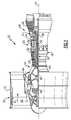
- FIG. 1 schematically illustrates a gas turbine engine 20.
- the gas turbine engine 20 is disclosed herein as a two-spool turbofan that generally incorporates a fan section 22, a compressor section 24, a combustor section 26 and a turbine section 28.
- Alternative engines might include an augmentor section (not shown) among other systems or features.
- the fan section 22 drives air along a bypass flow path B in a bypass duct defined within a nacelle 15, while the compressor section 24 drives air along a core flow path C for compression and communication into the combustor section 26 then expansion through the turbine section 28.
- the exemplary engine 20 generally includes a low speed spool 30 and a high speed spool 32 mounted for rotation about an engine central longitudinal axis A relative to an engine static structure 36 via several bearing systems 38. It should be understood that various bearing systems 38 at various locations may alternatively or additionally be provided, and the location of bearing systems 38 may be varied as appropriate to the application.
- the low speed spool 30 generally includes an inner shaft 40 that interconnects a fan 42, a first (or low) pressure compressor 44 and a first (or low) pressure turbine 46.
- the inner shaft 40 is connected to the fan 42 through a speed change mechanism, which in exemplary gas turbine engine 20 is illustrated as a geared architecture 48 to drive the fan 42 at a lower speed than the low speed spool 30.
- the high speed spool 32 includes an outer shaft 50 that interconnects a second (or high) pressure compressor 52 and a second (or high) pressure turbine 54.
- a combustor 56 is arranged in exemplary gas turbine 20 between the high pressure compressor 52 and the high pressure turbine 54.
- a mid-turbine frame 57 of the engine static structure 36 is arranged generally between the high pressure turbine 54 and the low pressure turbine 46.
- the mid-turbine frame 57 further supports bearing systems 38 in the turbine section 28.
- the inner shaft 40 and the outer shaft 50 are concentric and rotate via bearing systems 38 about the engine central longitudinal axis A which is collinear with their longitudinal axes.
- the core airflow is compressed by the low pressure compressor 44 then the high pressure compressor 52, mixed and burned with fuel in the combustor 56, then expanded over the high pressure turbine 54 and low pressure turbine 46.
- the mid-turbine frame 57 includes airfoils 59 which are in the core airflow path C.
- the turbines 46, 54 rotationally drive the respective low speed spool 30 and high speed spool 32 in response to the expansion.
- gear system 48 may be located aft of combustor section 26 or even aft of turbine section 28, and fan section 22 may be positioned forward or aft of the location of gear system 48.
- the engine 20 in one example is a high-bypass geared aircraft engine.
- the engine 20 bypass ratio is greater than about six (6), with an example embodiment being greater than about ten (10)
- the geared architecture 48 is an epicyclic gear train, such as a planetary gear system or other gear system, with a gear reduction ratio of greater than about 2.3
- the low pressure turbine 46 has a pressure ratio that is greater than about five.
- the engine 20 bypass ratio is greater than about ten (10:1)
- the fan diameter is significantly larger than that of the low pressure compressor 44
- the low pressure turbine 46 has a pressure ratio that is greater than about five 5:1.
- Low pressure turbine 46 pressure ratio is pressure measured prior to inlet of low pressure turbine 46 as related to the pressure at the outlet of the low pressure turbine 46 prior to an exhaust nozzle.
- the geared architecture 48 may be an epicycle gear train, such as a planetary gear system or other gear system, with a gear reduction ratio of greater than about 2.3:1. It should be understood, however, that the above parameters are only exemplary of one embodiment of a geared architecture engine and that the present invention is applicable to other gas turbine engines including direct drive turbofans.
- the fan section 22 of the engine 20 is designed for a particular flight condition -- typically cruise at about 0.8 Mach and about 35,000 feet (10,668 meters).
- the flight condition of 0.8 Mach and 35,000 ft (10,668 meters), with the engine at its best fuel consumption - also known as "bucket cruise Thrust Specific Fuel Consumption ('TSFC')" - is the industry standard parameter of Ibm of fuel being burned divided by lbf of thrust the engine produces at that minimum point.
- "Low fan pressure ratio” is the pressure ratio across the fan blade alone, without a Fan Exit Guide Vane (“FEGV”) system.
- the low fan pressure ratio as disclosed herein according to one non-limiting embodiment is less than about 1.45.
- Low corrected fan tip speed is the actual fan tip speed in ft/sec divided by an industry standard temperature correction of [(Tram °R) / (518.7 °R)] 0.5 .
- the "Low corrected fan tip speed” as disclosed herein according to one non-limiting embodiment is less than about 1150 ft / second (350.5 meters/second).
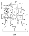
- FIG. 2 illustrates an enlarged schematic view of the high pressure turbine 54, however, other sections of the gas turbine engine 20 could benefit from this disclosure.
- the high pressure turbine 54 includes a two-stage turbine section with a first rotor assembly 60 and a second rotor assembly 62.
- the first rotor assembly 60 includes a first array of rotor blades 64 circumferentially spaced around a first disk 68 and the second rotor assembly 62 includes a second array of rotor blades 66 circumferentially spaced around a second disk 70.
- Each of the first and second array of rotor blades 64, 66 include a respective first root portion 72 and a second root portion 74, a first platform 76 and a second platform 78, and a first airfoil 80 and a second airfoil 82.
- Each of the first and second root portions 72, 74 is received within a respective first rim and a second rim 84, 86 of the first and second disk 68, 70.
- the first airfoil 80 and the second airfoil 82 extend radially outward toward a first and second blade outer air seal (BOAS) assembly 81, 83, respectively.
- BOAS blade outer air seal
- the first and second array of rotor blades 64, 66 are disposed in the core flow path that is pressurized in the compressor section 24 then heated to a working temperature in the combustor section 26.
- the first and second platforms 76, 78 separate a gas path side inclusive of the first and second airfoils 80, 82 and a non-gas path side inclusive of the first and second root portions 72, 74.
- the shroud assembly 88 includes an array of vanes 90 that each include at least two airfoils 91 that extend between a respective inner vane platform 92 and an outer vane platform 94.
- the outer vane platform 94 of the vane 90 may at least partially engage the first and second BOAS 81, 83.
- Figure 3 illustrates an enlarged view of the region surrounding a leading edge 106 of the outer vane platform 94 of the vane 90.
- the outer vane platform 94 of the vane 90 includes a vane hook 102, at least one anti-rotation tabs 104, and the leading edge 106 adjacent the gas path.
- the vane hook 102 engages a recess 108 formed in the engine static structure 36 to limit radial and axially forward movement of the vane 90 relative to the engine static structure 36.
- the anti-rotation tabs 104 includes a primary anti-rotation tab 104a ( Figure 4 ) on the vane 90.
- each vane 90 includes a pair of airfoils 91 extending between the outer vane platform 94 and inner vane platform 92, and a primary anti-rotation tab 104a.
- the primary anti-rotation tab 104a includes a pair of circumferential faces 105 ( Figure 4 ) that engage corresponding circumferential faces 110a on anti-rotation protrusions 110 that extend radially inward from the engine static structure 36 to prevent the vane 90 from rotating circumferentially during operation.
- the circumferential faces 110a on the anti-rotation protrusions 110 extend along the axis A.
- the anti-rotation protrusions 110 engage a forward and radially outer portion of the anti-rotation tab 104. Although the anti-rotation protrusions 110 are shown in pairs, only one anti-rotation protrusion 110 could be used to engage the primary anti-rotation tab 104a.
- the engine static structure 36 only includes one of the pairs of anti-rotation protrusions 110 per vane 90 as shown in Figure 4 .
- the anti-rotation tabs 104 extends from a radially outer portion of the outer vane platform 94 and is located radially inward from the vane hook 102.
- the anti-rotation tabs 104 extend axially forward from the outer vane platform 94 and include a simple cross section, such as a square or rectangle, to simplify the manufacturing process.
- a blade outer air seal support structure 100 and the blade outer air seal 81 also engage at least one of the anti-rotation tabs 104 to prevent circumferential movement of the blade outer air seal support structure 100 and the blade outer air seal 81.
- the blade outer air seal support structure 100 includes a feature 114, such as a pair of tabs (only one shown), that engages corresponding circumferential faces on the primary anti-rotation tab 104a to prevent rotation of the blade out air seal support structure 100.
- the features 114 engage a forward and radially inner portion of the primary anti-rotation tab 104a.
- the BOAS 81 includes a feature 116, such as a pair of tabs (only one shown), that engages corresponding circumferential faces on the primary anti-rotation tab 104a to prevent rotation of the BOAS 81.
- the feature 116 engages a middle and a radially inner portion of the primary anti-rotation tab 104a.
- a shield 118 is located adjacent a radially inner surface of the anti-rotation feature 104 and a downstream surface of the feature 116 on the BOAS 81.
- the shield 118 forms a circumferential hoop that surrounds the axis A of the gas turbine engine 20.
- the shield 118 forms a continuous hoop without any discontinuities and in another example the shield 118 includes a discontinuity forming a split in the hoop.
- the shield 118 forms a continuous surface that to engage a seal 120 located between the vane 90 and the BOAS 81.
- the seal is a "W" shaped seal pointing radially outward. The seal reduces discrete contact points on the shield 118 where the shield 118 contacts the anti-rotation tab 104 and the feature 116.
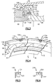
- Figure 5 illustrates a cross sectional view of the shield 118.
- the shield 118 includes a first portion 122 extending radially on an axially upstream end of the shield 118 and a second portion 124 extending axially from a radially outer end of the first portion 122.
- the shield 118 forms a complete unitary circumferential hoop that surrounds the axis A of the gas turbine engine 20.
- the shield 118 forms a circumferential hoop with a single discontinuity.
- the shield 118 forms a circumferential hoop with at least two discontinuities.
- the second portion 122 of the shield 118 is located radially outward from the seal 120 and the first portion 122 of the shield 118 is located axially upstream from the seal 120.
- Figure 6 illustrates a cross-sectional view of another example shield 218.
- the shield 218 is similar to the shield 118 except where described below or shown in the drawings.
- the shield 218 includes a first portion 222 extending radially on an axially downstream end of the shield 218 and a second portion 224 extending axially from a radially outer end of the first portion 222.
- the shield 218 forms a complete unitary circumferential hoop that surrounds the axis A of the gas turbine engine 20.
- the shield 218 forms a circumferential hoop with a single discontinuity.
- the shield 218 forms a circumferential hoop with at least two discontinuities.
- the second portion 222 of the shield 218 is located radially outward from the seal 220 and the first portion 222 of the shield 218 is located axially downstream from the seal 120.
Abstract
Description
- A gas turbine engine typically includes a fan section, a compressor section, a combustor section, and a turbine section. Air entering the compressor section is compressed and delivered into the combustion section where it is mixed with fuel and ignited to generate a high-speed exhaust gas flow. The high-speed exhaust gas flow expands through the turbine section to drive the compressor and the fan section.
- Various components are attached to a static structure on the gas turbine engine, such as vanes, that must be prevented from rotating in a circumferential direction relative to the static structure. In order to prevent the circumferential rotation of the components, some form of engagement between the component and the static structure must be formed.
- In one exemplary embodiment, a gas turbine engine assembly includes a shield that has a first portion and a second portion. The first portion extends radially from an axial end portion of the shield and includes a blade outer air seal contact surface. The second portion extends axially from a radially outer end of the first portion and includes a vane contact surface.
- In a further embodiment of the above, the shield forms a complete unitary circumferential hoop.
- In a further embodiment of any of the above, the shield forms a circumferential hoop with a single discontinuity.
- In a further embodiment of any of the above, a seal is in contact with the shield.
- In a further embodiment of any of the above, the second portion of the shield is located radially outward from the seal. The first portion of the shield is located axially upstream from the seal.
- In a further embodiment of any of the above, the seal includes a "W" shaped cross section pointing radially outward.
- In a further embodiment of any of the above, the second portion of the shield is located radially outward from the seal and the first portion of the shield is located axially downstream from the seal.
- In another exemplary embodiment, a gas turbine engine includes at least one vane. At least one blade outer air seal is adjacent at least one vane. A shield is located axially between the at least one vane and the at least one blade outer air seal. A seal is located radially inward from the shield.
- In a further embodiment of any of the above, the shield comprises a first portion that extends radially on an axially upstream end of the shield.
- In a further embodiment of any of the above, the shield comprises a first portion that extends radially on an axially downstream end of the shield.
- In a further embodiment of any of the above, the shield comprises a second portion that extends axially from a radially outer end of the first portion.
- In a further embodiment of any of the above, the second portion of the shield is located radially outward from the seal. The first portion of the shield is located axially upstream from the seal.
- In a further embodiment of any of the above, at least one vane includes at least one anti-rotation tab
- In a further embodiment of any of the above, at least one blade outer air seal includes a feature for engaging at least one anti-rotation tab.
- In a further embodiment of any of the above, an engine static structure has a plurality anti-rotation protrusions and at least one anti-rotation tab engages one of the plurality anti-rotation protrusions.
- In a further embodiment of any of the above, at least one blade outer air seal includes a feature for engaging the at least one of anti-rotation tab.
- In a further embodiment of any of the above, the seal directly contacts the shield and includes a "W" shaped cross section.
- In another exemplary embodiment, a method assembling a portion of a gas turbine engine includes positioning a shield in abutting contact with a blade outer air seal. A seal is positioned in abutting contact with the shield and the blade outer air seal. A vane is positioned in abutting contact with the shield.
- In a further embodiment of any of the above, the shield is located axially between the vane and the blade outer air seal and the seal is located radially inward from the shield.
- In a further embodiment of any of the above, the shield comprises a first portion that extends radially on an axially upstream end of the shield. A second portion extends axially from a radially outer end of the first portion.
-
-
Figure 1 is a schematic view of an example gas turbine engine. -
Figure 2 illustrates a schematic view of an example turbine section of the gas turbine engine. -
Figure 3 illustrates an enlarged view of the turbine section. -
Figure 4 illustrates a perspective view of a pair of vane doublets. -
Figure 5 illustrates a cross-sectional view of an example shield. -
Figure 6 illustrates a cross-sectional view of another example shield. -
Figure 1 schematically illustrates agas turbine engine 20. Thegas turbine engine 20 is disclosed herein as a two-spool turbofan that generally incorporates afan section 22, acompressor section 24, acombustor section 26 and aturbine section 28. Alternative engines might include an augmentor section (not shown) among other systems or features. Thefan section 22 drives air along a bypass flow path B in a bypass duct defined within anacelle 15, while thecompressor section 24 drives air along a core flow path C for compression and communication into thecombustor section 26 then expansion through theturbine section 28. Although depicted as a two-spool turbofan gas turbine engine in the disclosed non-limiting embodiment, it should be understood that the concepts described herein are not limited to use with two-spool turbofans as the teachings may be applied to other types of turbine engines including three-spool architectures. - The
exemplary engine 20 generally includes alow speed spool 30 and ahigh speed spool 32 mounted for rotation about an engine central longitudinal axis A relative to an enginestatic structure 36 viaseveral bearing systems 38. It should be understood thatvarious bearing systems 38 at various locations may alternatively or additionally be provided, and the location ofbearing systems 38 may be varied as appropriate to the application. - The
low speed spool 30 generally includes aninner shaft 40 that interconnects afan 42, a first (or low)pressure compressor 44 and a first (or low)pressure turbine 46. Theinner shaft 40 is connected to thefan 42 through a speed change mechanism, which in exemplarygas turbine engine 20 is illustrated as a gearedarchitecture 48 to drive thefan 42 at a lower speed than thelow speed spool 30. Thehigh speed spool 32 includes anouter shaft 50 that interconnects a second (or high)pressure compressor 52 and a second (or high)pressure turbine 54. Acombustor 56 is arranged inexemplary gas turbine 20 between thehigh pressure compressor 52 and thehigh pressure turbine 54. Amid-turbine frame 57 of the enginestatic structure 36 is arranged generally between thehigh pressure turbine 54 and thelow pressure turbine 46. Themid-turbine frame 57 further supports bearingsystems 38 in theturbine section 28. Theinner shaft 40 and theouter shaft 50 are concentric and rotate viabearing systems 38 about the engine central longitudinal axis A which is collinear with their longitudinal axes. - The core airflow is compressed by the
low pressure compressor 44 then thehigh pressure compressor 52, mixed and burned with fuel in thecombustor 56, then expanded over thehigh pressure turbine 54 andlow pressure turbine 46. Themid-turbine frame 57 includesairfoils 59 which are in the core airflow path C. Theturbines low speed spool 30 andhigh speed spool 32 in response to the expansion. It will be appreciated that each of the positions of thefan section 22,compressor section 24,combustor section 26,turbine section 28, and fandrive gear system 48 may be varied. For example,gear system 48 may be located aft ofcombustor section 26 or even aft ofturbine section 28, andfan section 22 may be positioned forward or aft of the location ofgear system 48. - The
engine 20 in one example is a high-bypass geared aircraft engine. In a further example, theengine 20 bypass ratio is greater than about six (6), with an example embodiment being greater than about ten (10), the gearedarchitecture 48 is an epicyclic gear train, such as a planetary gear system or other gear system, with a gear reduction ratio of greater than about 2.3 and thelow pressure turbine 46 has a pressure ratio that is greater than about five. In one disclosed embodiment, theengine 20 bypass ratio is greater than about ten (10:1), the fan diameter is significantly larger than that of thelow pressure compressor 44, and thelow pressure turbine 46 has a pressure ratio that is greater than about five 5:1.Low pressure turbine 46 pressure ratio is pressure measured prior to inlet oflow pressure turbine 46 as related to the pressure at the outlet of thelow pressure turbine 46 prior to an exhaust nozzle. The gearedarchitecture 48 may be an epicycle gear train, such as a planetary gear system or other gear system, with a gear reduction ratio of greater than about 2.3:1. It should be understood, however, that the above parameters are only exemplary of one embodiment of a geared architecture engine and that the present invention is applicable to other gas turbine engines including direct drive turbofans. - A significant amount of thrust is provided by the bypass flow B due to the high bypass ratio. The
fan section 22 of theengine 20 is designed for a particular flight condition -- typically cruise at about 0.8 Mach and about 35,000 feet (10,668 meters). The flight condition of 0.8 Mach and 35,000 ft (10,668 meters), with the engine at its best fuel consumption - also known as "bucket cruise Thrust Specific Fuel Consumption ('TSFC')" - is the industry standard parameter of Ibm of fuel being burned divided by lbf of thrust the engine produces at that minimum point. "Low fan pressure ratio" is the pressure ratio across the fan blade alone, without a Fan Exit Guide Vane ("FEGV") system. The low fan pressure ratio as disclosed herein according to one non-limiting embodiment is less than about 1.45. "Low corrected fan tip speed" is the actual fan tip speed in ft/sec divided by an industry standard temperature correction of [(Tram °R) / (518.7 °R)]0.5. The "Low corrected fan tip speed" as disclosed herein according to one non-limiting embodiment is less than about 1150 ft / second (350.5 meters/second). -
Figure 2 illustrates an enlarged schematic view of thehigh pressure turbine 54, however, other sections of thegas turbine engine 20 could benefit from this disclosure. Thehigh pressure turbine 54 includes a two-stage turbine section with afirst rotor assembly 60 and asecond rotor assembly 62. - The
first rotor assembly 60 includes a first array ofrotor blades 64 circumferentially spaced around afirst disk 68 and thesecond rotor assembly 62 includes a second array ofrotor blades 66 circumferentially spaced around asecond disk 70. Each of the first and second array ofrotor blades first root portion 72 and asecond root portion 74, afirst platform 76 and asecond platform 78, and afirst airfoil 80 and asecond airfoil 82. Each of the first andsecond root portions second rim second disk first airfoil 80 and thesecond airfoil 82 extend radially outward toward a first and second blade outer air seal (BOAS)assembly - The first and second array of
rotor blades compressor section 24 then heated to a working temperature in thecombustor section 26. The first andsecond platforms second airfoils second root portions - A
shroud assembly 88 within theengine case structure 36 between thefirst rotor assembly 60 and thesecond rotor assembly 62 directs the hot gas core airflow in the core flow path from the first array ofrotor blades 64 to the second array ofrotor blades 66. Theshroud assembly 88 includes an array ofvanes 90 that each include at least twoairfoils 91 that extend between a respectiveinner vane platform 92 and anouter vane platform 94. Theouter vane platform 94 of thevane 90 may at least partially engage the first andsecond BOAS -
Figure 3 illustrates an enlarged view of the region surrounding aleading edge 106 of theouter vane platform 94 of thevane 90. In the illustrated example, theouter vane platform 94 of thevane 90 includes avane hook 102, at least oneanti-rotation tabs 104, and theleading edge 106 adjacent the gas path. Thevane hook 102 engages arecess 108 formed in the enginestatic structure 36 to limit radial and axially forward movement of thevane 90 relative to the enginestatic structure 36. - The
anti-rotation tabs 104 includes aprimary anti-rotation tab 104a (Figure 4 ) on thevane 90. In the illustrated example, eachvane 90 includes a pair ofairfoils 91 extending between theouter vane platform 94 andinner vane platform 92, and aprimary anti-rotation tab 104a. Theprimary anti-rotation tab 104a includes a pair of circumferential faces 105 (Figure 4 ) that engage corresponding circumferential faces 110a onanti-rotation protrusions 110 that extend radially inward from the enginestatic structure 36 to prevent thevane 90 from rotating circumferentially during operation. The circumferential faces 110a on theanti-rotation protrusions 110 extend along the axis A. As shown inFigure 3 , theanti-rotation protrusions 110 engage a forward and radially outer portion of theanti-rotation tab 104. Although theanti-rotation protrusions 110 are shown in pairs, only oneanti-rotation protrusion 110 could be used to engage theprimary anti-rotation tab 104a. - The engine
static structure 36 only includes one of the pairs ofanti-rotation protrusions 110 pervane 90 as shown inFigure 4 . Theanti-rotation tabs 104 extends from a radially outer portion of theouter vane platform 94 and is located radially inward from thevane hook 102. Theanti-rotation tabs 104 extend axially forward from theouter vane platform 94 and include a simple cross section, such as a square or rectangle, to simplify the manufacturing process. - A blade outer air
seal support structure 100 and the bladeouter air seal 81 also engage at least one of theanti-rotation tabs 104 to prevent circumferential movement of the blade outer airseal support structure 100 and the bladeouter air seal 81. As shown inFigure 3 , the blade outer airseal support structure 100 includes afeature 114, such as a pair of tabs (only one shown), that engages corresponding circumferential faces on theprimary anti-rotation tab 104a to prevent rotation of the blade out airseal support structure 100. In the illustrated example, thefeatures 114 engage a forward and radially inner portion of theprimary anti-rotation tab 104a. - As shown in
Figure 3 , theBOAS 81 includes afeature 116, such as a pair of tabs (only one shown), that engages corresponding circumferential faces on theprimary anti-rotation tab 104a to prevent rotation of theBOAS 81. In the illustrated example, thefeature 116 engages a middle and a radially inner portion of theprimary anti-rotation tab 104a. - A
shield 118 is located adjacent a radially inner surface of theanti-rotation feature 104 and a downstream surface of thefeature 116 on theBOAS 81. Theshield 118 forms a circumferential hoop that surrounds the axis A of thegas turbine engine 20. In one example, theshield 118 forms a continuous hoop without any discontinuities and in another example theshield 118 includes a discontinuity forming a split in the hoop. - The
shield 118 forms a continuous surface that to engage aseal 120 located between thevane 90 and theBOAS 81. In the illustrated example, the seal is a "W" shaped seal pointing radially outward. The seal reduces discrete contact points on theshield 118 where theshield 118 contacts theanti-rotation tab 104 and thefeature 116. -
Figure 5 illustrates a cross sectional view of theshield 118. Theshield 118 includes afirst portion 122 extending radially on an axially upstream end of theshield 118 and asecond portion 124 extending axially from a radially outer end of thefirst portion 122. In one example, theshield 118 forms a complete unitary circumferential hoop that surrounds the axis A of thegas turbine engine 20. In another example, theshield 118 forms a circumferential hoop with a single discontinuity. In yet another example, theshield 118 forms a circumferential hoop with at least two discontinuities. - In the illustrated example, the
second portion 122 of theshield 118 is located radially outward from theseal 120 and thefirst portion 122 of theshield 118 is located axially upstream from theseal 120. -
Figure 6 illustrates a cross-sectional view of anotherexample shield 218. Theshield 218 is similar to theshield 118 except where described below or shown in the drawings. Theshield 218 includes afirst portion 222 extending radially on an axially downstream end of theshield 218 and asecond portion 224 extending axially from a radially outer end of thefirst portion 222. In one example, theshield 218 forms a complete unitary circumferential hoop that surrounds the axis A of thegas turbine engine 20. In another example, theshield 218 forms a circumferential hoop with a single discontinuity. In yet another example, theshield 218 forms a circumferential hoop with at least two discontinuities. - In the illustrated example, the
second portion 222 of theshield 218 is located radially outward from the seal 220 and thefirst portion 222 of theshield 218 is located axially downstream from theseal 120. - The preceding description is exemplary rather than limiting in nature. Variations and modifications to the disclosed examples may become apparent to those skilled in the art that do not necessarily depart from the essence of this disclosure. The scope of legal protection given to this disclosure can only be determined by studying the following claims.
Claims (15)
- A gas turbine engine assembly (20) comprising:a shield (118) having a first portion (122) and a second portion (124), the first portion (122) extending radially from an axial end portion of the shield (118) including a blade outer air seal contact surface and the second portion (124) extending axially from a radially outer end of the first portion (122) including a vane contact surface.
- The gas turbine engine assembly of claim 1, wherein the shield (118) forms a complete unitary circumferential hoop.
- The gas turbine engine assembly of claim 1, wherein the shield (118) forms a circumferential hoop with a single discontinuity.
- The gas turbine engine assembly of any preceding claim, comprising a seal (120) in contact with the shield.
- The gas turbine engine assembly of claim 4, wherein the second portion of the shield (118) is located radially outward from the seal (120) and the first portion of the shield is located axially upstream from the seal (120), or axially downstream from the seal (120).
- The gas turbine engine assembly of claim 4 or 5, wherein the seal (120) includes a "W" shaped cross section pointing radially outward.
- A gas turbine engine (20) comprising:at least one vane (90);at least one blade outer air seal (81) adjacent the at least one vane (90);a shield (118) located axially between the at least one vane (90) and the at least one blade outer air seal (81); anda seal (120) located radially inward from the shield (118).
- The gas turbine engine of claim 7, wherein the shield (118) comprises a first portion (122) extending radially on an axially upstream end of the shield (118).
- The gas turbine engine of claim 7 wherein the shield (118) comprises a first portion (122) extending radially on an axially downstream end of the shield (118).
- The gas turbine engine of claim 8, wherein the shield comprises a second portion (124) extending axially from a radially outer end of the first portion (122), wherein the second portion (124) of the shield (118) is optionally located radially outward from the seal (120) and the first portion (122) of the shield is optionally located axially upstream from the seal (120).
- The gas turbine engine of any of claims 7 to 10, wherein the at least one vane (90) includes at least one anti-rotation tab (104).
- The gas turbine engine of claim 11, wherein:the at least one blade outer air seal (81) includes a feature (116) for engaging the at least one anti-rotation tab (104); and/orthe gas turbine engine comprises an engine static structure with a plurality anti-rotation protrusions (110) and the at least one anti-rotation tab (104) engages one of the plurality anti-rotation protrusions (110); and/orthe at least one blade outer air seal includes a feature for engaging the at least one of anti-rotation tab (104).
- The gas turbine engine of any of claims 7 to 12, wherein the seal (120) directly contacts the shield (118) and includes a "W" shaped cross section.
- A method assembling a portion of a gas turbine engine (20) comprising:positioning a shield (118) in abutting contact with a blade outer air seal (81);positioning a seal (120) in abutting contact with the shield (118) and the blade outer air seal (81); andpositioning a vane (90) in abutting contact with the shield (118).
- The method of claim 14, wherein the shield (118) is located axially between the vane (90) and the blade outer air seal (81) and the seal (120) is located radially inward from the shield (118), wherein the shield (118) optionally comprises a first portion (122) extending radially on an axially upstream end of the shield (118) and a second portion (124) extending axially from a radially outer end of the first portion (122).
Applications Claiming Priority (1)
| Application Number | Priority Date | Filing Date | Title |
|---|---|---|---|
| US14/790,076 US10385716B2 (en) | 2015-07-02 | 2015-07-02 | Seal for a gas turbine engine |
Publications (2)
| Publication Number | Publication Date |
|---|---|
| EP3112606A1 true EP3112606A1 (en) | 2017-01-04 |
| EP3112606B1 EP3112606B1 (en) | 2019-04-10 |
Family
ID=56345055
Family Applications (1)
| Application Number | Title | Priority Date | Filing Date |
|---|---|---|---|
| EP16177836.0A Active EP3112606B1 (en) | 2015-07-02 | 2016-07-04 | A seal for a gas turbine engine |
Country Status (2)
| Country | Link |
|---|---|
| US (1) | US10385716B2 (en) |
| EP (1) | EP3112606B1 (en) |
Cited By (3)
| Publication number | Priority date | Publication date | Assignee | Title |
|---|---|---|---|---|
| EP3653843A1 (en) * | 2018-11-19 | 2020-05-20 | United Technologies Corporation | Air seal interface with forward engagement features and active clearance control for a gas turbine engine |
| EP3653842A1 (en) * | 2018-11-19 | 2020-05-20 | United Technologies Corporation | Air seal interface with aft engagement features and active clearance control for a gas turbine engine |
| US10822964B2 (en) | 2018-11-13 | 2020-11-03 | Raytheon Technologies Corporation | Blade outer air seal with non-linear response |
Families Citing this family (5)
| Publication number | Priority date | Publication date | Assignee | Title |
|---|---|---|---|---|
| JP5717904B1 (en) * | 2014-08-04 | 2015-05-13 | 三菱日立パワーシステムズ株式会社 | Stator blade, gas turbine, split ring, stator blade remodeling method, and split ring remodeling method |
| US10378371B2 (en) * | 2014-12-18 | 2019-08-13 | United Technologies Corporation | Anti-rotation vane |
| US10533446B2 (en) | 2017-05-15 | 2020-01-14 | United Technologies Corporation | Alternative W-seal groove arrangement |
| KR101937586B1 (en) * | 2017-09-12 | 2019-01-10 | 두산중공업 주식회사 | Vane of turbine, turbine and gas turbine comprising it |
| FR3096395B1 (en) * | 2019-05-21 | 2021-04-23 | Safran Aircraft Engines | Turbine for a turbomachine, such as a turbojet or an aircraft turboprop |
Citations (3)
| Publication number | Priority date | Publication date | Assignee | Title |
|---|---|---|---|---|
| US20120128465A1 (en) * | 2010-11-19 | 2012-05-24 | General Electric Company | Self-aligning flow splitter for steam turbine |
| US20120207603A1 (en) * | 2009-06-16 | 2012-08-16 | General Electric Company | Trapped spring balance weight and rotor assembly |
| WO2015089431A1 (en) * | 2013-12-12 | 2015-06-18 | United Technologies Corporation | Blade outer air seal with secondary air sealing |
Family Cites Families (14)
| Publication number | Priority date | Publication date | Assignee | Title |
|---|---|---|---|---|
| US4687413A (en) * | 1985-07-31 | 1987-08-18 | United Technologies Corporation | Gas turbine engine assembly |
| US4820116A (en) | 1987-09-18 | 1989-04-11 | United Technologies Corporation | Turbine cooling for gas turbine engine |
| US5158430A (en) | 1990-09-12 | 1992-10-27 | United Technologies Corporation | Segmented stator vane seal |
| US5224822A (en) * | 1991-05-13 | 1993-07-06 | General Electric Company | Integral turbine nozzle support and discourager seal |
| US5429478A (en) | 1994-03-31 | 1995-07-04 | United Technologies Corporation | Airfoil having a seal and an integral heat shield |
| US6076835A (en) | 1997-05-21 | 2000-06-20 | Allison Advanced Development Company | Interstage van seal apparatus |
| US6273683B1 (en) | 1999-02-05 | 2001-08-14 | Siemens Westinghouse Power Corporation | Turbine blade platform seal |
| RU2302534C2 (en) * | 2001-12-11 | 2007-07-10 | Альстом (Свитзерлэнд) Лтд. | Gas-turbine device |
| US7500824B2 (en) | 2006-08-22 | 2009-03-10 | General Electric Company | Angel wing abradable seal and sealing method |
| US7946801B2 (en) * | 2007-12-27 | 2011-05-24 | General Electric Company | Multi-source gas turbine cooling |
| DE102008011746A1 (en) | 2008-02-28 | 2009-09-03 | Mtu Aero Engines Gmbh | Device and method for diverting a leakage current |
| US8534995B2 (en) | 2009-03-05 | 2013-09-17 | United Technologies Corporation | Turbine engine sealing arrangement |
| US8696320B2 (en) | 2009-03-12 | 2014-04-15 | General Electric Company | Gas turbine having seal assembly with coverplate and seal |
| US8998573B2 (en) * | 2010-10-29 | 2015-04-07 | General Electric Company | Resilient mounting apparatus for low-ductility turbine shroud |
-
2015
- 2015-07-02 US US14/790,076 patent/US10385716B2/en active Active
-
2016
- 2016-07-04 EP EP16177836.0A patent/EP3112606B1/en active Active
Patent Citations (3)
| Publication number | Priority date | Publication date | Assignee | Title |
|---|---|---|---|---|
| US20120207603A1 (en) * | 2009-06-16 | 2012-08-16 | General Electric Company | Trapped spring balance weight and rotor assembly |
| US20120128465A1 (en) * | 2010-11-19 | 2012-05-24 | General Electric Company | Self-aligning flow splitter for steam turbine |
| WO2015089431A1 (en) * | 2013-12-12 | 2015-06-18 | United Technologies Corporation | Blade outer air seal with secondary air sealing |
Cited By (6)
| Publication number | Priority date | Publication date | Assignee | Title |
|---|---|---|---|---|
| US10822964B2 (en) | 2018-11-13 | 2020-11-03 | Raytheon Technologies Corporation | Blade outer air seal with non-linear response |
| EP3653843A1 (en) * | 2018-11-19 | 2020-05-20 | United Technologies Corporation | Air seal interface with forward engagement features and active clearance control for a gas turbine engine |
| EP3653842A1 (en) * | 2018-11-19 | 2020-05-20 | United Technologies Corporation | Air seal interface with aft engagement features and active clearance control for a gas turbine engine |
| US10920618B2 (en) | 2018-11-19 | 2021-02-16 | Raytheon Technologies Corporation | Air seal interface with forward engagement features and active clearance control for a gas turbine engine |
| US10934941B2 (en) | 2018-11-19 | 2021-03-02 | Raytheon Technologies Corporation | Air seal interface with AFT engagement features and active clearance control for a gas turbine engine |
| US11339722B2 (en) | 2018-11-19 | 2022-05-24 | Raytheon Technologies Corporation | Air seal interface with AFT engagement features and active clearance control for a gas turbine engine |
Also Published As
| Publication number | Publication date |
|---|---|
| US10385716B2 (en) | 2019-08-20 |
| US20170002675A1 (en) | 2017-01-05 |
| EP3112606B1 (en) | 2019-04-10 |
Similar Documents
| Publication | Publication Date | Title |
|---|---|---|
| EP3112606B1 (en) | A seal for a gas turbine engine | |
| EP3064711B1 (en) | Component for a gas turbine engine, corresponding gas turbine engine and method of forming an airfoil | |
| US11421558B2 (en) | Gas turbine engine component | |
| US10753220B2 (en) | Gas turbine engine component | |
| US9863259B2 (en) | Chordal seal | |
| EP3628818A1 (en) | Impingement cooling for gas turbine engine component | |
| US10746033B2 (en) | Gas turbine engine component | |
| US10329931B2 (en) | Stator assembly for a gas turbine engine | |
| EP3043030B1 (en) | Anti-rotation vane | |
| US9869195B2 (en) | Support assembly for a gas turbine engine | |
| US10968777B2 (en) | Chordal seal | |
| EP3095971B1 (en) | Support assembly for a gas turbine engine | |
| EP3095967B1 (en) | Support assembly for a gas turbine engine | |
| EP3091199A1 (en) | Airfoil and corresponding vane | |
| EP3550105B1 (en) | Gas turbine engine rotor disk | |
| US20200056495A1 (en) | Gas turbine engine having cantilevered stators | |
| EP3290717A1 (en) | Compressor blade with specific spanwise pressure and velocity profile |
Legal Events
| Date | Code | Title | Description |
|---|---|---|---|
| PUAI | Public reference made under article 153(3) epc to a published international application that has entered the european phase |
Free format text: ORIGINAL CODE: 0009012 |
|
| STAA | Information on the status of an ep patent application or granted ep patent |
Free format text: STATUS: THE APPLICATION HAS BEEN PUBLISHED |
|
| AK | Designated contracting states |
Kind code of ref document: A1 Designated state(s): AL AT BE BG CH CY CZ DE DK EE ES FI FR GB GR HR HU IE IS IT LI LT LU LV MC MK MT NL NO PL PT RO RS SE SI SK SM TR |
|
| AX | Request for extension of the european patent |
Extension state: BA ME |
|
| STAA | Information on the status of an ep patent application or granted ep patent |
Free format text: STATUS: REQUEST FOR EXAMINATION WAS MADE |
|
| 17P | Request for examination filed |
Effective date: 20170620 |
|
| RBV | Designated contracting states (corrected) |
Designated state(s): AL AT BE BG CH CY CZ DE DK EE ES FI FR GB GR HR HU IE IS IT LI LT LU LV MC MK MT NL NO PL PT RO RS SE SI SK SM TR |
|
| RIC1 | Information provided on ipc code assigned before grant |
Ipc: F01D 9/04 20060101ALI20180622BHEP Ipc: F01D 9/02 20060101ALI20180622BHEP Ipc: F01D 11/00 20060101ALI20180622BHEP Ipc: F01D 11/12 20060101AFI20180622BHEP Ipc: F02C 7/28 20060101ALI20180622BHEP |
|
| GRAP | Despatch of communication of intention to grant a patent |
Free format text: ORIGINAL CODE: EPIDOSNIGR1 |
|
| STAA | Information on the status of an ep patent application or granted ep patent |
Free format text: STATUS: GRANT OF PATENT IS INTENDED |
|
| INTG | Intention to grant announced |
Effective date: 20181015 |
|
| GRAS | Grant fee paid |
Free format text: ORIGINAL CODE: EPIDOSNIGR3 |
|
| GRAA | (expected) grant |
Free format text: ORIGINAL CODE: 0009210 |
|
| STAA | Information on the status of an ep patent application or granted ep patent |
Free format text: STATUS: THE PATENT HAS BEEN GRANTED |
|
| AK | Designated contracting states |
Kind code of ref document: B1 Designated state(s): AL AT BE BG CH CY CZ DE DK EE ES FI FR GB GR HR HU IE IS IT LI LT LU LV MC MK MT NL NO PL PT RO RS SE SI SK SM TR |
|
| REG | Reference to a national code |
Ref country code: GB Ref legal event code: FG4D |
|
| REG | Reference to a national code |
Ref country code: CH Ref legal event code: EP Ref country code: AT Ref legal event code: REF Ref document number: 1118919 Country of ref document: AT Kind code of ref document: T Effective date: 20190415 |
|
| REG | Reference to a national code |
Ref country code: IE Ref legal event code: FG4D |
|
| REG | Reference to a national code |
Ref country code: DE Ref legal event code: R096 Ref document number: 602016012122 Country of ref document: DE |
|
| REG | Reference to a national code |
Ref country code: NL Ref legal event code: MP Effective date: 20190410 |
|
| REG | Reference to a national code |
Ref country code: LT Ref legal event code: MG4D |
|
| REG | Reference to a national code |
Ref country code: AT Ref legal event code: MK05 Ref document number: 1118919 Country of ref document: AT Kind code of ref document: T Effective date: 20190410 |
|
| PG25 | Lapsed in a contracting state [announced via postgrant information from national office to epo] |
Ref country code: NL Free format text: LAPSE BECAUSE OF FAILURE TO SUBMIT A TRANSLATION OF THE DESCRIPTION OR TO PAY THE FEE WITHIN THE PRESCRIBED TIME-LIMIT Effective date: 20190410 |
|
| PG25 | Lapsed in a contracting state [announced via postgrant information from national office to epo] |
Ref country code: HR Free format text: LAPSE BECAUSE OF FAILURE TO SUBMIT A TRANSLATION OF THE DESCRIPTION OR TO PAY THE FEE WITHIN THE PRESCRIBED TIME-LIMIT Effective date: 20190410 Ref country code: LT Free format text: LAPSE BECAUSE OF FAILURE TO SUBMIT A TRANSLATION OF THE DESCRIPTION OR TO PAY THE FEE WITHIN THE PRESCRIBED TIME-LIMIT Effective date: 20190410 Ref country code: PT Free format text: LAPSE BECAUSE OF FAILURE TO SUBMIT A TRANSLATION OF THE DESCRIPTION OR TO PAY THE FEE WITHIN THE PRESCRIBED TIME-LIMIT Effective date: 20190910 Ref country code: SE Free format text: LAPSE BECAUSE OF FAILURE TO SUBMIT A TRANSLATION OF THE DESCRIPTION OR TO PAY THE FEE WITHIN THE PRESCRIBED TIME-LIMIT Effective date: 20190410 Ref country code: ES Free format text: LAPSE BECAUSE OF FAILURE TO SUBMIT A TRANSLATION OF THE DESCRIPTION OR TO PAY THE FEE WITHIN THE PRESCRIBED TIME-LIMIT Effective date: 20190410 Ref country code: NO Free format text: LAPSE BECAUSE OF FAILURE TO SUBMIT A TRANSLATION OF THE DESCRIPTION OR TO PAY THE FEE WITHIN THE PRESCRIBED TIME-LIMIT Effective date: 20190710 Ref country code: AL Free format text: LAPSE BECAUSE OF FAILURE TO SUBMIT A TRANSLATION OF THE DESCRIPTION OR TO PAY THE FEE WITHIN THE PRESCRIBED TIME-LIMIT Effective date: 20190410 Ref country code: FI Free format text: LAPSE BECAUSE OF FAILURE TO SUBMIT A TRANSLATION OF THE DESCRIPTION OR TO PAY THE FEE WITHIN THE PRESCRIBED TIME-LIMIT Effective date: 20190410 |
|
| PG25 | Lapsed in a contracting state [announced via postgrant information from national office to epo] |
Ref country code: BG Free format text: LAPSE BECAUSE OF FAILURE TO SUBMIT A TRANSLATION OF THE DESCRIPTION OR TO PAY THE FEE WITHIN THE PRESCRIBED TIME-LIMIT Effective date: 20190710 Ref country code: GR Free format text: LAPSE BECAUSE OF FAILURE TO SUBMIT A TRANSLATION OF THE DESCRIPTION OR TO PAY THE FEE WITHIN THE PRESCRIBED TIME-LIMIT Effective date: 20190711 Ref country code: RS Free format text: LAPSE BECAUSE OF FAILURE TO SUBMIT A TRANSLATION OF THE DESCRIPTION OR TO PAY THE FEE WITHIN THE PRESCRIBED TIME-LIMIT Effective date: 20190410 Ref country code: LV Free format text: LAPSE BECAUSE OF FAILURE TO SUBMIT A TRANSLATION OF THE DESCRIPTION OR TO PAY THE FEE WITHIN THE PRESCRIBED TIME-LIMIT Effective date: 20190410 Ref country code: PL Free format text: LAPSE BECAUSE OF FAILURE TO SUBMIT A TRANSLATION OF THE DESCRIPTION OR TO PAY THE FEE WITHIN THE PRESCRIBED TIME-LIMIT Effective date: 20190410 |
|
| PG25 | Lapsed in a contracting state [announced via postgrant information from national office to epo] |
Ref country code: IS Free format text: LAPSE BECAUSE OF FAILURE TO SUBMIT A TRANSLATION OF THE DESCRIPTION OR TO PAY THE FEE WITHIN THE PRESCRIBED TIME-LIMIT Effective date: 20190810 Ref country code: AT Free format text: LAPSE BECAUSE OF FAILURE TO SUBMIT A TRANSLATION OF THE DESCRIPTION OR TO PAY THE FEE WITHIN THE PRESCRIBED TIME-LIMIT Effective date: 20190410 |
|
| REG | Reference to a national code |
Ref country code: DE Ref legal event code: R097 Ref document number: 602016012122 Country of ref document: DE |
|
| PG25 | Lapsed in a contracting state [announced via postgrant information from national office to epo] |
Ref country code: EE Free format text: LAPSE BECAUSE OF FAILURE TO SUBMIT A TRANSLATION OF THE DESCRIPTION OR TO PAY THE FEE WITHIN THE PRESCRIBED TIME-LIMIT Effective date: 20190410 Ref country code: DK Free format text: LAPSE BECAUSE OF FAILURE TO SUBMIT A TRANSLATION OF THE DESCRIPTION OR TO PAY THE FEE WITHIN THE PRESCRIBED TIME-LIMIT Effective date: 20190410 Ref country code: SK Free format text: LAPSE BECAUSE OF FAILURE TO SUBMIT A TRANSLATION OF THE DESCRIPTION OR TO PAY THE FEE WITHIN THE PRESCRIBED TIME-LIMIT Effective date: 20190410 Ref country code: CZ Free format text: LAPSE BECAUSE OF FAILURE TO SUBMIT A TRANSLATION OF THE DESCRIPTION OR TO PAY THE FEE WITHIN THE PRESCRIBED TIME-LIMIT Effective date: 20190410 Ref country code: RO Free format text: LAPSE BECAUSE OF FAILURE TO SUBMIT A TRANSLATION OF THE DESCRIPTION OR TO PAY THE FEE WITHIN THE PRESCRIBED TIME-LIMIT Effective date: 20190410 |
|
| PLBE | No opposition filed within time limit |
Free format text: ORIGINAL CODE: 0009261 |
|
| STAA | Information on the status of an ep patent application or granted ep patent |
Free format text: STATUS: NO OPPOSITION FILED WITHIN TIME LIMIT |
|
| PG25 | Lapsed in a contracting state [announced via postgrant information from national office to epo] |
Ref country code: MC Free format text: LAPSE BECAUSE OF FAILURE TO SUBMIT A TRANSLATION OF THE DESCRIPTION OR TO PAY THE FEE WITHIN THE PRESCRIBED TIME-LIMIT Effective date: 20190410 Ref country code: SM Free format text: LAPSE BECAUSE OF FAILURE TO SUBMIT A TRANSLATION OF THE DESCRIPTION OR TO PAY THE FEE WITHIN THE PRESCRIBED TIME-LIMIT Effective date: 20190410 Ref country code: IT Free format text: LAPSE BECAUSE OF FAILURE TO SUBMIT A TRANSLATION OF THE DESCRIPTION OR TO PAY THE FEE WITHIN THE PRESCRIBED TIME-LIMIT Effective date: 20190410 |
|
| REG | Reference to a national code |
Ref country code: CH Ref legal event code: PL |
|
| 26N | No opposition filed |
Effective date: 20200113 |
|
| PG25 | Lapsed in a contracting state [announced via postgrant information from national office to epo] |
Ref country code: TR Free format text: LAPSE BECAUSE OF FAILURE TO SUBMIT A TRANSLATION OF THE DESCRIPTION OR TO PAY THE FEE WITHIN THE PRESCRIBED TIME-LIMIT Effective date: 20190410 |
|
| REG | Reference to a national code |
Ref country code: BE Ref legal event code: MM Effective date: 20190731 |
|
| PG25 | Lapsed in a contracting state [announced via postgrant information from national office to epo] |
Ref country code: BE Free format text: LAPSE BECAUSE OF NON-PAYMENT OF DUE FEES Effective date: 20190731 Ref country code: SI Free format text: LAPSE BECAUSE OF FAILURE TO SUBMIT A TRANSLATION OF THE DESCRIPTION OR TO PAY THE FEE WITHIN THE PRESCRIBED TIME-LIMIT Effective date: 20190410 Ref country code: LU Free format text: LAPSE BECAUSE OF NON-PAYMENT OF DUE FEES Effective date: 20190704 Ref country code: CH Free format text: LAPSE BECAUSE OF NON-PAYMENT OF DUE FEES Effective date: 20190731 Ref country code: LI Free format text: LAPSE BECAUSE OF NON-PAYMENT OF DUE FEES Effective date: 20190731 |
|
| PG25 | Lapsed in a contracting state [announced via postgrant information from national office to epo] |
Ref country code: IE Free format text: LAPSE BECAUSE OF NON-PAYMENT OF DUE FEES Effective date: 20190704 |
|
| PG25 | Lapsed in a contracting state [announced via postgrant information from national office to epo] |
Ref country code: CY Free format text: LAPSE BECAUSE OF FAILURE TO SUBMIT A TRANSLATION OF THE DESCRIPTION OR TO PAY THE FEE WITHIN THE PRESCRIBED TIME-LIMIT Effective date: 20190410 |
|
| PG25 | Lapsed in a contracting state [announced via postgrant information from national office to epo] |
Ref country code: HU Free format text: LAPSE BECAUSE OF FAILURE TO SUBMIT A TRANSLATION OF THE DESCRIPTION OR TO PAY THE FEE WITHIN THE PRESCRIBED TIME-LIMIT; INVALID AB INITIO Effective date: 20160704 Ref country code: MT Free format text: LAPSE BECAUSE OF FAILURE TO SUBMIT A TRANSLATION OF THE DESCRIPTION OR TO PAY THE FEE WITHIN THE PRESCRIBED TIME-LIMIT Effective date: 20190410 |
|
| PG25 | Lapsed in a contracting state [announced via postgrant information from national office to epo] |
Ref country code: MK Free format text: LAPSE BECAUSE OF FAILURE TO SUBMIT A TRANSLATION OF THE DESCRIPTION OR TO PAY THE FEE WITHIN THE PRESCRIBED TIME-LIMIT Effective date: 20190410 |
|
| REG | Reference to a national code |
Ref country code: DE Ref legal event code: R081 Ref document number: 602016012122 Country of ref document: DE Owner name: RAYTHEON TECHNOLOGIES CORPORATION (N.D.GES.D.S, US Free format text: FORMER OWNER: UNITED TECHNOLOGIES CORPORATION, FARMINGTON, CONN., US |
|
| P01 | Opt-out of the competence of the unified patent court (upc) registered |
Effective date: 20230520 |
|
| PGFP | Annual fee paid to national office [announced via postgrant information from national office to epo] |
Ref country code: FR Payment date: 20230621 Year of fee payment: 8 |
|
| PGFP | Annual fee paid to national office [announced via postgrant information from national office to epo] |
Ref country code: GB Payment date: 20230620 Year of fee payment: 8 |
|
| PGFP | Annual fee paid to national office [announced via postgrant information from national office to epo] |
Ref country code: DE Payment date: 20230620 Year of fee payment: 8 |