EP3112526A1 - Support device for air filters for drying or washing/drying machines, air filter for drying machines or washing/drying machines provided with said support device and drying or washing/drying machine provided with said filter - Google Patents
Support device for air filters for drying or washing/drying machines, air filter for drying machines or washing/drying machines provided with said support device and drying or washing/drying machine provided with said filter Download PDFInfo
- Publication number
- EP3112526A1 EP3112526A1 EP15174848.0A EP15174848A EP3112526A1 EP 3112526 A1 EP3112526 A1 EP 3112526A1 EP 15174848 A EP15174848 A EP 15174848A EP 3112526 A1 EP3112526 A1 EP 3112526A1
- Authority
- EP
- European Patent Office
- Prior art keywords
- drying
- support device
- filter
- cartridge
- washing
- Prior art date
- Legal status (The legal status is an assumption and is not a legal conclusion. Google has not performed a legal analysis and makes no representation as to the accuracy of the status listed.)
- Granted
Links
Images





Classifications
-
- D—TEXTILES; PAPER
- D06—TREATMENT OF TEXTILES OR THE LIKE; LAUNDERING; FLEXIBLE MATERIALS NOT OTHERWISE PROVIDED FOR
- D06F—LAUNDERING, DRYING, IRONING, PRESSING OR FOLDING TEXTILE ARTICLES
- D06F58/00—Domestic laundry dryers
- D06F58/20—General details of domestic laundry dryers
- D06F58/203—Laundry conditioning arrangements
-
- D—TEXTILES; PAPER
- D06—TREATMENT OF TEXTILES OR THE LIKE; LAUNDERING; FLEXIBLE MATERIALS NOT OTHERWISE PROVIDED FOR
- D06F—LAUNDERING, DRYING, IRONING, PRESSING OR FOLDING TEXTILE ARTICLES
- D06F58/00—Domestic laundry dryers
- D06F58/20—General details of domestic laundry dryers
- D06F58/22—Lint collecting arrangements
Definitions
- the present invention relates to a support device, particularly adapted to support perfuming cartridges for air filters of drying or washing/drying machines.
- the present invention also relates to an air filter for drying or washing/drying machines provided with such support device, as well as a drying or washing/drying machine, comprising said air filter.
- Drying machines are per se known and normally comprise a drum in which clothes are accommodated that are dried by an air flow generated by a fan and heated by an electrical resistor or a condenser device in a machine with heat pump.
- the hot air flow passes through the clothes in the drum, subtracting the moisture, and then passes through a filter to remove any possible impurities or fluff in the same airflow.
- said air flow passes through a heat exchanger, where it cools as a result of the heat exchange with more fresh ambient air.
- the air flow thus condenses and releases water that flows into a drip tray usually placed in the bottom part of the machine; from the drip tray, the water is carried by a pump into a removable container normally located in the upper part of the machine, in a position that is easily accessible by a user, which provides for removal and the periodic emptying of said container.
- drying machines known to the state of the art may also be devoid of the drip tray; in such cases, they present only the container for collecting the condensed water, said container being usually placed in the bottom part of the machine itself.
- Machines are also known in which the moist air coming from the drum does not condense, but it is discharged outside the machine.
- drying machines known to the state of the art comprise:
- these drying machines can also include heat exchanger means crossed by the air coming from the drum, which can be optionally associated with a container for collecting the condensed water.
- this filter adapted to eliminate impurities or fluff in the air flow.
- this filter has an opening that facilitates the entrance into the filter of the entire air flow coming from the drum, in such a way as to obtain the elimination of impurities or fluff in such airflow.
- this filter is generally shaped in such a way as to be placed inside a dedicated housing of the machine, usually formed below the inlet of the drum.
- European patent specification EP 2 749 687 B1 in the name of the same Applicant, discloses a perfuming system, adapted to be associated to said filter in order to perfume the air used for drying the clothes and make more pleasant the sensation of wearing said clothes once completed the drying step.
- the Applicant has realized that it would be desirable to provide the perfuming systems with a support element having a simplified structure and permitting a quick and simple removal/replacement of the perfuming cartridge.
- Another object of the present invention is to provide a support device which allows replacement of cartridges in a simple and easy way, in particular without requiring that the support be removed from the filter.
- Another object of the present invention is to provide a support device which can be easily applicable to already existing filters, without requiring structural changes in the filter.
- the basic idea of the present invention is to realize a support device comprising two portions movable relative to each other, so as to obtain a housing wherein a cartridge can be inserted and kept.
- the invention refers to a support device for drying or washing/drying machines, comprising: a support structure adapted to support at least a cartridge, the latter being preferably a perfuming cartridge, wherein said support structure comprises a first portion and a second portion, said first and second portions defining a housing for at least one cartridge, wherein said second portion is movable relative to said first portion between a first position in which no cartridge is housed in said housing, and a second position in which it a cartridge is housed in said housing.
- said first portion has an elongated shape having a first end and a second end.
- said second portion has an elongated shape having a first end and a second end.
- the second end of the first portion is engaged with the second end of the second portion so as to allow said second portion to be moved between said first and second positions.
- said first portion and said second portion are resiliently engaged to each other.
- the engagement between the first portion and the second portion tends to keep or bring said second portion in said first position when no cartridge is housed in said housing.
- the engagement between the first portion and the second portion tends to keep the cartridge housed in said housing when the second portion is in the second position.
- said second portion can be moved in said second position by a force applied by a user.
- the first end of the second portion when the second portion is in the first position, the first end of the second portion is in a comparatively closer position to the first end of the first portion and, when the second portion is in the second position, the first end of the second portion is in a comparatively farther position from the first end of the first portion.
- said second portion comprises a gripping element to allow a user to grab said second portion and displace it between the first and second position.
- said support structure is adapted to be removably mounted to an air filter of a drying or washing/drying machine.
- said support structure is adapted to engage into a hole of said filter.
- said support device is realized in polypropylene with 30% glass reinforcement.
- said support device further comprises an engaging portion for engagement with said filter, said engaging portion being associable with said filter by inserting at least a part of said device towards the inside of said filter from the outside thereof.
- said engaging portion comprises a collar adapted to be coupled to a corresponding hole of said filter.
- said support structure further comprises a protrusion, forming an engaging surface extending in a direction substantially parallel to the planar extension of said collar, said protrusion cooperating with said collar in order to engage said filter.
- the invention refers to an air filter for drying or washing/drying machines, comprising said support device.
- the invention refers to a machine adapted to carry out at least one drying cycle, said machine being a drying machine or a washing/drying machine, comprising said filter.
- the drying machine 100 ( figure 1 ) comprises a casing 101 which houses a drum 102 for containing clothes (not shown) to dry, said drum 102 being accessible from the outside through a door 103 usually provided with gaskets (not shown).
- the drying machine 100 includes first means 104, 105 for the passage of heated air inside of said drum 102.
- said first means can comprise an electrical resistor 104 and a fan 105 (as shown in figure 1 ), or a heat pump.
- the drying machine 100 also comprises second means 106 for heat exchange that is crossed by the air coming from the drum 102; preferably, said second means comprises an exchanger 106 where the moist air coming from the drum 102 condenses.
- the drying machine 100 further comprises at least one container 107 for collecting the condensed water produced by said second means 106.
- moist air passes through a filter 1 to eliminate the impurities or fluff in the air flow; then the hot and moist air is cooled by heat exchange with fresh air (normally at ambient temperature) in said second means 106, said fresh air possibly being carried by a second fan (not shown in figure 1 ).
- the condensed water contained into a drip tray 108 is pumped by a pump 109 in the container 107, where it is collected.
- a pump 109 in the container 107, where it is collected.
- the drying machine 100 may also have the container 107 in the bottom part of the machine 100; in this case, the drying machine 100 can also be devoid of the drip tray 108 and/or pump 109.
- the machine 100 provides for a vented drying process, there would not be condensation of the moist air and the machine would not then be provided with the drip tray 108, the pump 109 and the container 107.
- the moist air would be in fact evacuated outside the machine through suitable canalization.
- the above description is a basic schematic description of a drying machine, aimed at explaining how it works; in reality the drying machine 100 may be provided with further components that in this description are omitted for sake of simplicity.
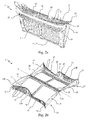
- Figures 2a and 2b represent, respectively, a first and a second perspective view of the filter 1, which the support device 200 according to the invention (not shown in figures 2a, 2b ) can be applied to.
- the filter 1 comprises a first frame 10 and a second frame 20 which contain within a filter element F (schematically represented only in figure 2a ), for example comprising a small fine net of porous plastic material, said first 10 and second frame 20 being connected to each other along respective first adjacent edges 11, 21 so that the filter 1 can be opened in a book-like fashion.
- a filter element F Schematically represented only in figure 2a
- connection along said first edges 11, 21 allows said first 10 and second frame 20 to rotate around an axis X, shown in figure 2b with a dash-dot line.
- the particular shape of the filter 1 facilitates the removing operations of impurities or fluff collected within said filter 1; in fact, the possibility to open in a book-like fashion the filter 1 allows easy extraction of the filter element F in order to recondition, in particular, by removing the impurities or fluff that it retained.
- first and second frame 10, 20 comprise respective second edges 12, 22 provided with strips 13, 23, each of said strips 13, 23 comprising:
- said closing position of the filter 1 is shown in figure 2a , while figure 2b shows the filter 1 in an opening position.
- these figures show the first strip 13 comprising a first grabbing hole 14 and the second strip 23 comprising a second grabbing hole 24.
- the particular embodiment described above of the filter 1 allows at the same time to facilitate the removal of the filter 1 from the housing in which it is located inside the drying machine 100, to facilitate the opening operations of the filter 1 and to facilitate the removing operations of impurities or fluff collected within the filter 1 itself.
- the grabbing holes 14, 24 of said strips 13, 23 allow the user to insert the fingers in order both to remove filter 1 from the drying machine 100 and in order to obtain a disengagement of the engagement means 15, 25 and get the opening of the filter 1.
- the user in order to obtain this opening the user will merely need to carry out a mutual separation movement of the holes 14, 24 so as to obtain the release of said engagement means 15, 25.
- said engagement means comprise:
- said at least one protrusion 15 is associated with a free end 13E of the first strip 13 and said at least one recess 25 is associated with a free end 23E of the second strip 23.
- said at least one protrusion 15 is formed on a upper face 13S of the first strip 13, in particular next to the free end 13E of the first strip 13; in a complementary way, said at least one recess 25 is formed on a lower face 23' of said second strip 23, in particular next to the free end 23E of the second strip 23.
- first 13 and second strip 23 can comprise a plurality of protrusions 15 and/or recesses 25; in addition, each of said first 13 and second strip 23 can comprise one or more protrusions 15 and/or one or more recesses 25.
- said first 13 and second strip 23 comprise corresponding parts 16, 26 that allow to maintain the correct alignment between the first 10 and second frame 20 when the filter 1 is closed (as shown in figure 2a ).
- the corresponding parts comprise:
- first 13 and second strip 23 may be realized as a single piece respectively with said first 10 and second frame 20, for example during the molding operations of said first 10 and second frame 20, which are usually made of plastic material such as, for example, polypropylene approximately 30% talc filled; alternatively, said first 13 and second strip 23 may be realized separately from the first 10 and second frame 20 and then be associated with them.
- said first and second strips 13, 23 are positioned substantially perpendicularly to said first 10 and second frame 20.
- the free ends 13E, 23E of said first 13 and second strip 23 are wavy type, in such a way as to increase the mutual contact surface.
- each of said strips 13, 23 has a plurality of slots 17, 27, in particular in order to allow adequate air flow coming from the drum 102 of the drying machine 100.
- the filter 1 has a substantially V-shaped section, that is to say, it is realized in such a manner as to have a maximum width at said second edges 12, 22 and/or of said strips 13, 23; the width of said filter 1 progressively decreases up to a minimum value next to said first edges 11, 21.
- first 10 and/or the second frame 20 have side walls 18, 28 (visible in particular in figures 2b , 3a and 3b ) presenting reduced width in the proximity of said first edges 11, 21.
- the strips 13, 23 are associated with said first 10 and second frame 20 at opposite ends with respect to first edges 11, 21; however, it is clear that it is not necessary that said second edges 12, 22 correspond to the ends of said first 10 and second frame 20 opposite with respect to first edges 11, 21. As a result, it is clear that the strips 13, 23 can be associated to different points with respect to the ends of said first 10 and second frame 20.
- the filter 1 is positioned below the opening that can be occluded by door 103 of the drying machine 100, in such a way as to be easily accessible by a user as a result of the opening of said door 103; preferably, said filter 1 is housed in a duct C for the recirculation of air inside the drying machine 100.
- the filter 1 can be associated with one or more cartridges (such as perfuming cartridges) by means of a suitable support device 200 in order to perfume the air introduced into the drum 102 and give therefore a particularly pleasant perfume to cloths loaded in the drum 102 itself.
- cartridges such as perfuming cartridges
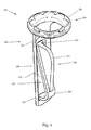
- the device 200 ( figures 4-8 ) comprises a support structure 210 adapted to support a perfuming cartridge 300 housed in said support structure 210.
- the perfuming substance contained in the at least one perfuming cartridge 300 may be present in liquid form confined by at least one wall permeable to the perfume particles released from said perfuming substance.
- the perfuming substance may be in solid form, in gel form or even in powder form.
- the support structure 210 comprises a first portion 220 and a second portion 230.
- the first and second portion 220, 230 cooperate to form a housing 240 for said cartridge 300.
- the first portion 220 has an elongated shape, having a first end 221 and a second end 222.
- the first portion 220 has a window 223 which helps the fragrance to be spread in the filter 1 when the cartridge 300 is inserted in the support structure 210.
- the window 223 extends between the first end 221 and the second end 222 of the first portion 220.
- the second portion 230 has an elongated shape, having a first end 231 and a second end 232.
- the second portion 230 can be or comprise an L-shaped structure, the first end 231 being located on the longer part of the L-shaped structure, the second end 232 being located on the shorter part of the L-shaped structure.
- the second end 222 of the first portion 220 is engaged with the second end 232 of the second portion 230 so as to allow the second portion 230 to be moved relative to the first portion 220.
- the second portion 230 can rotate relative to the first portion 220, in particular along an axis X ( figure 5 ) that is substantially perpendicular to the longitudinal extension of the first and second portions 220, 230.
- the engagement between the second end 222 of the first portion 220 and the second end 232 of the second portion 230 is a resilient engagement.
- the second portion 230 is movable, relative to the first portion 220, between a first position and a second position.
- the cartridge 300 is housed in the housing 240.
- the second portion 230 when the second portion 230 is in the second position, it is moved to some extent away from the first portion 220, so as to keep the cartridge 300 housed in the housing 240.
- the first end 231 of the second portion 230 when the second portion 230 is in the first position, the first end 231 of the second portion 230 is in a comparatively closer position to the first end 221 of the first portion 220; when the second portion 230 is in the second position, the first end 231 of the second portion 230 is in a comparatively farther position from the first end 221 of the first portion 220.
- the engagement between the first and second portions 220, 230 tends to keep or bring the second portion 230 in its first position when no cartridge is housed in the housing 240.
- the cartridge 300 can be kept constrained to the support structure 210 in a sufficiently secure manner.
- the expression “in a sufficiently secure manner” means capable of resisting to the vibrations generated by the machine 100 during operation thereof.
- the latter maintains its position in the housing 240, the vibrations of the machine 100 notwithstanding.
- the second portion 230 in its second position pushes the cartridge 300 against the first portion 220.
- the second portion 230 can be moved between the first position and the second position, and in particular from the first position to the second position, by a force applied by a user.
- the second portion 230 can be provided with a gripping element 233 which allows the user to grab the second portion 230 and displace it between the first and second position.
- the gripping element 233 extends between the first end 231 and the second end 232 of the second portion 230.
- the second portion 230 can be also displaced, in particular through the gripping element 233, in a third position (not shown), wherein it is sufficiently distant from the first portion 220 to allow an easy insertion of the cartridge 300 in the housing 240.
- the removal of the cartridge 300 can be carried out either bringing the second portion 230 back in the third position and picking the cartridge 300 from the housing, or simply by pulling the same cartridge 330 in a direction substantially parallel to the planar extension thereof and substantially perpendicular to the longitudinal extension of the first portion 210, without bringing the second portion 230 in the third position, and having the same second portion 230 directly move from the second position to the first position.
- the support structure 210 is adapted to be removably mounted to the air filter 1.
- the support structure 210 can be adapted to engage into one of the holes 14, 24 of said filter 1.
- the support device 200 further comprises an engaging portion 250 for engagement with the filter 1; the engaging portion 250 is associable with the filter 1 by inserting at least a part of the device 200 towards the inside of the filter 1 from the outside thereof.
- the engaging portion 250 comprises a collar 251 adapted to be coupled to a corresponding hole 14, 24 of the filter 1.
- the collar 251 has a larger diameter than the hole 14, 24 so as to abut against the surface surrounding the hole 14, 24 when the support structure 210 in inserted in the same hole 14, 24.
- the collar 251 substantially extends on a plane that is substantially perpendicular to the direction along which the first portion 220 extends.
- the first portion 220 is connected with the engaging portion 250 at its first end 221.
- the cartridge 300 shown in figure 8 has a substantially discoid shape; however, it is to be noted that the present invention can be suitably employed with cartridges of any shape.
- the support structure 210 further comprises a protrusion 260, which forms an engaging surface extending in a direction substantially parallel to the planar extension of the collar 251.
- the protrusion 260 cooperates with the collar 251 in order to engage the structure of the filter 1 surrounding one of the filter's holes 14, 24 and keep the support device 200 in place when inserted in one of said holes 14, 24.
- the protrusion 260 and the collar 251 form a seat S in which the filter 1 is crimped when the support device 200 is mounted in the same filter 1.
- the protrusion 260 has a horizontal (i.e. parallel to the collar 251) length that decreases moving away from the collar 251, in order not to hinder the insertion of the support device 200 into the filter 1.
- the support device 200 is realized in a material capable of maintaining its structural and mechanical properties up to about 120°C.
- the support device 200 can be effectively employed both in machines based on a ventilation technique and machines based on a condensation technique.
- the support device 200 can be realized in polypropylene with 30% glass reinforcement.
Landscapes
- Engineering & Computer Science (AREA)
- Textile Engineering (AREA)
- Detail Structures Of Washing Machines And Dryers (AREA)
Abstract
Description
- The present invention relates to a support device, particularly adapted to support perfuming cartridges for air filters of drying or washing/drying machines.
- The present invention also relates to an air filter for drying or washing/drying machines provided with such support device, as well as a drying or washing/drying machine, comprising said air filter.
- Drying machines are per se known and normally comprise a drum in which clothes are accommodated that are dried by an air flow generated by a fan and heated by an electrical resistor or a condenser device in a machine with heat pump.
- The hot air flow passes through the clothes in the drum, subtracting the moisture, and then passes through a filter to remove any possible impurities or fluff in the same airflow.
- Moreover, said air flow passes through a heat exchanger, where it cools as a result of the heat exchange with more fresh ambient air. The air flow thus condenses and releases water that flows into a drip tray usually placed in the bottom part of the machine; from the drip tray, the water is carried by a pump into a removable container normally located in the upper part of the machine, in a position that is easily accessible by a user, which provides for removal and the periodic emptying of said container.
- It is clear that the drying machines known to the state of the art may also be devoid of the drip tray; in such cases, they present only the container for collecting the condensed water, said container being usually placed in the bottom part of the machine itself.
- Machines are also known in which the moist air coming from the drum does not condense, but it is discharged outside the machine.
- As a result, the drying machines known to the state of the art comprise:
- a frame that accommodates a drum for the containment of the clothes to dry,
- first means for the passage of heated air through the drum,
- a filter to remove impurities or fluff in the air flow coming from the drum.
- In addition, these drying machines can also include heat exchanger means crossed by the air coming from the drum, which can be optionally associated with a container for collecting the condensed water.
- In particular, it is known a filter adapted to eliminate impurities or fluff in the air flow. Usually, this filter has an opening that facilitates the entrance into the filter of the entire air flow coming from the drum, in such a way as to obtain the elimination of impurities or fluff in such airflow. Furthermore, this filter is generally shaped in such a way as to be placed inside a dedicated housing of the machine, usually formed below the inlet of the drum.
- European patent specification
EP 2 749 687 B1 , in the name of the same Applicant, discloses a perfuming system, adapted to be associated to said filter in order to perfume the air used for drying the clothes and make more pleasant the sensation of wearing said clothes once completed the drying step. - In this context, the Applicant has realized that it would be desirable to provide the perfuming systems with a support element having a simplified structure and permitting a quick and simple removal/replacement of the perfuming cartridge.
- It is an object of the present invention to provide a support device, in particular adapted to support cartridges such as perfuming cartridges for air filters of drying or washing/drying machines, that has a simple and low cost structure and, at the same time, does not require substantial changes to the structure of the filter to be used.
- Another object of the present invention is to provide a support device which allows replacement of cartridges in a simple and easy way, in particular without requiring that the support be removed from the filter.
- Another object of the present invention is to provide a support device which can be easily applicable to already existing filters, without requiring structural changes in the filter. These and further objects are substantially achieved by a support device as described in the appended claims.
- The basic idea of the present invention is to realize a support device comprising two portions movable relative to each other, so as to obtain a housing wherein a cartridge can be inserted and kept.
- According to one aspect, the invention refers to a support device for drying or washing/drying machines, comprising: a support structure adapted to support at least a cartridge, the latter being preferably a perfuming cartridge, wherein said support structure comprises a first portion and a second portion, said first and second portions defining a housing for at least one cartridge, wherein said second portion is movable relative to said first portion between a first position in which no cartridge is housed in said housing, and a second position in which it a cartridge is housed in said housing.
- Preferably said first portion has an elongated shape having a first end and a second end. Preferably said second portion has an elongated shape having a first end and a second end. Preferably the second end of the first portion is engaged with the second end of the second portion so as to allow said second portion to be moved between said first and second positions.
- Preferably said first portion and said second portion are resiliently engaged to each other. Preferably the engagement between the first portion and the second portion tends to keep or bring said second portion in said first position when no cartridge is housed in said housing.
- Preferably the engagement between the first portion and the second portion tends to keep the cartridge housed in said housing when the second portion is in the second position. Preferably said second portion can be moved in said second position by a force applied by a user.
- Preferably, when the second portion is in the first position, the first end of the second portion is in a comparatively closer position to the first end of the first portion and, when the second portion is in the second position, the first end of the second portion is in a comparatively farther position from the first end of the first portion.
- Preferably said second portion comprises a gripping element to allow a user to grab said second portion and displace it between the first and second position.
- Preferably said support structure is adapted to be removably mounted to an air filter of a drying or washing/drying machine.
- Preferably said support structure is adapted to engage into a hole of said filter.
- Preferably said support device is realized in polypropylene with 30% glass reinforcement. Preferably said support device further comprises an engaging portion for engagement with said filter, said engaging portion being associable with said filter by inserting at least a part of said device towards the inside of said filter from the outside thereof.
- Preferably said engaging portion comprises a collar adapted to be coupled to a corresponding hole of said filter.
- Preferably said support structure further comprises a protrusion, forming an engaging surface extending in a direction substantially parallel to the planar extension of said collar, said protrusion cooperating with said collar in order to engage said filter.
- According to a further aspect, the invention refers to an air filter for drying or washing/drying machines, comprising said support device.
- According to a further aspect, the invention refers to a machine adapted to carry out at least one drying cycle, said machine being a drying machine or a washing/drying machine, comprising said filter.
- Some examples of preferred and advantageous embodiments are described for purely illustrative and non limiting purposes, with reference to the attached drawings, in which:
-
figure 1 shows a block diagram of a drying machine according to the invention; -
figures 2a and 2b represent, respectively, a first and a second perspective view of a filter for removing impurities or fluff present in the air flow of the drying machine offigure 1 ; -
figures 3a and 3b are respectively a perspective view of a first and a second detail of the filter offigures 2a and 2b ; -
figure 4 shows a perspective view of a support device according to the invention; -
figure 5 shows a rear view of the support device offigure 4 ; -
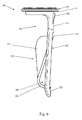
figure 6 shows a side view of the support device offigure 4 ; -
figure 7 shows a plant view of the support device offigure 4 ; -
figure 8 shows a perspective view of the support device offigure 4 wherein a cartridge is housed. - With reference to the attached figures, with 200 has been generally indicated a support device according to the invention; with 1 has been indicated a filter according to the invention and with 100 has been indicated a drying machine according to the invention. The following description will refer to, for purely illustrative purpose, a drying machine. However, it should be understood that the invention also extends in a similar manner to a washing/drying machine.
- The drying machine 100 (
figure 1 ) comprises acasing 101 which houses adrum 102 for containing clothes (not shown) to dry, saiddrum 102 being accessible from the outside through adoor 103 usually provided with gaskets (not shown). - In addition, the
drying machine 100 includes firstmeans drum 102. In particular, said first means can comprise anelectrical resistor 104 and a fan 105 (as shown infigure 1 ), or a heat pump. - The
drying machine 100 also comprisessecond means 106 for heat exchange that is crossed by the air coming from thedrum 102; preferably, said second means comprises anexchanger 106 where the moist air coming from thedrum 102 condenses. - The
drying machine 100 further comprises at least onecontainer 107 for collecting the condensed water produced by saidsecond means 106. - In particular, at the outlet of the
drum 102 moist air passes through afilter 1 to eliminate the impurities or fluff in the air flow; then the hot and moist air is cooled by heat exchange with fresh air (normally at ambient temperature) in saidsecond means 106, said fresh air possibly being carried by a second fan (not shown infigure 1 ). - The condensed water contained into a
drip tray 108 is pumped by apump 109 in thecontainer 107, where it is collected. However, it is clear that the dryingmachine 100 according to the present invention may also have thecontainer 107 in the bottom part of themachine 100; in this case, the dryingmachine 100 can also be devoid of thedrip tray 108 and/or pump 109. - If the
machine 100 provides for a vented drying process, there would not be condensation of the moist air and the machine would not then be provided with thedrip tray 108, thepump 109 and thecontainer 107. The moist air would be in fact evacuated outside the machine through suitable canalization. - The above description is a basic schematic description of a drying machine, aimed at explaining how it works; in reality the drying
machine 100 may be provided with further components that in this description are omitted for sake of simplicity. -
Figures 2a and 2b represent, respectively, a first and a second perspective view of thefilter 1, which thesupport device 200 according to the invention (not shown infigures 2a, 2b ) can be applied to. - In these figures it can be seen that the
filter 1 comprises afirst frame 10 and asecond frame 20 which contain within a filter element F (schematically represented only infigure 2a ), for example comprising a small fine net of porous plastic material, said first 10 andsecond frame 20 being connected to each other along respective firstadjacent edges filter 1 can be opened in a book-like fashion. - Substantially, the connection along said first edges 11, 21 allows said first 10 and
second frame 20 to rotate around an axis X, shown infigure 2b with a dash-dot line. - The particular shape of the
filter 1 facilitates the removing operations of impurities or fluff collected within saidfilter 1; in fact, the possibility to open in a book-like fashion thefilter 1 allows easy extraction of the filter element F in order to recondition, in particular, by removing the impurities or fluff that it retained. - Preferably, the first and
second frame second edges strips - a grabbing
hole - engagement means 15, 25 to keep in a closed condition the
filter 1. - In particular, said closing position of the
filter 1 is shown infigure 2a , whilefigure 2b shows thefilter 1 in an opening position. Moreover, these figures show thefirst strip 13 comprising a first grabbinghole 14 and thesecond strip 23 comprising a second grabbinghole 24. - The particular embodiment described above of the
filter 1 allows at the same time to facilitate the removal of thefilter 1 from the housing in which it is located inside the dryingmachine 100, to facilitate the opening operations of thefilter 1 and to facilitate the removing operations of impurities or fluff collected within thefilter 1 itself. - In fact, the grabbing
holes filter 1 from the dryingmachine 100 and in order to obtain a disengagement of the engagement means 15, 25 and get the opening of thefilter 1. In particular, in order to obtain this opening the user will merely need to carry out a mutual separation movement of theholes - In particular, said engagement means comprise:
- at least one
protrusion 15 associated with thefirst strip 13 of thefirst frame 10; - at least a
recess 25 formed on thesecond strip 23 of thesecond frame 20, saidrecess 25 being adapted to receive theprotrusion 15 of thefirst strip 13 of thefirst frame 10. - In
figures 3a and 3b , which respectively represent a perspective top view of the first frame 10 (and the first strip 13) and a perspective bottom view of the second frame 20 (and the second strip 23), said at least oneprotrusion 15 and at least onerecess 25 can be observed in greater detail. - In particular, from
figures 2b ,3a and 3b can be seen that said at least oneprotrusion 15 is associated with afree end 13E of thefirst strip 13 and said at least onerecess 25 is associated with afree end 23E of thesecond strip 23. - Preferably, said at least one
protrusion 15 is formed on aupper face 13S of thefirst strip 13, in particular next to thefree end 13E of thefirst strip 13; in a complementary way, said at least onerecess 25 is formed on a lower face 23' of saidsecond strip 23, in particular next to thefree end 23E of thesecond strip 23. - It is clear that the first 13 and
second strip 23 can comprise a plurality ofprotrusions 15 and/or recesses 25; in addition, each of said first 13 andsecond strip 23 can comprise one ormore protrusions 15 and/or one or more recesses 25. - In a preferred embodiment, said first 13 and
second strip 23 comprise correspondingparts second frame 20 when thefilter 1 is closed (as shown infigure 2a ). In particular, the corresponding parts comprise: - an
opening 16 formed on thefirst strip 13, in particular next to thefree end 13E of thefirst strip 13; - a
tooth 26 formed on thesecond strip 23 and adapted to be inserted in saidopening 16, in particular, saidtooth 26 being formed next to thefree end 23E of thesecond strip 23. - In addition, the first 13 and
second strip 23 may be realized as a single piece respectively with said first 10 andsecond frame 20, for example during the molding operations of said first 10 andsecond frame 20, which are usually made of plastic material such as, for example, polypropylene approximately 30% talc filled; alternatively, said first 13 andsecond strip 23 may be realized separately from the first 10 andsecond frame 20 and then be associated with them. - Preferably, said first and
second strips second frame 20. - In a preferred embodiment, the free ends 13E, 23E of said first 13 and
second strip 23 are wavy type, in such a way as to increase the mutual contact surface. - In addition, each of said strips 13, 23 has a plurality of
slots drum 102 of the dryingmachine 100. - Preferably, the
filter 1 has a substantially V-shaped section, that is to say, it is realized in such a manner as to have a maximum width at saidsecond edges filter 1 progressively decreases up to a minimum value next to said first edges 11, 21. - For this purpose, preferably the first 10 and/or the
second frame 20 haveside walls 18, 28 (visible in particular infigures 2b ,3a and 3b ) presenting reduced width in the proximity of said first edges 11, 21. - In the attached drawings, the
strips second frame 20 at opposite ends with respect tofirst edges second frame 20 opposite with respect tofirst edges strips second frame 20. - As shown, in particular in
figure 1 , thefilter 1 is positioned below the opening that can be occluded bydoor 103 of the dryingmachine 100, in such a way as to be easily accessible by a user as a result of the opening of saiddoor 103; preferably, saidfilter 1 is housed in a duct C for the recirculation of air inside the dryingmachine 100. - According to the invention, the
filter 1 can be associated with one or more cartridges (such as perfuming cartridges) by means of asuitable support device 200 in order to perfume the air introduced into thedrum 102 and give therefore a particularly pleasant perfume to cloths loaded in thedrum 102 itself. - The device 200 (
figures 4-8 ) comprises asupport structure 210 adapted to support a perfumingcartridge 300 housed in saidsupport structure 210. - The perfuming substance contained in the at least one perfuming
cartridge 300 may be present in liquid form confined by at least one wall permeable to the perfume particles released from said perfuming substance. Alternatively the perfuming substance may be in solid form, in gel form or even in powder form. - In more detail, the
support structure 210 comprises afirst portion 220 and asecond portion 230. - The first and
second portion housing 240 for saidcartridge 300. - Preferably, the
first portion 220 has an elongated shape, having afirst end 221 and asecond end 222. - Advantageously, the
first portion 220 has awindow 223 which helps the fragrance to be spread in thefilter 1 when thecartridge 300 is inserted in thesupport structure 210. Preferably thewindow 223 extends between thefirst end 221 and thesecond end 222 of thefirst portion 220. - Preferably, the
second portion 230 has an elongated shape, having afirst end 231 and asecond end 232. - The
second portion 230 can be or comprise an L-shaped structure, thefirst end 231 being located on the longer part of the L-shaped structure, thesecond end 232 being located on the shorter part of the L-shaped structure. - The
second end 222 of thefirst portion 220 is engaged with thesecond end 232 of thesecond portion 230 so as to allow thesecond portion 230 to be moved relative to thefirst portion 220. - Preferably the
second portion 230 can rotate relative to thefirst portion 220, in particular along an axis X (figure 5 ) that is substantially perpendicular to the longitudinal extension of the first andsecond portions - For example, the engagement between the
second end 222 of thefirst portion 220 and thesecond end 232 of thesecond portion 230 is a resilient engagement. - According to the invention, the
second portion 230 is movable, relative to thefirst portion 220, between a first position and a second position. - In the first position (
figure 4 ), no cartridge is housed in thehousing 240. - In the second position (
figure 8 ), thecartridge 300 is housed in thehousing 240. - In practical terms, when the
second portion 230 is in the second position, it is moved to some extent away from thefirst portion 220, so as to keep thecartridge 300 housed in thehousing 240. - Preferably, when the
second portion 230 is in the first position, thefirst end 231 of thesecond portion 230 is in a comparatively closer position to thefirst end 221 of thefirst portion 220; when thesecond portion 230 is in the second position, thefirst end 231 of thesecond portion 230 is in a comparatively farther position from thefirst end 221 of thefirst portion 220. - Advantageously, the engagement between the first and
second portions second portion 230 in its first position when no cartridge is housed in thehousing 240. - When a
cartridge 300 is housed in thehousing 240, i.e. when thesecond portion 230 is in the second position, the engagement between thefirst portion 220 and thesecond portion 230 tends to keep thecartridge 300 housed in saidhousing 240. - Accordingly, the
cartridge 300 can be kept constrained to thesupport structure 210 in a sufficiently secure manner. - It is to be noted that, in the present description, the expression "in a sufficiently secure manner" means capable of resisting to the vibrations generated by the
machine 100 during operation thereof. In other terms, thanks to the engagement between the first andsecond portions cartridge 300, the latter maintains its position in thehousing 240, the vibrations of themachine 100 notwithstanding. - In particular, the
second portion 230 in its second position pushes thecartridge 300 against thefirst portion 220. - Preferably, the
second portion 230 can be moved between the first position and the second position, and in particular from the first position to the second position, by a force applied by a user. - In particular, the
second portion 230 can be provided with agripping element 233 which allows the user to grab thesecond portion 230 and displace it between the first and second position. - Preferably the
gripping element 233 extends between thefirst end 231 and thesecond end 232 of thesecond portion 230. - Preferably, the
second portion 230 can be also displaced, in particular through thegripping element 233, in a third position (not shown), wherein it is sufficiently distant from thefirst portion 220 to allow an easy insertion of thecartridge 300 in thehousing 240. - In summary, the operation of the
second portion 230 can be summarized as follows: - the
second portion 230 is initially in the first position; - the user acts on the
second portion 230 through thegripping element 233, and brings the samesecond portion 230 in the third position; - the user inserts the
cartridge 300; - the user releases (or drives) the
second portion 230 so as to let the latter reach the second position. - It is to be noted that the removal of the
cartridge 300 can be carried out either bringing thesecond portion 230 back in the third position and picking thecartridge 300 from the housing, or simply by pulling the same cartridge 330 in a direction substantially parallel to the planar extension thereof and substantially perpendicular to the longitudinal extension of thefirst portion 210, without bringing thesecond portion 230 in the third position, and having the samesecond portion 230 directly move from the second position to the first position. - Preferably, the
support structure 210 is adapted to be removably mounted to theair filter 1. In particular, thesupport structure 210 can be adapted to engage into one of theholes filter 1. - Preferably the
support device 200 further comprises an engagingportion 250 for engagement with thefilter 1; the engagingportion 250 is associable with thefilter 1 by inserting at least a part of thedevice 200 towards the inside of thefilter 1 from the outside thereof. - In more detail, the engaging
portion 250 comprises acollar 251 adapted to be coupled to a correspondinghole filter 1. Thecollar 251 has a larger diameter than thehole hole support structure 210 in inserted in thesame hole - Preferably, as shown in the attached drawings, the
collar 251 substantially extends on a plane that is substantially perpendicular to the direction along which thefirst portion 220 extends. - Preferably, the
first portion 220 is connected with the engagingportion 250 at itsfirst end 221. - The
cartridge 300 shown infigure 8 has a substantially discoid shape; however, it is to be noted that the present invention can be suitably employed with cartridges of any shape. Preferably, thesupport structure 210 further comprises aprotrusion 260, which forms an engaging surface extending in a direction substantially parallel to the planar extension of thecollar 251. - Advantageously, the
protrusion 260 cooperates with thecollar 251 in order to engage the structure of thefilter 1 surrounding one of the filter'sholes support device 200 in place when inserted in one of saidholes - In particular, the
protrusion 260 and thecollar 251 form a seat S in which thefilter 1 is crimped when thesupport device 200 is mounted in thesame filter 1. - Preferably, the
protrusion 260 has a horizontal (i.e. parallel to the collar 251) length that decreases moving away from thecollar 251, in order not to hinder the insertion of thesupport device 200 into thefilter 1. - It is to be noted that other engaging techniques, such as for example threaded surfaces, bayonet coupling, etc. can be used as an alternative to the
protrusion 260. - Preferably the
support device 200 is realized in a material capable of maintaining its structural and mechanical properties up to about 120°C. - Accordingly, the
support device 200 can be effectively employed both in machines based on a ventilation technique and machines based on a condensation technique. - For example, the
support device 200 can be realized in polypropylene with 30% glass reinforcement.
Claims (15)
- Support device for drying or washing/drying machines, comprising: a support structure (210) adapted to support at least a cartridge (300), the latter being preferably a perfuming cartridge, wherein said support structure (210) comprises a first portion (220) and a second portion (230), said first and second portions (220, 230) defining a housing (240) for at least one cartridge, wherein said second portion (230) is movable relative to said first portion (220) between a first position in which no cartridge is housed in said housing (240), and a second position wherein it is capable of keeping at least one cartridge housed in said housing (240).
- Support device according to claim 1 wherein said first portion (220) has an elongated shape having a first end (221) and a second end (222), said second portion (230) having an elongated shape having a first end (231) and a second end (232), wherein the second end (222) of the first portion (220) is engaged with the second end (232) of the second portion (230) so as to allow said second portion (230) to be moved between said first and second positions.
- Support device according to claim 1 or 2 wherein said first portion (220) and said second portion (230) are resiliently engaged to each other.
- Support device according to anyone of the preceding claims wherein the engagement between said first portion (220) and said second portion (230) tends to keep or bring said second portion (230) in said first position when no cartridge is housed in said housing (240).
- Support device according to anyone of the preceding claims wherein the engagement between the first portion (220) and the second portion (230) tends to keep the cartridge (300) housed in said housing (240) when the second portion (230) is in the second position.
- Support device according to anyone of the preceding claims wherein said second portion (230) can be moved in said second position by a force applied by a user.
- Support device according to anyone of the preceding claims wherein, when the second portion (230) is in the first position, the first end (231) of the second portion (230) is in a comparatively closer position to the first end (221) of the first portion (220) and, when the second portion (230) is in the second position, the first end (231) of the second portion (230) is in a comparatively farther position from the first end (221) of the first portion (220).
- Support device according to anyone of the preceding claims wherein said second portion (230) comprises a gripping element (233) to allow a user to grab said second portion (230) and displace it between the first and second position.
- Support device according to anyone of the preceding claims wherein said support structure (210) is adapted to be removably mounted to an air filter (1) of a drying or washing/drying machine (100), said support structure (210) being preferably adapted to engage into a hole (14, 24) of said filter (1).
- Support device according to anyone of the preceding claims wherein said support device (1) is realized in polypropylene with 30% glass reinforcement.
- Support device according to anyone of the preceding claims further comprising an engaging portion (250) for engagement with said filter (1), said engaging portion (250) being associable with said filter (1) by inserting at least a part of said device (200) towards the inside of said filter (1) from the outside thereof.
- Support device according to claim 11, wherein said engaging portion (250) comprises a collar (251) adapted to be coupled to a corresponding hole (14, 24) of said filter (1).
- Support device according to claim 12 wherein said support structure (210) further comprises a protrusion (260), forming an engaging surface extending in a direction substantially parallel to the planar extension of said collar (251), said protrusion (260) cooperating with said collar (251) in order to engage said filter (1).
- An air filter (1) for drying or washing/drying machines (100), comprising a support device (200) according to any one of the preceding claims.
- A machine (100) adapted to carry out at least one drying cycle, said machine (100) being a drying machine or a washing/drying machine, comprising a filter (1) according to claim 14.
Priority Applications (1)
| Application Number | Priority Date | Filing Date | Title |
|---|---|---|---|
| EP15174848.0A EP3112526B1 (en) | 2015-07-01 | 2015-07-01 | Support device for air filters for drying or washing/drying machines, air filter for drying machines or washing/drying machines provided with said support device and drying or washing/drying machine provided with said filter |
Applications Claiming Priority (1)
| Application Number | Priority Date | Filing Date | Title |
|---|---|---|---|
| EP15174848.0A EP3112526B1 (en) | 2015-07-01 | 2015-07-01 | Support device for air filters for drying or washing/drying machines, air filter for drying machines or washing/drying machines provided with said support device and drying or washing/drying machine provided with said filter |
Publications (2)
| Publication Number | Publication Date |
|---|---|
| EP3112526A1 true EP3112526A1 (en) | 2017-01-04 |
| EP3112526B1 EP3112526B1 (en) | 2020-10-14 |
Family
ID=53514021
Family Applications (1)
| Application Number | Title | Priority Date | Filing Date |
|---|---|---|---|
| EP15174848.0A Not-in-force EP3112526B1 (en) | 2015-07-01 | 2015-07-01 | Support device for air filters for drying or washing/drying machines, air filter for drying machines or washing/drying machines provided with said support device and drying or washing/drying machine provided with said filter |
Country Status (1)
| Country | Link |
|---|---|
| EP (1) | EP3112526B1 (en) |
Cited By (1)
| Publication number | Priority date | Publication date | Assignee | Title |
|---|---|---|---|---|
| CN113684655A (en) * | 2021-08-30 | 2021-11-23 | 无锡小天鹅电器有限公司 | Air inlet grille of clothes treatment device and clothes treatment device |
Citations (7)
| Publication number | Priority date | Publication date | Assignee | Title |
|---|---|---|---|---|
| WO2003069043A1 (en) * | 2002-02-13 | 2003-08-21 | The Procter & Gamble Company | Sequential dispensing of laundry additives during automatic machine laundering of fabrics |
| US20050050762A1 (en) * | 2003-08-18 | 2005-03-10 | Hood Lisa J. | Volatilizable media holder for a laundry dryer |
| US20050102767A1 (en) * | 2002-02-13 | 2005-05-19 | The Procter & Gamble Company | Universal dispenser for dispensing of laundry additives during automatic machine laundering of fabrics |
| EP1932964A1 (en) * | 2006-12-15 | 2008-06-18 | LG Electronics Inc. | Laundry machine |
| EP2669422A1 (en) * | 2012-05-31 | 2013-12-04 | Miele & Cie. KG | Drying device for drying laundry with a container for holding and dispensing an aromatic substance |
| EP2669423A1 (en) * | 2012-05-31 | 2013-12-04 | Miele & Cie. KG | Drying device for drying laundry with a container for holding and dispensing an aromatic substance |
| EP2749687B1 (en) | 2012-12-27 | 2015-04-01 | Indesit Company S.p.A. | Support device for air filters for drying or washing/drying machines, air filter for drying machines or washing/drying machines provided with said support device and drying or washing/drying machine provided with said filter |
Family Cites Families (1)
| Publication number | Priority date | Publication date | Assignee | Title |
|---|---|---|---|---|
| WO2005077246A1 (en) * | 2004-02-13 | 2005-08-25 | BSH Bosch und Siemens Hausgeräte GmbH | Device for fitting an object in a dishwasher |
-
2015
- 2015-07-01 EP EP15174848.0A patent/EP3112526B1/en not_active Not-in-force
Patent Citations (7)
| Publication number | Priority date | Publication date | Assignee | Title |
|---|---|---|---|---|
| WO2003069043A1 (en) * | 2002-02-13 | 2003-08-21 | The Procter & Gamble Company | Sequential dispensing of laundry additives during automatic machine laundering of fabrics |
| US20050102767A1 (en) * | 2002-02-13 | 2005-05-19 | The Procter & Gamble Company | Universal dispenser for dispensing of laundry additives during automatic machine laundering of fabrics |
| US20050050762A1 (en) * | 2003-08-18 | 2005-03-10 | Hood Lisa J. | Volatilizable media holder for a laundry dryer |
| EP1932964A1 (en) * | 2006-12-15 | 2008-06-18 | LG Electronics Inc. | Laundry machine |
| EP2669422A1 (en) * | 2012-05-31 | 2013-12-04 | Miele & Cie. KG | Drying device for drying laundry with a container for holding and dispensing an aromatic substance |
| EP2669423A1 (en) * | 2012-05-31 | 2013-12-04 | Miele & Cie. KG | Drying device for drying laundry with a container for holding and dispensing an aromatic substance |
| EP2749687B1 (en) | 2012-12-27 | 2015-04-01 | Indesit Company S.p.A. | Support device for air filters for drying or washing/drying machines, air filter for drying machines or washing/drying machines provided with said support device and drying or washing/drying machine provided with said filter |
Cited By (1)
| Publication number | Priority date | Publication date | Assignee | Title |
|---|---|---|---|---|
| CN113684655A (en) * | 2021-08-30 | 2021-11-23 | 无锡小天鹅电器有限公司 | Air inlet grille of clothes treatment device and clothes treatment device |
Also Published As
| Publication number | Publication date |
|---|---|
| EP3112526B1 (en) | 2020-10-14 |
Similar Documents
| Publication | Publication Date | Title |
|---|---|---|
| EP2749687B1 (en) | Support device for air filters for drying or washing/drying machines, air filter for drying machines or washing/drying machines provided with said support device and drying or washing/drying machine provided with said filter | |
| KR101993226B1 (en) | Laundry Treating Apparatus | |
| CN114222838B (en) | laundry treatment device | |
| EP2581489A1 (en) | A heat pump laundry dryer with air stream filters | |
| EP3562988B1 (en) | A laundry dryer comprising a filter assembly and a method to clean a filter assembly | |
| EP2896740A1 (en) | Clothes treating apparatus with heat pump | |
| AU2005203221A1 (en) | Washing machine and lint removing apparatus thereof | |
| EP3392398B1 (en) | Laundry dryer | |
| KR102819442B1 (en) | a laundry treating apparatus | |
| AU2018274956B2 (en) | Laundry Dryer Apparatus | |
| EP2669423B1 (en) | Drying device for drying laundry with a container for holding and dispensing an aromatic substance | |
| JP5292222B2 (en) | Clothes dryer | |
| EP3112526B1 (en) | Support device for air filters for drying or washing/drying machines, air filter for drying machines or washing/drying machines provided with said support device and drying or washing/drying machine provided with said filter | |
| EP2196578B1 (en) | Laundry dryer with removable condenser | |
| CN105308233B (en) | Laundry treatment device with condensate storage tank and method of collecting and draining condensate | |
| EP4389957A1 (en) | Clothing care apparatus | |
| JP2013198756A (en) | Clothing dryer | |
| EP2511414B1 (en) | Filtration system for laundry dryer | |
| ITTO20120611A1 (en) | DRYER MACHINE OR WASHING MACHINE INCLUDING INTERCHANGEABLE MEANS OF REPLACEMENT REPLACEABLE WITH A DRAWER | |
| EP3000929B1 (en) | Lint strainer for laundry care apparatus | |
| EP4386131A1 (en) | Object treatment apparatus | |
| EP2511415B1 (en) | Condenser for laundry drying machine |
Legal Events
| Date | Code | Title | Description |
|---|---|---|---|
| PUAI | Public reference made under article 153(3) epc to a published international application that has entered the european phase |
Free format text: ORIGINAL CODE: 0009012 |
|
| STAA | Information on the status of an ep patent application or granted ep patent |
Free format text: STATUS: THE APPLICATION HAS BEEN PUBLISHED |
|
| AK | Designated contracting states |
Kind code of ref document: A1 Designated state(s): AL AT BE BG CH CY CZ DE DK EE ES FI FR GB GR HR HU IE IS IT LI LT LU LV MC MK MT NL NO PL PT RO RS SE SI SK SM TR |
|
| AX | Request for extension of the european patent |
Extension state: BA ME |
|
| RAP1 | Party data changed (applicant data changed or rights of an application transferred) |
Owner name: WHIRLPOOL EMEA S.P.A |
|
| STAA | Information on the status of an ep patent application or granted ep patent |
Free format text: STATUS: REQUEST FOR EXAMINATION WAS MADE |
|
| 17P | Request for examination filed |
Effective date: 20170627 |
|
| RBV | Designated contracting states (corrected) |
Designated state(s): AL AT BE BG CH CY CZ DE DK EE ES FI FR GB GR HR HU IE IS IT LI LT LU LV MC MK MT NL NO PL PT RO RS SE SI SK SM TR |
|
| STAA | Information on the status of an ep patent application or granted ep patent |
Free format text: STATUS: EXAMINATION IS IN PROGRESS |
|
| 17Q | First examination report despatched |
Effective date: 20180605 |
|
| GRAP | Despatch of communication of intention to grant a patent |
Free format text: ORIGINAL CODE: EPIDOSNIGR1 |
|
| STAA | Information on the status of an ep patent application or granted ep patent |
Free format text: STATUS: GRANT OF PATENT IS INTENDED |
|
| INTG | Intention to grant announced |
Effective date: 20200724 |
|
| GRAS | Grant fee paid |
Free format text: ORIGINAL CODE: EPIDOSNIGR3 |
|
| GRAA | (expected) grant |
Free format text: ORIGINAL CODE: 0009210 |
|
| STAA | Information on the status of an ep patent application or granted ep patent |
Free format text: STATUS: THE PATENT HAS BEEN GRANTED |
|
| AK | Designated contracting states |
Kind code of ref document: B1 Designated state(s): AL AT BE BG CH CY CZ DE DK EE ES FI FR GB GR HR HU IE IS IT LI LT LU LV MC MK MT NL NO PL PT RO RS SE SI SK SM TR |
|
| REG | Reference to a national code |
Ref country code: GB Ref legal event code: FG4D |
|
| REG | Reference to a national code |
Ref country code: AT Ref legal event code: REF Ref document number: 1323670 Country of ref document: AT Kind code of ref document: T Effective date: 20201015 Ref country code: CH Ref legal event code: EP |
|
| REG | Reference to a national code |
Ref country code: DE Ref legal event code: R096 Ref document number: 602015060383 Country of ref document: DE |
|
| REG | Reference to a national code |
Ref country code: IE Ref legal event code: FG4D |
|
| REG | Reference to a national code |
Ref country code: AT Ref legal event code: MK05 Ref document number: 1323670 Country of ref document: AT Kind code of ref document: T Effective date: 20201014 |
|
| REG | Reference to a national code |
Ref country code: NL Ref legal event code: MP Effective date: 20201014 |
|
| PG25 | Lapsed in a contracting state [announced via postgrant information from national office to epo] |
Ref country code: RS Free format text: LAPSE BECAUSE OF FAILURE TO SUBMIT A TRANSLATION OF THE DESCRIPTION OR TO PAY THE FEE WITHIN THE PRESCRIBED TIME-LIMIT Effective date: 20201014 Ref country code: FI Free format text: LAPSE BECAUSE OF FAILURE TO SUBMIT A TRANSLATION OF THE DESCRIPTION OR TO PAY THE FEE WITHIN THE PRESCRIBED TIME-LIMIT Effective date: 20201014 Ref country code: NO Free format text: LAPSE BECAUSE OF FAILURE TO SUBMIT A TRANSLATION OF THE DESCRIPTION OR TO PAY THE FEE WITHIN THE PRESCRIBED TIME-LIMIT Effective date: 20210114 Ref country code: PT Free format text: LAPSE BECAUSE OF FAILURE TO SUBMIT A TRANSLATION OF THE DESCRIPTION OR TO PAY THE FEE WITHIN THE PRESCRIBED TIME-LIMIT Effective date: 20210215 Ref country code: NL Free format text: LAPSE BECAUSE OF FAILURE TO SUBMIT A TRANSLATION OF THE DESCRIPTION OR TO PAY THE FEE WITHIN THE PRESCRIBED TIME-LIMIT Effective date: 20201014 Ref country code: GR Free format text: LAPSE BECAUSE OF FAILURE TO SUBMIT A TRANSLATION OF THE DESCRIPTION OR TO PAY THE FEE WITHIN THE PRESCRIBED TIME-LIMIT Effective date: 20210115 |
|
| REG | Reference to a national code |
Ref country code: LT Ref legal event code: MG4D |
|
| PG25 | Lapsed in a contracting state [announced via postgrant information from national office to epo] |
Ref country code: IS Free format text: LAPSE BECAUSE OF FAILURE TO SUBMIT A TRANSLATION OF THE DESCRIPTION OR TO PAY THE FEE WITHIN THE PRESCRIBED TIME-LIMIT Effective date: 20210214 Ref country code: LV Free format text: LAPSE BECAUSE OF FAILURE TO SUBMIT A TRANSLATION OF THE DESCRIPTION OR TO PAY THE FEE WITHIN THE PRESCRIBED TIME-LIMIT Effective date: 20201014 Ref country code: SE Free format text: LAPSE BECAUSE OF FAILURE TO SUBMIT A TRANSLATION OF THE DESCRIPTION OR TO PAY THE FEE WITHIN THE PRESCRIBED TIME-LIMIT Effective date: 20201014 Ref country code: PL Free format text: LAPSE BECAUSE OF FAILURE TO SUBMIT A TRANSLATION OF THE DESCRIPTION OR TO PAY THE FEE WITHIN THE PRESCRIBED TIME-LIMIT Effective date: 20201014 Ref country code: BG Free format text: LAPSE BECAUSE OF FAILURE TO SUBMIT A TRANSLATION OF THE DESCRIPTION OR TO PAY THE FEE WITHIN THE PRESCRIBED TIME-LIMIT Effective date: 20210114 Ref country code: ES Free format text: LAPSE BECAUSE OF FAILURE TO SUBMIT A TRANSLATION OF THE DESCRIPTION OR TO PAY THE FEE WITHIN THE PRESCRIBED TIME-LIMIT Effective date: 20201014 Ref country code: AT Free format text: LAPSE BECAUSE OF FAILURE TO SUBMIT A TRANSLATION OF THE DESCRIPTION OR TO PAY THE FEE WITHIN THE PRESCRIBED TIME-LIMIT Effective date: 20201014 |
|
| PG25 | Lapsed in a contracting state [announced via postgrant information from national office to epo] |
Ref country code: HR Free format text: LAPSE BECAUSE OF FAILURE TO SUBMIT A TRANSLATION OF THE DESCRIPTION OR TO PAY THE FEE WITHIN THE PRESCRIBED TIME-LIMIT Effective date: 20201014 |
|
| REG | Reference to a national code |
Ref country code: DE Ref legal event code: R097 Ref document number: 602015060383 Country of ref document: DE |
|
| PG25 | Lapsed in a contracting state [announced via postgrant information from national office to epo] |
Ref country code: LT Free format text: LAPSE BECAUSE OF FAILURE TO SUBMIT A TRANSLATION OF THE DESCRIPTION OR TO PAY THE FEE WITHIN THE PRESCRIBED TIME-LIMIT Effective date: 20201014 Ref country code: SK Free format text: LAPSE BECAUSE OF FAILURE TO SUBMIT A TRANSLATION OF THE DESCRIPTION OR TO PAY THE FEE WITHIN THE PRESCRIBED TIME-LIMIT Effective date: 20201014 Ref country code: RO Free format text: LAPSE BECAUSE OF FAILURE TO SUBMIT A TRANSLATION OF THE DESCRIPTION OR TO PAY THE FEE WITHIN THE PRESCRIBED TIME-LIMIT Effective date: 20201014 Ref country code: EE Free format text: LAPSE BECAUSE OF FAILURE TO SUBMIT A TRANSLATION OF THE DESCRIPTION OR TO PAY THE FEE WITHIN THE PRESCRIBED TIME-LIMIT Effective date: 20201014 Ref country code: CZ Free format text: LAPSE BECAUSE OF FAILURE TO SUBMIT A TRANSLATION OF THE DESCRIPTION OR TO PAY THE FEE WITHIN THE PRESCRIBED TIME-LIMIT Effective date: 20201014 Ref country code: SM Free format text: LAPSE BECAUSE OF FAILURE TO SUBMIT A TRANSLATION OF THE DESCRIPTION OR TO PAY THE FEE WITHIN THE PRESCRIBED TIME-LIMIT Effective date: 20201014 |
|
| PLBE | No opposition filed within time limit |
Free format text: ORIGINAL CODE: 0009261 |
|
| STAA | Information on the status of an ep patent application or granted ep patent |
Free format text: STATUS: NO OPPOSITION FILED WITHIN TIME LIMIT |
|
| PG25 | Lapsed in a contracting state [announced via postgrant information from national office to epo] |
Ref country code: DK Free format text: LAPSE BECAUSE OF FAILURE TO SUBMIT A TRANSLATION OF THE DESCRIPTION OR TO PAY THE FEE WITHIN THE PRESCRIBED TIME-LIMIT Effective date: 20201014 |
|
| 26N | No opposition filed |
Effective date: 20210715 |
|
| PG25 | Lapsed in a contracting state [announced via postgrant information from national office to epo] |
Ref country code: AL Free format text: LAPSE BECAUSE OF FAILURE TO SUBMIT A TRANSLATION OF THE DESCRIPTION OR TO PAY THE FEE WITHIN THE PRESCRIBED TIME-LIMIT Effective date: 20201014 |
|
| PG25 | Lapsed in a contracting state [announced via postgrant information from national office to epo] |
Ref country code: SI Free format text: LAPSE BECAUSE OF FAILURE TO SUBMIT A TRANSLATION OF THE DESCRIPTION OR TO PAY THE FEE WITHIN THE PRESCRIBED TIME-LIMIT Effective date: 20201014 |
|
| REG | Reference to a national code |
Ref country code: CH Ref legal event code: PL |
|
| PG25 | Lapsed in a contracting state [announced via postgrant information from national office to epo] |
Ref country code: MC Free format text: LAPSE BECAUSE OF FAILURE TO SUBMIT A TRANSLATION OF THE DESCRIPTION OR TO PAY THE FEE WITHIN THE PRESCRIBED TIME-LIMIT Effective date: 20201014 |
|
| REG | Reference to a national code |
Ref country code: BE Ref legal event code: MM Effective date: 20210731 |
|
| PG25 | Lapsed in a contracting state [announced via postgrant information from national office to epo] |
Ref country code: LI Free format text: LAPSE BECAUSE OF NON-PAYMENT OF DUE FEES Effective date: 20210731 Ref country code: CH Free format text: LAPSE BECAUSE OF NON-PAYMENT OF DUE FEES Effective date: 20210731 |
|
| PG25 | Lapsed in a contracting state [announced via postgrant information from national office to epo] |
Ref country code: IS Free format text: LAPSE BECAUSE OF FAILURE TO SUBMIT A TRANSLATION OF THE DESCRIPTION OR TO PAY THE FEE WITHIN THE PRESCRIBED TIME-LIMIT Effective date: 20210214 Ref country code: LU Free format text: LAPSE BECAUSE OF NON-PAYMENT OF DUE FEES Effective date: 20210701 |
|
| PG25 | Lapsed in a contracting state [announced via postgrant information from national office to epo] |
Ref country code: IE Free format text: LAPSE BECAUSE OF NON-PAYMENT OF DUE FEES Effective date: 20210701 Ref country code: BE Free format text: LAPSE BECAUSE OF NON-PAYMENT OF DUE FEES Effective date: 20210731 |
|
| PG25 | Lapsed in a contracting state [announced via postgrant information from national office to epo] |
Ref country code: HU Free format text: LAPSE BECAUSE OF FAILURE TO SUBMIT A TRANSLATION OF THE DESCRIPTION OR TO PAY THE FEE WITHIN THE PRESCRIBED TIME-LIMIT; INVALID AB INITIO Effective date: 20150701 |
|
| P01 | Opt-out of the competence of the unified patent court (upc) registered |
Effective date: 20230523 |
|
| PG25 | Lapsed in a contracting state [announced via postgrant information from national office to epo] |
Ref country code: CY Free format text: LAPSE BECAUSE OF FAILURE TO SUBMIT A TRANSLATION OF THE DESCRIPTION OR TO PAY THE FEE WITHIN THE PRESCRIBED TIME-LIMIT Effective date: 20201014 |
|
| REG | Reference to a national code |
Ref country code: DE Ref legal event code: R081 Ref document number: 602015060383 Country of ref document: DE Owner name: WHIRLPOOL EMEA S.R.L., IT Free format text: FORMER OWNER: WHIRLPOOL EMEA S.P.A, PERO, IT |
|
| PG25 | Lapsed in a contracting state [announced via postgrant information from national office to epo] |
Ref country code: MK Free format text: LAPSE BECAUSE OF FAILURE TO SUBMIT A TRANSLATION OF THE DESCRIPTION OR TO PAY THE FEE WITHIN THE PRESCRIBED TIME-LIMIT Effective date: 20201014 |
|
| PG25 | Lapsed in a contracting state [announced via postgrant information from national office to epo] |
Ref country code: MT Free format text: LAPSE BECAUSE OF FAILURE TO SUBMIT A TRANSLATION OF THE DESCRIPTION OR TO PAY THE FEE WITHIN THE PRESCRIBED TIME-LIMIT Effective date: 20201014 |
|
| PGFP | Annual fee paid to national office [announced via postgrant information from national office to epo] |
Ref country code: DE Payment date: 20240730 Year of fee payment: 10 |
|
| PGFP | Annual fee paid to national office [announced via postgrant information from national office to epo] |
Ref country code: GB Payment date: 20240724 Year of fee payment: 10 |
|
| PGFP | Annual fee paid to national office [announced via postgrant information from national office to epo] |
Ref country code: FR Payment date: 20240725 Year of fee payment: 10 |
|
| PGFP | Annual fee paid to national office [announced via postgrant information from national office to epo] |
Ref country code: IT Payment date: 20240705 Year of fee payment: 10 |
|
| PG25 | Lapsed in a contracting state [announced via postgrant information from national office to epo] |
Ref country code: TR Free format text: LAPSE BECAUSE OF FAILURE TO SUBMIT A TRANSLATION OF THE DESCRIPTION OR TO PAY THE FEE WITHIN THE PRESCRIBED TIME-LIMIT Effective date: 20201014 |
|
| REG | Reference to a national code |
Ref country code: DE Ref legal event code: R119 Ref document number: 602015060383 Country of ref document: DE |
|
| GBPC | Gb: european patent ceased through non-payment of renewal fee |
Effective date: 20250701 |
|
| PG25 | Lapsed in a contracting state [announced via postgrant information from national office to epo] |
Ref country code: GB Free format text: LAPSE BECAUSE OF NON-PAYMENT OF DUE FEES Effective date: 20250701 |
|
| PG25 | Lapsed in a contracting state [announced via postgrant information from national office to epo] |
Ref country code: DE Free format text: LAPSE BECAUSE OF NON-PAYMENT OF DUE FEES Effective date: 20260203 |
|
| PG25 | Lapsed in a contracting state [announced via postgrant information from national office to epo] |
Ref country code: FR Free format text: LAPSE BECAUSE OF NON-PAYMENT OF DUE FEES Effective date: 20250731 |
|
| PG25 | Lapsed in a contracting state [announced via postgrant information from national office to epo] |
Ref country code: IT Free format text: LAPSE BECAUSE OF NON-PAYMENT OF DUE FEES Effective date: 20250701 |