EP3112511A1 - Method for shed opening in pile fabric loom - Google Patents
Method for shed opening in pile fabric loom Download PDFInfo
- Publication number
- EP3112511A1 EP3112511A1 EP16173760.6A EP16173760A EP3112511A1 EP 3112511 A1 EP3112511 A1 EP 3112511A1 EP 16173760 A EP16173760 A EP 16173760A EP 3112511 A1 EP3112511 A1 EP 3112511A1
- Authority
- EP
- European Patent Office
- Prior art keywords
- warp yarns
- pile
- shed
- picking
- ground warp
- Prior art date
- Legal status (The legal status is an assumption and is not a legal conclusion. Google has not performed a legal analysis and makes no representation as to the accuracy of the status listed.)
- Granted
Links
Images



Classifications
-
- D—TEXTILES; PAPER
- D03—WEAVING
- D03D—WOVEN FABRICS; METHODS OF WEAVING; LOOMS
- D03D39/00—Pile-fabric looms
-
- D—TEXTILES; PAPER
- D03—WEAVING
- D03D—WOVEN FABRICS; METHODS OF WEAVING; LOOMS
- D03D39/00—Pile-fabric looms
- D03D39/22—Terry looms
- D03D39/223—Cloth control
-
- D—TEXTILES; PAPER
- D03—WEAVING
- D03C—SHEDDING MECHANISMS; PATTERN CARDS OR CHAINS; PUNCHING OF CARDS; DESIGNING PATTERNS
- D03C1/00—Dobbies
- D03C1/14—Features common to dobbies of different types
- D03C1/146—Independent drive motor
-
- D—TEXTILES; PAPER
- D03—WEAVING
- D03C—SHEDDING MECHANISMS; PATTERN CARDS OR CHAINS; PUNCHING OF CARDS; DESIGNING PATTERNS
- D03C13/00—Shedding mechanisms not otherwise provided for
- D03C13/02—Shedding mechanisms not otherwise provided for with independent drive motors
Definitions
- the present invention relates to a method for shed opening by ground warp yarns and pile warp yarns in a pile fabric loom.
- Japanese Patent Application Publication No. 2002-173849 discloses a method for weaving a three-pick towel fabric in a cloth-moving pile fabric loom and shedding patterns for the ground warp yarns and the pile warp yarns. Beating of a weft yarn is performed always at a constant position. The cloth fell is moved forward and backward by the terry motion mechanism between the weft beating position and a position frontward of the weft beating position.
- ground warp yarns and pile warp yarns are moved according to the same shedding pattern in one repeat of pile formation. It is noted, however, that the shedding pattern of the pile warp yarns is made by phase-shifting the shedding pattern of the ground warp yarns by one time of picking. Furthermore, the shedding pattern of the ground warp yarns and the shedding pattern of the pile warp yarns have the same cross timing set at a predetermined angular position of the loom (for example, 320 degrees).
- the tension of pile warp yarns is set lower during a period of time that includes the timing of beating a weft yarn inserted in the fast picking. During a period of time that includes the cross timing of the pile warp yarns after the fast picking, the tension of pile warp yarns is set higher so as to improve separation of pile warp yarns and to prevent mispicking due to poor shedding.
- the piles formed by the fast picking may be formed properly by lowering the tension of the pile warp yarns
- the tension of the pile warp yarns increased by the subsequent movement thereof to form a shed tends to cause piles to be formed improperly.
- Such failure in pile formation lowers the height of the resulting piles and hence causes irregular pile, with the result that the quality of pile fabric is reduced.
- a tension roller for adjusting the tension of the pile warp yarns is disposed on the letting-off side of pile warp yarns.
- the pile warp yarns pass through the tension roller and extend toward the cloth fell through the eyelets of the dropper, the healds, and the reed, so that the tension force adjusted by the tension roller is not applied immediately to the pile warp yarns at the cloth fell position because of the resistance by the dropper, the healds, and the reed.
- the use of the above tension roller is not effective to prevent failure in pile formation.
- the present invention is directed to providing a method that prevents failure in pile formation in a pile fabric loom.
- the pile fabric loom includes a plurality of heald frames through which ground warp yarns and pile warp yarns are inserted, a plurality of drive devices driving the respective heald frames, and a shedding controller controlling the drive devices separately so as to open and close a shed of the ground warp yarns and a shed of the pile warp yarns, and forms piles by loose pickings of a plurality of times and fast picking of one time that are performed in conjunction with forward and backward movement of cloth fell.
- the loose picking is followed by the fast picking.
- the method is characterized by setting cross timing to close the shed of the ground warp yarns earlier than cross timing to close the shed of the pile warp yarns at least during a transitional period from the loose picking to the fast picking.
- FIG. 1 showing the pile fabric loom in side view, a ground warp beam 1 is driven by a ground warp let-off motor M2 that is electrically connected to a ground warp let-off controller C2.
- Ground warp yarns TG that are let-off from the ground warp beam 1 with the rotation of the ground warp let-off motor M2 are moved through an arched back guide plate 2 and a tension roller 3 and inserted through a plurality of heald frames 4A, 4B, 4C, 4D and a reed 5.
- the reed 5 is driven by a drive device (not shown) to swing between the solid-line position for weft insertion and the phantom line-position for beating a weft yarn.
- Woven cloth W is moved through an expansion bar 6, a surface roller 7, and guide rollers 8, 9 and taken up by a cloth roller 10.
- Numeral 11 designate a frame 11 of the pile fabric loom that supports the back guide plate 2 and rotatably supports a tension pipe 12.
- the tension pipe 12 has an urging mechanism (not shown) providing urging force to the tension roller 3.
- An upper support arm 13 is fixedly mounted to the tension pipe 12 and supports at the upper end thereof the tension roller 3.
- Tension variation of the ground warp yarn TG caused by shedding of warp yarns is absorbed by the negative easing motion of the tension roller 3 urged by the urging mechanism of the tension pipe 12.
- a lever 14 is fixed to and extends downward from the urging mechanism of the tension pipe 12.
- a rod 15 is pivotally connected to the lower end of the lever 14.
- a load cell 16 is mounted to the rod 15 for detecting the tension of ground warp yarns TG acting on the tension roller 3, and electrically connected to the ground warp let-off controller C2.
- the ground warp let-off controller C2 controls the speed of the ground warp let-off motor M2 based on the comparison of a predetermined reference tension value and data of warp yarn tension detected by the load cell 16.
- a pile warp beam 17 is disposed above the ground warp beam 1.
- the pile warp beam 17 is driven by a pile warp let-off motor M3 that is electrically connected to the pile warp let-off controller C3.
- the pile warp yarns TP that are let off from the pile warp beam 17 are moved through a turning roller 18, a tensioning member 19 and a terry motion roller 20 and inserted through the heald frames 4A, 4B, 4C, 4D and the reed 5.
- the turning roller 18 is rotatably supported by a shaft 22 that is fixed to the frame 11 and has a load cell 21.
- the load cell 21 detects the tension of the pile warp yarns TP and transmits to the pile warp let-off controller C3 a signal of the detected tension.
- the turning roller 18 has at the opposite ends thereof that are not in contact with the pile warp yarns TP a pair of elements (not shown) to be detected.
- a pair of proximity switches 23 (only one being shown) is disposed in facing relation to the above paired elements to be detected.
- the paired proximity switches 23 detect the rotation of the turning roller 18 and transmit detection signals to the pile warp let-off controller C3.
- the pile warp let-off controller C3 controls the speed of the pile warp let-off motor M3 based on the comparison of a predetermined reference tension value and data of warp yarn tension detected by the load cell 21 and also on the detection signals transmitted from the proximity switches 23.
- the tensioning member 19 is supported by a leaf spring 24 fixed to the frame 11. Tension variation of the pile warp yarns TP caused by the warp yarn shed motion is absorbed by the negative easing motion of the tensioning member 19 due to the deflection of the leaf spring 24. In order to form piles securely in the pile fabric loom, the tension of the pile warp yarns TP is set lower than that of the ground warp yarns TG.
- a rocking lever 26 having an upper arm and a lower arm is pivotally supported on a shaft 25, and the terry motion roller 20 is rotatably supported by the upper arm of the rocking lever 26. The lower arm of the rocking lever 26 is pivotally connected to the rod 15.
- a forked intermediate lever 27 is rotatably mounted on a shaft 28 at an intermediate position as viewed in the front-and-rear direction of the pile fabric loom.
- a pile motion mechanism 29 is disposed above the intermediate lever 27.
- the pile motion mechanism 29 has therein a drive unit (not shown) including a ball screw mechanism or a cam mechanism that is driven by its own drive motor or a loom drive motor M1.
- a drive lever 31 is fixed on a drive shaft 30 and reciprocally pivoted by the pile motion mechanism 29.
- the loom drive motor M1 is controlled by the loom controller C1 connected to a rotary encoder 32 that detects the angular position of the pile fabric loom.
- the loom controller C1 and the pile warp let-off controller C3 are connected to a patterning controller 33. Data of pile weave pattern is set and stored in the patterning controller 33.
- the patterning controller 33 transmits signals of the data of the pile weave pattern to the loom controller C1 and the pile warp let-off controller C3 at each predetermined angular position of the pile fabric loom in weft picking cycle. Therefore, the loom controller C1 operates the pile motion mechanism 29 in accordance with the pile weave pattern provided by the patterning controller 33.
- the drive lever 31 of the pile motion mechanism 29 transmits reciprocal pivotal movement to the intermediate lever 27 through a rod 35 connected between the drive lever 31 and one arm 34 of the intermediate lever 27.
- the intermediate lever 27 transmits the rocking motion (or terry motion) to the tension roller 3 and the terry motion roller 20 through the rod 15 connected to the other arm 36 of the intermediate lever 27.
- the expansion bar 6 which guides a woven cloth W on the front side of the pile fabric loom is supported by the upper end of a rocking lever 38 which is pivotally supported on a shaft 37.
- the lower end of the rocking lever 38 is connected to the arm 36 of the intermediate lever 27 through a rod 39.
- the reciprocal rocking motion of the intermediate lever 27 is transmitted to the rocking lever 38 through the rod 39 thereby to swing or rock the rocking lever 38.
- the intermediate lever 27 transmits the rocking motion (or terry motion) to the expansion bars 6 in the same direction as the tension roller 3 and the terry motion roller 20.
- the tension roller 3, the terry motion roller 20 and the expansion bar 6 are moved frontward, or leftward in FIG. 1 , and the cloth fell W1 is shifted forward to the loose picking position that is frontward of the beating position indicated by the reed 5 shown in phantom line in FIG. 1 .
- the tension roller 3, the terry motion roller 20, and the expansion bar 6 are moved backward and the cloth fell W1 is moved back to the beating position of the reed 5.
- the heald frames 4A, 4B, 4C, 4D through which ground warp yarns TG and pile warp yarns TP are inserted are driven by a shedding motion 40.
- the shedding motion 40 includes a plurality of shedding motors M4, M5, M6, M7 that are connected to the respective heald frames 4A, 4B, 4C, 4D.
- Each of the shedding motors M4, M5, M6, M7 corresponds to the heald frame drive device.
- the pile fabric loom shown in FIG. 1 uses four heald frames 4A, 4B, 4C, 4D
- the pile fabric loom for actual production use for example, six, eight or twelve heald frames and ground warp yarns and pile warp yarns are inserted through these heald frames.
- the speeds of the shedding motors M4, M5, M6, M7 are controlled separately, or independently of one another, so that the respective heald frames 4A, 4B, 4C, 4D perform independent shedding operation.
- the shedding motion 40 is electrically connected to a shedding controller C4 that is in turn electrically connected to the loom controller C1 for mutual communication.
- the shedding controller C4 has therein data of shedding patterns for the ground warp yarns TG and the pile warp yarns TP that are based on pile weave pattern set and stored in the patterning controller 33.
- the shedding controller C4 generates drive signals to the shedding motors M4, M5, M6, M7 in accordance with the shedding patterns.
- the following will describe the shedding patterns of the ground warp yarns TG and the pile warp yarns TP set in the shedding controller C4 while referring to FIG. 2 .
- the following description will focus on weaving a three-pick pile fabric, or weaving by two times of loose picking followed by one time of fast picking. According to the present invention, however, three or more times of loose picking may be followed by one time of fast picking.
- FIG.2 shows the timing of weft insertion for the first loose picking L1, the second loose picking L2, and the fast picking F, the shed opening diagrams for the ground warp yarns TG and the pile warp yarns TP, and the timing of the cloth fell W1 movement between the rear position that corresponds to the beating position and the front position that is frontward of the beating position, and these timings and diagrams are shown with the angular positions of the pile fabric loom.
- the first loose picking L1, the second loose picking L2, and the fast picking F are performed in this order for each rotation of the pile fabric loom from 0° to 360 degrees, and such weft insertions are performed repeatedly as one repeat.
- a shed that corresponds to two consecutive weft insertions is formed by the ground warp yarns TG.
- a shed corresponding to one time of weft insertion is formed by the ground warp yarns TG.
- the shed opening diagram for the pile warp yarns TP is made by phase shifting the shed opening for the ground warp yarns TG by 360 degrees corresponding to one complete rotation of the pile fabric loom.
- a shed that corresponds to two consecutive weft insertions is formed by the pile warp yarns TP.
- the pile warp yarns TP forms a shed corresponding to one time of the weft insertion.
- the cloth fell W1 starts to move from the front position toward the rear beating position W2 ( FIGS. 3A, 3B ) when the loom is at the angular position ⁇ 1 after the beating of a weft yarn for the second loose picking L2 at angular position 0°.
- the ground warp yarns TG and the pile warp yarns TP have already started forming a shed.
- the cloth fell W1 reaches the beating position W2 at the rotational angle ⁇ 2 and beating a weft yarn is performed at angular position 0°.
- the cloth fell W1 After the beating of a weft yarn of the fast picking F, the cloth fell W1 starts to move frontward from the beating position W2 at the rotational angle ⁇ 3 and reaches the front position at the angular position ⁇ 4 that is before the beating of a weft yarn of the first loose picking L1 at angular position 0°.
- the cloth fell W1 starts to move frontward and backward between the front position and the beating position W2 at the timings of the angular positions ⁇ 1, ⁇ 2, ⁇ 3, ⁇ 4 in conjunction with the first loose picking L1, the second loose picking L2, and the fast picking F.
- the shed opening diagram for the ground warp yarns TG is shown by chain double-dashed line in FIG. 2 . That is, the phase of the shed opening diagram of the ground warp yarns TG is shifted by 360 degrees corresponding to one rotation of the pile fabric loom with regard to the shed opening diagram of the pile warp yarns TP. Specifically, the shed opening diagram for the ground warp yarns TG is made by phase shifting the shed opening diagram for pile warp yarns TP by 360 degrees corresponding to one complete rotation of the pile fabric loom. Thus, the cross timing K1 of the ground warp yarns TG is set the same as that of the pile warp yarns TP.
- the phase of the shed opening diagram for the ground warp yarns TG which is shown by solid line in FIG. 2 , is advanced by the angle ⁇ with respect to the shed opening diagram in the pile fabric loom according to the conventional art. Therefore, the cross timing K2 of the ground warp yarns TG occurs earlier than the cross timing K1 of the pile warp yarns TP.
- the ground warp yarns TG has already started forming a shed when the shed of the pile warp yarns TP is closed at the cross timing K1.
- the ground warp yarns TG and the pile warp yarns TP are moved for shed opening and closing during a transitional period from the second loose picking L2 to the fast picking F, during which the cloth fell W1 starts to move backward toward the beating position W2.
- the heald frames 4A, 4B, 4C, 4D through which ground warp yarns TG and pile warp yarns TP are inserted are driven by the shedding motors M4, M5, M6, M8 that are controlled by the shedding controller C4.
- the heald frames 4A, 4B, 4C, 4D are moved so as to open and close a shed of the ground warp yarns TG and the pile warp yarns TP according to the shed opening diagram shown in FIG. 2 .
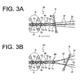
- FIG. 3A shows weft and warp yarns in the first loose picking L1.
- the cloth fell W1 starts to be moved frontward by the terry motion at the angular position ⁇ 3 and reaches the front position at the angular position ⁇ 4 after finishing the weft insertion.
- a weft yarn Y1 is inserted in the first loose picking L1 and beaten by the reed 5 at the beating position W2.
- FIGS. 3B , 4A, 4B, and 4C show weft and warp yarns in the second loose picking L2.
- the cloth fell W1 is kept at the front position.
- a shed that is formed by the ground warp yarns TG for the first loose picking L1 is kept opened.
- the pile warp yarns TP are crossed at the cross timing K1 and forms a shed.
- a weft yarn Y2 is inserted in the shed formed by the ground warp yarns TG and the pile warp yarns TP.
- FIG. 4A when the second loose picking L2 of the weft yarns Y2 is completed and the reed 5 is swung for beating operation, the ground warp yarns TG start to form a shed at the cross timing K2 that occurs earlier than the cross timing K1 for the pile warp yarns TP.
- FIG. 4B the ground warp yarns TG after passing the cross timing K2 starts to form a shed. Then, the pile warp yarns TP reach the cross timing K1, where the warp shed is closed and the tension of the pile warp yarns TP is decreased to minimum level. However, the weft yarn Y2 is then held stably by the ground warp yarns TG tensioned appropriately and forming a shed.
- the weft yarn Y2 is beaten by the reed 5 while being held securely by the ground warp yarns TG forming a shed after the cross timing before the pile warp yarns TP start to form a shed subsequent to the cross timing. Therefore, the pile warp yarns TP between the weft yarns Y1 and Y2 are held securely by and between the weft yarns Y1 and Y2, so that the failure in pile formation due to the force acting to pull the pile warp yarns TP between the weft yarns Y1 and Y3 on the woven cloth W side backward of the loom may be prevented.
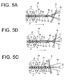
- FIGS. 5A, 5B, and 5C show weft and warp yarns in the fast picking F.
- the cloth fell W1 starts to be moved backward toward the beating position W2 at the angular position ⁇ 1 after beating of the weft yarn Y2 inserted in the second loose picking L2. While the cloth fell W1 is being moved backward, the ground warp yarns TG and the pile warp yarns TP form a shed and the weft yarn Y3 for the fast picking F is inserted in the shed formed by the ground warp yarns TG and the pile warp yarns TP.
- the ground warp yarns TG are crossed at the cross timing K2 and start to form a shed and the cloth fell W1 reaches the beating position W2 at the angular position ⁇ 2.
- the weft yarn Y3 that is held securely by the ground warp yarns TG is beaten to the cloth fell W1.
- piles P1 are formed by the pile warp yarns TP extending between the weft yarns Y3 and Y1 shown in FIG. 5B .
- the first loose picking L1, the second loose picking L2, and the fast picking F described with reference to FIGS. 3A through 5C are repeated to weave the woven cloth W.
- the pile warp yarns TP while the cloth fell W1 is being moved backward toward the beating position W2 and the piles P1 formed after the cloth fell W1 has reached the beating position W2 may be influenced by increasing tension of the pile warp yarns TP occurring during the shedding operation. According to the present embodiment, however, parts at which the piles P1 are fixed to the pile warp yarns TP are held securely by the ground warp yarns TG and the weft yarns Y2 and Y3, so that failure in pile forming which may be caused by the shed movement of the pile warp yarns TP may be prevented.
- the weft yarn Y2 inserted for the second loose picking L2 is held securely by the ground warp yarns TG tensioned at a high level.
- the pile warp yarns TP are held securely between the weft yarn Y1 inserted in the preceding first loose picking L1 and the weft yarn Y2 inserted for the second loose picking L2 and, therefore, the failure in pile formation which may be caused by the increasing tension of the pile warp yarns TP occurring during the shedding operation can be prevented, which enables formation of piles P, P1 with a desired height and contributes to improving the quality of the pile fabric.
- the cross timings K2 in the shed opening diagram for the ground warp yarns TG all occur earlier than the cross timing K1 for the pile warp yarns TP, so that the weft yarns Y2 and Y3 inserted are held securely by the ground warp yarns TG making shedding operation. Therefore, preventive effect against failure in pile formation can be improved.
- the shedding controller C4 controls the shedding motors M4, M5, M6, M7 for the respective heald frames 4A, 4B, 4C, 4D, easily.
- heald frames 4A, 4B, 4C, 4D are driven separately by the respective shedding motors M4, M5, M6, M7 that are controlled by an electronic shedding device, raising and lowering speeds and amount, and cross timings K1, K2 may be set freely.
- the pile warp yarns TP extending between the pile warp beam 17 and the cloth fell W1 will not be loosened and unnecessary stop of the pile fabric loom caused by hanging down of dropper pins (not shown) can be prevented. Additionally, because the secure prevention of the pile formation failure enables to make the tension of the pile warp yarns TP lower than heretofore. As a result, the piles P, P1 are formed properly and the quality of the pile fabric is improved.
- the secure prevention of failure in pile formation can dispense with the setting of pile motion amount that is taken into consideration to prevent failure in pile formation in a loom according to the conventional art, which minimizes the pile motion amount and contributes to stable and high speed operation of the pile fabric loom.
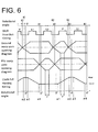
- the second embodiment differs from the first embodiment in that the shed opening diagrams for the ground warp yarns TG and the pile warp yarns TP include a dwell angle ⁇ and that the cross timing K2 of the ground warp yarns TG is made to occur earlier than the cross timing K1 of the pile warp yarns TP by varying the speed in the shed opening and closing operation of the ground warp yarns TG.
- the cross timing K2 is made to occur earlier by increasing the shed closing speed of the ground warp yarns TG after the weft insertion for the second loose picking L2 and the shed opening speed of the ground warp yarns TG after the cross timing K2 is made lower before the weft insertion for the fast picking F.
- the shed closing speed of the ground warp yarns TG is increased when the weft insertion for the fast picking F is being completed thereby to cause the cross timing K2 to occur earlier.
- the shed opening speed of the ground warp yarns TG is lowered for the subsequent first loose picking L1.
- a shed opening diagram may be made in which the cross timing K2 of the ground warp yarns TG occurs earlier by the angle ⁇ than the cross timing K1 of the pile warp yarns TP. Accordingly, the shed of the ground warp yarns TG is closed before the pile warp yarns TP are closed and the ground warp yarns TG are opened before the pile warp yarns TP are opened, with the result that the weft yarns Y2 and Y3 are held securely and failure in pile formation caused by increasing tension of the pile warp yarns TP in the shed opening operation can be prevented.
- the second embodiment has the same effect as the first embodiment.
- a method for shed opening in a pile fabric loom includes heald frames through which ground warp yarns and pile warp yarns are inserted, drive devices driving the respective heald frames, and a shedding controller controlling the drive devices separately so as to open and close a shed of the ground warp yarns and a shed of the pile warp yarns, and forms piles by loose pickings of a plurality of times and fast picking of one time that are performed in conjunction with forward and backward movement of cloth fell.
- the loose picking is followed by the fast picking.
- the method is characterized by setting cross timing to close the shed of the ground warp yarns earlier than cross timing to close the shed of the pile warp yarns at least during a transitional period from the loose picking to the fast picking.
Landscapes
- Engineering & Computer Science (AREA)
- Textile Engineering (AREA)
- Looms (AREA)
Abstract
Description
- The present invention relates to a method for shed opening by ground warp yarns and pile warp yarns in a pile fabric loom.
- Japanese Patent Application Publication No.
2002-173849 - In weaving a three-pick towel fabric, three pickings make one repeat of pile formation. Weft insertion for the first loose picking and the second loose picking, is performed with the cloth fell shifted to a position that is frontward of the weft beating position, or the front position. Weft insertion for the fast picking is performed with the cloth fell located at the weft beating position. In the fast picking, pile warp yarns extending between the weft beating position and the front position are pushed at one ends thereof, thereby forming piles having a predetermined height.
- In weaving a pile towel fabric by the above pile fabric loom, ground warp yarns and pile warp yarns are moved according to the same shedding pattern in one repeat of pile formation. It is noted, however, that the shedding pattern of the pile warp yarns is made by phase-shifting the shedding pattern of the ground warp yarns by one time of picking. Furthermore, the shedding pattern of the ground warp yarns and the shedding pattern of the pile warp yarns have the same cross timing set at a predetermined angular position of the loom (for example, 320 degrees).
- In the above-described pile fabric loom of the above-cited Publication, in order to form piles securely, the tension of pile warp yarns is set lower during a period of time that includes the timing of beating a weft yarn inserted in the fast picking. During a period of time that includes the cross timing of the pile warp yarns after the fast picking, the tension of pile warp yarns is set higher so as to improve separation of pile warp yarns and to prevent mispicking due to poor shedding.
- According to the weaving method of the above-cited Publication, although the piles formed by the fast picking may be formed properly by lowering the tension of the pile warp yarns, the tension of the pile warp yarns increased by the subsequent movement thereof to form a shed tends to cause piles to be formed improperly. Such failure in pile formation lowers the height of the resulting piles and hence causes irregular pile, with the result that the quality of pile fabric is reduced.
- In order to prevent such trouble, a tension roller for adjusting the tension of the pile warp yarns is disposed on the letting-off side of pile warp yarns. The pile warp yarns pass through the tension roller and extend toward the cloth fell through the eyelets of the dropper, the healds, and the reed, so that the tension force adjusted by the tension roller is not applied immediately to the pile warp yarns at the cloth fell position because of the resistance by the dropper, the healds, and the reed. Thus, the use of the above tension roller is not effective to prevent failure in pile formation.
- The present invention is directed to providing a method that prevents failure in pile formation in a pile fabric loom.
- In accordance with one aspect of the present invention, there is provided a method for shed opening in a pile fabric loom. The pile fabric loom includes a plurality of heald frames through which ground warp yarns and pile warp yarns are inserted, a plurality of drive devices driving the respective heald frames, and a shedding controller controlling the drive devices separately so as to open and close a shed of the ground warp yarns and a shed of the pile warp yarns, and forms piles by loose pickings of a plurality of times and fast picking of one time that are performed in conjunction with forward and backward movement of cloth fell. The loose picking is followed by the fast picking. The method is characterized by setting cross timing to close the shed of the ground warp yarns earlier than cross timing to close the shed of the pile warp yarns at least during a transitional period from the loose picking to the fast picking.
- Other aspects and advantages of the invention will become apparent from the following description, taken in conjunction with the accompanying drawings, illustrating by way of example the principles of the invention.
- The invention together with objects and advantages thereof, may best be understood by reference to the following description of the presently preferred embodiments together with the accompanying drawings in which:
-
FIG. 1 is a schematic view showing a pile fabric loom in which a method according to a first embodiment of the present invention is performed; -
FIG. 2 is a chart showing shed opening diagrams for ground and pile warp yarns in the pile fabric loom ofFIG. 1 ; -
FIGS. 3A and 3B are schematic views showing weft and warp yarns in the first loose picking and the second loose picking in the pile fabric loom ofFIG. 1 , respectively; -
FIGS. 4A, 4B and 4C are schematic views showing weft and warp yarns in the second loose picking in the pile fabric loom ofFIG. 1 , respectively; -
FIGS. 5A, 5B and 5C are schematic views showing weft and warp yarns in the fast picking in the pile fabric loom ofFIG. 1 , respectively; and -
FIG. 6 is a chart showing shed opening diagrams for ground and pile warp yarns in a pile fabric loom in which a method according to a second embodiment of the present invention is performed. - The following will describe a pile fabric loom in which a method for controlling the shed opening of pile warp yarns according to a first embodiment is performed with reference of
FIGS. 1 through 5 . Referring toFIG. 1 , the right and the left ofFIG. 1 correspond to the rear and the front of the pile fabric loom, respectively. The upper and the lower sides ofFIG. 1 correspond to the upper and the lower sides of the pile fabric loom, respectively. InFIG. 1 showing the pile fabric loom in side view, a ground warp beam 1 is driven by a ground warp let-off motor M2 that is electrically connected to a ground warp let-off controller C2. - Ground warp yarns TG that are let-off from the ground warp beam 1 with the rotation of the ground warp let-off motor M2 are moved through an arched
back guide plate 2 and atension roller 3 and inserted through a plurality of heald frames 4A, 4B, 4C, 4D and areed 5. Thereed 5 is driven by a drive device (not shown) to swing between the solid-line position for weft insertion and the phantom line-position for beating a weft yarn. Woven cloth W is moved through an expansion bar 6, asurface roller 7, and guiderollers cloth roller 10. -
Numeral 11 designate aframe 11 of the pile fabric loom that supports theback guide plate 2 and rotatably supports atension pipe 12. Thetension pipe 12 has an urging mechanism (not shown) providing urging force to thetension roller 3. Anupper support arm 13 is fixedly mounted to thetension pipe 12 and supports at the upper end thereof thetension roller 3. Tension variation of the ground warp yarn TG caused by shedding of warp yarns is absorbed by the negative easing motion of thetension roller 3 urged by the urging mechanism of thetension pipe 12. - A
lever 14 is fixed to and extends downward from the urging mechanism of thetension pipe 12. Arod 15 is pivotally connected to the lower end of thelever 14. Aload cell 16 is mounted to therod 15 for detecting the tension of ground warp yarns TG acting on thetension roller 3, and electrically connected to the ground warp let-off controller C2. The ground warp let-off controller C2 controls the speed of the ground warp let-off motor M2 based on the comparison of a predetermined reference tension value and data of warp yarn tension detected by theload cell 16. - A
pile warp beam 17 is disposed above the ground warp beam 1. Thepile warp beam 17 is driven by a pile warp let-off motor M3 that is electrically connected to the pile warp let-off controller C3. The pile warp yarns TP that are let off from thepile warp beam 17 are moved through a turningroller 18, a tensioningmember 19 and a terry motion roller 20 and inserted through the heald frames 4A, 4B, 4C, 4D and thereed 5. - The turning
roller 18 is rotatably supported by ashaft 22 that is fixed to theframe 11 and has aload cell 21. Theload cell 21 detects the tension of the pile warp yarns TP and transmits to the pile warp let-off controller C3 a signal of the detected tension. The turningroller 18 has at the opposite ends thereof that are not in contact with the pile warp yarns TP a pair of elements (not shown) to be detected. - A pair of proximity switches 23 (only one being shown) is disposed in facing relation to the above paired elements to be detected. The paired proximity switches 23 detect the rotation of the turning
roller 18 and transmit detection signals to the pile warp let-off controller C3. The pile warp let-off controller C3 controls the speed of the pile warp let-off motor M3 based on the comparison of a predetermined reference tension value and data of warp yarn tension detected by theload cell 21 and also on the detection signals transmitted from the proximity switches 23. - The tensioning
member 19 is supported by a leaf spring 24 fixed to theframe 11. Tension variation of the pile warp yarns TP caused by the warp yarn shed motion is absorbed by the negative easing motion of the tensioningmember 19 due to the deflection of the leaf spring 24. In order to form piles securely in the pile fabric loom, the tension of the pile warp yarns TP is set lower than that of the ground warp yarns TG. A rockinglever 26 having an upper arm and a lower arm is pivotally supported on ashaft 25, and the terry motion roller 20 is rotatably supported by the upper arm of the rockinglever 26. The lower arm of the rockinglever 26 is pivotally connected to therod 15. - A forked
intermediate lever 27 is rotatably mounted on ashaft 28 at an intermediate position as viewed in the front-and-rear direction of the pile fabric loom. Apile motion mechanism 29 is disposed above theintermediate lever 27. Thepile motion mechanism 29 has therein a drive unit (not shown) including a ball screw mechanism or a cam mechanism that is driven by its own drive motor or a loom drive motor M1. Adrive lever 31 is fixed on adrive shaft 30 and reciprocally pivoted by thepile motion mechanism 29. - The loom drive motor M1 is controlled by the loom controller C1 connected to a
rotary encoder 32 that detects the angular position of the pile fabric loom. The loom controller C1 and the pile warp let-off controller C3 are connected to apatterning controller 33. Data of pile weave pattern is set and stored in thepatterning controller 33. Thepatterning controller 33 transmits signals of the data of the pile weave pattern to the loom controller C1 and the pile warp let-off controller C3 at each predetermined angular position of the pile fabric loom in weft picking cycle. Therefore, the loom controller C1 operates thepile motion mechanism 29 in accordance with the pile weave pattern provided by thepatterning controller 33. - The
drive lever 31 of thepile motion mechanism 29 transmits reciprocal pivotal movement to theintermediate lever 27 through arod 35 connected between thedrive lever 31 and onearm 34 of theintermediate lever 27. Theintermediate lever 27 transmits the rocking motion (or terry motion) to thetension roller 3 and the terry motion roller 20 through therod 15 connected to theother arm 36 of theintermediate lever 27. The expansion bar 6 which guides a woven cloth W on the front side of the pile fabric loom is supported by the upper end of a rockinglever 38 which is pivotally supported on ashaft 37. The lower end of the rockinglever 38 is connected to thearm 36 of theintermediate lever 27 through arod 39. - Thus, the reciprocal rocking motion of the
intermediate lever 27 is transmitted to the rockinglever 38 through therod 39 thereby to swing or rock the rockinglever 38. Theintermediate lever 27 transmits the rocking motion (or terry motion) to the expansion bars 6 in the same direction as thetension roller 3 and the terry motion roller 20. In the loose picking in pile weaving operation, thetension roller 3, the terry motion roller 20 and the expansion bar 6 are moved frontward, or leftward inFIG. 1 , and the cloth fell W1 is shifted forward to the loose picking position that is frontward of the beating position indicated by thereed 5 shown in phantom line inFIG. 1 . In the fast picking in the pile weaving operation and the border weaving operation, thetension roller 3, the terry motion roller 20, and the expansion bar 6 are moved backward and the cloth fell W1 is moved back to the beating position of thereed 5. - The heald frames 4A, 4B, 4C, 4D through which ground warp yarns TG and pile warp yarns TP are inserted are driven by a shedding
motion 40. The sheddingmotion 40 includes a plurality of shedding motors M4, M5, M6, M7 that are connected to the respective heald frames 4A, 4B, 4C, 4D. Each of the shedding motors M4, M5, M6, M7 corresponds to the heald frame drive device. Although, for the sake of the illustration, the pile fabric loom shown inFIG. 1 uses fourheald frames - The speeds of the shedding motors M4, M5, M6, M7 are controlled separately, or independently of one another, so that the respective heald frames 4A, 4B, 4C, 4D perform independent shedding operation.
- The shedding
motion 40 is electrically connected to a shedding controller C4 that is in turn electrically connected to the loom controller C1 for mutual communication. The shedding controller C4 has therein data of shedding patterns for the ground warp yarns TG and the pile warp yarns TP that are based on pile weave pattern set and stored in thepatterning controller 33. The shedding controller C4 generates drive signals to the shedding motors M4, M5, M6, M7 in accordance with the shedding patterns. - The following will describe the shedding patterns of the ground warp yarns TG and the pile warp yarns TP set in the shedding controller C4 while referring to
FIG. 2 . The following description will focus on weaving a three-pick pile fabric, or weaving by two times of loose picking followed by one time of fast picking. According to the present invention, however, three or more times of loose picking may be followed by one time of fast picking. -
FIG.2 shows the timing of weft insertion for the first loose picking L1, the second loose picking L2, and the fast picking F, the shed opening diagrams for the ground warp yarns TG and the pile warp yarns TP, and the timing of the cloth fell W1 movement between the rear position that corresponds to the beating position and the front position that is frontward of the beating position, and these timings and diagrams are shown with the angular positions of the pile fabric loom. - In the timing of the weft insertion, the first loose picking L1, the second loose picking L2, and the fast picking F are performed in this order for each rotation of the pile fabric loom from 0° to 360 degrees, and such weft insertions are performed repeatedly as one repeat.
- Referring to the shed opening diagram for the ground warp yarns TG indicated by solid line and chain double-dashed line, in the period of time between the first loose picking L1 and the second loose picking L2, a shed that corresponds to two consecutive weft insertions is formed by the ground warp yarns TG. In the period of time of the fast picking F, a shed corresponding to one time of weft insertion is formed by the ground warp yarns TG. The shed opening diagram for the pile warp yarns TP is made by phase shifting the shed opening for the ground warp yarns TG by 360 degrees corresponding to one complete rotation of the pile fabric loom. In the period of time between the fast picking F and the first loose picking L1, a shed that corresponds to two consecutive weft insertions is formed by the pile warp yarns TP. For the second loose picking L2, the pile warp yarns TP forms a shed corresponding to one time of the weft insertion.
- As to the timing of the cloth fell W1 movement, the cloth fell W1 starts to move from the front position toward the rear beating position W2 (
FIGS. 3A, 3B ) when the loom is at the angular position α1 after the beating of a weft yarn for the second loose picking L2 at angular position 0°. At the beginning of the cloth fell W1 movement toward the rear position, the ground warp yarns TG and the pile warp yarns TP have already started forming a shed. At the angular position α2 after completion of the fast picking F, the cloth fell W1 reaches the beating position W2 at the rotational angle α2 and beating a weft yarn is performed at angular position 0°. - After the beating of a weft yarn of the fast picking F, the cloth fell W1 starts to move frontward from the beating position W2 at the rotational angle α3 and reaches the front position at the angular position α4 that is before the beating of a weft yarn of the first loose picking L1 at angular position 0°. The cloth fell W1 starts to move frontward and backward between the front position and the beating position W2 at the timings of the angular positions α1, α2, α3, α4 in conjunction with the first loose picking L1, the second loose picking L2, and the fast picking F.
- In the pile weaving operation in the pile fabric loom according to the conventional art, the shed opening diagram for the ground warp yarns TG is shown by chain double-dashed line in
FIG. 2 . That is, the phase of the shed opening diagram of the ground warp yarns TG is shifted by 360 degrees corresponding to one rotation of the pile fabric loom with regard to the shed opening diagram of the pile warp yarns TP. Specifically, the shed opening diagram for the ground warp yarns TG is made by phase shifting the shed opening diagram for pile warp yarns TP by 360 degrees corresponding to one complete rotation of the pile fabric loom. Thus, the cross timing K1 of the ground warp yarns TG is set the same as that of the pile warp yarns TP. - According to the present embodiment, the phase of the shed opening diagram for the ground warp yarns TG, which is shown by solid line in
FIG. 2 , is advanced by the angle β with respect to the shed opening diagram in the pile fabric loom according to the conventional art. Therefore, the cross timing K2 of the ground warp yarns TG occurs earlier than the cross timing K1 of the pile warp yarns TP. - Advancing the cross timing K2 by the angle β with respect to the cross timing K1, the ground warp yarns TG has already started forming a shed when the shed of the pile warp yarns TP is closed at the cross timing K1. The ground warp yarns TG and the pile warp yarns TP are moved for shed opening and closing during a transitional period from the second loose picking L2 to the fast picking F, during which the cloth fell W1 starts to move backward toward the beating position W2.
- The following will describe the operation of the above-described pile fabric weaving loom with reference to
FIGS. 2 through 5 . The heald frames 4A, 4B, 4C, 4D through which ground warp yarns TG and pile warp yarns TP are inserted are driven by the shedding motors M4, M5, M6, M8 that are controlled by the shedding controller C4. The heald frames 4A, 4B, 4C, 4D are moved so as to open and close a shed of the ground warp yarns TG and the pile warp yarns TP according to the shed opening diagram shown inFIG. 2 .FIG. 3A shows weft and warp yarns in the first loose picking L1. In the first loose picking L1, the cloth fell W1 starts to be moved frontward by the terry motion at the angular position α3 and reaches the front position at the angular position α4 after finishing the weft insertion. A weft yarn Y1 is inserted in the first loose picking L1 and beaten by thereed 5 at the beating position W2. -
FIGS. 3B ,4A, 4B, and 4C show weft and warp yarns in the second loose picking L2. The cloth fell W1 is kept at the front position. InFIG. 3B , a shed that is formed by the ground warp yarns TG for the first loose picking L1 is kept opened. After completion of the first loose picking L1, the pile warp yarns TP are crossed at the cross timing K1 and forms a shed. Then, a weft yarn Y2 is inserted in the shed formed by the ground warp yarns TG and the pile warp yarns TP. - In
FIG. 4A , when the second loose picking L2 of the weft yarns Y2 is completed and thereed 5 is swung for beating operation, the ground warp yarns TG start to form a shed at the cross timing K2 that occurs earlier than the cross timing K1 for the pile warp yarns TP. InFIG. 4B , the ground warp yarns TG after passing the cross timing K2 starts to form a shed. Then, the pile warp yarns TP reach the cross timing K1, where the warp shed is closed and the tension of the pile warp yarns TP is decreased to minimum level. However, the weft yarn Y2 is then held stably by the ground warp yarns TG tensioned appropriately and forming a shed. - In
FIG. 4C , while a shed is being formed by the ground warp yarns TG, the pile warp yarns TP pass the cross timing K1 and start to form a shed, and the weft yarn Y2 is beaten by thereed 5 at the beating position W2 corresponding to angular position 0° of the loom. As pile warp yarns TP start to form a shed, the tension of the pile warp yarns TP increases. Such an increasing tension of the pile warp yarns TP acts on the pile warp yarns TP extending between the weft yarns Y1 and Y2 in the direction that pulls the pile warp yarns TP backward in the pile fabric loom. Therefore, the increasing tension of the pile warp yarns TP may cause a failure in pile formation. - In the present embodiment, however, the weft yarn Y2 is beaten by the
reed 5 while being held securely by the ground warp yarns TG forming a shed after the cross timing before the pile warp yarns TP start to form a shed subsequent to the cross timing. Therefore, the pile warp yarns TP between the weft yarns Y1 and Y2 are held securely by and between the weft yarns Y1 and Y2, so that the failure in pile formation due to the force acting to pull the pile warp yarns TP between the weft yarns Y1 and Y3 on the woven cloth W side backward of the loom may be prevented. -
FIGS. 5A, 5B, and 5C show weft and warp yarns in the fast picking F. InFIG. 5A , the cloth fell W1 starts to be moved backward toward the beating position W2 at the angular position α1 after beating of the weft yarn Y2 inserted in the second loose picking L2. While the cloth fell W1 is being moved backward, the ground warp yarns TG and the pile warp yarns TP form a shed and the weft yarn Y3 for the fast picking F is inserted in the shed formed by the ground warp yarns TG and the pile warp yarns TP. - In
FIG. 5B , the weft insertion of the weft yarn Y3 for the fast picking F is completed and the shed of the ground warp yarns TG is closed at the cross timing K2. Then, the cloth fell W1 is being moved backward toward the beating position W2. When the shed of the ground warp yarns TG is closed, the weft yarn Y3 is securely held by the ground warp yarns TG the tension of which is set high. The shed of the pile warp yarns TP remains open in the subsequent first loose picking L1. - In
FIG. 5C , the ground warp yarns TG are crossed at the cross timing K2 and start to form a shed and the cloth fell W1 reaches the beating position W2 at the angular position α2. At the subsequent angular position 0° of the loom, the weft yarn Y3 that is held securely by the ground warp yarns TG is beaten to the cloth fell W1. As the result of the beating of the weft yarn Y3, piles P1 are formed by the pile warp yarns TP extending between the weft yarns Y3 and Y1 shown inFIG. 5B . The first loose picking L1, the second loose picking L2, and the fast picking F described with reference toFIGS. 3A through 5C are repeated to weave the woven cloth W. - In
FIGS. 5A, 5B, and 5C , the pile warp yarns TP while the cloth fell W1 is being moved backward toward the beating position W2 and the piles P1 formed after the cloth fell W1 has reached the beating position W2 may be influenced by increasing tension of the pile warp yarns TP occurring during the shedding operation. According to the present embodiment, however, parts at which the piles P1 are fixed to the pile warp yarns TP are held securely by the ground warp yarns TG and the weft yarns Y2 and Y3, so that failure in pile forming which may be caused by the shed movement of the pile warp yarns TP may be prevented. - In the first embodiment, in which the cross timing K2 of the ground warp yarns TG occurs earlier than the cross timing K1 of the pile warp yarns TP, the weft yarn Y2 inserted for the second loose picking L2 is held securely by the ground warp yarns TG tensioned at a high level. Thus, the pile warp yarns TP are held securely between the weft yarn Y1 inserted in the preceding first loose picking L1 and the weft yarn Y2 inserted for the second loose picking L2 and, therefore, the failure in pile formation which may be caused by the increasing tension of the pile warp yarns TP occurring during the shedding operation can be prevented, which enables formation of piles P, P1 with a desired height and contributes to improving the quality of the pile fabric.
- The cross timings K2 in the shed opening diagram for the ground warp yarns TG all occur earlier than the cross timing K1 for the pile warp yarns TP, so that the weft yarns Y2 and Y3 inserted are held securely by the ground warp yarns TG making shedding operation. Therefore, preventive effect against failure in pile formation can be improved.
- Phase shifting the shed opening diagram for the ground warp yarns TG from that of the pile warp yarns TP, the cross timing K2 of the ground warp yarns TG takes place earlier than the cross timing K1 of the pile warp yarns TP. Thus, the shed opening diagram of the ground warp yarns TG in which the cross timing K2 of the ground warp yarns TG is earlier than the cross timing K1 of the pile warp yarns TP may be made easily. Additionally, the shedding controller C4 controls the shedding motors M4, M5, M6, M7 for the respective heald frames 4A, 4B, 4C, 4D, easily.
- Because the heald frames 4A, 4B, 4C, 4D are driven separately by the respective shedding motors M4, M5, M6, M7 that are controlled by an electronic shedding device, raising and lowering speeds and amount, and cross timings K1, K2 may be set freely.
- In the present embodiment according to which failure in pile formation is prevented securely, the pile warp yarns TP extending between the
pile warp beam 17 and the cloth fell W1 will not be loosened and unnecessary stop of the pile fabric loom caused by hanging down of dropper pins (not shown) can be prevented. Additionally, because the secure prevention of the pile formation failure enables to make the tension of the pile warp yarns TP lower than heretofore. As a result, the piles P, P1 are formed properly and the quality of the pile fabric is improved. - The secure prevention of failure in pile formation can dispense with the setting of pile motion amount that is taken into consideration to prevent failure in pile formation in a loom according to the conventional art, which minimizes the pile motion amount and contributes to stable and high speed operation of the pile fabric loom.
- The following will describe a second embodiment according to the present invention with reference to
FIG. 6 . The same reference numerals will be used to denote those components or elements which correspond to the counterparts of the first embodiment and the description thereof will not be reiterated. The second embodiment differs from the first embodiment in that the shed opening diagrams for the ground warp yarns TG and the pile warp yarns TP include a dwell angle γ and that the cross timing K2 of the ground warp yarns TG is made to occur earlier than the cross timing K1 of the pile warp yarns TP by varying the speed in the shed opening and closing operation of the ground warp yarns TG. - In the shed opening diagram for the ground warp yarns TG, the cross timing K2 is made to occur earlier by increasing the shed closing speed of the ground warp yarns TG after the weft insertion for the second loose picking L2 and the shed opening speed of the ground warp yarns TG after the cross timing K2 is made lower before the weft insertion for the fast picking F. During the transition from the fast picking F to the first loose picking L1, the shed closing speed of the ground warp yarns TG is increased when the weft insertion for the fast picking F is being completed thereby to cause the cross timing K2 to occur earlier. After the cross timing K2 of the ground warp yarns TG, the shed opening speed of the ground warp yarns TG is lowered for the subsequent first loose picking L1.
- According to the second embodiment, a shed opening diagram may be made in which the cross timing K2 of the ground warp yarns TG occurs earlier by the angle β than the cross timing K1 of the pile warp yarns TP. Accordingly, the shed of the ground warp yarns TG is closed before the pile warp yarns TP are closed and the ground warp yarns TG are opened before the pile warp yarns TP are opened, with the result that the weft yarns Y2 and Y3 are held securely and failure in pile formation caused by increasing tension of the pile warp yarns TP in the shed opening operation can be prevented. Thus, the second embodiment has the same effect as the first embodiment.
- The present invention is not limited to the embodiments described above, but it may be modified into various alternative embodiments as exemplified below.
- (1) In the first and the second embodiments, the cross timings K2 of the shed opening diagram for the ground warp yarns TG occur earlier than the cross timing K1 of the shed opening diagram for the pile warp yarns TP. According to the present invention, however, it may be so configured that the cross timing K2 of the ground warp yarns TG takes place earlier than the cross timing K1 of the pile warp yarns TP only during the transition from the second loose picking L2 to the fast picking F. The other cross timings K2 of the ground warp yarns TG may be the same as the cross timings K1 of the pile warp yarns TP.
- (2) In the first and the second embodiments, an electronic dobby having electromagnetic devices such as solenoids may be used to drive the respective heald frames 4A, 4B, 4C, 4D.
- A method is provided for shed opening in a pile fabric loom. The pile fabric loom includes heald frames through which ground warp yarns and pile warp yarns are inserted, drive devices driving the respective heald frames, and a shedding controller controlling the drive devices separately so as to open and close a shed of the ground warp yarns and a shed of the pile warp yarns, and forms piles by loose pickings of a plurality of times and fast picking of one time that are performed in conjunction with forward and backward movement of cloth fell. The loose picking is followed by the fast picking. The method is characterized by setting cross timing to close the shed of the ground warp yarns earlier than cross timing to close the shed of the pile warp yarns at least during a transitional period from the loose picking to the fast picking.
Claims (4)
- A method for shed opening in a pile fabric loom, wherein the pile fabric loom includes a plurality of heald frames (4A, 4B, 4C, 4D) through which ground warp yarns (TG) and pile warp yarns (TP) are inserted, a plurality of drive devices driving the respective heald frames (4A, 4B, 4C, 4D), and a shedding controller (C4) controlling the drive devices separately so as to open and close a shed of the ground warp yarns (TG) and a shed of the pile warp yarns (TP), and forms piles by loose picking (L1, L2) of a plurality of times and fast picking (F) of one time that are performed in conjunction with forward and backward movement of cloth fell, the loose picking (L1, L2) being followed by the fast picking (F),
characterized by
setting cross timing (K2) to close the shed of the ground warp yarns (TG) earlier than cross timing (K1) to close the shed of the pile warp yarns (TP) at least during a transitional period from the loose picking (L2) to the fast picking (F). - The method for the shed opening in the pile fabric loom according to claim 1, characterized by setting the cross timing (K2) to close the shed of the ground warp yarns (TG) constantly earlier than the cross timing (K1) to close the shed of the pile warp yarns (TP) during a period other than the transitional period.
- The method for the shed opening in the pile fabric loom according to claim 2, characterized by shifting a phase of a predetermined shedding movement of the ground warp yarns (TG) to set the cross timing (K2) to close the shed of the ground warp yarns (TG) earlier than the cross timing (K1) to close the shed of the pile warp yarns (TP).
- The method for the shed opening in the pile fabric loom according to any one of claims 1 through 3, characterized in that the drive devices include respective shedding motors (M4, M5, M6, M7) that are connected to the respective heald frames (4A, 4B, 4C, 4D).
Applications Claiming Priority (1)
| Application Number | Priority Date | Filing Date | Title |
|---|---|---|---|
| JP2015132901A JP6281530B2 (en) | 2015-07-01 | 2015-07-01 | Method for opening warp in pile loom |
Publications (2)
| Publication Number | Publication Date |
|---|---|
| EP3112511A1 true EP3112511A1 (en) | 2017-01-04 |
| EP3112511B1 EP3112511B1 (en) | 2018-05-02 |
Family
ID=56117583
Family Applications (1)
| Application Number | Title | Priority Date | Filing Date |
|---|---|---|---|
| EP16173760.6A Active EP3112511B1 (en) | 2015-07-01 | 2016-06-09 | Method for shed opening in pile fabric loom |
Country Status (3)
| Country | Link |
|---|---|
| EP (1) | EP3112511B1 (en) |
| JP (1) | JP6281530B2 (en) |
| CN (1) | CN106319736B (en) |
Families Citing this family (1)
| Publication number | Priority date | Publication date | Assignee | Title |
|---|---|---|---|---|
| CN109680389B (en) * | 2019-01-21 | 2024-06-04 | 江苏友诚数控科技有限公司 | Reinforcing rib fabric loom in flip cover of automobile safety airbag |
Citations (1)
| Publication number | Priority date | Publication date | Assignee | Title |
|---|---|---|---|---|
| JP2002173849A (en) | 2000-12-11 | 2002-06-21 | Tsudakoma Corp | Pile warp control method and pile warp control device |
Family Cites Families (9)
| Publication number | Priority date | Publication date | Assignee | Title |
|---|---|---|---|---|
| US3409051A (en) * | 1966-05-24 | 1968-11-05 | Bigelow Sanford Inc | Pile fabric loom |
| GR58268B (en) * | 1974-10-29 | 1977-09-15 | Reg Patax Trust | Method manufacturing one band at least,of crepe.machinery weaving bands without shuttle for performance of this method and band of grepe protected during this invention |
| GB1595727A (en) * | 1978-05-18 | 1981-08-19 | Crabtree & Son Ltd D | Aximinster carpet and method of and apparatus for weaving the same |
| CH641218A5 (en) * | 1979-10-19 | 1984-02-15 | Staeubli Ag | UPPER CABLE BETWEEN A DUMPING MACHINE AND THE SHAFTS OF A WEAVING MACHINE. |
| SU1291625A1 (en) * | 1985-04-19 | 1987-02-23 | Климовское Специальное Конструкторское Бюро Ткацкого Оборудования | Double-web pile fabric loom |
| US5518037A (en) * | 1993-09-13 | 1996-05-21 | Kabushiki Kaisha Toyoda Jidoshokki Seisakusho | Cloth fell displacement in a terry loom |
| JPH10298849A (en) * | 1997-04-25 | 1998-11-10 | Toyota Autom Loom Works Ltd | Determination of standard position in loom and device therefor |
| JP2004169227A (en) * | 2002-11-21 | 2004-06-17 | Tsudakoma Corp | Pile loom control method |
| EP2251467B1 (en) * | 2009-05-13 | 2013-08-07 | SCHÖNHERR Textilmaschinenbau GmbH | Method for simultaneously weaving two fabrics, fabric adapted to be woven with such a method and loom usable with such a method |
-
2015
- 2015-07-01 JP JP2015132901A patent/JP6281530B2/en active Active
-
2016
- 2016-06-09 EP EP16173760.6A patent/EP3112511B1/en active Active
- 2016-06-28 CN CN201610490775.0A patent/CN106319736B/en active Active
Patent Citations (1)
| Publication number | Priority date | Publication date | Assignee | Title |
|---|---|---|---|---|
| JP2002173849A (en) | 2000-12-11 | 2002-06-21 | Tsudakoma Corp | Pile warp control method and pile warp control device |
Also Published As
| Publication number | Publication date |
|---|---|
| JP2017014665A (en) | 2017-01-19 |
| EP3112511B1 (en) | 2018-05-02 |
| CN106319736B (en) | 2018-02-27 |
| CN106319736A (en) | 2017-01-11 |
| JP6281530B2 (en) | 2018-02-21 |
Similar Documents
| Publication | Publication Date | Title |
|---|---|---|
| US5014756A (en) | Pile warp tension control in a loom | |
| JPH0718071B2 (en) | Soccer loom | |
| CN101748552B (en) | Pile fabric loom having pile warp tension adjuster | |
| EP3106554B1 (en) | Method for controlling shed opening of pile warp yarns in pile fabric loom | |
| JP2004011065A (en) | Pile loom | |
| CN106555268B (en) | Multilayer cloth multi-shed rapier loom | |
| US3889719A (en) | Weaving machine for producing terry cloth | |
| EP3112511B1 (en) | Method for shed opening in pile fabric loom | |
| US7438092B2 (en) | Power loom, particularly an air jet power loom, for the production of a leno fabric with integral patterning | |
| US3339589A (en) | Sley motion for terry loom | |
| CN106400283B (en) | Device for adjusting the tension of pile warp yarns in terry looms | |
| EP1920094B1 (en) | Method and device for forming a leno fabric on a weaving machine | |
| US4006759A (en) | Locked toggle beater drive for triaxial weaving machine | |
| DE69814982T2 (en) | Weft insertion control device with a weft identification system for terry weaving machines | |
| JPH11172552A (en) | Warp tension correcting method for cloth-moving pile loom | |
| CN101387028A (en) | Method for Controlling Heald Frame Movement of Double Carpet Weaving Machine | |
| JP3466547B2 (en) | Warp tension control method | |
| CN101194058B (en) | Terry loom | |
| JP2006077340A (en) | Pile forming method and apparatus in cloth moving pile loom | |
| JP4651082B2 (en) | How to adjust pile warp tension | |
| JPH10130988A (en) | Control of opening in weaving machine and apparatus therefor | |
| JP2002173849A (en) | Pile warp control method and pile warp control device | |
| EP1826302A2 (en) | Shedding device in loom and gaiting method in loom equipped with the shedding device | |
| RU2404303C2 (en) | Method for control of warp threads tension and device for its realisation | |
| JPH10317256A (en) | Warp tension control for pile in pile loom and equipment therefor |
Legal Events
| Date | Code | Title | Description |
|---|---|---|---|
| PUAI | Public reference made under article 153(3) epc to a published international application that has entered the european phase |
Free format text: ORIGINAL CODE: 0009012 |
|
| 17P | Request for examination filed |
Effective date: 20160609 |
|
| AK | Designated contracting states |
Kind code of ref document: A1 Designated state(s): AL AT BE BG CH CY CZ DE DK EE ES FI FR GB GR HR HU IE IS IT LI LT LU LV MC MK MT NL NO PL PT RO RS SE SI SK SM TR |
|
| AX | Request for extension of the european patent |
Extension state: BA ME |
|
| GRAP | Despatch of communication of intention to grant a patent |
Free format text: ORIGINAL CODE: EPIDOSNIGR1 |
|
| RIC1 | Information provided on ipc code assigned before grant |
Ipc: D03C 1/14 20060101ALI20171017BHEP Ipc: D03D 39/22 20060101AFI20171017BHEP |
|
| INTG | Intention to grant announced |
Effective date: 20171109 |
|
| GRAS | Grant fee paid |
Free format text: ORIGINAL CODE: EPIDOSNIGR3 |
|
| GRAA | (expected) grant |
Free format text: ORIGINAL CODE: 0009210 |
|
| AK | Designated contracting states |
Kind code of ref document: B1 Designated state(s): AL AT BE BG CH CY CZ DE DK EE ES FI FR GB GR HR HU IE IS IT LI LT LU LV MC MK MT NL NO PL PT RO RS SE SI SK SM TR |
|
| REG | Reference to a national code |
Ref country code: GB Ref legal event code: FG4D |
|
| REG | Reference to a national code |
Ref country code: CH Ref legal event code: EP Ref country code: AT Ref legal event code: REF Ref document number: 995356 Country of ref document: AT Kind code of ref document: T Effective date: 20180515 |
|
| REG | Reference to a national code |
Ref country code: DE Ref legal event code: R096 Ref document number: 602016002709 Country of ref document: DE Ref country code: IE Ref legal event code: FG4D |
|
| REG | Reference to a national code |
Ref country code: NL Ref legal event code: MP Effective date: 20180502 |
|
| REG | Reference to a national code |
Ref country code: LT Ref legal event code: MG4D |
|
| PG25 | Lapsed in a contracting state [announced via postgrant information from national office to epo] |
Ref country code: BG Free format text: LAPSE BECAUSE OF FAILURE TO SUBMIT A TRANSLATION OF THE DESCRIPTION OR TO PAY THE FEE WITHIN THE PRESCRIBED TIME-LIMIT Effective date: 20180802 Ref country code: NO Free format text: LAPSE BECAUSE OF FAILURE TO SUBMIT A TRANSLATION OF THE DESCRIPTION OR TO PAY THE FEE WITHIN THE PRESCRIBED TIME-LIMIT Effective date: 20180802 Ref country code: SE Free format text: LAPSE BECAUSE OF FAILURE TO SUBMIT A TRANSLATION OF THE DESCRIPTION OR TO PAY THE FEE WITHIN THE PRESCRIBED TIME-LIMIT Effective date: 20180502 Ref country code: FI Free format text: LAPSE BECAUSE OF FAILURE TO SUBMIT A TRANSLATION OF THE DESCRIPTION OR TO PAY THE FEE WITHIN THE PRESCRIBED TIME-LIMIT Effective date: 20180502 Ref country code: LT Free format text: LAPSE BECAUSE OF FAILURE TO SUBMIT A TRANSLATION OF THE DESCRIPTION OR TO PAY THE FEE WITHIN THE PRESCRIBED TIME-LIMIT Effective date: 20180502 Ref country code: ES Free format text: LAPSE BECAUSE OF FAILURE TO SUBMIT A TRANSLATION OF THE DESCRIPTION OR TO PAY THE FEE WITHIN THE PRESCRIBED TIME-LIMIT Effective date: 20180502 |
|
| PG25 | Lapsed in a contracting state [announced via postgrant information from national office to epo] |
Ref country code: HR Free format text: LAPSE BECAUSE OF FAILURE TO SUBMIT A TRANSLATION OF THE DESCRIPTION OR TO PAY THE FEE WITHIN THE PRESCRIBED TIME-LIMIT Effective date: 20180502 Ref country code: GR Free format text: LAPSE BECAUSE OF FAILURE TO SUBMIT A TRANSLATION OF THE DESCRIPTION OR TO PAY THE FEE WITHIN THE PRESCRIBED TIME-LIMIT Effective date: 20180803 Ref country code: NL Free format text: LAPSE BECAUSE OF FAILURE TO SUBMIT A TRANSLATION OF THE DESCRIPTION OR TO PAY THE FEE WITHIN THE PRESCRIBED TIME-LIMIT Effective date: 20180502 Ref country code: LV Free format text: LAPSE BECAUSE OF FAILURE TO SUBMIT A TRANSLATION OF THE DESCRIPTION OR TO PAY THE FEE WITHIN THE PRESCRIBED TIME-LIMIT Effective date: 20180502 Ref country code: RS Free format text: LAPSE BECAUSE OF FAILURE TO SUBMIT A TRANSLATION OF THE DESCRIPTION OR TO PAY THE FEE WITHIN THE PRESCRIBED TIME-LIMIT Effective date: 20180502 |
|
| REG | Reference to a national code |
Ref country code: AT Ref legal event code: MK05 Ref document number: 995356 Country of ref document: AT Kind code of ref document: T Effective date: 20180502 |
|
| PG25 | Lapsed in a contracting state [announced via postgrant information from national office to epo] |
Ref country code: SK Free format text: LAPSE BECAUSE OF FAILURE TO SUBMIT A TRANSLATION OF THE DESCRIPTION OR TO PAY THE FEE WITHIN THE PRESCRIBED TIME-LIMIT Effective date: 20180502 Ref country code: RO Free format text: LAPSE BECAUSE OF FAILURE TO SUBMIT A TRANSLATION OF THE DESCRIPTION OR TO PAY THE FEE WITHIN THE PRESCRIBED TIME-LIMIT Effective date: 20180502 Ref country code: EE Free format text: LAPSE BECAUSE OF FAILURE TO SUBMIT A TRANSLATION OF THE DESCRIPTION OR TO PAY THE FEE WITHIN THE PRESCRIBED TIME-LIMIT Effective date: 20180502 Ref country code: CZ Free format text: LAPSE BECAUSE OF FAILURE TO SUBMIT A TRANSLATION OF THE DESCRIPTION OR TO PAY THE FEE WITHIN THE PRESCRIBED TIME-LIMIT Effective date: 20180502 Ref country code: AT Free format text: LAPSE BECAUSE OF FAILURE TO SUBMIT A TRANSLATION OF THE DESCRIPTION OR TO PAY THE FEE WITHIN THE PRESCRIBED TIME-LIMIT Effective date: 20180502 Ref country code: DK Free format text: LAPSE BECAUSE OF FAILURE TO SUBMIT A TRANSLATION OF THE DESCRIPTION OR TO PAY THE FEE WITHIN THE PRESCRIBED TIME-LIMIT Effective date: 20180502 Ref country code: PL Free format text: LAPSE BECAUSE OF FAILURE TO SUBMIT A TRANSLATION OF THE DESCRIPTION OR TO PAY THE FEE WITHIN THE PRESCRIBED TIME-LIMIT Effective date: 20180502 |
|
| REG | Reference to a national code |
Ref country code: DE Ref legal event code: R097 Ref document number: 602016002709 Country of ref document: DE |
|
| PG25 | Lapsed in a contracting state [announced via postgrant information from national office to epo] |
Ref country code: SM Free format text: LAPSE BECAUSE OF FAILURE TO SUBMIT A TRANSLATION OF THE DESCRIPTION OR TO PAY THE FEE WITHIN THE PRESCRIBED TIME-LIMIT Effective date: 20180502 |
|
| REG | Reference to a national code |
Ref country code: BE Ref legal event code: MM Effective date: 20180630 |
|
| PLBE | No opposition filed within time limit |
Free format text: ORIGINAL CODE: 0009261 |
|
| STAA | Information on the status of an ep patent application or granted ep patent |
Free format text: STATUS: NO OPPOSITION FILED WITHIN TIME LIMIT |
|
| REG | Reference to a national code |
Ref country code: IE Ref legal event code: MM4A |
|
| PG25 | Lapsed in a contracting state [announced via postgrant information from national office to epo] |
Ref country code: MC Free format text: LAPSE BECAUSE OF FAILURE TO SUBMIT A TRANSLATION OF THE DESCRIPTION OR TO PAY THE FEE WITHIN THE PRESCRIBED TIME-LIMIT Effective date: 20180502 Ref country code: LU Free format text: LAPSE BECAUSE OF NON-PAYMENT OF DUE FEES Effective date: 20180609 |
|
| 26N | No opposition filed |
Effective date: 20190205 |
|
| PG25 | Lapsed in a contracting state [announced via postgrant information from national office to epo] |
Ref country code: FR Free format text: LAPSE BECAUSE OF NON-PAYMENT OF DUE FEES Effective date: 20180702 Ref country code: IE Free format text: LAPSE BECAUSE OF NON-PAYMENT OF DUE FEES Effective date: 20180609 |
|
| PG25 | Lapsed in a contracting state [announced via postgrant information from national office to epo] |
Ref country code: BE Free format text: LAPSE BECAUSE OF NON-PAYMENT OF DUE FEES Effective date: 20180630 Ref country code: SI Free format text: LAPSE BECAUSE OF FAILURE TO SUBMIT A TRANSLATION OF THE DESCRIPTION OR TO PAY THE FEE WITHIN THE PRESCRIBED TIME-LIMIT Effective date: 20180502 |
|
| PG25 | Lapsed in a contracting state [announced via postgrant information from national office to epo] |
Ref country code: AL Free format text: LAPSE BECAUSE OF FAILURE TO SUBMIT A TRANSLATION OF THE DESCRIPTION OR TO PAY THE FEE WITHIN THE PRESCRIBED TIME-LIMIT Effective date: 20180502 |
|
| PG25 | Lapsed in a contracting state [announced via postgrant information from national office to epo] |
Ref country code: MT Free format text: LAPSE BECAUSE OF NON-PAYMENT OF DUE FEES Effective date: 20180609 |
|
| REG | Reference to a national code |
Ref country code: CH Ref legal event code: PL |
|
| PG25 | Lapsed in a contracting state [announced via postgrant information from national office to epo] |
Ref country code: TR Free format text: LAPSE BECAUSE OF FAILURE TO SUBMIT A TRANSLATION OF THE DESCRIPTION OR TO PAY THE FEE WITHIN THE PRESCRIBED TIME-LIMIT Effective date: 20180502 |
|
| PG25 | Lapsed in a contracting state [announced via postgrant information from national office to epo] |
Ref country code: LI Free format text: LAPSE BECAUSE OF NON-PAYMENT OF DUE FEES Effective date: 20190630 Ref country code: CH Free format text: LAPSE BECAUSE OF NON-PAYMENT OF DUE FEES Effective date: 20190630 Ref country code: PT Free format text: LAPSE BECAUSE OF FAILURE TO SUBMIT A TRANSLATION OF THE DESCRIPTION OR TO PAY THE FEE WITHIN THE PRESCRIBED TIME-LIMIT Effective date: 20180502 |
|
| PG25 | Lapsed in a contracting state [announced via postgrant information from national office to epo] |
Ref country code: MK Free format text: LAPSE BECAUSE OF NON-PAYMENT OF DUE FEES Effective date: 20180502 Ref country code: HU Free format text: LAPSE BECAUSE OF FAILURE TO SUBMIT A TRANSLATION OF THE DESCRIPTION OR TO PAY THE FEE WITHIN THE PRESCRIBED TIME-LIMIT; INVALID AB INITIO Effective date: 20160609 Ref country code: CY Free format text: LAPSE BECAUSE OF FAILURE TO SUBMIT A TRANSLATION OF THE DESCRIPTION OR TO PAY THE FEE WITHIN THE PRESCRIBED TIME-LIMIT Effective date: 20180502 |
|
| PG25 | Lapsed in a contracting state [announced via postgrant information from national office to epo] |
Ref country code: IS Free format text: LAPSE BECAUSE OF FAILURE TO SUBMIT A TRANSLATION OF THE DESCRIPTION OR TO PAY THE FEE WITHIN THE PRESCRIBED TIME-LIMIT Effective date: 20180902 |
|
| GBPC | Gb: european patent ceased through non-payment of renewal fee |
Effective date: 20200609 |
|
| PG25 | Lapsed in a contracting state [announced via postgrant information from national office to epo] |
Ref country code: GB Free format text: LAPSE BECAUSE OF NON-PAYMENT OF DUE FEES Effective date: 20200609 |
|
| P01 | Opt-out of the competence of the unified patent court (upc) registered |
Effective date: 20230519 |
|
| PGFP | Annual fee paid to national office [announced via postgrant information from national office to epo] |
Ref country code: DE Payment date: 20250429 Year of fee payment: 10 |
|
| PGFP | Annual fee paid to national office [announced via postgrant information from national office to epo] |
Ref country code: IT Payment date: 20250522 Year of fee payment: 10 |