EP3112255A1 - Stowage carousel and method of storing cargo for use with an aircraft - Google Patents
Stowage carousel and method of storing cargo for use with an aircraft Download PDFInfo
- Publication number
- EP3112255A1 EP3112255A1 EP16177326.2A EP16177326A EP3112255A1 EP 3112255 A1 EP3112255 A1 EP 3112255A1 EP 16177326 A EP16177326 A EP 16177326A EP 3112255 A1 EP3112255 A1 EP 3112255A1
- Authority
- EP
- European Patent Office
- Prior art keywords
- stowage
- carousel
- aircraft
- revolving conveyor
- fuselage
- Prior art date
- Legal status (The legal status is an assumption and is not a legal conclusion. Google has not performed a legal analysis and makes no representation as to the accuracy of the status listed.)
- Granted
Links
Images




Classifications
-
- B—PERFORMING OPERATIONS; TRANSPORTING
- B64—AIRCRAFT; AVIATION; COSMONAUTICS
- B64D—EQUIPMENT FOR FITTING IN OR TO AIRCRAFT; FLIGHT SUITS; PARACHUTES; ARRANGEMENT OR MOUNTING OF POWER PLANTS OR PROPULSION TRANSMISSIONS IN AIRCRAFT
- B64D11/00—Passenger or crew accommodation; Flight-deck installations not otherwise provided for
- B64D11/003—Stowage devices for passengers' personal luggage
-
- B—PERFORMING OPERATIONS; TRANSPORTING
- B64—AIRCRAFT; AVIATION; COSMONAUTICS
- B64C—AEROPLANES; HELICOPTERS
- B64C1/00—Fuselages; Constructional features common to fuselages, wings, stabilising surfaces or the like
- B64C1/22—Other structures integral with fuselages to facilitate loading, e.g. cargo bays, cranes
-
- B—PERFORMING OPERATIONS; TRANSPORTING
- B64—AIRCRAFT; AVIATION; COSMONAUTICS
- B64D—EQUIPMENT FOR FITTING IN OR TO AIRCRAFT; FLIGHT SUITS; PARACHUTES; ARRANGEMENT OR MOUNTING OF POWER PLANTS OR PROPULSION TRANSMISSIONS IN AIRCRAFT
- B64D11/00—Passenger or crew accommodation; Flight-deck installations not otherwise provided for
- B64D11/0007—Devices specially adapted for food or beverage distribution services
-
- B—PERFORMING OPERATIONS; TRANSPORTING
- B64—AIRCRAFT; AVIATION; COSMONAUTICS
- B64D—EQUIPMENT FOR FITTING IN OR TO AIRCRAFT; FLIGHT SUITS; PARACHUTES; ARRANGEMENT OR MOUNTING OF POWER PLANTS OR PROPULSION TRANSMISSIONS IN AIRCRAFT
- B64D9/00—Equipment for handling freight; Equipment for facilitating passenger embarkation or the like
Definitions
- the present disclosure relates generally to systems and methods of stowage of cargo on an aircraft using a stowage carousel.
- Stowage of cargo on aircraft is problematic.
- the aircraft has space dedicated to different functions and optimizing the space is important. For example, space is dedicated to passengers in the passenger cabin in the form of passenger seats. Each seat on the aircraft adds to the ability for the airline to generate revenue for each flight. Therefore, it is desirable to maximize the number of passenger seats on an aircraft, taking into consideration passenger safety, comfort and the like.
- some space on the aircraft must be dedicated to other functions such as stowage of cargo, galley operation, lavatories, and the like.
- galley containers which are transported to the aircraft and stored in compartments in the galleys.
- the large number of galley containers used on the aircraft occupy a significant amount of space, and have led to larger galley footprints on the aircraft. Reduction in galley footprints would allow additional space to be utilized for revenue generating passenger seats.
- a stowage carousel for handling cargo aboard an aircraft including a revolving conveyor having an inner ring facing a passenger cabin of the aircraft and an outer ring facing a fuselage of the aircraft. Stowage compartments are associated with the revolving conveyor. The stowage compartments are configured to receive the cargo. The stowage compartments are rotatable within the aircraft with the revolving conveyor. The revolving conveyor is situated within the aircraft partially in the passenger cabin and partially in at least one of an upper crown and a lower lobe of the aircraft.
- a method of stowing cargo aboard an aircraft including moving the cargo into a passenger cabin of the aircraft, placing the cargo into a revolving stowage carousel via an opening and rotating the revolving stowage carousel to stow the cargo.
- a stowage carousel for an aircraft configured to stow cargo such as carry-on luggage, standard galley containers for galleys, and the like.
- Various embodiments provide a revolving, annular carousel that rotates along an arc path that accepts the cargo and stores the cargo near the perimeter of the fuselage.
- the carousel may be a continuous loop in various embodiments.
- the carousel may be a partial loop in other various embodiments.
- the carousel may be used to store the cargo in the upper crown of the aircraft and/or in the lower lobe of the aircraft as well as along sidewalls of the fuselage.
- the stowage carousel utilizes the vertical height of the aircraft, while providing usable access to the valuable floor space by stowing the cargo above and/or below the passenger cabin.
- the valuable floor space may thus be dedicated to other purposes, such as passenger seats, to potentially increase the yearly revenue stream of the aircraft.
- the stowage carousel may store cargo previously stored in a galley, thus reducing the size of the galley on the aircraft for other uses, such as to provide a space for a lavatory or for additional passenger seats.
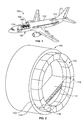
- Figure 1 illustrates an aircraft 100 having one or more stowage carousels 110 formed in accordance with an exemplary embodiment.
- the stowage carousels 110 are used to handle cargo aboard the aircraft 100.
- stowage carousels 110 may handle passenger luggage, such as carry-on luggage and/or storage containers such as standard galley containers.
- the stowage carousel 110 is an annular revolving carousel that accepts the cargo and stows it near the perimeter of the circular fuselage cross-section.
- the aircraft 100 includes a fuselage 102 defining a passenger cabin 104.
- the aircraft 100 includes an upper crown 106 above the passenger cabin 104 and a lower lobe 108 below the passenger cabin 104.
- the upper crown 106 may be defined between a ceiling of the passenger cabin 104 and the fuselage 102
- the lower lobe 108 may be defined below a floor of the passenger cabin 104 and the fuselage 102.
- the stowage carousel 110 may be accessible within the passenger cabin 104.
- the cargo may be loaded into the stowage carousels 110 from within the passenger cabin 104.
- the cargo may be loaded into the stowage carousels 110 from other areas of the aircraft 100, such as from the lower lobe 108.
- the stowage carousel 110 is a mechanized carousel for the cargo where the stowage carousel 110 hugs, such as in close proximity to, the inner mold line of the fuselage 102.
- the stowage carousel extends along an arc path around the fuselage 102.
- the stowage carousel 110 as in the illustrated embodiment, may extend along an arc path that may be a continuous loop (e.g., 360° around the fuselage 102).
- the stowage carousel 110 may extend along a partial arc path, such as from the passenger cabin 104 into the upper crown 106 (as in the embodiment of the stowage carousel 210 shown in Figure 18 ) or from the passenger cabin 104 into the lower lobe 108.
- the stowage carousel 110 includes a plurality of individual stowage compartments receiving different cargo items therein. The stowage compartments may be rotatable with the stowage carousel 110.
- Figure 2 is a perspective view of the stowage carousel 110 in accordance with an exemplary embodiment.
- Figure 2 illustrates the stowage carousel 110 positioned relative to the fuselage 102, and shows the orientation of the stowage carousel 110 relative to a cabin floor 112 of the aircraft 100.
- the stowage carousel 110 is configured to be positioned in close proximity to an interior surface 114 of the fuselage 102.
- the stowage carousel 110 is at least partially rotatable relative to the fuselage 102.
- the stowage carousel 110 passes through the cabin floor 112 such that the stowage carousel 110 is positioned both above the cabin floor 112 and below the cabin floor 112.
- the cargo stowed in the stowage carousel 110 may be stowed at any of multiple positions. For example, at least a portion of the stowage carousel 110 may be clocked to many different predetermined positions to move the cargo.
- the cargo is rotated with the stowage carousel 110 as the portion(s) of the stowage carousel 110 are rotated to the various positions.
- the stowage carousel 110 has a relatively small footprint on the cabin floor 112.
- the stowage carousel 110 has first and second footprints 116 on the cabin floor 112 at opposite first and second sides of the fuselage 102.
- Figure 3 is a cross-sectional view of the aircraft 100 showing the stowage carousel 110 positioned within the fuselage 102.
- the stowage carousel 110 is mounted to the interior of the interior surface 114 of the fuselage 102.
- the stowage carousel 110 is provided in the passenger cabin 104, as well as the upper crown 106 and the lower lobe 108.
- the stowage carousel 110 extends through the cabin floor 112 into the lower lobe 108.
- the cargo may be accessible from the passenger cabin 104, from the lower lobe 108 and/or from the upper crown 106, such as for loading and unloading.
- the stowage carousel 110 includes a wheel or revolving conveyer 120 that is rotatably mounted within the fuselage 102.
- the revolving conveyer 120 is vertically oriented (e.g., in a vertical plane) and defines a walkway 136 through the interior of the revolving conveyer 120 within the passenger cabin 104.
- the walkway 136 may be the form of an archway above the cabin floor 112.
- the walkway 136 is of sufficient height that a person is able to walk therethrough.
- the walkway 136 may have a height from the cabin floor 112 of at least a 95 th percentile height man.
- the walkway 136 may have a height from the cabin floor 112 at least as high as the passenger entryway into the aircraft 100.
- the revolving conveyer 120 includes an inner ring 122 facing the passenger cabin 104 and an outer ring 124 facing the fuselage 102 of the aircraft 100.
- the revolving conveyer 120 is open inside the inner ring 122 and dimensioned for passengers to walk through the revolving conveyer 120.
- the inner and outer rings 122, 124 rotate.
- the inner and outer rings may be stationary and other components of the revolving conveyor 120 may rotate along the inner and outer rings 122, 124.
- a wall or lining 126 is provided interior of the inner ring 122 to cover the revolving conveyer 120 along the archway.
- the revolving conveyer 120 rotates relative to the lining 126.
- the lining 126 faces the passenger cabin 104 and is exposed within the passenger cabin 104.
- the lining 126 may include one or more closable openings that provide access to the revolving conveyer 120 for loading the cargo therein.
- the closable openings may be closed by corresponding doors.
- the lining 126 may extend from the cabin floor 112 at or near a first sidewall 128 of the fuselage 102 upward along the stowage carousel 110.
- the lining 126 may extend across the top or ceiling of the passenger cabin 104.
- the lining 126 may extend back downward along the stowage carousel 110 to the cabin floor 112 at or near a second sidewall 130 of the fuselage 102.
- the inner ring 122 has an inner radius 132 approximately equal to a lining radius dimension of the lining 126.
- the outer ring 124 has an outer radius 134 approximately equal to a sidewall radius dimension of the fuselage 102.
- the stowage carousel 110 includes a track 140 for controlling revolving motion of the revolving conveyer 120.
- the track 140 may include a plurality of rollers 142 for restricting translating movement of the revolving conveyer 120, while allowing rotating movement of the revolving conveyer 120.
- Other types of tracks may be provided in alternatively embodiments for controlling movement of the revolving conveyer 120, such as a rail.
- the track 140 may allow the revolving conveyor 120 to rotate from the passenger cabin 104 to the upper crown 106.
- the track 140 may allow the revolving conveyor 120 to rotate from the passenger cabin 104 to the lower lobe 108.
- the stowage carousel 110 includes a control system 150 for controlling movement of the revolving conveyer 120.
- the control system 150 includes an actuator 152 for controlling the rotated position of the revolving conveyer 120.
- the actuator 152 allows clockwise and counterclockwise movement of the revolving conveyer 120.
- the revolving conveyer 120 may have a predetermined number of preset angular positions and the revolving conveyer 120 is moved to such preset positions.
- the actuator 152 may include an electric motor operably coupled to the revolving conveyer 120.
- the actuator 152 may be coupled to the revolving conveyer 120 by a belt, chain, gear and the like for rotating the revolving conveyer 120.
- the actuator 152 is provided below the cabin floor 112 in the lower lobe 108.
- the actuator 152 is positioned to the interior of the inner ring 122.
- the actuator 152 may be accessed through a floor panel in the cabin floor 112, for example to access a hand crank to control the position of the revolving conveyer 120, such as if the electric motor fails.
- the control system 150 may include a scanner 154 ( Figure 12 ), a user interface 156 ( Figure 12 ), or other components within the passenger cabin 104 for controlling the control system 150.
- the stowage carousel 110 includes a plurality of stowage compartments 160.
- the stowage carousel 110 includes sixteen stowage compartments 160; however any number of stowage compartments 160 may be provided depending on factors such as the size of the revolving conveyor 120 and the size of the stowage compartments 160.
- Each stowage compartment 160 is configured to receive one or more items of cargo 158.
- the stowage compartments 160 may receive carry-on luggage, standard galley containers, or other items.
- the stowage compartments 160 are defined by one or more compartment walls 162.
- each stowage compartment 160 may include compartment walls 162 defining a front (e.g., forward), a rear (e.g., aft), sides, and ends (e.g., bottom and top).
- the front and/or rear may be open to receive the cargo.
- the stowage compartments 160 may include closable doors to close the opening at the front and/or the rear.
- the sides may extend along the inner ring 122 and outer ring 124.
- the sides may define the inner and outer rings 122, 124.
- the stowage compartments 160 are rotated with the revolving conveyer 120 such that, at one position, the compartment wall 162 defining an end may define a bottom of the stowage compartment 160; however, at another position, such same compartment wall 162 may define a top of the stowage compartment 160.
- the stowage compartments 160 may have a gyroscope arrangement where the stowage compartments 160 are rotatable relative to the revolving conveyer 120 such that the bottom wall of the stowage compartment 160 always remains at a bottom of the stowage compartment 160 as the revolving conveyer 120 and the stowage compartment 160 are rotated about the fuselage 102.
- the stowage compartments 160 may be hingedly coupled to the inner ring 122, the outer ring 124 and/or a mounting bracket extending between the inner and outer rings 122, 124.
- the stowage compartments 160 are arcuate shaped and define annular segments.
- the stowage compartments 160 may be approximately trapezoidal shaped having arcuate sides. Other shapes are possible in alternative embodiments.
- the stowage compartments 160 may share compartment walls 162, such as the end walls.
- the stowage compartments 160 may be sized, shaped and dimensioned to receive aircraft standard sized carry-on luggage (e.g., approximately 45cm x 25cm x 56cm).
- the stowage compartments 160 may be sized, shaped and dimensioned to receive aircraft standard galley containers (e.g., approximately 30cm x 42cm x 28cm).
- the stowage compartments 160 may have other sizes in alternative embodiments.
- the revolving conveyor 120 may include different sized stowage compartments 160 for stowing appropriate cargo.
- the cargo may be attached directly to the revolving conveyer 120, such as using a hook, strap, rail or other attachment component and rotated upward or downward by the revolving conveyor 120.
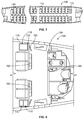
- FIG 4 illustrates the revolving conveyer 120 having a plurality of stowage compartments 170 formed in accordance with an exemplary embodiment.
- the stowage compartments 170 are sized and shaped differently than the stowage compartments 160 (shown in Figure 3 ). In the illustrated embodiment, twenty-four stowage compartments 170 are provided; however any number of stowage compartments 170 may be provided in alternative embodiments.
- the stowage compartments 170 are smaller than the stowage compartments 160 and thus a greater number of stowage compartments 170 are provided in the revolving conveyer 120 between the inner and outer rings 122, 124.
- the stowage compartments 170 are sized, shaped and dimensioned to receive standard galley containers 174. The stowage compartments 170 may be accessed at the front or the rear for loading the galley containers 174 therein.
- the stowage compartments 170 have compartment walls 172.
- the compartment walls 172 are generally circular; however, the compartment walls 172 may have other shapes in alternative embodiments, such as a rectangular shape, an annular segment shape, or another shape.
- the stowage compartments 170 are mounted to mounting brackets 176 between the inner and outer rings 122, 124.
- the mounting brackets 176 may extend across either the front or the rear opposite the openings to the stowage compartments 170.
- the stowage compartments 170 are hingedly coupled to the mounting brackets 176. The stowage compartments 170 are free to rotate relative to the inner and outer rings 122, 124.
- the stowage compartments 170 may maintain the gravitational orientation (e.g., gyroscope arrangement) of such stowage compartments 170. As such, bottoms 178 of the stowage compartments 170 may always remain approximately downward facing.
- Figures 5 and 6 illustrate exemplary locations for the stowage carousel 110 within the aircraft 100.
- Figure 5 shows the passenger cabin 104 without passenger seats showing the stowage carousel 110 near the forward section of the aircraft 100.
- the archway defining the walkway 136 is positioned to the interior of the stowage carousel 110 (shown in phantom in Figure 5).
- Figure 6 shows the stowage carousel 110 near an aft of the aircraft 100, such as near the aft galley of the aircraft 100.
- the stowage carousel 110 may be provided in line with the rear row of passenger seats.
- the rear row of passenger seats may include two passenger seats on each side of the aisle with the stowage carousel 110 positioned between the outer seats and the fuselage 102.
- Figure 7 illustrates the aircraft 100 showing possible locations of the stowage carousels 110.
- Figure 7 illustrates a forward stowage carousel 110 forward of the front row of seats, such as between the front row of seats and the entry door to the aircraft 100.
- a partition wall may be provided between the stowage carousel 110 and the front row of seats.
- the stowage carousel 110 may be accessed at the forward side of the partition wall and stowage carousel 110.
- a door in the partition wall may provide access to the stowage carousel 110 and passengers may load carry-on luggage into the stowage carousel 110 as the passengers enter the aircraft 100 through the entry door.
- a mid-stowage carousel 110 is illustrated in Figure 7 .
- the mid-stowage carousel 110 may be aligned with the wings of the aircraft 100.
- the mid-stowage carousel 110 may be in line with a row of seats.
- the mid-stowage carousel 110 may provide additional stowage for passenger luggage or other items or cargo.
- Figure 7 illustrates an aft stowage carousel 110 at the aft portion of the aircraft 100.
- the aft stowage carousel 110 may be used to supplement stowage for the aft galley.
- galley containers may be loaded into the aft stowage carousel 110.
- the aft stowage carousel 110 may be loaded from the rear of the aft stowage carousel 110.
- FIG 8 is an enlarged view of the aft section of the aircraft 100 showing the aft stowage carousel 110 adjacent the aft galley.
- the stowage carousel 110 may be provided in line with the rear row of passenger seats.
- the stowage compartments 170 ( Figure 4 ) may be accessed through doors 180 in a partition wall 182 behind the rear row of passenger seats.
- the doors 180 may be hingedly coupled to the partition wall 182, such as at the outer edge, the inner edge, a top edge or a bottom edge of the door 180.
- the doors 180 may be at a selected ergonomically appropriate height for loading and unloading, such as at waist level.
- multiple doors may be provided for accessing cargo in different stowage compartments 170.
- the door 180 may be large enough to access cargo in multiple stowage compartments 170.
- the door 180 may be opened and the galley containers 174 may be loaded into corresponding stowage compartments 170.
- the stowage compartments 170 may be successively loaded, such as one or two at a time, by loading the galley container 174 and then rotating the stowage carousel 110 to the next position to load the next galley container 174.
- the galley containers 174 may be unloaded in a similar manner, such as by reversing the process or by continuing to rotate the stowage carousel 110 through an entire 360° loop or to a predetermined position, to access the desired stowage compartment 170.
- the aft galley 184 may be considerably smaller than conventional aft galleys.
- the size of the aft galley 184 may be reduced by 50% or more. Reducing the size of the aft galley 184 allows aft lavatories 186 to be positioned in the space previously occupied by the larger conventional aft galley. For example, in conventional aircraft, the aft lavatories would have been positioned in the location of the rear row of passenger seats and stowage carousel 110 illustrated in Figure 8 .
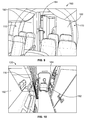
- Figures 9 and 10 illustrate the rear aft stowage carousel 110 in the aircraft 100.
- the stowage carousel 110 is provided in line with the rear row of passenger seats and is accessed from behind the partition wall 182.
- the stowage compartments 170 ( Figure 4 ) are rotated about the stowage carousel 110 such that at least one stowage compartment 170 is positioned along a side of (e.g., in-line with) a passenger seat, at least one stowage compartment 170 is positioned vertically above a passenger seat, and at least one stowage compartment 170 is positioned vertically below a passenger seat.
- the aft galley 184 holds galley carts, but does not need dedicated storage for galley containers 174 ( Figure 4 ) as the galley containers 174 are stowed in the stowage carousel 110.
- Figure 11 illustrates a portion of the aircraft 100 showing the lower lobe 108 with the stowage carousel 110 (shown in phantom) positioned in the lower lobe 108.
- a loading bay 188 may be provided in the lower lobe 108 to access the lower lobe 108 from outside the aircraft 100.
- the loading bay 188 may be provided at or near the aft end of the aircraft 100.
- the stowage carousel 110 may be accessible through the loading bay 188.
- the cargo 158 such as galley containers 174
- the cargo 158 may be loaded into the stowage compartments 170 of the stowage carousel 110 (or unloaded) through the loading bay 188 in the lower lobe 108 of the aircraft 100.
- the catering truck supplying the standard galley containers 174 may load the galley containers 174 through the loading bay 188 at or near ground level as opposed to loading the galley containers 174 into the aft galley through the rear entry door of the aircraft 100.
- Loading through the loading bay 188 at or near ground level may be easier and/or take less time than loading through the rear entry door of the aircraft 100. Such loading may negate the need for special equipment, such as a scissors-lift cargo truck. Optionally, other activities may occur in the aft galley while the galley containers are loaded into the loading bay 188 without needing access to the rear entry by the catering truck.
- the cargo 174 may be accessible within the passenger cabin 104 and may be loaded and/or unloaded in the passenger cabin 104 as well as the lower lobe 108.
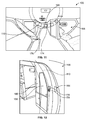
- Figure 12 illustrates the forward entry 164 to the aircraft 100.
- a partition wall 166 is provided at the entry 164.
- a door 168 is provided in a closable opening in the partition wall 166 to access the stowage carousel 110 (shown in phantom in Figure 12 ).
- a scanner 154 is provided at or near the door 168. The scanner 154 forms part of the control system 150 ( Figure 3 ).
- the passenger may enter passenger identification, such as by scanning his or her boarding pass at the scanner 154, to access the stowage carousel 110.
- the scanner 154 may be a fingerprint scanner, a face recognition scanner, a voice recognition scanner or another type of scanner for passenger identification.
- the passenger may open the door 168 and load his or her carry-on luggage into the stowage carousel 110, such as into a certain stowage compartment 160 ( Figure 3 ).
- the control system 150 is able to link the luggage stored in a particular stowage compartment 160 with a particular passenger.
- the passenger may again enter the passenger identification, such as scanning the boarding pass, and the control system 150 may rotate the stowage carousel 110 until the desired stowage compartment 160 is accessible through the door 168.
- the stowage carousel 110 may be restricted from rotating unless the door 168 is in a closed position to avoid injury to passengers.
- the control system 150 may be controlled in other ways in alternative embodiments.
- the user interface 156 may be provided at the partition wall 166.
- the user interface 156 may include a display screen and/or buttons for controlling operation of the stowage carousel 110.
- a user may enter passenger information into the user interface 156, such as entering a seat number or passcode, to control operation of the control system 150.
- Figures 13-17 illustrate exemplary embodiments of stowage carousels 110 on various types of aircraft 100.
- Figure 13 illustrates the stowage carousel 110 on a first aircraft configuration.
- Figure 14 illustrate the stowage carousel 110 on a second aircraft configuration having a larger diameter than the first aircraft configuration.
- the second aircraft configuration includes an upper deck and a lower deck and the stowage carrousel 110 may be accessible in both the upper and lower decks.
- the stowage carousel 110 may be included only in portions of the fuselage 102 having the constant section (e.g., only in the portion of the fuselage 102 having the lower deck so as to not interfere with passenger seating in the upper deck).
- the upper deck may have a partial loop stowage carrousel, such as a stowage carousel that does not penetrate the upper deck floor and that travels along a partial or arched path within the upper passenger cabin area.
- Figure 15 illustrates the stowage carousel 110 on a third aircraft configuration larger than the first aircraft configuration but smaller than the second aircraft configuration.
- Figure 16 illustrates the stowage carousel 110 on a fourth aircraft configuration larger than the third aircraft configuration.
- Figure 17 illustrates the stowage carousel 110 on a fifth aircraft configuration smaller than the fourth aircraft configuration. Because the various aircraft 100 have different diameter fuselages 102, various sized stowage carousels 110 may be provided.
- Larger diameter stowage carousels 110 may have greater number of stowage compartments for stowing more cargo than smaller diameter stowage carousels.
- the stowage carousel 110 may be used in other types of aircraft.
- the stowage carousel 110 may be used in vehicles or applications other than aircraft in alternative embodiments.
- FIG 18 illustrates a stowage carousel 210 formed in accordance with an exemplary embodiment.
- the stowage carousel 210 is similar to the stowage carousel 110 (shown in Figures 1-12 ), except the stowage carousel 210 does not pass through the cabin floor 112 of the aircraft 100. Rather, the stowage carousel 210 is provided above the cabin floor 112 in the passenger cabin 104 and in the upper crown 106.
- the stowage carousel 210 is discontinuous and does not extend entirely circumferentially around the fuselage 102.
- the stowage carousel 210 extends along an arc path extending only partially around the fuselage 102.
- the stowage carousel 210 may include similar components and may be controlled in a similar manner as the stowage carousel 110, such similar or like components and operation not being repeated herein but being applicable to the stowage carousel 210.
- the stowage carousel 210 may be provided in only the upper deck area or only in the lower deck area.
- the stowage carousel 210 includes one or more annular segments.
- the stowage carousel 210 includes two annular segments 212, 214, which may be operated independently.
- the stowage carousel 210 includes a revolving conveyer 220 having a first segment 222 associated with the first segment 212 and a second segment 226 associated with the second segment 214.
- the first segment 222 extends along a first sidewall 224 of the fuselage 102.
- the second segment 226 extends along a second sidewall 228 of the fuselage 102 opposite the first sidewall 224.
- the first and second segments 222, 226 may be revolved or rotated independently from each other.
- the first and second segments 222, 226 are both arc shaped.
- the first segment 222 has a bottom end 230 at or near the cabin floor 112 and a top end 232 opposite the bottom end 230.
- the top end 232 may be provided in the upper crown 106 of the aircraft 100.
- the second segment 226 includes a bottom end 234 at or near the cabin floor 112 and a top end 236 opposite the bottom end 234.
- the top end 236 may be provided in the upper crown 106 of the aircraft 100.
- the first and second segments 222, 224 revolve not just vertically but in an arc shape (and thus partially horizontally) to allow a greater amount of storage capacity in the revolving conveyor than if the stowage carousel 210 only stowed the cargo vertically.
- the arc path may be non-circular, but rather may be elliptical or oval, such as arch-shaped.
- the path may be flatter in some areas, such as along the top.
- the arc shaped segments 222, 226 have a greater stowage capacity per cabin floor footprint than a vertical segment or closet.
- the stowage carousel 210 may be shifted further outward toward the sidewalls 224, 228 allowing a larger walkway through the stowage carousel 210 and/or providing more stowage room inside the stowage carousel 210 (e.g., for a fixed position closet inside the inner ring of the stowage carousel 210).
- the cargo may be loaded into either of the segments 222, 226 of the revolving conveyer 220 and rotated therein.
- the cargo may be loaded into corresponding stowage compartments 240, 242 and rotated within the revolving conveyer 220.
- the cargo may be loaded at an ergonomically convenient height, such as waist level or knee level, and rotated upward around the revolving conveyer 220 to a stowage height that is higher than the loading height.
- the cargo may be loaded at floor level to increase the amount of cargo that may be stowed in the stowage carousel 210.
- the stowage carousel 210 may be unloaded in a reverse direction or reverse operation.
- the lower most stowage compartment 240 may be unloaded and then the revolving conveyer 220 may be rotated in an unloading direction to unload the next stowage compartment 240 successively.
- the cargo may be attached directly to the revolving conveyer 220, such as using a hook or other attachment component and rotated upward or downward by the revolving conveyor 220.
- the lower lobe 108 By not passing through the cabin floor 112, the lower lobe 108 remains unaffected by the stowage carousel 210.
- other components of the aircraft 100 in the lower lobe 108 do not need to be moved or redesigned to fit the stowage carousel 210 in the aircraft 100.
- the stowage carousel 210 may be retrofit into existing aircraft 100 with minimal impact to the aircraft 100. Additionally, because the stowage carousel 210 does not penetrate the cabin floor 112, joists or beams of the cabin floor 112 are unaffected by the stowage carousel 210.
- the stowage carousel 210 may be designed and made deeper (e.g., fore to aft), such as to span multiple floor joists with such design. More cargo may be stored in the deeper stowage compartments, such as two galley containers per stowage compartment or with the longest dimension of the carry-on luggage extending along the depth of the stowage compartment.
- a stowage carousel for handling cargo aboard an aircraft comprising:
- the revolving conveyor is at least partially vertically oriented and defines a walkway interior of the inner ring.
- the outer ring of the revolving conveyor has an outer radius approximately equal to a side wall radius dimension of the fuselage.
- the revolving conveyor is open inside the inner ring and dimensioned for passengers to walk through the revolving conveyor.
- the revolving conveyor is continuous and configured to revolve 360° within the fuselage.
- the revolving conveyor is discontinuous and positioned above a floor of the passenger cabin.
- the revolving conveyor includes a first segment along a first sidewall of the fuselage and a second segment along a second sidewall of the fuselage opposite the first sidewall, the first and second segments being arc shaped, the first and second segments each having a bottom end near the floor and a top end in the upper crown, the top ends of the first and second segments facing each other.
- the revolving conveyor passes through a floor of the passenger cabin at or near a first sidewall of the fuselage and at or near a second sidewall of the fuselage opposite the first sidewall.
- the stowage carousel comprises a lining covering an inside of the revolving conveyor facing the passenger cabin, the lining having a closable opening providing access to the stowage compartments, wherein the stowage compartments are configured to receive the cargo through the closable opening.
- the revolving conveyor is provided in both the upper crown and the lower lobe, the revolving conveyor being rotatable such that the stowage compartments are rotatable from the passenger cabin into the upper crown and from the passenger cabin into the lower lobe.
- the stowage compartments are mounted to the revolving conveyor and are movable with the revolving conveyor.
- the stowage compartments are rotatable relative to the revolving conveyor.
- the stowage compartments include a plurality of compartment walls including a bottom wall, the stowage compartments being hingedly coupled to the revolving conveyor such that the bottom wall remains at a bottom of the stowage compartment as the revolving conveyor and the stowage compartment is rotated about the fuselage.
- the stowage compartments are sized, shaped and dimensioned to receive aircraft standard size carry-on luggage.
- the stowage compartments are sized, shaped and dimensioned to receive aircraft standard galley containers.
- the stowage compartments are configured to be loaded and unloaded in the lower lobe of the aircraft and are configured to be loaded and unloaded in the passenger cabin of the aircraft.
- the stowage carousel comprises a control system operably coupled to the revolving conveyor, the control system having an actuator causing the revolving conveyor to rotate, the control system controlling a position of the revolving conveyor with respect to the fuselage.
- control system comprises a user interface for controlling operation of the revolving conveyor, the user interface being accessible within the passenger cabin.
- control system comprises a scanner configured to scan passenger identification of a passenger to operate the revolving conveyor to rotate to a position for the passenger to retrieve cargo.
- the revolving conveyor is configured to be positioned in line with a row of passenger seats such that the revolving conveyor is positioned between the fuselage and at least one passenger seat.
- the revolving conveyor is configured to be positioned in the aircraft such that at least one stowage compartment is positioned along a side of a passenger seat, at least one stowage compartment is positioned vertically above a passenger seat, and at least one stowage compartment is positioned vertically below a passenger seat.
- a method of stowing cargo aboard an aircraft comprising:
- the method comprises:
- the method comprises operating a control system to control the position of the revolving stowage carousel to place different cargo into a different stowage compartment of the stowage carousel.
- operating the control system comprises scanning a passenger boarding pass at or near the opening to control positioning of the revolving stowage carousel.
- said rotating the revolving stowage carousel comprises rotating the cargo through an arc shaped path along a sidewall of a fuselage of the aircraft.
- said rotating the revolving stowage carousel comprises rotating the cargo into an upper crown of the aircraft.
- said rotating the revolving stowage carousel comprises rotating the cargo into a lower lobe of the aircraft.
- said rotating the revolving stowage carousel comprises rotating the cargo through a continuous 360° loop around the fuselage of the aircraft.
- said rotating the revolving stowage carousel comprises rotating the cargo through a cabin floor of the aircraft.
- said placing the cargo into a revolving stowage carousel comprises placing the cargo into a dedicated stowage compartment of the stowage carousel, the stowage compartment being rotatable with the stowage carousel.
Landscapes
- Engineering & Computer Science (AREA)
- Aviation & Aerospace Engineering (AREA)
- Mechanical Engineering (AREA)
- Packaging Of Machine Parts And Wound Products (AREA)
- Warehouses Or Storage Devices (AREA)
- Tires In General (AREA)
- Passenger Equipment (AREA)
Abstract
Description
- The present disclosure relates generally to systems and methods of stowage of cargo on an aircraft using a stowage carousel.
- Stowage of cargo on aircraft is problematic. The aircraft has space dedicated to different functions and optimizing the space is important. For example, space is dedicated to passengers in the passenger cabin in the form of passenger seats. Each seat on the aircraft adds to the ability for the airline to generate revenue for each flight. Therefore, it is desirable to maximize the number of passenger seats on an aircraft, taking into consideration passenger safety, comfort and the like. However, some space on the aircraft must be dedicated to other functions such as stowage of cargo, galley operation, lavatories, and the like.
- Presently, more and more passengers are carrying hand luggage into the passenger cabin in lieu of checking the luggage and having the luggage stowed in the lower lobe of the aircraft. The increase in the amount of carry-on luggage has put increased pressure on overhead stow bin capacities and volumes. Some closets are provided in the passenger cabin for additional stowage, however, such closets occupy valuable floor space on the aircraft, taking space that could otherwise be used for revenue generating passenger seats.
- Additionally, many aircraft have multiple, large galleys to store food and beverages on the aircraft. The food and beverages are typically stored in galley carts and galley containers which are transported to the aircraft and stored in compartments in the galleys. The large number of galley containers used on the aircraft occupy a significant amount of space, and have led to larger galley footprints on the aircraft. Reduction in galley footprints would allow additional space to be utilized for revenue generating passenger seats.
- In accordance with one embodiment, a stowage carousel for handling cargo aboard an aircraft is provided including a revolving conveyor having an inner ring facing a passenger cabin of the aircraft and an outer ring facing a fuselage of the aircraft. Stowage compartments are associated with the revolving conveyor. The stowage compartments are configured to receive the cargo. The stowage compartments are rotatable within the aircraft with the revolving conveyor. The revolving conveyor is situated within the aircraft partially in the passenger cabin and partially in at least one of an upper crown and a lower lobe of the aircraft.
- In another embodiment, a method of stowing cargo aboard an aircraft is provided including moving the cargo into a passenger cabin of the aircraft, placing the cargo into a revolving stowage carousel via an opening and rotating the revolving stowage carousel to stow the cargo.
- The features and functions that have been discussed can be achieved independently in various embodiments or may be combined in yet other embodiments, further details of which can be seen with reference to the following description and drawings.
-
-
Figure 1 illustrates an aircraft having one or more stowage carousels formed in accordance with an exemplary embodiment. -
Figure 2 is a perspective view of the stowage carousel in accordance with an exemplary embodiment. -
Figure 3 is a cross-sectional view of the aircraft showing the stowage carousel positioned within a fuselage of the aircraft. -
Figure 4 illustrates a revolving conveyer of the stowage carousel having a plurality of stowage compartments formed in accordance with an exemplary embodiment. -
Figures 5 and 6 illustrate exemplary locations for the stowage carousel within the aircraft. -
Figure 7 illustrates the aircraft showing possible locations of the stowage carousels. -
Figure 8 is an enlarged view of an aft section of the aircraft showing the stowage carousel adjacent an aft galley in accordance with an exemplary embodiment. -
Figures 9 and 10 illustrate the stowage carousel in the aircraft in accordance with an exemplary embodiment. -
Figure 11 illustrates a portion of the aircraft showing a lower lobe with the stowage carousel positioned therein. -
Figure 12 illustrates a forward entry of the aircraft showing a possible location of the stowage carousel. -
Figures 13-17 illustrate exemplary embodiments of stowage carousels on various types of aircraft. -
Figure 18 illustrates a stowage carousel formed in accordance with an exemplary embodiment. - The following detailed description of certain embodiments will be better understood when read in conjunction with the appended drawings. It should be understood that the various embodiments are not limited to the arrangements and instrumentality shown in the drawings.
- As used herein, an element or step recited in the singular and proceeded with the word "a" or "an" should be understood as not excluding plural of said elements or steps, unless such exclusion is explicitly stated. Furthermore, references to "one embodiment" are not intended to be interpreted as excluding the existence of additional embodiments that also incorporate the recited features. Moreover, unless explicitly stated to the contrary, embodiments "comprising" or "having" an element or a plurality of elements having a particular property may include additional such elements not having that property.
- Described herein are various embodiments of a stowage carousel for an aircraft configured to stow cargo such as carry-on luggage, standard galley containers for galleys, and the like. Various embodiments provide a revolving, annular carousel that rotates along an arc path that accepts the cargo and stores the cargo near the perimeter of the fuselage. The carousel may be a continuous loop in various embodiments. The carousel may be a partial loop in other various embodiments. The carousel may be used to store the cargo in the upper crown of the aircraft and/or in the lower lobe of the aircraft as well as along sidewalls of the fuselage. The stowage carousel utilizes the vertical height of the aircraft, while providing usable access to the valuable floor space by stowing the cargo above and/or below the passenger cabin. The valuable floor space may thus be dedicated to other purposes, such as passenger seats, to potentially increase the yearly revenue stream of the aircraft. In various embodiments, the stowage carousel may store cargo previously stored in a galley, thus reducing the size of the galley on the aircraft for other uses, such as to provide a space for a lavatory or for additional passenger seats.
-
Figure 1 illustrates anaircraft 100 having one ormore stowage carousels 110 formed in accordance with an exemplary embodiment. Thestowage carousels 110 are used to handle cargo aboard theaircraft 100. For example,stowage carousels 110 may handle passenger luggage, such as carry-on luggage and/or storage containers such as standard galley containers. Thestowage carousel 110 is an annular revolving carousel that accepts the cargo and stows it near the perimeter of the circular fuselage cross-section. - The
aircraft 100 includes afuselage 102 defining apassenger cabin 104. Theaircraft 100 includes anupper crown 106 above thepassenger cabin 104 and alower lobe 108 below thepassenger cabin 104. For example, theupper crown 106 may be defined between a ceiling of thepassenger cabin 104 and thefuselage 102, while thelower lobe 108 may be defined below a floor of thepassenger cabin 104 and thefuselage 102. Thestowage carousel 110 may be accessible within thepassenger cabin 104. For example, the cargo may be loaded into thestowage carousels 110 from within thepassenger cabin 104. In other various embodiments, the cargo may be loaded into thestowage carousels 110 from other areas of theaircraft 100, such as from thelower lobe 108. - The
stowage carousel 110 is a mechanized carousel for the cargo where thestowage carousel 110 hugs, such as in close proximity to, the inner mold line of thefuselage 102. The stowage carousel extends along an arc path around thefuselage 102. Thestowage carousel 110, as in the illustrated embodiment, may extend along an arc path that may be a continuous loop (e.g., 360° around the fuselage 102). Alternatively, thestowage carousel 110 may extend along a partial arc path, such as from thepassenger cabin 104 into the upper crown 106 (as in the embodiment of thestowage carousel 210 shown inFigure 18 ) or from thepassenger cabin 104 into thelower lobe 108. In an exemplary embodiment, thestowage carousel 110 includes a plurality of individual stowage compartments receiving different cargo items therein. The stowage compartments may be rotatable with thestowage carousel 110. -
Figure 2 is a perspective view of thestowage carousel 110 in accordance with an exemplary embodiment.Figure 2 illustrates thestowage carousel 110 positioned relative to thefuselage 102, and shows the orientation of thestowage carousel 110 relative to acabin floor 112 of theaircraft 100. Thestowage carousel 110 is configured to be positioned in close proximity to aninterior surface 114 of thefuselage 102. Thestowage carousel 110 is at least partially rotatable relative to thefuselage 102. - In an exemplary embodiment, the
stowage carousel 110 passes through thecabin floor 112 such that thestowage carousel 110 is positioned both above thecabin floor 112 and below thecabin floor 112. The cargo stowed in thestowage carousel 110 may be stowed at any of multiple positions. For example, at least a portion of thestowage carousel 110 may be clocked to many different predetermined positions to move the cargo. The cargo is rotated with thestowage carousel 110 as the portion(s) of thestowage carousel 110 are rotated to the various positions. As such, a large number of cargo items may be stowed in thestowage carousel 110, while thestowage carousel 110 has a relatively small footprint on thecabin floor 112. For example, thestowage carousel 110 has first andsecond footprints 116 on thecabin floor 112 at opposite first and second sides of thefuselage 102. -
Figure 3 is a cross-sectional view of theaircraft 100 showing thestowage carousel 110 positioned within thefuselage 102. Thestowage carousel 110 is mounted to the interior of theinterior surface 114 of thefuselage 102. In the illustrated embodiment, thestowage carousel 110 is provided in thepassenger cabin 104, as well as theupper crown 106 and thelower lobe 108. Thestowage carousel 110 extends through thecabin floor 112 into thelower lobe 108. The cargo may be accessible from thepassenger cabin 104, from thelower lobe 108 and/or from theupper crown 106, such as for loading and unloading. - The
stowage carousel 110 includes a wheel or revolvingconveyer 120 that is rotatably mounted within thefuselage 102. The revolvingconveyer 120 is vertically oriented (e.g., in a vertical plane) and defines awalkway 136 through the interior of the revolvingconveyer 120 within thepassenger cabin 104. Thewalkway 136 may be the form of an archway above thecabin floor 112. Thewalkway 136 is of sufficient height that a person is able to walk therethrough. For example, thewalkway 136 may have a height from thecabin floor 112 of at least a 95th percentile height man. Thewalkway 136 may have a height from thecabin floor 112 at least as high as the passenger entryway into theaircraft 100. The revolvingconveyer 120 includes aninner ring 122 facing thepassenger cabin 104 and anouter ring 124 facing thefuselage 102 of theaircraft 100. The revolvingconveyer 120 is open inside theinner ring 122 and dimensioned for passengers to walk through the revolvingconveyer 120. In an exemplary embodiment, the inner andouter rings conveyor 120 may rotate along the inner andouter rings - In an exemplary embodiment, a wall or lining 126 is provided interior of the
inner ring 122 to cover the revolvingconveyer 120 along the archway. The revolvingconveyer 120 rotates relative to thelining 126. The lining 126 faces thepassenger cabin 104 and is exposed within thepassenger cabin 104. Optionally, the lining 126 may include one or more closable openings that provide access to the revolvingconveyer 120 for loading the cargo therein. The closable openings may be closed by corresponding doors. The lining 126 may extend from thecabin floor 112 at or near afirst sidewall 128 of thefuselage 102 upward along thestowage carousel 110. The lining 126 may extend across the top or ceiling of thepassenger cabin 104. The lining 126 may extend back downward along thestowage carousel 110 to thecabin floor 112 at or near asecond sidewall 130 of thefuselage 102. Theinner ring 122 has aninner radius 132 approximately equal to a lining radius dimension of thelining 126. Theouter ring 124 has anouter radius 134 approximately equal to a sidewall radius dimension of thefuselage 102. - The
stowage carousel 110 includes atrack 140 for controlling revolving motion of the revolvingconveyer 120. For example, thetrack 140 may include a plurality ofrollers 142 for restricting translating movement of the revolvingconveyer 120, while allowing rotating movement of the revolvingconveyer 120. Other types of tracks may be provided in alternatively embodiments for controlling movement of the revolvingconveyer 120, such as a rail. Thetrack 140 may allow the revolvingconveyor 120 to rotate from thepassenger cabin 104 to theupper crown 106. Thetrack 140 may allow the revolvingconveyor 120 to rotate from thepassenger cabin 104 to thelower lobe 108. - The
stowage carousel 110 includes acontrol system 150 for controlling movement of the revolvingconveyer 120. In an exemplary embodiment, thecontrol system 150 includes anactuator 152 for controlling the rotated position of the revolvingconveyer 120. In an exemplary embodiment, theactuator 152 allows clockwise and counterclockwise movement of the revolvingconveyer 120. Optionally, the revolvingconveyer 120 may have a predetermined number of preset angular positions and the revolvingconveyer 120 is moved to such preset positions. - The
actuator 152 may include an electric motor operably coupled to the revolvingconveyer 120. For example, theactuator 152 may be coupled to the revolvingconveyer 120 by a belt, chain, gear and the like for rotating the revolvingconveyer 120. In the illustrated embodiment, theactuator 152 is provided below thecabin floor 112 in thelower lobe 108. Theactuator 152 is positioned to the interior of theinner ring 122. Optionally, theactuator 152 may be accessed through a floor panel in thecabin floor 112, for example to access a hand crank to control the position of the revolvingconveyer 120, such as if the electric motor fails. Optionally, thecontrol system 150 may include a scanner 154 (Figure 12 ), a user interface 156 (Figure 12 ), or other components within thepassenger cabin 104 for controlling thecontrol system 150. - In an exemplary embodiment, the
stowage carousel 110 includes a plurality of stowage compartments 160. In the illustrated embodiment, thestowage carousel 110 includes sixteenstowage compartments 160; however any number ofstowage compartments 160 may be provided depending on factors such as the size of the revolvingconveyor 120 and the size of the stowage compartments 160. Eachstowage compartment 160 is configured to receive one or more items ofcargo 158. For example, the stowage compartments 160 may receive carry-on luggage, standard galley containers, or other items. Optionally, the stowage compartments 160 are defined by one ormore compartment walls 162. For example, eachstowage compartment 160 may includecompartment walls 162 defining a front (e.g., forward), a rear (e.g., aft), sides, and ends (e.g., bottom and top). The front and/or rear may be open to receive the cargo. The stowage compartments 160 may include closable doors to close the opening at the front and/or the rear. The sides may extend along theinner ring 122 andouter ring 124. Optionally, the sides may define the inner andouter rings - The stowage compartments 160 are rotated with the revolving
conveyer 120 such that, at one position, thecompartment wall 162 defining an end may define a bottom of thestowage compartment 160; however, at another position, suchsame compartment wall 162 may define a top of thestowage compartment 160. Alternatively, in other various embodiments, the stowage compartments 160 may have a gyroscope arrangement where the stowage compartments 160 are rotatable relative to the revolvingconveyer 120 such that the bottom wall of thestowage compartment 160 always remains at a bottom of thestowage compartment 160 as the revolvingconveyer 120 and thestowage compartment 160 are rotated about thefuselage 102. For example, the stowage compartments 160 may be hingedly coupled to theinner ring 122, theouter ring 124 and/or a mounting bracket extending between the inner andouter rings - In an exemplary embodiment, the stowage compartments 160 are arcuate shaped and define annular segments. For example, the stowage compartments 160 may be approximately trapezoidal shaped having arcuate sides. Other shapes are possible in alternative embodiments. Optionally, the stowage compartments 160 may share
compartment walls 162, such as the end walls. Optionally, the stowage compartments 160 may be sized, shaped and dimensioned to receive aircraft standard sized carry-on luggage (e.g., approximately 45cm x 25cm x 56cm). The stowage compartments 160 may be sized, shaped and dimensioned to receive aircraft standard galley containers (e.g., approximately 30cm x 42cm x 28cm). The stowage compartments 160 may have other sizes in alternative embodiments. Optionally, the revolvingconveyor 120 may include different sized stowage compartments 160 for stowing appropriate cargo. In other alternative embodiments, rather than pre-sized stowage compartments 160 with walls, the cargo may be attached directly to the revolvingconveyer 120, such as using a hook, strap, rail or other attachment component and rotated upward or downward by the revolvingconveyor 120. -
Figure 4 illustrates the revolvingconveyer 120 having a plurality ofstowage compartments 170 formed in accordance with an exemplary embodiment. The stowage compartments 170 are sized and shaped differently than the stowage compartments 160 (shown inFigure 3 ). In the illustrated embodiment, twenty-fourstowage compartments 170 are provided; however any number ofstowage compartments 170 may be provided in alternative embodiments. The stowage compartments 170 are smaller than the stowage compartments 160 and thus a greater number ofstowage compartments 170 are provided in the revolvingconveyer 120 between the inner andouter rings standard galley containers 174. The stowage compartments 170 may be accessed at the front or the rear for loading thegalley containers 174 therein. - The stowage compartments 170 have
compartment walls 172. In the illustrated embodiment, thecompartment walls 172 are generally circular; however, thecompartment walls 172 may have other shapes in alternative embodiments, such as a rectangular shape, an annular segment shape, or another shape. In an exemplary embodiment, the stowage compartments 170 are mounted to mountingbrackets 176 between the inner andouter rings brackets 176 may extend across either the front or the rear opposite the openings to the stowage compartments 170. In an exemplary embodiment, the stowage compartments 170 are hingedly coupled to the mountingbrackets 176. The stowage compartments 170 are free to rotate relative to the inner andouter rings bottoms 178 of the stowage compartments 170 may always remain approximately downward facing. -
Figures 5 and 6 illustrate exemplary locations for thestowage carousel 110 within theaircraft 100.Figure 5 shows thepassenger cabin 104 without passenger seats showing thestowage carousel 110 near the forward section of theaircraft 100. The archway defining thewalkway 136 is positioned to the interior of the stowage carousel 110 (shown in phantom inFigure 5). Figure 6 shows thestowage carousel 110 near an aft of theaircraft 100, such as near the aft galley of theaircraft 100. Optionally, the stowage carousel 110 (shown in phantom inFigure 6 ) may be provided in line with the rear row of passenger seats. For example, the rear row of passenger seats may include two passenger seats on each side of the aisle with thestowage carousel 110 positioned between the outer seats and thefuselage 102. -
Figure 7 illustrates theaircraft 100 showing possible locations of thestowage carousels 110. For example,Figure 7 illustrates aforward stowage carousel 110 forward of the front row of seats, such as between the front row of seats and the entry door to theaircraft 100. A partition wall may be provided between thestowage carousel 110 and the front row of seats. Thestowage carousel 110 may be accessed at the forward side of the partition wall andstowage carousel 110. For example, a door in the partition wall may provide access to thestowage carousel 110 and passengers may load carry-on luggage into thestowage carousel 110 as the passengers enter theaircraft 100 through the entry door. - A
mid-stowage carousel 110 is illustrated inFigure 7 . For example, themid-stowage carousel 110 may be aligned with the wings of theaircraft 100. Themid-stowage carousel 110 may be in line with a row of seats. Themid-stowage carousel 110 may provide additional stowage for passenger luggage or other items or cargo. -
Figure 7 illustrates anaft stowage carousel 110 at the aft portion of theaircraft 100. Theaft stowage carousel 110 may be used to supplement stowage for the aft galley. For example, galley containers may be loaded into theaft stowage carousel 110. Theaft stowage carousel 110 may be loaded from the rear of theaft stowage carousel 110. -
Figure 8 is an enlarged view of the aft section of theaircraft 100 showing theaft stowage carousel 110 adjacent the aft galley. Thestowage carousel 110 may be provided in line with the rear row of passenger seats. The stowage compartments 170 (Figure 4 ) may be accessed throughdoors 180 in apartition wall 182 behind the rear row of passenger seats. Thedoors 180 may be hingedly coupled to thepartition wall 182, such as at the outer edge, the inner edge, a top edge or a bottom edge of thedoor 180. Thedoors 180 may be at a selected ergonomically appropriate height for loading and unloading, such as at waist level. Optionally, multiple doors may be provided for accessing cargo in different stowage compartments 170. Optionally, thedoor 180 may be large enough to access cargo in multiple stowage compartments 170. Thedoor 180 may be opened and thegalley containers 174 may be loaded into corresponding stowage compartments 170. The stowage compartments 170 may be successively loaded, such as one or two at a time, by loading thegalley container 174 and then rotating thestowage carousel 110 to the next position to load thenext galley container 174. Thegalley containers 174 may be unloaded in a similar manner, such as by reversing the process or by continuing to rotate thestowage carousel 110 through an entire 360° loop or to a predetermined position, to access the desiredstowage compartment 170. - By storing a plurality of the
galley containers 174 in thestowage carousel 110 theaft galley 184 may be considerably smaller than conventional aft galleys. For example, the size of theaft galley 184 may be reduced by 50% or more. Reducing the size of theaft galley 184 allowsaft lavatories 186 to be positioned in the space previously occupied by the larger conventional aft galley. For example, in conventional aircraft, the aft lavatories would have been positioned in the location of the rear row of passenger seats andstowage carousel 110 illustrated inFigure 8 . By moving theaft lavatories 186 rearward into the space previously occupied by theaft galley 184, an additional row of passenger seats may be provided in theaircraft 100. As such, revenue generation per flight of theaircraft 100 may be increased by the use of thestowage carousel 110 holding a plurality of thegalley containers 174. -
Figures 9 and 10 illustrate the rearaft stowage carousel 110 in theaircraft 100. Thestowage carousel 110 is provided in line with the rear row of passenger seats and is accessed from behind thepartition wall 182. In an exemplary embodiment, the stowage compartments 170 (Figure 4 ) are rotated about thestowage carousel 110 such that at least onestowage compartment 170 is positioned along a side of (e.g., in-line with) a passenger seat, at least onestowage compartment 170 is positioned vertically above a passenger seat, and at least onestowage compartment 170 is positioned vertically below a passenger seat. Theaft galley 184 holds galley carts, but does not need dedicated storage for galley containers 174 (Figure 4 ) as thegalley containers 174 are stowed in thestowage carousel 110. -
Figure 11 illustrates a portion of theaircraft 100 showing thelower lobe 108 with the stowage carousel 110 (shown in phantom) positioned in thelower lobe 108. In an exemplary embodiment, aloading bay 188 may be provided in thelower lobe 108 to access thelower lobe 108 from outside theaircraft 100. For example, theloading bay 188 may be provided at or near the aft end of theaircraft 100. Thestowage carousel 110 may be accessible through theloading bay 188. As such, thecargo 158, such asgalley containers 174, may be loaded into the stowage compartments 170 of the stowage carousel 110 (or unloaded) through theloading bay 188 in thelower lobe 108 of theaircraft 100. For example, the catering truck supplying thestandard galley containers 174 may load thegalley containers 174 through theloading bay 188 at or near ground level as opposed to loading thegalley containers 174 into the aft galley through the rear entry door of theaircraft 100. - Loading through the
loading bay 188 at or near ground level may be easier and/or take less time than loading through the rear entry door of theaircraft 100. Such loading may negate the need for special equipment, such as a scissors-lift cargo truck. Optionally, other activities may occur in the aft galley while the galley containers are loaded into theloading bay 188 without needing access to the rear entry by the catering truck. Thecargo 174 may be accessible within thepassenger cabin 104 and may be loaded and/or unloaded in thepassenger cabin 104 as well as thelower lobe 108. -
Figure 12 illustrates theforward entry 164 to theaircraft 100. Apartition wall 166 is provided at theentry 164. Adoor 168 is provided in a closable opening in thepartition wall 166 to access the stowage carousel 110 (shown in phantom inFigure 12 ). In an exemplary embodiment, ascanner 154 is provided at or near thedoor 168. Thescanner 154 forms part of the control system 150 (Figure 3 ). - When a passenger enters the
aircraft 100 through theentry 164, the passenger may enter passenger identification, such as by scanning his or her boarding pass at thescanner 154, to access thestowage carousel 110. In other various embodiments, thescanner 154 may be a fingerprint scanner, a face recognition scanner, a voice recognition scanner or another type of scanner for passenger identification. The passenger may open thedoor 168 and load his or her carry-on luggage into thestowage carousel 110, such as into a certain stowage compartment 160 (Figure 3 ). By entering passenger identification, thecontrol system 150 is able to link the luggage stored in aparticular stowage compartment 160 with a particular passenger. When the passenger needs to access his or her luggage, the passenger may again enter the passenger identification, such as scanning the boarding pass, and thecontrol system 150 may rotate thestowage carousel 110 until the desiredstowage compartment 160 is accessible through thedoor 168. Optionally, thestowage carousel 110 may be restricted from rotating unless thedoor 168 is in a closed position to avoid injury to passengers. - The
control system 150 may be controlled in other ways in alternative embodiments. For example, theuser interface 156 may be provided at thepartition wall 166. Theuser interface 156 may include a display screen and/or buttons for controlling operation of thestowage carousel 110. For example, a user may enter passenger information into theuser interface 156, such as entering a seat number or passcode, to control operation of thecontrol system 150. -
Figures 13-17 illustrate exemplary embodiments ofstowage carousels 110 on various types ofaircraft 100.Figure 13 illustrates thestowage carousel 110 on a first aircraft configuration.Figure 14 illustrate thestowage carousel 110 on a second aircraft configuration having a larger diameter than the first aircraft configuration. The second aircraft configuration includes an upper deck and a lower deck and thestowage carrousel 110 may be accessible in both the upper and lower decks. Alternatively, thestowage carousel 110 may be included only in portions of thefuselage 102 having the constant section (e.g., only in the portion of thefuselage 102 having the lower deck so as to not interfere with passenger seating in the upper deck). In other alternative embodiments, the upper deck may have a partial loop stowage carrousel, such as a stowage carousel that does not penetrate the upper deck floor and that travels along a partial or arched path within the upper passenger cabin area.Figure 15 illustrates thestowage carousel 110 on a third aircraft configuration larger than the first aircraft configuration but smaller than the second aircraft configuration.Figure 16 illustrates thestowage carousel 110 on a fourth aircraft configuration larger than the third aircraft configuration.Figure 17 illustrates thestowage carousel 110 on a fifth aircraft configuration smaller than the fourth aircraft configuration. Because thevarious aircraft 100 havedifferent diameter fuselages 102, varioussized stowage carousels 110 may be provided. Largerdiameter stowage carousels 110 may have greater number of stowage compartments for stowing more cargo than smaller diameter stowage carousels. Thestowage carousel 110 may be used in other types of aircraft. Thestowage carousel 110 may be used in vehicles or applications other than aircraft in alternative embodiments. -
Figure 18 illustrates astowage carousel 210 formed in accordance with an exemplary embodiment. Thestowage carousel 210 is similar to the stowage carousel 110 (shown inFigures 1-12 ), except thestowage carousel 210 does not pass through thecabin floor 112 of theaircraft 100. Rather, thestowage carousel 210 is provided above thecabin floor 112 in thepassenger cabin 104 and in theupper crown 106. Thestowage carousel 210 is discontinuous and does not extend entirely circumferentially around thefuselage 102. Thestowage carousel 210 extends along an arc path extending only partially around thefuselage 102. Thestowage carousel 210 may include similar components and may be controlled in a similar manner as thestowage carousel 110, such similar or like components and operation not being repeated herein but being applicable to thestowage carousel 210. Optionally, such as when used on a multi-deck aircraft, thestowage carousel 210 may be provided in only the upper deck area or only in the lower deck area. - The
stowage carousel 210 includes one or more annular segments. For example, in the illustrated embodiment, thestowage carousel 210 includes twoannular segments stowage carousel 210 includes a revolvingconveyer 220 having afirst segment 222 associated with thefirst segment 212 and asecond segment 226 associated with thesecond segment 214. Thefirst segment 222 extends along afirst sidewall 224 of thefuselage 102. Thesecond segment 226 extends along asecond sidewall 228 of thefuselage 102 opposite thefirst sidewall 224. The first andsecond segments second segments first segment 222 has abottom end 230 at or near thecabin floor 112 and atop end 232 opposite thebottom end 230. Thetop end 232 may be provided in theupper crown 106 of theaircraft 100. Thesecond segment 226 includes abottom end 234 at or near thecabin floor 112 and atop end 236 opposite thebottom end 234. Thetop end 236 may be provided in theupper crown 106 of theaircraft 100. In an exemplary embodiment, the top ends 232, 236 of the first andsecond segments aircraft 100. The first andsecond segments stowage carousel 210 only stowed the cargo vertically. Optionally, the arc path may be non-circular, but rather may be elliptical or oval, such as arch-shaped. For example, the path may be flatter in some areas, such as along the top. The arc shapedsegments segments stowage carousel 210 may be shifted further outward toward thesidewalls stowage carousel 210 and/or providing more stowage room inside the stowage carousel 210 (e.g., for a fixed position closet inside the inner ring of the stowage carousel 210). - The cargo may be loaded into either of the
segments conveyer 220 and rotated therein. For example, the cargo may be loaded into corresponding stowage compartments 240, 242 and rotated within the revolvingconveyer 220. The cargo may be loaded at an ergonomically convenient height, such as waist level or knee level, and rotated upward around the revolvingconveyer 220 to a stowage height that is higher than the loading height. The cargo may be loaded at floor level to increase the amount of cargo that may be stowed in thestowage carousel 210. Thestowage carousel 210 may be unloaded in a reverse direction or reverse operation. For example, the lowermost stowage compartment 240 may be unloaded and then the revolvingconveyer 220 may be rotated in an unloading direction to unload thenext stowage compartment 240 successively. Optionally, rather than pre-sized stowage compartments 240, the cargo may be attached directly to the revolvingconveyer 220, such as using a hook or other attachment component and rotated upward or downward by the revolvingconveyor 220. - By not passing through the
cabin floor 112, thelower lobe 108 remains unaffected by thestowage carousel 210. For example, other components of theaircraft 100 in thelower lobe 108 do not need to be moved or redesigned to fit thestowage carousel 210 in theaircraft 100. Thestowage carousel 210 may be retrofit into existingaircraft 100 with minimal impact to theaircraft 100. Additionally, because thestowage carousel 210 does not penetrate thecabin floor 112, joists or beams of thecabin floor 112 are unaffected by thestowage carousel 210. Optionally, thestowage carousel 210 may be designed and made deeper (e.g., fore to aft), such as to span multiple floor joists with such design. More cargo may be stored in the deeper stowage compartments, such as two galley containers per stowage compartment or with the longest dimension of the carry-on luggage extending along the depth of the stowage compartment. - According to another aspect, there is provided a stowage carousel for handling cargo aboard an aircraft, the stowage carousel comprising:
- a revolving conveyor having an inner ring facing a passenger cabin of the aircraft and an outer ring facing a fuselage of the aircraft; and
- stowage compartments associated with the revolving conveyor, the stowage compartments being configured to receive the cargo, the stowage compartments being rotatable within the aircraft,
- wherein the revolving conveyor is situated within the aircraft partially in the passenger cabin and partially in at least one of the upper crown and the lower lobe of the aircraft.
- Optionally, the revolving conveyor is at least partially vertically oriented and defines a walkway interior of the inner ring.
- Optionally, the outer ring of the revolving conveyor has an outer radius approximately equal to a side wall radius dimension of the fuselage.
- Optionally, the revolving conveyor is open inside the inner ring and dimensioned for passengers to walk through the revolving conveyor.
- Optionally, the revolving conveyor is continuous and configured to revolve 360° within the fuselage.
- Optionally, the revolving conveyor is discontinuous and positioned above a floor of the passenger cabin.
- Optionally, the revolving conveyor includes a first segment along a first sidewall of the fuselage and a second segment along a second sidewall of the fuselage opposite the first sidewall, the first and second segments being arc shaped, the first and second segments each having a bottom end near the floor and a top end in the upper crown, the top ends of the first and second segments facing each other.
- Optionally, the revolving conveyor passes through a floor of the passenger cabin at or near a first sidewall of the fuselage and at or near a second sidewall of the fuselage opposite the first sidewall.
- Optionally, the stowage carousel comprises a lining covering an inside of the revolving conveyor facing the passenger cabin, the lining having a closable opening providing access to the stowage compartments, wherein the stowage compartments are configured to receive the cargo through the closable opening.
- Optionally, the revolving conveyor is provided in both the upper crown and the lower lobe, the revolving conveyor being rotatable such that the stowage compartments are rotatable from the passenger cabin into the upper crown and from the passenger cabin into the lower lobe.
- Optionally, the stowage compartments are mounted to the revolving conveyor and are movable with the revolving conveyor.
- Optionally, the stowage compartments are rotatable relative to the revolving conveyor.
- Optionally, the stowage compartments include a plurality of compartment walls including a bottom wall, the stowage compartments being hingedly coupled to the revolving conveyor such that the bottom wall remains at a bottom of the stowage compartment as the revolving conveyor and the stowage compartment is rotated about the fuselage.
- Optionally, the stowage compartments are sized, shaped and dimensioned to receive aircraft standard size carry-on luggage.
- Optionally, the stowage compartments are sized, shaped and dimensioned to receive aircraft standard galley containers.
- Optionally, the stowage compartments are configured to be loaded and unloaded in the lower lobe of the aircraft and are configured to be loaded and unloaded in the passenger cabin of the aircraft.
- Optionally, the stowage carousel comprises a control system operably coupled to the revolving conveyor, the control system having an actuator causing the revolving conveyor to rotate, the control system controlling a position of the revolving conveyor with respect to the fuselage.
- Optionally, the control system comprises a user interface for controlling operation of the revolving conveyor, the user interface being accessible within the passenger cabin.
- Optionally, the control system comprises a scanner configured to scan passenger identification of a passenger to operate the revolving conveyor to rotate to a position for the passenger to retrieve cargo.
- Optionally, the revolving conveyor is configured to be positioned in line with a row of passenger seats such that the revolving conveyor is positioned between the fuselage and at least one passenger seat.
- Optionally, the revolving conveyor is configured to be positioned in the aircraft such that at least one stowage compartment is positioned along a side of a passenger seat, at least one stowage compartment is positioned vertically above a passenger seat, and at least one stowage compartment is positioned vertically below a passenger seat.
- According to another aspect, there is provided a method of stowing cargo aboard an aircraft, the method comprising:
- moving the cargo into a passenger cabin of the aircraft;
- placing the cargo into a revolving stowage carousel via an opening; and
- rotating the revolving stowage carousel to stow the cargo.
- Optionally, the method comprises:
- rotating the revolving stowage carousel to unstow the cargo;
- removing the cargo from the revolving stowage carousel via the opening; and
- removing the cargo from the passenger cabin of the aircraft.
- Optionally, the method comprises operating a control system to control the position of the revolving stowage carousel to place different cargo into a different stowage compartment of the stowage carousel.
- Optionally, operating the control system comprises scanning a passenger boarding pass at or near the opening to control positioning of the revolving stowage carousel.
- Optionally, said rotating the revolving stowage carousel comprises rotating the cargo through an arc shaped path along a sidewall of a fuselage of the aircraft.
- Optionally, said rotating the revolving stowage carousel comprises rotating the cargo into an upper crown of the aircraft.
- Optionally, said rotating the revolving stowage carousel comprises rotating the cargo into a lower lobe of the aircraft.
- Optionally, said rotating the revolving stowage carousel comprises rotating the cargo through a continuous 360° loop around the fuselage of the aircraft.
- Optionally, said rotating the revolving stowage carousel comprises rotating the cargo through a cabin floor of the aircraft.
- Optionally, said placing the cargo into a revolving stowage carousel comprises placing the cargo into a dedicated stowage compartment of the stowage carousel, the stowage compartment being rotatable with the stowage carousel.
- It is to be understood that the above description is intended to be illustrative, and not restrictive. For example, the above-described embodiments (and/or aspects thereof) may be used in combination with each other. In addition, many modifications may be made to adapt a particular situation or material to the teachings of the various embodiments without departing from the scope thereof. Dimensions, types of materials, orientations of the various components, and the number and positions of the various components described herein are intended to define parameters of certain embodiments, and are by no means limiting and are merely exemplary embodiments. Many other embodiments and modifications within the scope of the claims will be apparent to those of skill in the art upon reviewing the above description. The scope of the various embodiments should, therefore, be determined with reference to the appended claims, along with the full scope of equivalents to which such claims are entitled. In the appended claims, the terms "including" and "in which" are used as the plain-English equivalents of the respective terms "comprising" and "wherein." Moreover, in the following claims, the terms "first," "second," and "third," etc. are used merely as labels, and are not intended to impose numerical requirements on their objects.
Claims (15)
- A stowage carousel (110, 210) for handling cargo (158) aboard an aircraft (100), the stowage carousel comprising:a revolving conveyor (120, 220) having an inner ring (122) facing a passenger cabin (104) of the aircraft and an outer ring (124) facing a fuselage (102) of the aircraft; andstowage compartments (160, 170, 240, 242) associated with the revolving conveyor, the stowage compartments being configured to receive the cargo, the stowage compartments being rotatable within the aircraft,wherein the revolving conveyor is situated within the aircraft partially in the passenger cabin and partially in at least one of an upper crown (106) and a lower lobe (108) of the aircraft.
- The stowage carousel (110) of claim 1, wherein the revolving conveyor (120) is at least partially vertically oriented and defines a walkway (136) interior of the inner ring (124).
- The stowage carousel (110) of claim 1 or 2, wherein the outer ring (124) of the revolving conveyor (120) has an outer radius (134) approximately equal to a sidewall radius dimension of the fuselage (102).
- The stowage carousel (110) of any one of claims 1 to 3, wherein the revolving conveyor (120) is open inside the inner ring (122) and dimensioned for passengers to walk through the revolving conveyor.
- The stowage carousel (110,) of any one of claims 1 to 4, wherein the revolving conveyor (120) is continuous and configured to revolve 360° within the fuselage (102), or
wherein the revolving conveyor (220) is discontinuous and positioned above a floor (112) of the passenger cabin, optionally wherein the revolving conveyor includes a first segment (220) along a first side wall (224) of the fuselage and a second segment (226) along a second side wall (228) of the fuselage opposite the first side wall, the first and second segments being arc shaped, the first and second segments each having a bottom end (230, 234) near the floor and a top end (232, 236) in the upper crown (106), the top ends of the first and second segments facing each other. - The stowage carousel (110) of any one of claims 1 to 5, wherein the revolving conveyor (120) passes through a floor (112) of the passenger cabin (104) at or near a first sidewall (128) of the fuselage (102) and at or near a second sidewall (130) of the fuselage opposite the first sidewall.
- The stowage carousel (110) of any one of claims 1 to 6, further comprising a lining (126) covering an inside of the revolving conveyor (120) facing the passenger cabin (104), the lining having a closable opening providing access to the stowage compartments (160, 170), wherein the stowage compartments are configured to receive the cargo (158) through the closable opening.
- The stowage carousel (110) of any one of claims 1 to 7 when the revolving conveyor (120) is continuous and configured to revolve 360° within the fuselage, wherein the revolving conveyor (120) is provided in both the upper crown (106) and the lower lobe (108), the revolving conveyor being rotatable such that the stowage compartments (160, 170) are rotatable from the passenger cabin (104) into the upper crown and from the passenger cabin into the lower lobe.
- The stowage carousel (110) of any one of claims 1 to 8, wherein the stowage compartments (170) are mounted to the revolving conveyor (120) and are movable with the revolving conveyor, optionally wherein the stowage compartments are rotatable relative to the revolving conveyor.
- The stowage carousel (110) of any one of claims 1 to 9, wherein the stowage compartments (160, 170) include a plurality of compartment walls (162, 172) including a bottom wall, the stowage compartments being hingedly coupled to the revolving conveyor (120) such that the bottom wall remains at a bottom (178) of the stowage compartment as the revolving conveyor and the stowage compartment is rotated about the fuselage (102).
- The stowage carousel (110) of any one of claims 1 to 10, wherein the stowage compartments (160, 170) are sized, shaped and dimensioned to receive aircraft standard size carry-on luggage or to receive aircraft standard galley containers (174).
- The stowage carousel (110) of any one of claims 1 to 11 when the revolving conveyor (120) is continuous and configured to revolve 360° within the fuselage, wherein the stowage compartments (170) are configured to be loaded and unloaded in the lower lobe (108) of the aircraft (100) and are configured to be loaded and unloaded in the passenger cabin (104) of the aircraft.
- The stowage carousel (110) of any one of claims 1 to 12, further comprising a control system (150) operably coupled to the revolving conveyor (120), the control system having an actuator (152) causing the revolving conveyor to rotate, the control system controlling a position of the revolving conveyor with respect to the fuselage (102),
optionally wherein the control system comprises a user interface (156) for controlling operation of the revolving conveyor, the user interface being accessible within the passenger cabin (104), and
optionally wherein the control system comprises a scanner (154) configured to scan passenger identification of a passenger to operate the revolving conveyor to rotate to a position for the passenger to retrieve the cargo (158). - The stowage carousel (110) of any one of claims 1 to 13, wherein the revolving conveyor (120) is configured to be positioned in line with a row of passenger seats such that the revolving conveyor is positioned between the fuselage (102) and at least one passenger seat.
- The stowage carousel (110) of any one of claims 1 to 14, wherein the revolving conveyor (120) is configured to be positioned in the aircraft (100) such that at least one stowage compartment (160) is positioned along a side of a passenger seat, at least one stowage compartment is positioned vertically above a passenger seat, and at least one stowage compartment is positioned vertically below a passenger seat.
Applications Claiming Priority (1)
| Application Number | Priority Date | Filing Date | Title |
|---|---|---|---|
| US14/790,515 US9878792B2 (en) | 2015-07-02 | 2015-07-02 | Stowage carousel and method of storing cargo for use with an aircraft |
Publications (2)
| Publication Number | Publication Date |
|---|---|
| EP3112255A1 true EP3112255A1 (en) | 2017-01-04 |
| EP3112255B1 EP3112255B1 (en) | 2020-09-09 |
Family
ID=56292544
Family Applications (1)
| Application Number | Title | Priority Date | Filing Date |
|---|---|---|---|
| EP16177326.2A Not-in-force EP3112255B1 (en) | 2015-07-02 | 2016-06-30 | Stowage carousel for storing cargo for use with an aircraft |
Country Status (5)
| Country | Link |
|---|---|
| US (1) | US9878792B2 (en) |
| EP (1) | EP3112255B1 (en) |
| JP (1) | JP6782552B2 (en) |
| BR (1) | BR102016014421B1 (en) |
| SG (1) | SG10201605279UA (en) |
Cited By (1)
| Publication number | Priority date | Publication date | Assignee | Title |
|---|---|---|---|---|
| US10578398B1 (en) | 2018-10-22 | 2020-03-03 | Michael S. Bradbury | Drone deployment apparatus for accommodating aircraft fuselages |
Families Citing this family (4)
| Publication number | Priority date | Publication date | Assignee | Title |
|---|---|---|---|---|
| CN111348193A (en) * | 2018-12-20 | 2020-06-30 | 中国航空工业集团公司西安飞机设计研究所 | carousel conveyor |
| CN117088024B (en) * | 2023-08-31 | 2025-12-05 | 亚杰科技(江苏)有限公司 | A smart warehouse material distribution device |
| EP4516671A1 (en) * | 2023-08-31 | 2025-03-05 | Airbus Operations GmbH | Onboard stowage of hand luggage |
| EP4530184A1 (en) * | 2023-09-27 | 2025-04-02 | Airbus Operations GmbH | Stowage in a rear section of an aircraft |
Citations (2)
| Publication number | Priority date | Publication date | Assignee | Title |
|---|---|---|---|---|
| US20100230536A1 (en) * | 2009-03-13 | 2010-09-16 | Airbus Operations Gmbh | Conveyor device for airplanes |
| EP2602187A1 (en) * | 2011-12-08 | 2013-06-12 | Telair International GmbH | Elevator for an aircraft, aircraft section with a corresponding elevator and method for stowing cargo items in an aircraft |
Family Cites Families (7)
| Publication number | Priority date | Publication date | Assignee | Title |
|---|---|---|---|---|
| US4318328A (en) * | 1979-10-09 | 1982-03-09 | The Boeing Company | Removable external payload carrier for aircraft |
| US5090639A (en) * | 1989-10-26 | 1992-02-25 | United Parcel Service General Services Co. | Cargo-carrying system for passenger aircraft |
| JPH07269147A (en) * | 1994-03-28 | 1995-10-17 | Shin Meiwa Ind Co Ltd | Entry / exit management device for mechanical parking equipment |
| EP1873059A3 (en) * | 2000-06-06 | 2012-04-11 | Mitsubishi Heavy Industries, Ltd. | Airplane with multi-level cabins for cargos or passengers and method of loading cargos into same |
| US6454208B1 (en) | 2000-12-22 | 2002-09-24 | The Boeing Company | Automated galley-cart storage system |
| GB0609891D0 (en) * | 2006-05-18 | 2006-06-28 | Airbus Uk Ltd | Aircraft luggage handling system |
| EP2815971B1 (en) * | 2013-06-17 | 2019-04-24 | Airbus Operations GmbH | Monument for an aircraft comprising a lift apparatus |
-
2015
- 2015-07-02 US US14/790,515 patent/US9878792B2/en not_active Expired - Fee Related
-
2016
- 2016-04-05 JP JP2016075659A patent/JP6782552B2/en active Active
- 2016-06-20 BR BR102016014421-3A patent/BR102016014421B1/en not_active IP Right Cessation
- 2016-06-27 SG SG10201605279UA patent/SG10201605279UA/en unknown
- 2016-06-30 EP EP16177326.2A patent/EP3112255B1/en not_active Not-in-force
Patent Citations (2)
| Publication number | Priority date | Publication date | Assignee | Title |
|---|---|---|---|---|
| US20100230536A1 (en) * | 2009-03-13 | 2010-09-16 | Airbus Operations Gmbh | Conveyor device for airplanes |
| EP2602187A1 (en) * | 2011-12-08 | 2013-06-12 | Telair International GmbH | Elevator for an aircraft, aircraft section with a corresponding elevator and method for stowing cargo items in an aircraft |
Cited By (1)
| Publication number | Priority date | Publication date | Assignee | Title |
|---|---|---|---|---|
| US10578398B1 (en) | 2018-10-22 | 2020-03-03 | Michael S. Bradbury | Drone deployment apparatus for accommodating aircraft fuselages |
Also Published As
| Publication number | Publication date |
|---|---|
| US20170001725A1 (en) | 2017-01-05 |
| SG10201605279UA (en) | 2017-02-27 |
| BR102016014421A8 (en) | 2018-02-27 |
| JP2017013775A (en) | 2017-01-19 |
| EP3112255B1 (en) | 2020-09-09 |
| BR102016014421B1 (en) | 2023-04-11 |
| JP6782552B2 (en) | 2020-11-11 |
| US9878792B2 (en) | 2018-01-30 |
Similar Documents
| Publication | Publication Date | Title |
|---|---|---|
| EP3112255B1 (en) | Stowage carousel for storing cargo for use with an aircraft | |
| US4022404A (en) | Upper deck main galley in a three deck, wide-bodied passenger airplane | |
| US7494091B2 (en) | Aircraft cart transport and stowage system | |
| US6305643B1 (en) | Automated galley cart stowage system | |
| US6616098B2 (en) | Mid-level deck for passenger aircraft | |
| EP2939920B1 (en) | Deployable floor panel arrangement for aircraft cabin area | |
| EP3354569B1 (en) | Overhead bin with two substantially rigid shelves | |
| EP2848526A1 (en) | Aircraft cabin partition monument with stowage compartment | |
| US8622344B2 (en) | Load path-optimized pivotable hatrack | |
| US20030222174A1 (en) | Aircraft luggage locker | |
| US7395989B2 (en) | Aircraft fuselage and corresponding aircraft | |
| US20090194635A1 (en) | Overhead bin for use on both sides in an aircraft | |
| US12420931B2 (en) | Tray table with integrated stowage pouch for travel essentials | |
| US9073638B2 (en) | Lift for an aircraft, aircraft segment with a corresponding lift and method for stowing freight items in an aircraft | |
| US12582564B2 (en) | Multi-use aircraft monuments with wheelchair accommodations | |
| EP2883794A1 (en) | Aircraft area comprising a luggage compartment | |
| EP4227219A1 (en) | Use of forward closet in single aisle aircraft for wheelchair accommodation | |
| US11591089B2 (en) | Aircraft cabin comprising a cargo area intended to accommodate passengers | |
| EP3663202A1 (en) | Aisle track system for aircraft and accessible lavatory configuration | |
| US12600480B2 (en) | Vehicle passenger seat assembly | |
| EP4516671A1 (en) | Onboard stowage of hand luggage | |
| US10232928B2 (en) | Fillable stowage container for placement in a cargo area of an aircraft | |
| BR102016014421A2 (en) | PACKAGING CARRIAGE AND CARGO STORAGE METHOD FOR USE WITH AN AIRCRAFT | |
| EP4446223A1 (en) | Tray table with integrated stowage pouch for travel essentials |
Legal Events
| Date | Code | Title | Description |
|---|---|---|---|
| PUAI | Public reference made under article 153(3) epc to a published international application that has entered the european phase |
Free format text: ORIGINAL CODE: 0009012 |
|
| STAA | Information on the status of an ep patent application or granted ep patent |
Free format text: STATUS: REQUEST FOR EXAMINATION WAS MADE |
|
| 17P | Request for examination filed |
Effective date: 20160630 |
|
| AK | Designated contracting states |
Kind code of ref document: A1 Designated state(s): AL AT BE BG CH CY CZ DE DK EE ES FI FR GB GR HR HU IE IS IT LI LT LU LV MC MK MT NL NO PL PT RO RS SE SI SK SM TR |
|
| AX | Request for extension of the european patent |
Extension state: BA ME |
|
| STAA | Information on the status of an ep patent application or granted ep patent |
Free format text: STATUS: EXAMINATION IS IN PROGRESS |
|
| 17Q | First examination report despatched |
Effective date: 20170828 |
|
| REG | Reference to a national code |
Ref country code: DE Ref legal event code: R079 Ref document number: 602016043576 Country of ref document: DE Free format text: PREVIOUS MAIN CLASS: B64C0001220000 Ipc: B66B0009100000 |
|
| RIC1 | Information provided on ipc code assigned before grant |
Ipc: B64D 9/00 20060101ALI20191001BHEP Ipc: B64D 11/00 20060101ALI20191001BHEP Ipc: B66B 9/10 20060101AFI20191001BHEP Ipc: B64C 1/22 20060101ALI20191001BHEP |
|
| GRAP | Despatch of communication of intention to grant a patent |
Free format text: ORIGINAL CODE: EPIDOSNIGR1 |
|
| STAA | Information on the status of an ep patent application or granted ep patent |
Free format text: STATUS: GRANT OF PATENT IS INTENDED |
|
| INTG | Intention to grant announced |
Effective date: 20191120 |
|
| RIN1 | Information on inventor provided before grant (corrected) |
Inventor name: MCINTOSH, DARREN C. |
|
| GRAJ | Information related to disapproval of communication of intention to grant by the applicant or resumption of examination proceedings by the epo deleted |
Free format text: ORIGINAL CODE: EPIDOSDIGR1 |
|
| STAA | Information on the status of an ep patent application or granted ep patent |
Free format text: STATUS: EXAMINATION IS IN PROGRESS |
|
| GRAP | Despatch of communication of intention to grant a patent |
Free format text: ORIGINAL CODE: EPIDOSNIGR1 |
|
| STAA | Information on the status of an ep patent application or granted ep patent |
Free format text: STATUS: GRANT OF PATENT IS INTENDED |
|
| INTC | Intention to grant announced (deleted) | ||
| INTG | Intention to grant announced |
Effective date: 20200406 |
|
| GRAS | Grant fee paid |
Free format text: ORIGINAL CODE: EPIDOSNIGR3 |
|
| GRAA | (expected) grant |
Free format text: ORIGINAL CODE: 0009210 |
|
| STAA | Information on the status of an ep patent application or granted ep patent |
Free format text: STATUS: THE PATENT HAS BEEN GRANTED |
|
| AK | Designated contracting states |
Kind code of ref document: B1 Designated state(s): AL AT BE BG CH CY CZ DE DK EE ES FI FR GB GR HR HU IE IS IT LI LT LU LV MC MK MT NL NO PL PT RO RS SE SI SK SM TR |
|
| REG | Reference to a national code |
Ref country code: GB Ref legal event code: FG4D |
|
| REG | Reference to a national code |
Ref country code: AT Ref legal event code: REF Ref document number: 1311329 Country of ref document: AT Kind code of ref document: T Effective date: 20200915 Ref country code: CH Ref legal event code: EP |
|
| REG | Reference to a national code |
Ref country code: IE Ref legal event code: FG4D |
|
| REG | Reference to a national code |
Ref country code: DE Ref legal event code: R096 Ref document number: 602016043576 Country of ref document: DE |
|
| REG | Reference to a national code |
Ref country code: LT Ref legal event code: MG4D |
|
| PG25 | Lapsed in a contracting state [announced via postgrant information from national office to epo] |
Ref country code: GR Free format text: LAPSE BECAUSE OF FAILURE TO SUBMIT A TRANSLATION OF THE DESCRIPTION OR TO PAY THE FEE WITHIN THE PRESCRIBED TIME-LIMIT Effective date: 20201210 Ref country code: FI Free format text: LAPSE BECAUSE OF FAILURE TO SUBMIT A TRANSLATION OF THE DESCRIPTION OR TO PAY THE FEE WITHIN THE PRESCRIBED TIME-LIMIT Effective date: 20200909 Ref country code: LT Free format text: LAPSE BECAUSE OF FAILURE TO SUBMIT A TRANSLATION OF THE DESCRIPTION OR TO PAY THE FEE WITHIN THE PRESCRIBED TIME-LIMIT Effective date: 20200909 Ref country code: HR Free format text: LAPSE BECAUSE OF FAILURE TO SUBMIT A TRANSLATION OF THE DESCRIPTION OR TO PAY THE FEE WITHIN THE PRESCRIBED TIME-LIMIT Effective date: 20200909 Ref country code: BG Free format text: LAPSE BECAUSE OF FAILURE TO SUBMIT A TRANSLATION OF THE DESCRIPTION OR TO PAY THE FEE WITHIN THE PRESCRIBED TIME-LIMIT Effective date: 20201209 Ref country code: NO Free format text: LAPSE BECAUSE OF FAILURE TO SUBMIT A TRANSLATION OF THE DESCRIPTION OR TO PAY THE FEE WITHIN THE PRESCRIBED TIME-LIMIT Effective date: 20201209 Ref country code: SE Free format text: LAPSE BECAUSE OF FAILURE TO SUBMIT A TRANSLATION OF THE DESCRIPTION OR TO PAY THE FEE WITHIN THE PRESCRIBED TIME-LIMIT Effective date: 20200909 |
|
| REG | Reference to a national code |
Ref country code: AT Ref legal event code: MK05 Ref document number: 1311329 Country of ref document: AT Kind code of ref document: T Effective date: 20200909 |
|
| REG | Reference to a national code |
Ref country code: NL Ref legal event code: MP Effective date: 20200909 |
|
| PG25 | Lapsed in a contracting state [announced via postgrant information from national office to epo] |
Ref country code: PL Free format text: LAPSE BECAUSE OF FAILURE TO SUBMIT A TRANSLATION OF THE DESCRIPTION OR TO PAY THE FEE WITHIN THE PRESCRIBED TIME-LIMIT Effective date: 20200909 Ref country code: LV Free format text: LAPSE BECAUSE OF FAILURE TO SUBMIT A TRANSLATION OF THE DESCRIPTION OR TO PAY THE FEE WITHIN THE PRESCRIBED TIME-LIMIT Effective date: 20200909 Ref country code: RS Free format text: LAPSE BECAUSE OF FAILURE TO SUBMIT A TRANSLATION OF THE DESCRIPTION OR TO PAY THE FEE WITHIN THE PRESCRIBED TIME-LIMIT Effective date: 20200909 |
|
| PG25 | Lapsed in a contracting state [announced via postgrant information from national office to epo] |
Ref country code: EE Free format text: LAPSE BECAUSE OF FAILURE TO SUBMIT A TRANSLATION OF THE DESCRIPTION OR TO PAY THE FEE WITHIN THE PRESCRIBED TIME-LIMIT Effective date: 20200909 Ref country code: NL Free format text: LAPSE BECAUSE OF FAILURE TO SUBMIT A TRANSLATION OF THE DESCRIPTION OR TO PAY THE FEE WITHIN THE PRESCRIBED TIME-LIMIT Effective date: 20200909 Ref country code: CZ Free format text: LAPSE BECAUSE OF FAILURE TO SUBMIT A TRANSLATION OF THE DESCRIPTION OR TO PAY THE FEE WITHIN THE PRESCRIBED TIME-LIMIT Effective date: 20200909 Ref country code: RO Free format text: LAPSE BECAUSE OF FAILURE TO SUBMIT A TRANSLATION OF THE DESCRIPTION OR TO PAY THE FEE WITHIN THE PRESCRIBED TIME-LIMIT Effective date: 20200909 Ref country code: SM Free format text: LAPSE BECAUSE OF FAILURE TO SUBMIT A TRANSLATION OF THE DESCRIPTION OR TO PAY THE FEE WITHIN THE PRESCRIBED TIME-LIMIT Effective date: 20200909 Ref country code: PT Free format text: LAPSE BECAUSE OF FAILURE TO SUBMIT A TRANSLATION OF THE DESCRIPTION OR TO PAY THE FEE WITHIN THE PRESCRIBED TIME-LIMIT Effective date: 20210111 |
|
| PG25 | Lapsed in a contracting state [announced via postgrant information from national office to epo] |
Ref country code: ES Free format text: LAPSE BECAUSE OF FAILURE TO SUBMIT A TRANSLATION OF THE DESCRIPTION OR TO PAY THE FEE WITHIN THE PRESCRIBED TIME-LIMIT Effective date: 20200909 Ref country code: AL Free format text: LAPSE BECAUSE OF FAILURE TO SUBMIT A TRANSLATION OF THE DESCRIPTION OR TO PAY THE FEE WITHIN THE PRESCRIBED TIME-LIMIT Effective date: 20200909 Ref country code: AT Free format text: LAPSE BECAUSE OF FAILURE TO SUBMIT A TRANSLATION OF THE DESCRIPTION OR TO PAY THE FEE WITHIN THE PRESCRIBED TIME-LIMIT Effective date: 20200909 Ref country code: IS Free format text: LAPSE BECAUSE OF FAILURE TO SUBMIT A TRANSLATION OF THE DESCRIPTION OR TO PAY THE FEE WITHIN THE PRESCRIBED TIME-LIMIT Effective date: 20210109 |
|
| REG | Reference to a national code |
Ref country code: DE Ref legal event code: R097 Ref document number: 602016043576 Country of ref document: DE |
|
| PG25 | Lapsed in a contracting state [announced via postgrant information from national office to epo] |
Ref country code: SK Free format text: LAPSE BECAUSE OF FAILURE TO SUBMIT A TRANSLATION OF THE DESCRIPTION OR TO PAY THE FEE WITHIN THE PRESCRIBED TIME-LIMIT Effective date: 20200909 |
|
| PLBE | No opposition filed within time limit |
Free format text: ORIGINAL CODE: 0009261 |
|
| STAA | Information on the status of an ep patent application or granted ep patent |
Free format text: STATUS: NO OPPOSITION FILED WITHIN TIME LIMIT |
|
| 26N | No opposition filed |
Effective date: 20210610 |
|
| PG25 | Lapsed in a contracting state [announced via postgrant information from national office to epo] |
Ref country code: SI Free format text: LAPSE BECAUSE OF FAILURE TO SUBMIT A TRANSLATION OF THE DESCRIPTION OR TO PAY THE FEE WITHIN THE PRESCRIBED TIME-LIMIT Effective date: 20200909 Ref country code: DK Free format text: LAPSE BECAUSE OF FAILURE TO SUBMIT A TRANSLATION OF THE DESCRIPTION OR TO PAY THE FEE WITHIN THE PRESCRIBED TIME-LIMIT Effective date: 20200909 |
|
| PG25 | Lapsed in a contracting state [announced via postgrant information from national office to epo] |
Ref country code: IT Free format text: LAPSE BECAUSE OF FAILURE TO SUBMIT A TRANSLATION OF THE DESCRIPTION OR TO PAY THE FEE WITHIN THE PRESCRIBED TIME-LIMIT Effective date: 20200909 |
|
| PG25 | Lapsed in a contracting state [announced via postgrant information from national office to epo] |
Ref country code: MC Free format text: LAPSE BECAUSE OF FAILURE TO SUBMIT A TRANSLATION OF THE DESCRIPTION OR TO PAY THE FEE WITHIN THE PRESCRIBED TIME-LIMIT Effective date: 20200909 |
|
| REG | Reference to a national code |
Ref country code: CH Ref legal event code: PL |
|
| REG | Reference to a national code |
Ref country code: BE Ref legal event code: MM Effective date: 20210630 |
|
| PG25 | Lapsed in a contracting state [announced via postgrant information from national office to epo] |
Ref country code: LU Free format text: LAPSE BECAUSE OF NON-PAYMENT OF DUE FEES Effective date: 20210630 |
|
| PG25 | Lapsed in a contracting state [announced via postgrant information from national office to epo] |
Ref country code: LI Free format text: LAPSE BECAUSE OF NON-PAYMENT OF DUE FEES Effective date: 20210630 Ref country code: IE Free format text: LAPSE BECAUSE OF NON-PAYMENT OF DUE FEES Effective date: 20210630 Ref country code: CH Free format text: LAPSE BECAUSE OF NON-PAYMENT OF DUE FEES Effective date: 20210630 |
|
| REG | Reference to a national code |
Ref country code: FR Ref legal event code: PLFP Year of fee payment: 7 |
|
| PG25 | Lapsed in a contracting state [announced via postgrant information from national office to epo] |
Ref country code: BE Free format text: LAPSE BECAUSE OF NON-PAYMENT OF DUE FEES Effective date: 20210630 |
|
| PG25 | Lapsed in a contracting state [announced via postgrant information from national office to epo] |
Ref country code: HU Free format text: LAPSE BECAUSE OF FAILURE TO SUBMIT A TRANSLATION OF THE DESCRIPTION OR TO PAY THE FEE WITHIN THE PRESCRIBED TIME-LIMIT; INVALID AB INITIO Effective date: 20160630 |
|
| P01 | Opt-out of the competence of the unified patent court (upc) registered |
Effective date: 20230516 |
|
| PG25 | Lapsed in a contracting state [announced via postgrant information from national office to epo] |
Ref country code: CY Free format text: LAPSE BECAUSE OF FAILURE TO SUBMIT A TRANSLATION OF THE DESCRIPTION OR TO PAY THE FEE WITHIN THE PRESCRIBED TIME-LIMIT Effective date: 20200909 |
|
| PG25 | Lapsed in a contracting state [announced via postgrant information from national office to epo] |
Ref country code: MK Free format text: LAPSE BECAUSE OF FAILURE TO SUBMIT A TRANSLATION OF THE DESCRIPTION OR TO PAY THE FEE WITHIN THE PRESCRIBED TIME-LIMIT Effective date: 20200909 |
|
| PG25 | Lapsed in a contracting state [announced via postgrant information from national office to epo] |
Ref country code: TR Free format text: LAPSE BECAUSE OF FAILURE TO SUBMIT A TRANSLATION OF THE DESCRIPTION OR TO PAY THE FEE WITHIN THE PRESCRIBED TIME-LIMIT Effective date: 20200909 |
|
| PGFP | Annual fee paid to national office [announced via postgrant information from national office to epo] |
Ref country code: GB Payment date: 20240627 Year of fee payment: 9 |
|
| PGFP | Annual fee paid to national office [announced via postgrant information from national office to epo] |
Ref country code: DE Payment date: 20240627 Year of fee payment: 9 |
|
| PGFP | Annual fee paid to national office [announced via postgrant information from national office to epo] |
Ref country code: FR Payment date: 20240625 Year of fee payment: 9 |
|
| PG25 | Lapsed in a contracting state [announced via postgrant information from national office to epo] |
Ref country code: MT Free format text: LAPSE BECAUSE OF FAILURE TO SUBMIT A TRANSLATION OF THE DESCRIPTION OR TO PAY THE FEE WITHIN THE PRESCRIBED TIME-LIMIT Effective date: 20200909 |
|
| REG | Reference to a national code |
Ref country code: DE Ref legal event code: R119 Ref document number: 602016043576 Country of ref document: DE |
|
| GBPC | Gb: european patent ceased through non-payment of renewal fee |
Effective date: 20250630 |
|
| PG25 | Lapsed in a contracting state [announced via postgrant information from national office to epo] |
Ref country code: GB Free format text: LAPSE BECAUSE OF NON-PAYMENT OF DUE FEES Effective date: 20250630 |
|
| PG25 | Lapsed in a contracting state [announced via postgrant information from national office to epo] |
Ref country code: DE Free format text: LAPSE BECAUSE OF NON-PAYMENT OF DUE FEES Effective date: 20260101 |
|
| PG25 | Lapsed in a contracting state [announced via postgrant information from national office to epo] |
Ref country code: FR Free format text: LAPSE BECAUSE OF NON-PAYMENT OF DUE FEES Effective date: 20250630 |