EP3112132A1 - 3d printer system and method for filling a cartridge of such a system - Google Patents
3d printer system and method for filling a cartridge of such a system Download PDFInfo
- Publication number
- EP3112132A1 EP3112132A1 EP15170963.1A EP15170963A EP3112132A1 EP 3112132 A1 EP3112132 A1 EP 3112132A1 EP 15170963 A EP15170963 A EP 15170963A EP 3112132 A1 EP3112132 A1 EP 3112132A1
- Authority
- EP
- European Patent Office
- Prior art keywords
- cartridge
- connector
- interconnection
- assembly
- punch
- Prior art date
- Legal status (The legal status is an assumption and is not a legal conclusion. Google has not performed a legal analysis and makes no representation as to the accuracy of the status listed.)
- Withdrawn
Links
Images



Classifications
-
- A—HUMAN NECESSITIES
- A23—FOODS OR FOODSTUFFS; TREATMENT THEREOF, NOT COVERED BY OTHER CLASSES
- A23P—SHAPING OR WORKING OF FOODSTUFFS, NOT FULLY COVERED BY A SINGLE OTHER SUBCLASS
- A23P20/00—Coating of foodstuffs; Coatings therefor; Making laminated, multi-layered, stuffed or hollow foodstuffs
- A23P20/10—Coating with edible coatings, e.g. with oils or fats
- A23P20/15—Apparatus or processes for coating with liquid or semi-liquid products
-
- A—HUMAN NECESSITIES
- A21—BAKING; EDIBLE DOUGHS
- A21C—MACHINES OR EQUIPMENT FOR MAKING OR PROCESSING DOUGHS; HANDLING BAKED ARTICLES MADE FROM DOUGH
- A21C11/00—Other machines for forming the dough into its final shape before cooking or baking
-
- A—HUMAN NECESSITIES
- A23—FOODS OR FOODSTUFFS; TREATMENT THEREOF, NOT COVERED BY OTHER CLASSES
- A23P—SHAPING OR WORKING OF FOODSTUFFS, NOT FULLY COVERED BY A SINGLE OTHER SUBCLASS
- A23P20/00—Coating of foodstuffs; Coatings therefor; Making laminated, multi-layered, stuffed or hollow foodstuffs
- A23P20/20—Making of laminated, multi-layered, stuffed or hollow foodstuffs, e.g. by wrapping in preformed edible dough sheets or in edible food containers
-
- A—HUMAN NECESSITIES
- A23—FOODS OR FOODSTUFFS; TREATMENT THEREOF, NOT COVERED BY OTHER CLASSES
- A23P—SHAPING OR WORKING OF FOODSTUFFS, NOT FULLY COVERED BY A SINGLE OTHER SUBCLASS
- A23P30/00—Shaping or working of foodstuffs characterised by the process or apparatus
-
- B—PERFORMING OPERATIONS; TRANSPORTING
- B29—WORKING OF PLASTICS; WORKING OF SUBSTANCES IN A PLASTIC STATE IN GENERAL
- B29C—SHAPING OR JOINING OF PLASTICS; SHAPING OF MATERIAL IN A PLASTIC STATE, NOT OTHERWISE PROVIDED FOR; AFTER-TREATMENT OF THE SHAPED PRODUCTS, e.g. REPAIRING
- B29C64/00—Additive manufacturing, i.e. manufacturing of three-dimensional [3D] objects by additive deposition, additive agglomeration or additive layering, e.g. by 3D printing, stereolithography or selective laser sintering
- B29C64/10—Processes of additive manufacturing
- B29C64/106—Processes of additive manufacturing using only liquids or viscous materials, e.g. depositing a continuous bead of viscous material
-
- B—PERFORMING OPERATIONS; TRANSPORTING
- B29—WORKING OF PLASTICS; WORKING OF SUBSTANCES IN A PLASTIC STATE IN GENERAL
- B29C—SHAPING OR JOINING OF PLASTICS; SHAPING OF MATERIAL IN A PLASTIC STATE, NOT OTHERWISE PROVIDED FOR; AFTER-TREATMENT OF THE SHAPED PRODUCTS, e.g. REPAIRING
- B29C64/00—Additive manufacturing, i.e. manufacturing of three-dimensional [3D] objects by additive deposition, additive agglomeration or additive layering, e.g. by 3D printing, stereolithography or selective laser sintering
- B29C64/20—Apparatus for additive manufacturing; Details thereof or accessories therefor
- B29C64/205—Means for applying layers
- B29C64/209—Heads; Nozzles
-
- B—PERFORMING OPERATIONS; TRANSPORTING
- B29—WORKING OF PLASTICS; WORKING OF SUBSTANCES IN A PLASTIC STATE IN GENERAL
- B29C—SHAPING OR JOINING OF PLASTICS; SHAPING OF MATERIAL IN A PLASTIC STATE, NOT OTHERWISE PROVIDED FOR; AFTER-TREATMENT OF THE SHAPED PRODUCTS, e.g. REPAIRING
- B29C64/00—Additive manufacturing, i.e. manufacturing of three-dimensional [3D] objects by additive deposition, additive agglomeration or additive layering, e.g. by 3D printing, stereolithography or selective laser sintering
- B29C64/20—Apparatus for additive manufacturing; Details thereof or accessories therefor
- B29C64/255—Enclosures for the building material, e.g. powder containers
- B29C64/259—Interchangeable
-
- B—PERFORMING OPERATIONS; TRANSPORTING
- B29—WORKING OF PLASTICS; WORKING OF SUBSTANCES IN A PLASTIC STATE IN GENERAL
- B29C—SHAPING OR JOINING OF PLASTICS; SHAPING OF MATERIAL IN A PLASTIC STATE, NOT OTHERWISE PROVIDED FOR; AFTER-TREATMENT OF THE SHAPED PRODUCTS, e.g. REPAIRING
- B29C64/00—Additive manufacturing, i.e. manufacturing of three-dimensional [3D] objects by additive deposition, additive agglomeration or additive layering, e.g. by 3D printing, stereolithography or selective laser sintering
- B29C64/30—Auxiliary operations or equipment
- B29C64/307—Handling of material to be used in additive manufacturing
- B29C64/314—Preparation
-
- B—PERFORMING OPERATIONS; TRANSPORTING
- B29—WORKING OF PLASTICS; WORKING OF SUBSTANCES IN A PLASTIC STATE IN GENERAL
- B29C—SHAPING OR JOINING OF PLASTICS; SHAPING OF MATERIAL IN A PLASTIC STATE, NOT OTHERWISE PROVIDED FOR; AFTER-TREATMENT OF THE SHAPED PRODUCTS, e.g. REPAIRING
- B29C64/00—Additive manufacturing, i.e. manufacturing of three-dimensional [3D] objects by additive deposition, additive agglomeration or additive layering, e.g. by 3D printing, stereolithography or selective laser sintering
- B29C64/30—Auxiliary operations or equipment
- B29C64/307—Handling of material to be used in additive manufacturing
- B29C64/321—Feeding
-
- B—PERFORMING OPERATIONS; TRANSPORTING
- B33—ADDITIVE MANUFACTURING TECHNOLOGY
- B33Y—ADDITIVE MANUFACTURING, i.e. MANUFACTURING OF THREE-DIMENSIONAL [3D] OBJECTS BY ADDITIVE DEPOSITION, ADDITIVE AGGLOMERATION OR ADDITIVE LAYERING, e.g. BY 3D PRINTING, STEREOLITHOGRAPHY OR SELECTIVE LASER SINTERING
- B33Y30/00—Apparatus for additive manufacturing; Details thereof or accessories therefor
-
- A—HUMAN NECESSITIES
- A23—FOODS OR FOODSTUFFS; TREATMENT THEREOF, NOT COVERED BY OTHER CLASSES
- A23P—SHAPING OR WORKING OF FOODSTUFFS, NOT FULLY COVERED BY A SINGLE OTHER SUBCLASS
- A23P20/00—Coating of foodstuffs; Coatings therefor; Making laminated, multi-layered, stuffed or hollow foodstuffs
- A23P20/20—Making of laminated, multi-layered, stuffed or hollow foodstuffs, e.g. by wrapping in preformed edible dough sheets or in edible food containers
- A23P20/25—Filling or stuffing cored food pieces, e.g. combined with coring or making cavities
- A23P2020/253—Coating food items by printing onto them; Printing layers of food products
Definitions
- the invention relates to a 3D printer system for printing a plastic substance, such as a dough, wherein the 3D printer system comprises:
- the invention also relates to a method for filling such a cartridge of such a cartridge assembly of such a 3D printer system as described above.
- plastic substance may for example (but not exclusively) refer to a dough, such as a pasta dough, or another edible dough.
- said term may also refer to various other edible or non-edible substances, being plastic in the sense that they can easily be shaped/moulded/kneaded, and being printable by means of a 3D printer.
- clay may be one of said various other plastic substances as used herein.
- the plastic substance hereinafter for the most part is taken to be a pasta dough, and is referred to as "pasta dough", or simply "dough".
- 3D printer systems of the type as initially identified hereinabove are known from practice. From practice it has appeared that (re)filling cartridges of said known 3D printer systems by hand, or by a simple handtool, is cumbersome and unreliable. For example, it is known from practice to use a simple handtool in the form of a spatula for successively pushing portions of pasta dough into a cartridge until the cartridge is completely filled. This is a labour-intensive activity, and there is a high risk of creating air inclusions within dough which has been inserted into the cartridge. Of course, the occurrences of such air inclusions are very undesirable, as they will result in unpredictable interruptions in the dough dispensing from the printhead assembly during 3D printing.
- the invention provides a 3D printer system according to the appended independent claim 1, as well as a method for filling a cartridge according to appended independent claim 3.
- Preferable embodiments of the invention are provided by the appended dependent claims 2 and 4.
- the invention provides a 3D printer system of the type as initially identified hereinabove, which 3D printer system is further characterized in that the cartridge assembly further comprises a punch-fill adapter having a circumferential cutting edge and being provided with a punch-fill connector, wherein:
- the cartridge assembly can be used very easily for simultaneous punching and insertion of slices of the plastic substance into the inner space of the cartridge, in such manner that the slices perfectly fit within the inner space of the cartridge, thus preventing the occurrence of air inclusions within the plastic substance being inserted into the cartridge.
- the cartridge assembly further comprises a handgrip adapter having a handgrip area and being provided with a handgrip connector, wherein:
- This handgrip adapter with its handgrip area provides comfort and protection of hands during said punching.
- This system 1 is for printing food, more particularly for printing fresh pasta dough in various predetermined 3D shapes.
- the plunger actuating mechanism 6 is actuating the plunger of the plunger assembly 4 to move within the cylindrical inner space of the cartridge 31 to thereby push the pasta dough successively out of the cartridge 31, through the printhead assembly 5, out of the printhead assembly 5, and onto the food plate, while at the same time the 3D movement mechanism 7 is providing relative movement, according to a predetermined 3D movement trajectory, between the support structure 2, on the one hand, and the plunger assembly 4, the cartridge 31 and the printhead assembly 5, on the other hand.
- Fig. 1 it is noted that, for reasons of simplicity, the 3D movement mechanism 7 has been depicted in a highly schematical manner only. It is furthermore noted that, also for reasons of simplicity, the plunger of the plunger assembly 4 is not visible in Fig. 1 . This plunger is located within the interior of the plunger assembly 4 to perform its vertical movements relative to the cartridge 31. Therein, a downward movement of the plunger within the inner space of the cartridge 31 evidently corresponds to pushing the pasta dough out of the cartridge 31 in the abovedescribed manner. Furthermore, as to Fig. 1 , it is noted that the reference numeral 52 indicates a hot air inlet of the printhead assembly 5. This hot air inlet 52 may be used for hot air supply to quickly dry the pasta dough during the final stages of the pasta dough being processed and dispensed by the printhead assembly 5.
- the printed shape can then be placed in boiling water for a short time (e.g. one or two minutes), to get it ready for serving a dish.
- FIG. 2 shows that a user is taking the mutually interconnected cartridge 31 and printhead assembly 5 out of the printer system 1, just after the user has disconnected the first interconnection between the first cartridge connector 21 of the cartridge 31 and the plunger assembly connector 41 of the plunger assembly 4.
- Fig. 3 shows the cartridge 31 and printhead assembly 5 again, however this time after the user has further disconnected the second interconnection between the second cartridge connector 22 of cartridge 31 and the printhead assembly connector 51 of printhead assembly 5.
- the disconnection action related to said second interconnection has been schematically illustrated by means of the shown arrow 61. It is noted that in the shown example said first interconnection and said second interconnection each are bayonet interconnections.
- Figs. 4 and 5 show the manually releasable fourth interconnection between the second cartridge connector 22 of the cartridge 31 and the punch-fill connector 24 of the punch-fill adapter 32, as well as the manually releasable fifth interconnection between the first cartridge connector 21 of the cartridge 31 and the handgrip connector 27 of the handgrip adapter 33. It is seen that these fourth and fifth interconnections, just like said first and second interconnections, each are bayonet interconnections.
- the connection action related to said fifth interconnection has been schematically illustrated by means of the shown arrow 64 in Fig. 4 .
- the connection actions related to said fourth interconnection have been schematically illustrated by means of the shown arrows 62 and 63 in Fig. 4 .
- the punch-fill adapter 32 consists of two separate parts, i.e. the punch-fill connector 24 and the cutting ring 25.
- Arrow 62 in Fig. 4 illustrates the insertion of the cutting ring 25 into the punch-fill connector 24, while arrow 63 in Fig. 4 illustrates the connection action of the punch-fill connector 24, together with the inserted cutting ring 25, onto the second cartridge connector 22.
- the punch-fill adapter does not necessarily have to be a two-part piece as illustrated. Alternatively, it may also be a one-part piece, or it may consist of more than two separate parts.
- Fig. 6 shows how by means of the punch-fill adapter slices can be punched out of a supply slice of a pasta dough 10, while the cartridge assembly is manually maneuvered via the handgrip area 28 of the handgrip adapter 33.
- the downwardly directed part of the two-way arrow 65 in Fig. 6 illustrates the downwardly directed punching movement.
- the upwardly directed part of the two-way arrow 65 in Fig. 6 illustrates the upward movement after a punched slice has been taken into the cartridge 31.
- two punched slices have already been taken into the cartridge 31, while a third punched slice is underway. If, after some time, the supply slice of dough 10 contains too many punched-out parts, it may be flattened again by means of dough rolling pin, while adding additional dough thereto, if desirable.
- the word “cylindrical”, as used in the terms “cylindrical inner surface” and “cylindrical inner space” may for example refer to the shape of a circular cylinder, i.e. a cylinder having a circular base form.
- the word “cylindrical” more generally refers to the broader mathematical definition of a cylinder, according to which broader definition a cylinder may have any arbitrary base form, such as an elliptical base form, a polygonal (e.g. square) base form, etcetera.
- all of the described possible interconnections between a respective connector of the cartridge, on the one hand, and a corresponding connector of the plunger assembly, the printhead assembly, the punch-fill adapter, or the handgrip adapter, on the other hand are bayonet interconnections.
- other than bayonet interconnections may be applied as well.
Landscapes
- Chemical & Material Sciences (AREA)
- Engineering & Computer Science (AREA)
- Materials Engineering (AREA)
- Manufacturing & Machinery (AREA)
- Physics & Mathematics (AREA)
- Mechanical Engineering (AREA)
- Optics & Photonics (AREA)
- Life Sciences & Earth Sciences (AREA)
- Food Science & Technology (AREA)
- Polymers & Plastics (AREA)
- Oil, Petroleum & Natural Gas (AREA)
- Manufacturing And Processing Devices For Dough (AREA)
Abstract
A cartridge assembly (3) of a 3D printer system for printing a plastic substance, such as a dough, comprises a refillable cartridge (31) and a punch-fill adapter (32) having a circumferential cutting edge (26) and being provided with a punch-fill connector (24) to form a manually releasable interconnection between the cartridge and the punch-fill adapter. When said interconnection is effective, the cartridge assembly is effective as a manual tool for punching, by means of said circumferential cutting edge, punched slices out of a supply slice of said plastic substance, and thereby for automatically inserting said punched slices into the inner space of the cartridge. Thanks to this punch-fill connector the manual (re)filling of the cartridge can be performed more easily and more reliably.
Description
- The invention relates to a 3D printer system for printing a plastic substance, such as a dough, wherein the 3D printer system comprises:
- a support structure;
- a cartridge assembly, comprising a refillable cartridge, which cartridge comprises a circumferential wall having a cylindrical inner surface defining a cylindrical inner space of the cartridge for holding said plastic substance therein, said circumferential wall being provided with a first cartridge connector and a second cartridge connector at the two opposing longitudinal ends of the cartridge, respectively;
- a plunger assembly, comprising a plunger and a plunger assembly connector, wherein the first cartridge connector and the plunger assembly connector are configured to cooperatively form a manually releasable first interconnection between the cartridge and the plunger assembly;
- a printhead assembly, comprising a printhead assembly connector, wherein the second cartridge connector and the printhead assembly connector are configured to cooperatively form a manually releasable second interconnection between the cartridge and the printhead assembly;
- a plunger actuating mechanism; and
- a 3D movement mechanism;
and wherein the 3D printer system has an operation condition, in which:- said cylindrical inner space of the cartridge contains said plastic substance;
- said first interconnection and said second interconnection are effective;
- the plunger actuating mechanism is effective to actuate the plunger for movement within said cylindrical inner space to thereby push the plastic substance successively out of the cartridge, through the printhead assembly, and out of the printhead assembly; and
- the 3D movement mechanism is effective to provide relative movement, according to predetermined 3D movement trajectories, between said support structure, on the one hand, and at least the plunger assembly, the cartridge and the printhead assembly, on the other hand.
- The invention also relates to a method for filling such a cartridge of such a cartridge assembly of such a 3D printer system as described above.
- It is noted that in the present document the term "plastic substance" may for example (but not exclusively) refer to a dough, such as a pasta dough, or another edible dough. However, as used herein, said term may also refer to various other edible or non-edible substances, being plastic in the sense that they can easily be shaped/moulded/kneaded, and being printable by means of a 3D printer. For example, clay may be one of said various other plastic substances as used herein. For providing an appealing example in relation to explaining the present invention, the plastic substance hereinafter for the most part is taken to be a pasta dough, and is referred to as "pasta dough", or simply "dough".
- 3D printer systems of the type as initially identified hereinabove are known from practice. From practice it has appeared that (re)filling cartridges of said known 3D printer systems by hand, or by a simple handtool, is cumbersome and unreliable. For example, it is known from practice to use a simple handtool in the form of a spatula for successively pushing portions of pasta dough into a cartridge until the cartridge is completely filled. This is a labour-intensive activity, and there is a high risk of creating air inclusions within dough which has been inserted into the cartridge. Of course, the occurrences of such air inclusions are very undesirable, as they will result in unpredictable interruptions in the dough dispensing from the printhead assembly during 3D printing.
- It is an object of the invention to provide a solution according to which the manual (re)filling of such cartridges can be performed more easily and more reliably.
- For that purpose the invention provides a 3D printer system according to the appended independent claim 1, as well as a method for filling a cartridge according to appended
independent claim 3. Preferable embodiments of the invention are provided by the appendeddependent claims - Hence, the invention provides a 3D printer system of the type as initially identified hereinabove, which 3D printer system is further characterized in that the cartridge assembly further comprises a punch-fill adapter having a circumferential cutting edge and being provided with a punch-fill connector, wherein:
- the first cartridge connector and the punch-fill connector are configured to cooperatively form a manually releasable third interconnection between the cartridge and the punch-fill adapter, when said first interconnection is manually released; and/or
- the second cartridge connector and the punch-fill connector are configured to cooperatively form a manually releasable fourth interconnection between the cartridge and the punch-fill adapter, when said second interconnection is manually released;
and wherein the cartridge assembly has a punch-fill condition, in which:- said third interconnection or said fourth interconnection is effective;
- said said circumferential cutting edge is arranged in-line, as seen in longitudinal direction of the cartridge, with the cross-sectional circumferential geometry of the cylindrical inner surface of the circumferential wall of the cartridge; and
- the cartridge assembly is effective as a manual tool for punching, by means of said circumferential cutting edge, punched slices out of a supply slice of said plastic substance, and thereby for automatically inserting said punched slices into the inner space of the cartridge.
- Thanks to this punch-fill adapter, which can be attached to the cartridge with its circumferential cutting edge in-line with the cartridge in the said manner, the cartridge assembly can be used very easily for simultaneous punching and insertion of slices of the plastic substance into the inner space of the cartridge, in such manner that the slices perfectly fit within the inner space of the cartridge, thus preventing the occurrence of air inclusions within the plastic substance being inserted into the cartridge.
- In a preferable embodiment of the invention, the cartridge assembly further comprises a handgrip adapter having a handgrip area and being provided with a handgrip connector, wherein:
- the first cartridge connector and the handgrip connector are configured to cooperatively form a manually releasable fifth interconnection between the cartridge and the handgrip adapter, when said first interconnection is manually released; and/or
- the second cartridge connector and the handgrip connector are configured to cooperatively form a manually releasable sixth interconnection between the cartridge and the handgrip adapter, when said second interconnection is manually released;
and wherein the cartridge assembly has a handgrip condition, in which:- said fifth interconnection or said sixth interconnection is effective; and
- said handgrip area can manually be taken hold of during said punching.
- This handgrip adapter with its handgrip area provides comfort and protection of hands during said punching.
- The abovementioned aspects and other aspects of the invention will be apparent from and elucidated with reference to the embodiment described hereinafter by way of non-limiting example only and with reference to the schematic figures in the enclosed drawing.
-
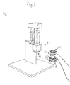
Fig. 1 shows, in a perspective view, an example of an embodiment of a 3D printer system according to the invention, wherein the first interconnection between the cartridge and the plunger assembly and the second interconnection between the cartridge and the printhead assembly are effective. -
Fig. 2 shows the situation ofFig. 1 again, however this time while a user is taking the mutually interconnected cartridge and printhead assembly out of the printer system, just after the user has disconnected the first interconnection between the cartridge and the plunger assembly. -
Fig. 3 separately shows, in a side view, the cartridge and printhead assembly of the previous figures again, however this time after the user has further disconnected the second interconnection between the cartridge and the printhead assembly. -
Fig. 4 shows, in a perspective view, the cartridge of the previous figures again, however, this time together with the abovementioned punch-fill adapter and the abovementioned handgrip adapter, these two adapters not yet being connected to the cartridge. -
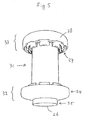
Fig. 5 shows, in a perspective view, the cartridge together with the punch-fill adapter and the handgrip adapter ofFig. 4 again, however this time when these two adapters are connected to the cartridge. -
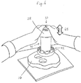
Fig. 6 shows, in a perspective view, the cartridge assembly ofFig. 5 again, however this time during punching, via the cutting edge of the punch-fill adapter, of slices out of a supply slice of a pasta dough, while the cartridge assembly is manually maneuvered via the handgrip area of the handgrip adapter. - The reference signs used in the abovementioned
Figs. 1-6 are referring to the abovementioned parts and aspects of the invention, as well as to related parts and aspects, in the following manner. - 1
- 3D printer system
- 2
- support structure
- 3
- cartridge assembly
- 4
- plunger assembly
- 5
- printhead assembly
- 6
- plunger actuating mechanism
- 7
- 3D movement mechanism
- 10
- plastic substance (pasta dough)
- 21
- first cartridge connector
- 22
- second cartridge connector
- 23
- circumferential wall
- 24
- punch-fill connector
- 25
- cutting ring
- 26
- circumferential cutting edge
- 27
- handgrip connector
- 28
- handgrip area
- 31
- cartridge
- 32
- punch-fill adapter
- 33
- handgrip adapter
- 41
- plunger assembly connector
- 51
- printhead assembly connector
- 52
- hot air inlet
- Reference is first made to the 3D printer system 1 of
Fig. 1 . This system 1 is for printing food, more particularly for printing fresh pasta dough in various predetermined 3D shapes. - In practice one places a food plate on the
support structure 2, below theprinthead assembly 5. Then, in the operation condition of the system 1, theplunger actuating mechanism 6 is actuating the plunger of theplunger assembly 4 to move within the cylindrical inner space of thecartridge 31 to thereby push the pasta dough successively out of thecartridge 31, through theprinthead assembly 5, out of theprinthead assembly 5, and onto the food plate, while at the same time the3D movement mechanism 7 is providing relative movement, according to a predetermined 3D movement trajectory, between thesupport structure 2, on the one hand, and theplunger assembly 4, thecartridge 31 and theprinthead assembly 5, on the other hand. - As to
Fig. 1 it is noted that, for reasons of simplicity, the3D movement mechanism 7 has been depicted in a highly schematical manner only. It is furthermore noted that, also for reasons of simplicity, the plunger of theplunger assembly 4 is not visible inFig. 1 . This plunger is located within the interior of theplunger assembly 4 to perform its vertical movements relative to thecartridge 31. Therein, a downward movement of the plunger within the inner space of thecartridge 31 evidently corresponds to pushing the pasta dough out of thecartridge 31 in the abovedescribed manner. Furthermore, as toFig. 1 , it is noted that thereference numeral 52 indicates a hot air inlet of theprinthead assembly 5. Thishot air inlet 52 may be used for hot air supply to quickly dry the pasta dough during the final stages of the pasta dough being processed and dispensed by theprinthead assembly 5. - When the pasta dough has been printed on the food plate in the predetermined 3D shape, e.g. the 3D shape of a nice flower or the like, the printed shape can then be placed in boiling water for a short time (e.g. one or two minutes), to get it ready for serving a dish.
- When the
cartridge 31 has to be refilled with new pasta dough, thecartridge 31 has to be removed from the 3D printer system 1 ofFig. 1 . This removal of thecartridge 31 is illustrated byFigs. 2 and3 .Fig. 2 shows that a user is taking the mutuallyinterconnected cartridge 31 andprinthead assembly 5 out of the printer system 1, just after the user has disconnected the first interconnection between thefirst cartridge connector 21 of thecartridge 31 and theplunger assembly connector 41 of theplunger assembly 4.Fig. 3 shows thecartridge 31 andprinthead assembly 5 again, however this time after the user has further disconnected the second interconnection between thesecond cartridge connector 22 ofcartridge 31 and theprinthead assembly connector 51 ofprinthead assembly 5. The disconnection action related to said second interconnection has been schematically illustrated by means of the shownarrow 61. It is noted that in the shown example said first interconnection and said second interconnection each are bayonet interconnections. -
Figs. 4 and5 show the manually releasable fourth interconnection between thesecond cartridge connector 22 of thecartridge 31 and the punch-fill connector 24 of the punch-fill adapter 32, as well as the manually releasable fifth interconnection between thefirst cartridge connector 21 of thecartridge 31 and thehandgrip connector 27 of thehandgrip adapter 33. It is seen that these fourth and fifth interconnections, just like said first and second interconnections, each are bayonet interconnections. The connection action related to said fifth interconnection has been schematically illustrated by means of the shownarrow 64 inFig. 4 . The connection actions related to said fourth interconnection have been schematically illustrated by means of the shownarrows Fig. 4 . It is seen that in the shown example the punch-fill adapter 32 consists of two separate parts, i.e. the punch-fill connector 24 and the cuttingring 25.Arrow 62 inFig. 4 illustrates the insertion of the cuttingring 25 into the punch-fill connector 24, whilearrow 63 inFig. 4 illustrates the connection action of the punch-fill connector 24, together with the inserted cuttingring 25, onto thesecond cartridge connector 22. It is noted that the punch-fill adapter does not necessarily have to be a two-part piece as illustrated. Alternatively, it may also be a one-part piece, or it may consist of more than two separate parts. -
Fig. 6 shows how by means of the punch-fill adapter slices can be punched out of a supply slice of apasta dough 10, while the cartridge assembly is manually maneuvered via thehandgrip area 28 of thehandgrip adapter 33. The downwardly directed part of the two-way arrow 65 inFig. 6 illustrates the downwardly directed punching movement. The upwardly directed part of the two-way arrow 65 inFig. 6 illustrates the upward movement after a punched slice has been taken into thecartridge 31. In the shown example, two punched slices have already been taken into thecartridge 31, while a third punched slice is underway. If, after some time, the supply slice ofdough 10 contains too many punched-out parts, it may be flattened again by means of dough rolling pin, while adding additional dough thereto, if desirable. - It is noted that in the present document the word "cylindrical", as used in the terms "cylindrical inner surface" and "cylindrical inner space" may for example refer to the shape of a circular cylinder, i.e. a cylinder having a circular base form. However, as used herein, the word "cylindrical" more generally refers to the broader mathematical definition of a cylinder, according to which broader definition a cylinder may have any arbitrary base form, such as an elliptical base form, a polygonal (e.g. square) base form, etcetera.
- While the invention has been described and illustrated in detail in the foregoing description and in the drawing figures, such description and illustration are to be considered exemplary and/or illustrative and not restrictive; the invention is not limited to the disclosed embodiments.
- For example, in the shown example, all of the described possible interconnections between a respective connector of the cartridge, on the one hand, and a corresponding connector of the plunger assembly, the printhead assembly, the punch-fill adapter, or the handgrip adapter, on the other hand, are bayonet interconnections. However, other than bayonet interconnections may be applied as well.
- Other variations to the disclosed embodiments can be understood and effected by those skilled in the art in practicing the claimed invention, from a study of the drawings, the disclosure, and the appended claims. In the claims, the word "comprising" does not exclude other elements or steps, and the indefinite article "a" or "an" does not exclude a plurality. A single other unit may fulfill the functions of several items recited in the claims. For the purpose of clarity and a concise description, features are disclosed herein as part of the same or separate embodiments, however, it will be appreciated that the scope of the invention may include embodiments having combinations of all or some of the features disclosed. Any reference signs in the claims should not be construed as limiting the scope.
Claims (4)
- A 3D printer system for printing a plastic substance (10), such as a dough, wherein the 3D printer system (1) comprises:- a support structure (2);- a cartridge assembly (3), comprising a refillable cartridge (31), which cartridge comprises a circumferential wall (23) having a cylindrical inner surface defining a cylindrical inner space of the cartridge for holding said plastic substance therein, said circumferential wall being provided with a first cartridge connector (21) and a second cartridge connector (22) at the two opposing longitudinal ends of the cartridge, respectively;- a plunger assembly (4), comprising a plunger and a plunger assembly connector (41), wherein the first cartridge connector and the plunger assembly connector are configured to cooperatively form a manually releasable first interconnection between the cartridge and the plunger assembly;- a printhead assembly (5), comprising a printhead assembly connector (51), wherein the second cartridge connector and the printhead assembly connector are configured to cooperatively form a manually releasable second interconnection between the cartridge and the printhead assembly;- a plunger actuating mechanism (6); and- a 3D movement mechanism (7);
and wherein the 3D printer system has an operation condition, in which:- said cylindrical inner space of the cartridge contains said plastic substance;- said first interconnection and said second interconnection are effective;- the plunger actuating mechanism is effective to actuate the plunger for movement within said cylindrical inner space to thereby push the plastic substance successively out of the cartridge, through the printhead assembly, and out of the printhead assembly; and- the 3D movement mechanism is effective to provide relative movement, according to predetermined 3D movement trajectories, between said support structure, on the one hand, and at least the plunger assembly, the cartridge and the printhead assembly, on the other hand;
characterized in that the cartridge assembly further comprises a punch-fill adapter (32) having a circumferential cutting edge (26) and being provided with a punch-fill connector (24), wherein:- the first cartridge connector and the punch-fill connector are configured to cooperatively form a manually releasable third interconnection between the cartridge and the punch-fill adapter, when said first interconnection is manually released; and/or- the second cartridge connector and the punch-fill connector are configured to cooperatively form a manually releasable fourth interconnection between the cartridge and the punch-fill adapter, when said second interconnection is manually released;
and wherein the cartridge assembly has a punch-fill condition, in which:- said third interconnection or said fourth interconnection is effective;- said said circumferential cutting edge is arranged in-line, as seen in longitudinal direction of the cartridge, with the cross-sectional circumferential geometry of the cylindrical inner surface of the circumferential wall of the cartridge; and- the cartridge assembly is effective as a manual tool for punching, by means of said circumferential cutting edge, punched slices out of a supply slice of said plastic substance, and thereby for automatically inserting said punched slices into the inner space of the cartridge. - A 3D printer system according to claim 1, wherein the cartridge assembly (3) further comprises a handgrip adapter (33) having a handgrip area 28 and being provided with a handgrip connector (27), wherein:- the first cartridge connector (21) and the handgrip connector are configured to cooperatively form a manually releasable fifth interconnection between the cartridge (31) and the handgrip adapter, when said first interconnection is manually released; and/or- the second cartridge connector (22) and the handgrip connector are configured to cooperatively form a manually releasable sixth interconnection between the cartridge and the handgrip adapter, when said second interconnection is manually released;
and wherein the cartridge assembly has a handgrip condition, in which:- said fifth interconnection or said sixth interconnection is effective; and- said handgrip area can manually be taken hold of during said punching. - A method for filling the cartridge (31) of the cartridge assembly (3) of a 3D printer system (1) according to claim 1 with a plastic substance (10), such as a dough, the method comprising the use of the cartridge assembly in its punch-fill condition as a manual tool for punching, by means of the circumferential cutting edge (26) of the punch-fill adapter (32) of the cartridge assembly, punched slices out of a supply slice of said plastic substance, and thereby for automatically inserting said punched slices into the inner space of the cartridge.
- A method according to claim 3, wherein the cartridge (31) is a cartridge of a 3D printer system (1) according to claim 2, and wherein, during said use of the cartridge assembly (3) in its punch-fill condition, the handgrip area (28) of the cartridge assembly is manually being taken hold of during said punching.
Priority Applications (5)
| Application Number | Priority Date | Filing Date | Title |
|---|---|---|---|
| EP15170963.1A EP3112132A1 (en) | 2015-06-08 | 2015-06-08 | 3d printer system and method for filling a cartridge of such a system |
| US15/578,768 US10609948B2 (en) | 2015-06-08 | 2016-06-06 | 3D printer system and method for filling a cartridge of such a system |
| JP2017563574A JP6773688B2 (en) | 2015-06-08 | 2016-06-06 | How to fill a 3D printing system and a cartridge for that system |
| EP16742028.0A EP3302940B1 (en) | 2015-06-08 | 2016-06-06 | 3d printer system and method for filling a cartridge of such a system |
| PCT/NL2016/050402 WO2016200254A1 (en) | 2015-06-08 | 2016-06-06 | 3d printer system and method for filling a cartridge of such a system |
Applications Claiming Priority (1)
| Application Number | Priority Date | Filing Date | Title |
|---|---|---|---|
| EP15170963.1A EP3112132A1 (en) | 2015-06-08 | 2015-06-08 | 3d printer system and method for filling a cartridge of such a system |
Publications (1)
| Publication Number | Publication Date |
|---|---|
| EP3112132A1 true EP3112132A1 (en) | 2017-01-04 |
Family
ID=53487181
Family Applications (2)
| Application Number | Title | Priority Date | Filing Date |
|---|---|---|---|
| EP15170963.1A Withdrawn EP3112132A1 (en) | 2015-06-08 | 2015-06-08 | 3d printer system and method for filling a cartridge of such a system |
| EP16742028.0A Active EP3302940B1 (en) | 2015-06-08 | 2016-06-06 | 3d printer system and method for filling a cartridge of such a system |
Family Applications After (1)
| Application Number | Title | Priority Date | Filing Date |
|---|---|---|---|
| EP16742028.0A Active EP3302940B1 (en) | 2015-06-08 | 2016-06-06 | 3d printer system and method for filling a cartridge of such a system |
Country Status (4)
| Country | Link |
|---|---|
| US (1) | US10609948B2 (en) |
| EP (2) | EP3112132A1 (en) |
| JP (1) | JP6773688B2 (en) |
| WO (1) | WO2016200254A1 (en) |
Cited By (1)
| Publication number | Priority date | Publication date | Assignee | Title |
|---|---|---|---|---|
| CN114889133A (en) * | 2022-04-22 | 2022-08-12 | 清华大学 | Multi-wheel drive synchronous belt wire feeding mechanism for FDM3D printing |
Families Citing this family (3)
| Publication number | Priority date | Publication date | Assignee | Title |
|---|---|---|---|---|
| CN108783559B (en) * | 2017-04-28 | 2021-02-09 | 鸿富锦精密工业(深圳)有限公司 | Material pipe exchange device of 3D printer |
| IT201800002656A1 (en) * | 2018-02-13 | 2019-08-13 | Barilla Flli G & R | Improved extrusion process and related device |
| CN110181814A (en) * | 2019-05-05 | 2019-08-30 | 厦门普瑞特科技有限公司 | A kind of fast disassembly type 3D printing head and printer |
Citations (2)
| Publication number | Priority date | Publication date | Assignee | Title |
|---|---|---|---|---|
| WO2012103005A2 (en) * | 2011-01-24 | 2012-08-02 | Cornell University | Deposition of materials for edible solid freeform fabrication |
| US20130089642A1 (en) * | 2004-08-11 | 2013-04-11 | Cornell University - Cornell Center For Technology Enterprise & Commercialization (Cctec) | Modular fabrication systems and methods |
Family Cites Families (7)
| Publication number | Priority date | Publication date | Assignee | Title |
|---|---|---|---|---|
| US3262404A (en) * | 1964-05-29 | 1966-07-26 | Mirro Aluminum Company | Cookie press |
| US3690805A (en) * | 1970-11-16 | 1972-09-12 | Baldwin Hamilton Co | Multiple fill compacting press |
| US6708853B1 (en) * | 2003-05-12 | 2004-03-23 | Wilton Industries, Inc. | Manual cookie press |
| US8506283B1 (en) * | 2012-03-06 | 2013-08-13 | Edward Ray Gonzales | Tamale maker |
| WO2015115897A1 (en) * | 2014-02-03 | 2015-08-06 | Nederlandse Organisatie Voor Toegepast-Natuurwetenschappelijk Onderzoek Tno | Method for the production of an edible object by powder bed (3d) printing and food products obtainable therewith |
| CN104336489A (en) * | 2014-11-20 | 2015-02-11 | 安徽省三车节能科技有限公司 | Method for producing space grid structural instant noodle cakes based on 3-dimensional (3D) print technology |
| CN104921291B (en) * | 2015-05-19 | 2017-01-18 | 湖北中烟工业有限责任公司 | Method for preparing medicine flavor cigarette from cigarette beads |
-
2015
- 2015-06-08 EP EP15170963.1A patent/EP3112132A1/en not_active Withdrawn
-
2016
- 2016-06-06 EP EP16742028.0A patent/EP3302940B1/en active Active
- 2016-06-06 WO PCT/NL2016/050402 patent/WO2016200254A1/en not_active Ceased
- 2016-06-06 JP JP2017563574A patent/JP6773688B2/en active Active
- 2016-06-06 US US15/578,768 patent/US10609948B2/en active Active
Patent Citations (2)
| Publication number | Priority date | Publication date | Assignee | Title |
|---|---|---|---|---|
| US20130089642A1 (en) * | 2004-08-11 | 2013-04-11 | Cornell University - Cornell Center For Technology Enterprise & Commercialization (Cctec) | Modular fabrication systems and methods |
| WO2012103005A2 (en) * | 2011-01-24 | 2012-08-02 | Cornell University | Deposition of materials for edible solid freeform fabrication |
Cited By (2)
| Publication number | Priority date | Publication date | Assignee | Title |
|---|---|---|---|---|
| CN114889133A (en) * | 2022-04-22 | 2022-08-12 | 清华大学 | Multi-wheel drive synchronous belt wire feeding mechanism for FDM3D printing |
| CN114889133B (en) * | 2022-04-22 | 2023-07-25 | 清华大学 | Multi-wheel driving synchronous belt wire feeding mechanism for FDM3D printing |
Also Published As
| Publication number | Publication date |
|---|---|
| EP3302940B1 (en) | 2019-05-29 |
| JP2018518395A (en) | 2018-07-12 |
| WO2016200254A1 (en) | 2016-12-15 |
| US20180168217A1 (en) | 2018-06-21 |
| US10609948B2 (en) | 2020-04-07 |
| JP6773688B2 (en) | 2020-10-21 |
| EP3302940A1 (en) | 2018-04-11 |
Similar Documents
| Publication | Publication Date | Title |
|---|---|---|
| EP3302940B1 (en) | 3d printer system and method for filling a cartridge of such a system | |
| GB2578026B (en) | Method for constructing GLRX1 gene knock-out animal model based on CRISPR/CAS9 | |
| US11013365B2 (en) | Cleaning arrangement for capsule based beverage dispensers | |
| WO2010095956A3 (en) | A cooking device and method of meal preparation | |
| JP6803016B2 (en) | Chicken bonjiri bone removal device | |
| US20130189410A1 (en) | Cupcake secret | |
| US20160015044A1 (en) | Whole cake cutting device | |
| JP2018518395A5 (en) | ||
| EP2590804B1 (en) | Sealing machine | |
| US20140220169A1 (en) | Pastry cutter | |
| US20150245727A1 (en) | Strawberry huller | |
| DK179244B1 (en) | VALVE ARRANGEMENTS FOR MINK BREEDING SYSTEMS | |
| EP3300867A1 (en) | Vegetable stick maker | |
| DE102011016708A1 (en) | Device for cutting foodstuff e.g. pizza, has cutting tool that is designed as thermal cutting tool, for cutting to-be-cut material | |
| KR20120102257A (en) | Dressed poultry cutting apparatus | |
| EP2117392B1 (en) | Batching device for pasty food products | |
| US20110123691A1 (en) | Method and Apparatus for Preparing Tamales | |
| ES2822675T3 (en) | An apparatus and method for forming a food product | |
| WO2012098366A1 (en) | Canned perishable product plug insert | |
| KR101338100B1 (en) | Tool for make cuts in the sausage | |
| WO2009021311A1 (en) | Device for partially sectioning baked products, method of using the same, and products made thereby | |
| JP6170011B2 (en) | Spoon for canning | |
| CN107597973A (en) | Prevent the diel that waste material is jumped out | |
| USD758124S1 (en) | Butter churn container | |
| Bidaurratzaga Aurre et al. | Are EU's economic partnership agreements developmental? |
Legal Events
| Date | Code | Title | Description |
|---|---|---|---|
| PUAI | Public reference made under article 153(3) epc to a published international application that has entered the european phase |
Free format text: ORIGINAL CODE: 0009012 |
|
| AK | Designated contracting states |
Kind code of ref document: A1 Designated state(s): AL AT BE BG CH CY CZ DE DK EE ES FI FR GB GR HR HU IE IS IT LI LT LU LV MC MK MT NL NO PL PT RO RS SE SI SK SM TR |
|
| AX | Request for extension of the european patent |
Extension state: BA ME |
|
| STAA | Information on the status of an ep patent application or granted ep patent |
Free format text: STATUS: THE APPLICATION IS DEEMED TO BE WITHDRAWN |
|
| 18D | Application deemed to be withdrawn |
Effective date: 20170705 |