EP3111971A1 - Suspension jig and method for transporting additive solution - Google Patents
Suspension jig and method for transporting additive solution Download PDFInfo
- Publication number
- EP3111971A1 EP3111971A1 EP15754993.2A EP15754993A EP3111971A1 EP 3111971 A1 EP3111971 A1 EP 3111971A1 EP 15754993 A EP15754993 A EP 15754993A EP 3111971 A1 EP3111971 A1 EP 3111971A1
- Authority
- EP
- European Patent Office
- Prior art keywords
- bag
- side tube
- hanging
- transfer line
- blood
- Prior art date
- Legal status (The legal status is an assumption and is not a legal conclusion. Google has not performed a legal analysis and makes no representation as to the accuracy of the status listed.)
- Granted
Links
Images





Classifications
-
- A—HUMAN NECESSITIES
- A61—MEDICAL OR VETERINARY SCIENCE; HYGIENE
- A61M—DEVICES FOR INTRODUCING MEDIA INTO, OR ONTO, THE BODY; DEVICES FOR TRANSDUCING BODY MEDIA OR FOR TAKING MEDIA FROM THE BODY; DEVICES FOR PRODUCING OR ENDING SLEEP OR STUPOR
- A61M1/00—Suction or pumping devices for medical purposes; Devices for carrying-off, for treatment of, or for carrying-over, body-liquids; Drainage systems
- A61M1/02—Blood transfusion apparatus
- A61M1/0272—Apparatus for treatment of blood or blood constituents prior to or for conservation, e.g. freezing, drying or centrifuging
- A61M1/0277—Frames constraining or supporting bags, e.g. during freezing
-
- A—HUMAN NECESSITIES
- A61—MEDICAL OR VETERINARY SCIENCE; HYGIENE
- A61J—CONTAINERS SPECIALLY ADAPTED FOR MEDICAL OR PHARMACEUTICAL PURPOSES; DEVICES OR METHODS SPECIALLY ADAPTED FOR BRINGING PHARMACEUTICAL PRODUCTS INTO PARTICULAR PHYSICAL OR ADMINISTERING FORMS; DEVICES FOR ADMINISTERING FOOD OR MEDICINES ORALLY; BABY COMFORTERS; DEVICES FOR RECEIVING SPITTLE
- A61J1/00—Containers specially adapted for medical or pharmaceutical purposes
- A61J1/14—Details; Accessories therefor
- A61J1/16—Holders for containers
-
- A—HUMAN NECESSITIES
- A61—MEDICAL OR VETERINARY SCIENCE; HYGIENE
- A61M—DEVICES FOR INTRODUCING MEDIA INTO, OR ONTO, THE BODY; DEVICES FOR TRANSDUCING BODY MEDIA OR FOR TAKING MEDIA FROM THE BODY; DEVICES FOR PRODUCING OR ENDING SLEEP OR STUPOR
- A61M1/00—Suction or pumping devices for medical purposes; Devices for carrying-off, for treatment of, or for carrying-over, body-liquids; Drainage systems
- A61M1/02—Blood transfusion apparatus
- A61M1/0209—Multiple bag systems for separating or storing blood components
-
- A—HUMAN NECESSITIES
- A61—MEDICAL OR VETERINARY SCIENCE; HYGIENE
- A61M—DEVICES FOR INTRODUCING MEDIA INTO, OR ONTO, THE BODY; DEVICES FOR TRANSDUCING BODY MEDIA OR FOR TAKING MEDIA FROM THE BODY; DEVICES FOR PRODUCING OR ENDING SLEEP OR STUPOR
- A61M1/00—Suction or pumping devices for medical purposes; Devices for carrying-off, for treatment of, or for carrying-over, body-liquids; Drainage systems
- A61M1/02—Blood transfusion apparatus
- A61M1/0209—Multiple bag systems for separating or storing blood components
- A61M1/0218—Multiple bag systems for separating or storing blood components with filters
-
- A—HUMAN NECESSITIES
- A61—MEDICAL OR VETERINARY SCIENCE; HYGIENE
- A61M—DEVICES FOR INTRODUCING MEDIA INTO, OR ONTO, THE BODY; DEVICES FOR TRANSDUCING BODY MEDIA OR FOR TAKING MEDIA FROM THE BODY; DEVICES FOR PRODUCING OR ENDING SLEEP OR STUPOR
- A61M1/00—Suction or pumping devices for medical purposes; Devices for carrying-off, for treatment of, or for carrying-over, body-liquids; Drainage systems
- A61M1/36—Other treatment of blood in a by-pass of the natural circulatory system, e.g. temperature adaptation, irradiation ; Extra-corporeal blood circuits
- A61M1/3693—Other treatment of blood in a by-pass of the natural circulatory system, e.g. temperature adaptation, irradiation ; Extra-corporeal blood circuits using separation based on different densities of components, e.g. centrifuging
-
- A—HUMAN NECESSITIES
- A61—MEDICAL OR VETERINARY SCIENCE; HYGIENE
- A61M—DEVICES FOR INTRODUCING MEDIA INTO, OR ONTO, THE BODY; DEVICES FOR TRANSDUCING BODY MEDIA OR FOR TAKING MEDIA FROM THE BODY; DEVICES FOR PRODUCING OR ENDING SLEEP OR STUPOR
- A61M1/00—Suction or pumping devices for medical purposes; Devices for carrying-off, for treatment of, or for carrying-over, body-liquids; Drainage systems
- A61M1/36—Other treatment of blood in a by-pass of the natural circulatory system, e.g. temperature adaptation, irradiation ; Extra-corporeal blood circuits
- A61M1/3693—Other treatment of blood in a by-pass of the natural circulatory system, e.g. temperature adaptation, irradiation ; Extra-corporeal blood circuits using separation based on different densities of components, e.g. centrifuging
- A61M1/3696—Other treatment of blood in a by-pass of the natural circulatory system, e.g. temperature adaptation, irradiation ; Extra-corporeal blood circuits using separation based on different densities of components, e.g. centrifuging with means for adding or withdrawing liquid substances during the centrifugation, e.g. continuous centrifugation
-
- A—HUMAN NECESSITIES
- A61—MEDICAL OR VETERINARY SCIENCE; HYGIENE
- A61M—DEVICES FOR INTRODUCING MEDIA INTO, OR ONTO, THE BODY; DEVICES FOR TRANSDUCING BODY MEDIA OR FOR TAKING MEDIA FROM THE BODY; DEVICES FOR PRODUCING OR ENDING SLEEP OR STUPOR
- A61M2202/00—Special media to be introduced, removed or treated
- A61M2202/04—Liquids
- A61M2202/0413—Blood
- A61M2202/0439—White blood cells; Leucocytes
-
- A—HUMAN NECESSITIES
- A61—MEDICAL OR VETERINARY SCIENCE; HYGIENE
- A61M—DEVICES FOR INTRODUCING MEDIA INTO, OR ONTO, THE BODY; DEVICES FOR TRANSDUCING BODY MEDIA OR FOR TAKING MEDIA FROM THE BODY; DEVICES FOR PRODUCING OR ENDING SLEEP OR STUPOR
- A61M2209/00—Ancillary equipment
- A61M2209/08—Supports for equipment
- A61M2209/082—Mounting brackets, arm supports for equipment
Definitions
- the present invention relates to a hanging device and an additive solution transfer method for a blood bag system.
- Transfusion conducted in recent years includes component transfusion, in which a component is separated from blood (whole blood) obtained by blood donation, or the like, and solely a We component required by a patient is supplied.
- component transfusion it is possible to reduce the burden and side effects on a circulatory system of the patient and to effectively use the donated blood.
- the blood (whole blood) obtained by blood donation or a blood component prepared from the whole blood is separated through centrifugation into a plurality of layers inside a blood bag.
- residual components white-cell-poor platelet-poor blood
- red blood cells concentrated red blood cells
- the components are initially separated into a plasma layer as a supernatant component and red blood cells (concentrated red blood cells) layer as a sedimentary component by centrifugation (centrifugation step).
- the plasma is transferred to a plasma bag via a tube connected to the blood bag, so as to leave concentrated red blood cells in the blood bag (separation-transfer step).
- a red blood cell preservation liquid is added to the concentrated red blood cells by transferring, via a tube, the red blood cell preservation liquid stored in a medical fluid bag into the blood bag (addition step).
- the present invention provides a hanging device configured to hang a blood bag system including: a first bag containing a blood component; a second bag containing additive solution; and a transfer line that forms a flow path between the first bag and the second bag, the hanging device including: a second bag hanging section configured to hang the second bag such that a influx portion of the second bag faces downward; and support mechanisms configured to support the first bag or the transfer line in a predetermined state such that, when the additive solution is transferred from the second bag to the first bag using a height difference between the first bag and the second bag, air from the second bag stops in the middle of the flow path.
- the hanging device configured as above, when the additive solution is transferred from the second bag to the first bag using the height difference between the first bag and the second bag soasto add the additive solution to the blood component in the first bag, the air from the second bag stops in the middle of the transfer line. With this configuration, it is possible to prevent the air from the second bag from mixing into the first bag. Accordingly, after the additive solution is added to the blood component in the first bag, the amount of air in the first bag is the amount that scarcely needs air bleeding operation. As a result, it is possible to eliminate air bleeding operation after addition of the additive solution.
- the above-described hanging device may also be configured such that the support mechanism hangs the first bag to arrange the influx portion of the first bag to face downward at a position lower than the second bag hung by the second bag hanging section.
- the support mechanism hangs the first bag to arrange the influx portion of the first bag to face downward at a position lower than the second bag hung by the second bag hanging section.
- the above-described hanging device may be configured such that the transfer line includes a first bag-side tube formed of a flexible material connected to the first bag, a second bag-side tube formed of a flexible material connected to the second bag, and a branch section formed to be harder than the first bag-side tube and the second bag-side tube and provided between the first bag-side tube and the second bag-side tube, and such that the support mechanism arranges the liquid level inside the first bag to come at a position lower than the branch section.
- the above-described hanging device may be also configured such that the support mechanism supports the first bag and the transfer line so as to form, in the transfer line, a high-level site existing at a position higher than the liquid level inside the first bag, and a low-level site existing at a position lower than the high-level site on both sides of the flow path of the high-level site.
- the above-described hanging device may be configured such that the transfer line includes a first bag-side tube formed of a flexible material, connected to the first bag, a second bag-side tube formed of a flexible material connected to the second bag, and a branch section formed to be harder than the first bag-side tube and the second bag-side tube and provided between the first bag-side tube and the second bag-side tube, and such that the support mechanism arranges the high-level site to come at a position lower than the branch section.
- the present invention according to the method for transferring the additive solution is targeted at a blood bag system including a first bag containing a blood component, a second bag containing additive solution, and a delivery line that forms a flow path between the first bag and the second bag, the method being configured to transfer the additive solution from the second bag to the first bag, the method for transferring the additive solution including: a support step of supporting the first bag or the transfer line in a predetermined state such that, when the additive solution is transferred from the second bag to the first bag using a height difference between the first bag and the second bag, air from the second bag stops in the middle of the flow path; and a hanging step of hanging the second bag such that a influx portion of the second bag faces downward.
- the above-described method for transferring the additive solution may also be configured such that the support step hangs the first bag such that the influx portion of the first bag faces downward at a position lower than the second bag hung at the support step.
- the above-described method for transferring the additive solution may also be configured such that the support step supports the first bag diagonally with respect to the horizontal direction, to arrange the first bag to be gradually lowered toward the influx portion of the first bag, at a position lower than the second bag to be hung.
- the above-described method for transferring the additive solution may be configured such that the transfer line includes a first bag-side tube formed of a flexible material connected to the first bag, a second bag-side tube formed of a flexible material connected to the second bag, and a branch section formed to be harder than the first bag-side tube and the second bag-side tube and provided between the first bag-side tube and the second bag-side tube, and such that the support step arranges the liquid level inside the first bag to come at a position lower than the branch section.
- the above-described method for transferring the additive solution may be also configured such that the support step supports the first bag and the transfer line so as to form, in the transfer line, a high-level site existing at a position higher than the liquid level inside the first bag, and a low-level site existing at a position lower than the high-level site on both sides of the flow path of the high-level site.
- the above-described method for transferring the additive solution may be configured such that the transfer line includes a first bag-side tube formed of a flexible material connected to the first bag, a second bag-side tube formed of a flexible material connected to the second bag, and a branch section formed to be harder than the first bag-side tube and the second bag-side tube and provided between the first bag-side tube and the second bag-side tube, and such that the support step arranges the high-level site to come at a position lower than the branch section.
- the blood component may be a concentrated red blood cell and the additive solution may be a red blood cell preservation.
- the blood component may be a concentrated red blood cell and the additive solution may be a red blood cell preservation.
- the hanging device and the method for transferring the additive solution according to the present invention it is possible to efficiently produce blood products at a production process of the blood products by eliminating the need for manual air bleeding operation after addition of the additive solution.
- the blood bag system 10 is intended to centrifuge blood containing a plurality of components into a plurality of components having a different specific gravity (for example, two components including a relatively low specific gravity component and a relatively high specific gravity component) and to store and preserve the components separately in different bags.
- a different specific gravity for example, two components including a relatively low specific gravity component and a relatively high specific gravity component
- the blood bag system 10 is configured to centrifuge a residual blood component obtained by removing white blood cells and platelets from whole blood into two components, namely, plasma and concentrated red blood cells, and to store and preserve the plasma and the concentrated red blood cells separately in different bags.
- the hanging devices 100A to 100C illustrated in Figs. 5 to 8 are used to hang a portion of the blood bag system 10 (separation processing unit 16 to be described below).
- the blood bag system 10 includes a blood collection unit 12, a preprocessing unit 14, and a separation processing unit 16.
- the blood collection unit 12 collects blood (whole blood) from a donor.
- the preprocessing unit 14 removes a predetermined blood component from the whole blood.
- the separation processing unit 16 centrifuges the residual blood component obtained by removing the predetermined component into a plurality of blood components and stores (pools) the individual blood components in different bags.
- the blood collection unit 12 will first be described.
- the blood collection unit 12 includes a blood collection bag 18, blood collection tubes 20 and 22, a blood collection needle 24, a branching connector 26, and an initial flow blood bag 28.
- the blood collection bag 18 is a bag for storing (pooling) blood (whole blood) collected from a donor.
- an anticoagulant is placed in the blood collection bag 18 in advance.
- the anticoagulant is typically a liquid and may include, for example, an ACD-A solution, a CPD solution, a CPDA-1 solution, a heparin sodium solution, or the like.
- the amount of the anticoagulant is appropriately determined depending on the amount of blood to be collected.
- the blood collection bag 18 is formed in a bag shape by overlapping flexible sheet materials formed of flexible resin such as polyvinyl chloride or polyolefin on each other and by fusion bonding (through thermal fusion bonding or high-frequency welding) or gluing on peripheral sealing portions of the sheet materials to each other.
- the initial flow blood bag 28 is also formed in a bag shape.
- One end of the proximal-side blood collection tube 20 is connected to the blood collection bag 18.
- a clamp 30 for closing or opening a flow path in the blood collection tube 20 is provided in the middle of the blood collection tube 20.
- One end of a frangible part 32 is connected to the other end of the blood collection tube 20.
- the frangible part 32 is configured such that the flow path is closed in an initial state and is then opened by performing breaking operation.
- a first port 26a of the branching connector 26 is connected to the other end of the frangible part 32.
- One end of the distal-side blood collection tube 22 is connected to a second port 26b of the branching connector 26, and the blood collection needle 24 is connected to the other end of the blood collection tube 22.
- a cap 24a is attached to the blood collection needle 24 before use, and a needle guard 24b is attached to the blood collection needle 24 after use.
- the needle guard 24b is movably arranged along the longitudinal direction of the blood collection tube 22.
- branching tube 34 One end of a branching tube 34 is connected to a third port 26c of the branching connector 26.
- a clamp 36 that closes or opens a flow path of the branching tube 34 is provided in the middle of the branching tube 34.
- the initial flow blood bag 28 is connected to the other end of the branching tube 34.
- a sampling port 38 is connected to the initial flow blood bag 28.
- the direction and arrangement of the branching connector 26 are not limited to the configuration illustrated in Fig. 1 but may be appropriately changed.
- the preprocessing unit 14 includes a filter 40, an inlet-side tube 42, and an outlet-side tube 44.
- the filter 40 removes predetermined cells.
- the inlet-side tube 42 is connected at its one end to the blood collection bag 18 and connected at its other end to an inlet of the filter 40.
- the outlet-side tube 44 is connected at its one end to an outlet of the filter 40 and connected at its other end to the separation processing unit 16.
- the filter 40 is configured as a white blood cell removing filter.
- the white blood cell removing filter it is appropriate to use a filter having a structure that stores a liquid-passing porous body having numerous micropores communicating from one side surface to the other side surface thereof in a bag-shaped housing formed of a flexible resin sheet.
- the filter 40 is configured to be able to supplement platelets, as well.
- the inlet-side tube 42 is a tube for transferreing the blood collected from a donor from the blood collection bag 18 to the filter 40, and is connected to a top portion of the blood collection bag 18.
- a frangible part 46 is provided at a blood collection bag 18-side end of the inlet-side tube 42.
- the frangible part 46 has the same configuration and function as those of the frangible part 32 described above.
- the outlet-side tube 44 is a tube for transferreing the residual blood components obtained by removing predetermined cells (in the present embodiment, white blood cells and platelets) using the filter 40, to the separation processing unit 16 (specifically, a primary bag 50 described below).
- a clamp 48 that closes and opens a flow path of the outlet-side tube 44 is provided in the middle of the outlet-side tube 44.
- a clamp similar to the clamp 30 described above may be employed as the clamp 48.
- the separation processing unit 16 includes a primary bag (first bag) 50, a subsidiary bag (third bag) 52, a medical fluid bag (second bag) 54, and a transfer line 55.
- the primary bag (first bag) 50 stores (pools) the residual blood component obtained by removing the predetermined cells using the filter 40.
- the subsidiary bag (third bag) 52 stores and preserves a supernatant component obtained by centrifuging the blood component inside the primary bag 50.
- the medical fluid bag (second bag) 54 stores a red blood cell preservation M (additive solution).
- the transfer line 55 is connected to the primary bag 50, the subsidiary bag 52, and the medical fluid bag 54.
- the primary bag 50, the subsidiary bag 52 and the medical fluid bag 54 are each formed in a bag shape by overlapping flexible sheet materials formed of flexible resin such as polyvinyl chloride or polyolefin on each other and by fusion bonding (through thermal fusion bonding or high-frequency welding) or gluing on peripheral sealing portions of the sheet materials to each other.
- Slits 63 to 65 are provided on bottom portions of the primary bag 50, the subsidiary bag 52, and the medical fluid bag 54 so as to enable hanging each of the bags with their top portions facing downward.
- the primary bag 50 serves as both a bag for storing (pooling) the residual blood component obtained by removing the predetermined cells using the filter 40 and a bag for preserving a sedimentary component (concentrated red blood cells) obtained by centrifuging the blood component.
- the transfer line 55 is a means to connect the primary bag 50 with the subsidiary bag 52 and to connect the primary bag 50 with the medical fluid bag 54.
- the transfer line 55 includes a first tube 56 (first bag-side tube) connected to the primary bag 50, a second tube 58 connected to the subsidiary bag 52, a third tube 60 (second bag-side tube) connected to the medical fluid bag 54, and a branching connector 62 (branch section) connected to the first to third tubes 56, 58, and 60.
- a breakable frangible part 66 is provided at one end (primary bag 50-side end) of the first tube 56 to prevent the blood component inside the primary bag 50 from being transferred to other bags until the breaking operation is performed.
- the frangible part 66 has the same configuration and functionality as those of the frangible part 32 described above.
- the other end of the first tube 56 is connected to the first port 62a of the branching connector 62.
- One end of the second tube 58 is connected to the secondport 62b of the branching connector 62.
- One end of the third tube 60 is connected to the third port 62c of the branching connector 62.
- the branching connector 62 is formed of a material harder than the material of the first to third tubes 56, 58, and 60.
- a MAP solution As the red blood cell preservation M contained in the medical fluid bag 54, a MAP solution, an SAGM solution, OPTISOL, or the like, may be employed.
- a breakable frangible part 68 is provided at the medical fluid bag 54-side end of the third tube 60 to prevent the red blood cell preservation liquid M in the medical fluid bag 54 from being transferred to other bags.
- the frangible part 68 has the same configuration and functionality as those of the frangible part 32 described above.
- the tubes in the blood bag system 10 are formed of transparent flexible resin.
- the clamps 30, 36 and 48 may be standard products that have been conventionally used.
- the clamps 30, 36, and 48 are preferably classified by different colors depending on a place or purpose of use.
- the clamps 30, 36, and 48 are in open states, so that the bags internally communicate with each other to maintain a uniformly sterilized state.
- the blood bag system 10 may be, for example, attached to a centrifugation and separation apparatus 70 illustrated in Fig. 2 in use.
- the centrifugation and separation apparatus 70 is used to centrifuge the blood component stored inside the primary bag 50 into two layers, namely, a plasma layer and a concentrated red blood cell layer, and deliver the plasma into the subsidiary bag 52 while keeping the concentrated red blood cells to remain inside the primary bag 50.
- the centrifugation and separation apparatus 70 has a box shape and includes a main body 71, a lid 72, a centrifugal drum 74, six unit insertion holes 76, six insert units 78, and six pressers 80 (refer to Fig. 3 , etc.).
- the lid 72 is openable and closable on an upper surface.
- the centrifugal drum 74 is internally installed.
- the six unit insertion holes 76 are arranged inside the centrifugal drum 74 at a regular angular interval (60°).
- the six insert units 78 are insertable and removable respectively into/from the unit insertion holes 76.
- the six pressers 80 provided at a center, and are capable of advancing and retreating in a rotational radial direction with respect to each of the insert units 78.
- the centrifugation and separation apparatus 70 is operated based on operation of an operation unit 82 provided in front and is controlled by a microcomputer (not illustrated).
- insert units 78 are attached to the centrifugation and separation apparatus 70.
- the outlet-side tube 44 is fusion-bonded to prevent leakage using a tube sealer, or the like, and is then cut. Accordingly, among the blood bag system 10, merely the separation processing unit 16 and a portion of the outlet-side tube 44 are attached to the insert unit 78.
- Processing including collecting blood from a donor using the blood bag system 10 illustrated in Fig. 1 , removing white blood cells and platelets from collected blood, separating residual components into two layers of plasma and concentrated red blood cells, and then pooling the separated components in the separate bags can be performed by the following procedure, for example.
- blood collection step is performed such that the skin of a donor is punctured and the blood is collected from the donor.
- a predetermined amount of initial flow of the blood (initial-flow-at-blood-collection) collected from a donor is stored in the initial flow blood bag 28 before the blood is collected into the blood collection bag 18.
- the clamp 36 is set to an open state while the frangible part 32 is kept to a closed state (initial state).
- initial-flow-at-blood-collection is collected into the blood sampling tube.
- the initial-flow-at-blood-collection is used as blood sample for testing. Portions from the branching connector 26 to the sampling port 38 may be omitted depending on application.
- the branching tube 34 is closed by the clamp 36, and breaking operation is performed for the frangible part 32 to open the flow path of the blood collection tube 20.
- the clamp 30 is set to an open state, the blood from the donor flows sequentially through the blood collection tubes 22 and 20 into the blood collection bag 18.
- the blood collection tube 20 is closed by the clamp 30 so as not to let the blood in the blood collection bag 18 flow out. After the blood collection tube 20 is fusion-bonded and sealed by a tube sealer, or the like, the blood collection tube 20 is then cut at the sealed portion.
- the filter 40 is arranged in an intermediate position. Thereafter, breaking operation is performed on the frangible part 46 provided at one end portion of the inlet-side tube 42 to open the flow path of the inlet-side tube 42.
- breaking operation is performed on the frangible part 46 provided at one end portion of the inlet-side tube 42 to open the flow path of the inlet-side tube 42.
- the whole blood in the blood collection bag 18 flows through the inlet-side tube 42 into the filter 40, and with white blood cells and platelets removed in the course of passing through the filter 40, flows through the outlet-side tube 44 into the primary bag 50 to be collected therein.
- the primary bag 50 not only the blood from which white blood cells and platelets have been removed but also air existing in the filter 40 flows into the primary bag 50.
- outlet-side tube 44 is fusion-bonded and sealed at a position downstream of the clamp 48 using a tube sealer, or the like, and the outlet-side tube 44 is cut at the sealed portion.
- the separation processing unit 16 of the blood bag system 10 is attached to the centrifugation and separation apparatus 70.
- the above-described breaking operation is performed on the frangible part 66 so as to open the flow path of the frangible part 66.
- the breaking operation of the frangible part 66 may be performed before or after attaching the primary bag 50 to the centrifugation and separation apparatus 70.
- the blood bag system 10 (specifically, separation processing unit 16) is attached to the insert unit 78, and the insert unit 78 is then inserted into the unit insertion hole 76 to achieve the state of the schematic diagram illustrated in Fig. 3 .
- the directions A indicated by the double arrow represent radial directions of the centrifugal drum 74 of the centrifugation and separation apparatus 70. More specifically, the direction A1 represents an inward radial direction and the direction A2 represents an outward radial direction.
- the primary bag 50 while being attached to the insert unit 78, is held vertically (extending in an up-down direction), and stored in the centrifugation and separation apparatus 70 such that the thickness direction of the bag main body is arranged in the directions A.
- centrifugal force is applied to the primary bag 50 in the A2 direction.
- the centrifugation and separation apparatus 70 includes a sensor 90 that detects the type of liquid passing through the first tube 56.
- the sensor 90 includes, for example, a light-transmitting section and a light-receiving section and can determine the type of the liquid passing there between based on a light transmission level of the liquid.
- the centrifugation and separation apparatus 70 further includes a clamp 92 and a clamp 94.
- the clamp 92 is operable to open and close and switches open/close of the flow path of the second tube 58 by open/close operation.
- the clamp 94 is operable to open and close and switches open/close of the flow path of the third tube 60 by open/close operation.
- clamps 92 and 94 are attached to the second tube 58 and the third tube 60 respectively beforehand and that an operation mechanism to open and close the clamps 92 and 94 is provided in the centrifugation and separation apparatus 70.
- the lid 72 of the centrifugation and separation apparatus 70 is closed, and thereafter, the centrifugation step and the separation-transfer step are automatically performed by operating the operation unit 82.
- the clamps 92 and 94 are closed before the centrifugation step is started. Accordingly, flow paths of the second and third tubes 58 and 60 are closed. Air exists in a top portion inside the primary bag 50. This air is the air that existed in the filter 40 and flew into the primary bag 50 when blood filtration is performed by the filter 40.
- the centrifugation step is performed by rotating the centrifugal drum 74, that is, the blood component pooled in the primary bag 50 is separated into plasma and concentrated red blood cells.
- the blood component pooled in the primary bag 50 receives a centrifugal force.
- the concentrated red blood cells as a high specific gravity component are moved in the outward radial direction (direction A2), whereas the plasma as a low specific gravity component is moved in the inward radial direction (direction A1), and thus, the blood component is separated into two layers.
- the centrifugation and separation apparatus 70 performs an air separation step after the centrifugation step.
- the clamp 94 is opened while the rotation of centrifugal drum 74 is maintained, thereby switching the flow path of the third tube 60 to an open state.
- the primarybag 50 is pressed by displacing the presser 80 in the outward radial direction (direction A2). Since the volume of the primary bag 50 is reduced because it is clamped between the presser 80 and the wall, air is discharged from inside the primary bag 50. Accordingly, the air is flown into the medical fluid bag 54 via the first tube 56, the branching connector 62, and the third tube 60.
- the centrifugation and separation apparatus 70 performs plasma separation and separation step after the air separation step. Specifically, after the air has flown out of the primary bag 50, since the first tube 56 is directed toward the inner diameter side, the plasma located in the innermost diameter side starts to flow out of the primary bag 50. At this time, when the flow of the plasma into the first tube 56 is detected by the sensor 90, the third tube 60 is switched to a closed state by closing the clamp 94 while maintaining the rotation of the centrifugal drum 74, and together with this, the second tube 58 is switched to an open state by opening the clamp 92. This allows the plasma that has flown out of the primary bag 50 to flow into the subsidiarybag 52 via the first tube 56, the branching connector 62, and the second tube 58.
- the concentrated red blood cells start to flow out of the primary bag 50.
- the presser 80 is stopped, and the flow path of the second tube 58 is closed by closing the clamp 92. Accordingly, it is possible to block the entry of flow of the red blood cells into the subsidiary bag 52.
- the separation processing unit 16 is taken out of the insert unit 78 and the second tube 58 is fusion-bonded and sealed by a tube sealer, or the like, and thereafter, is cut, thereby separating the subsidiary bag 52.
- Welding, sealing and cutting of the second tube 58 using the tube sealer, or the like, may also be performed within the centrifugation and separation apparatus 70 using mechanical operation, by adding a tube-sealing function, cutting function, or the like, to the clamp 92.
- the addition step is performed manually.
- the red blood cell preservation liquid M is added to the concentrated redblood cells.
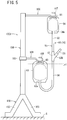
- the addition step can be performed, for example, by using the hanging device 100A according to the first embodiment, illustrated in Fig. 5 .
- the hanging device 100A is used when the red blood cell preservation liquid M is transferred from the medical fluid bag 54 to the primary bag 50 using the height difference between the primary bag 50 and the medical fluid bag 54, in order to add the red blood cell preservation liquid M to the concentrated red blood cells inside the primary bag 50.
- the hanging device 100A includes a base 102, a support column 104, and two hanging sections 106 and 108 (second bag hanging section, support mechanism).
- the base 102 is placed on an installation surface S.
- the support column 104 is supported by the base 102 and extends in the up-down direction.
- the hanging sections 106 and 108 are supported by the support column 104 with an interval in the up-down direction.
- the base 102 has a plurality of legs 103 in an exemplary illustration. The form, however, is not limited to this, but may have a plate shape expanding in the horizontal direction.
- the hanging section 106 provided relatively at an upper side (hereinafter, referred to as an "upper hanging section 106") is configured to be able to hang the medical fluid bag 54 such that a influx portion 54a of the medical fluid bag 54 faces downward (namely, upside down).
- the upper hanging section 106 is formed into a stick-like shape protruding in a direction (horizontal direction in the exemplary illustration) crossing the support column 104.
- a curved hook section 107 is provided at a free end-side of the upper hanging section 106. By inserting the hook section 107 into the slit 65 provided on a bottom portion of the medical fluid bag 54, it is possible to hang the medical fluid bag 54 upside down.
- the hanging section 108 provided relatively at lower side (hereinafter, referred to as an "lower hanging section 108") is configured to be able to hang the primary bag 50 such that a influx portion 50a of the primary bag 50 faces downward (namely, upside down) at a position lower than the medical fluid bag 54 hung by the upper hanging section 106.
- the lower hanging section 108 is formed into a stick-like shape protruding in a direction (horizontal direction in the exemplary illustration) crossing the support column 104.
- a curved hook section 109 is provided at a free end-side of the lower hanging section 108.
- the lower hanging section 108 configured in this manner functions as a support mechanism to support the primary bag 50 in a predetermined state such that, when the red blood cell preservation liquid M is transferred from the medical fluid bag 54 to the primary bag 50 using the height difference between the primary bag 50 and the medical fluid bag 54, air from the medical fluid bag 54 stops in the middle of the transfer line 55.
- the upper hanging section 106 and the lower hanging section 108 have difference lengths.
- the lengths, however, may be the same.
- the hanging device 100A may further include a height adjustment mechanism 110 for adjusting the hanging height when hung by the lower hanging section 108.
- the height adjustment mechanism 110 is slidable in the up-down direction with respect to the support column 104 and can hold an adjusted height position.
- it is allowable to employ a configuration that can adjust the hanging height using the lower hanging section 108 that can change its angle with respect to the support column 104.
- the blood bag system 10 (separation processing unit 16) is set on the hanging device 100A as illustrated in Fig. 5 .
- the primary bag 50 is hung by hooking the primary bag 50 at a position of the slit 63 onto a hook section 109 of the lower hanging section 108 such that the influx portion 50a of the primary bag 50 faces downward.
- the medical fluid bag 54 is hung by hooking the medical fluid bag 54 at a position of the slit 65 onto the hook section 107 of the upper hanging section 106 such that the influx portion 54a of the medical fluid bag 54 faces downward.
- a liquid level Lv1 inside the primary bag 50 is at a position lower than the branching connector 62, as illustrated in Fig. 5 .
- the hanging height of the primary bag 50 is adjustable with the height adjustment mechanism 110, and thus, it is possible to easily set the liquid level Lv1 inside the primary bag 50 to a position lower than the branching connector 62.
- the position of the lower hanging section 108 has been set beforehand such that the liquid level Lv1 inside the primary bag 50 comes at a position lower than the branching connector 62 with the medical fluid bag 54 and the primary bag 50 being respectively hung on the upper hanging section 106 and the lower hanging section 108.
- the redblood cell preservation liquid M inside the medical fluid bag 54 starts to move downward by gravity due to the height difference between the medical fluid bag 54 and the primary bag 50.
- air exists in a top portion inside the medical fluid bag 54, namely, in a portion above the red blood cell preservation liquid M.
- the third tube 60 includes air inside itself and this air flows into the primary bag 50 at an initial stage of the addition step. Fortunately, however, the amount of air inside the third tube 60 is significantly less than the amount of air inside the medical fluid bag 54, and thus, the amount of air flowing into the primary bag 50 at the addition step would be small. Accordingly, after completion of the addition step, the amount of air inside the primary bag 50 is the amount that scarcely needs air bleeding operation.
- the air from the medical fluid bag 54 stops in the middle of the transfer line 55 when the red blood cell preservation liquid M is transferred from the medical fluid bag 54 to the primary bag 50 using the height difference between the primary bag 50 and the medical fluid bag 54 in order to add the red blood cell preservation liquid M to the concentrated red blood cells inside the primary bag 50.
- This can prevent the air from the medical fluid bag 54 from mixing into the primary bag 50. Accordingly, after the red blood cell preservation liquid M has been added to the concentrated red blood cells, the amount of air inside the primary bag 50 is the amount that scarcely needs air bleeding operation. As a result, it is possible to eliminate air bleeding operation after addition of the red blood cell preservation liquid M.
- the liquid level Lv1 inside the primary bag 50 comes at a position higher than the influx portion 50a of the primary bag 50 when the additive solution is transferred from the medical fluidbag54 to the primary bag 50. Accordingly, the air moving inside the transfer line 55 from the medical fluid bag 54 stops at a position of the liquid level Lv1 inside the primary bag 50. As a result, it is possible, with a simple configuration, to appropriately prevent the air from the medical fluid bag 54 from mixing into the primary bag 50.
- the above-described hanging device 100A is configured to arrange both the upper hanging section 106 and the lower hanging section 108 to be on the same stand (base 102 and support column 104).
- the upper hanging section 106 and the lower hanging section 108 may be provided on separate stands or constructions.
- the primary bag 50 may be hung upside down by hanging the primary bag 50 at the slit 63 on a second port 62b of the branching connector 62 instead of hanging the primary bag 50 upside down on the lower hanging section 108.
- the air moving inside the transfer line 55 from the medical fluid bag 54 stops at a level corresponding to a liquid level Lv1 inside the primary bag 50. Accordingly, similarly to the addition step in Fig. 5 , it is possible to appropriately prevent the air from the medical fluid bag 54 from mixing into the primary bag 50.
- a protruding portion e.g., another port
- the lower hanging section 108 can be omitted.
- the above-described addition step can be performed by using a hanging device 100B according to a second embodiment illustrated in Fig. 6 .
- the hanging device 100B includes a bag mounting section 112 for mounting the primary bag 50, instead of the lower hanging section 108 on the hanging device 100A described above.
- the bag mounting section 112 is provided below the upper hanging section 106 and capable of supporting the primary bag 50 diagonally with respect to the horizontal direction to arrange the primary bag 50 to be gradually lowered toward the influx portion 50a side of the primary bag 50, at a position lower than the medical fluid bag 54 hung by the upper hanging section 106.
- the bag mounting section 112 includes, for example, a platform 114 and an inclined table 116.
- the platform 114 is supported by the support column 104 and extends in the horizontal direction.
- the inclined table 116 is provided on the platform 114.
- the bag mounting section 112 may be configured to be height-adjustable with respect to the support column 104.
- the bag mounting section 112 configured in this manner functions as a support mechanism to support the primary bag 50 in a predetermined state such that air from the medical fluid bag 54 stops in the middle of the transfer line 55 when the red blood cell preservation liquid M is transferred from the medical fluid bag 54 to the primary bag 50 using the height difference between the primary bag 50 and the medical fluid bag 54.
- the blood bag system 10 (separation processing unit 16) is mounted on the hanging device 100B as illustrated in Fig. 6 .
- the primary bag 50 is supported diagonally while keeping the state where the influx portion 50a of the primary bag 50 is at a relatively lower position and the liquid level Lv1 inside the primary bag 50 is at a relatively higher position by mounting the primary bag 50 on the inclined table 116 of the bag mounting section 112 with the influx portion 50a coming on a lower side.
- the medical fluid bag 54 is hung by hooking the medical fluid bag 54 at a position of the slit 65 onto the hook section 107 of the upper hanging section 106 such that the influx portion 54a of the medical fluid bag 54 faces downward.
- the liquid level Lv1 inside the primary bag 50 comes at a position lower than the branching connector 62.
- the red blood cell preservation liquid M in the medical fluid bag 54 starts to move downward by gravity due to the height difference between the medical fluid bag 54 and the primary bag 50.
- air exists in a top portion inside the medical fluid bag 54, namely, in a portion above the red blood cell preservation liquid M.
- the liquid level inside the primarybag 50 comes at a position higher than the influx portion 50a of the primary bag 50 when the red blood cell preservation liquid M is transferred from the medical fluid bag 54 to the primary bag 50. Accordingly, the air moving inside the transfer line 55 from the medical fluid bag 54 stops at a position of the liquid level Lv1 inside the primary bag 50. As a result, it is possible, with a simple configuration, to appropriately prevent the air from the medical fluid bag 54 from mixing into the primary bag 50.
- the above-described hanging device 100B is configured to arrange both the upper hanging section 106 and the bag mounting section 112 to be on the same stand (base 102 and support column 104).
- the upper hanging section 106 and the bag mounting section 112 may be provided on separate stands or constructions.
- the above-described addition step can be performed by using a hanging device 100C according to a third embodiment illustrated in Fig. 7 .
- the hanging device 100C includes a bag mounting section 118 for mounting the primary bag 50, and a tube supporting section 120 that supports a portion of the transfer line 55, instead of the above-described lower hanging section 108 in the hanging device 100A.
- the bag mounting section 118 is provided below the upper hanging section 106 and capable of supporting the primary bag 50 horizontally at a position lower than the medical fluid bag 54 hung by the upper hanging section 106.
- the tube supporting section 120 is supported by the support column 104 at a height between the upper hanging section 106 and the bag mounting section 118.
- the tube supporting section 120 supports the transfer line 55 so as to form a high-level site P1, and low-level sites P2, and P3 in the transfer line 55.
- the high-level site P1 is located at a position higher than the liquid level Lv1 inside the primary bag 50.
- the low-level sites P2 and P3 are located at positions lower than the high-level site P1 on both sides on the flow path of the high-level site P1.
- a loop 57 is formed on the first tube 56.
- the tube supporting section 120 supports the first tube 56 by allowing the tube supporting section 120 passing inside the loop 57.
- the tube supporting section 120 is supported by the support column 104 via the height adjustment mechanism 110 similar to the height adjustment mechanism 110 illustrated in Fig. 5 .
- the height of the tube supporting section 120 can be adjusted by the height adjustment mechanism 110.
- the relative positional relationship between the upper hanging section 106, the bag mounting section 118, and the tube supporting section 120 it is preferable to set the relative positional relationship between the upper hanging section 106, the bag mounting section 118, and the tube supporting section 120 such that the high-level site P1 comes at a position lower than the branching connector 62 in a state where the medical fluid bag 54 is hung by the upper hanging section 106 and the primary bag 50 is mounted on the bag mounting section 118, and a portion of the transfer line 55 is supported by the tube supporting section 120.
- Each of the bag mounting section 118 and the tube supporting section 120 configured as above functions as a support mechanism to support the primary bag 50 in a predetermined state such that air from the medical fluid bag 54 stops in the middle of the transfer line 55 when the red blood cell preservation liquid M is transferred from the medical fluid bag 54 to the primary bag 50 using the height difference between the primary bag 50 and the medical fluid bag 54.
- the blood bag system 10 (separation processing unit 16) is set on the hanging device 100C as illustrated in Fig. 7 .
- the primary bag 50 is mounted on its side on the bag mounting section 118.
- the loop 57 is formed in the middle of the transfer line 55 (in an exemplary illustration, the first tube 56). Then, by hanging the loop 57 on the tube supporting section 120, the tube supporting section 120 supports the transfer line 55.
- the medical fluid bag 54 is hung by hooking the medical fluid bag 54 at a position of the slit 65 onto the hook section 107 of the upper hanging section 106 such that the influx portion 54a of the medical fluid bag 54 faces downward.
- the high-level site P1 is formed in the transfer line 55, at a position higher than the liquid level Lv1 inside the primary bag50, and together with this, a liquid level Lv2 of the high-level site P1 comes at a position lower than the branching connector 62.
- the red blood cell preservation liquid M in the medical fluid bag 54 starts to move downward by gravity due to the height difference between the medical fluid bag 54 and the primary bag 50.
- air exists in a top portion inside the medical fluid bag 54, namely, in a portion above the red blood cell preservation liquid M.
- the air moving inside the transfer line 55 from the medical fluid bag 54 stops at a position of the liquid level Lv2 (or around this level) of the high-level site P1.
- a protruding portion e.g., another port
- the tube supporting section 120 can be omitted.
Landscapes
- Health & Medical Sciences (AREA)
- Heart & Thoracic Surgery (AREA)
- Vascular Medicine (AREA)
- Animal Behavior & Ethology (AREA)
- Veterinary Medicine (AREA)
- Public Health (AREA)
- General Health & Medical Sciences (AREA)
- Life Sciences & Earth Sciences (AREA)
- Anesthesiology (AREA)
- Hematology (AREA)
- Biomedical Technology (AREA)
- Engineering & Computer Science (AREA)
- Cardiology (AREA)
- Pharmacology & Pharmacy (AREA)
- Medical Preparation Storing Or Oral Administration Devices (AREA)
- External Artificial Organs (AREA)
Abstract
Description
- The present invention relates to a hanging device and an additive solution transfer method for a blood bag system.
- Transfusion conducted in recent years includes component transfusion, in which a component is separated from blood (whole blood) obtained by blood donation, or the like, and solely a We component required by a patient is supplied. With component transfusion, it is possible to reduce the burden and side effects on a circulatory system of the patient and to effectively use the donated blood.
- The blood (whole blood) obtained by blood donation or a blood component prepared from the whole blood is separated through centrifugation into a plurality of layers inside a blood bag. For example, when residual components (white-cell-poor platelet-poor blood) obtained by removing while blood cells and platelets from whole blood are separated into plasma and red blood cells (concentrated red blood cells) and collected into separate bags, the components are initially separated into a plasma layer as a supernatant component and red blood cells (concentrated red blood cells) layer as a sedimentary component by centrifugation (centrifugation step). Thereafter, the plasma is transferred to a plasma bag via a tube connected to the blood bag, so as to leave concentrated red blood cells in the blood bag (separation-transfer step). Next, a red blood cell preservation liquid is added to the concentrated red blood cells by transferring, via a tube, the red blood cell preservation liquid stored in a medical fluid bag into the blood bag (addition step).
- Processing of centrifuging the white-cell-poor platelet-poor blood and collecting the plasma and concentrated red blood cells obtained by centrifugation into separate bags (above-described centrifugation step and separation-transfer step) can be performed automatically by a centrifugation and separation apparatus disclosed in, for example,
US patent 6910998 B, andJP 2012-510298 A - In the above-described addition step, however, when the red blood cell preservation liquid is transferred to the blood bag, not only the red blood cell preservation liquid but also the air present in the medical fluid bag flows into the blood bag. Since predetermined amount of air or more existing in the blood bag might adversely affect red blood cells, there is a quality standard, in some cases, to specify the amount of air to be at a level below the predetermined value. To achieve this, it is necessary to perform air removing operation manually after the addition step, leading to an increased work load.
- The present invention is made in view of this issue and an object of the present invention is to provide a hanging device and method for transferring an additive solution capable of efficiently produce blood products at a production process of the bloodproducts by eliminating the need for manual air removing operation after addition of additive solution.
- In order to achieve the above-described obj ect, the present invention provides a hanging device configured to hang a blood bag system including: a first bag containing a blood component; a second bag containing additive solution; and a transfer line that forms a flow path between the first bag and the second bag, the hanging device including: a second bag hanging section configured to hang the second bag such that a influx portion of the second bag faces downward; and support mechanisms configured to support the first bag or the transfer line in a predetermined state such that, when the additive solution is transferred from the second bag to the first bag using a height difference between the first bag and the second bag, air from the second bag stops in the middle of the flow path.
- With the hanging device configured as above, when the additive solution is transferred from the second bag to the first bag using the height difference between the first bag and the second bag soasto add the additive solution to the blood component in the first bag, the air from the second bag stops in the middle of the transfer line. With this configuration, it is possible to prevent the air from the second bag from mixing into the first bag. Accordingly, after the additive solution is added to the blood component in the first bag, the amount of air in the first bag is the amount that scarcely needs air bleeding operation. As a result, it is possible to eliminate air bleeding operation after addition of the additive solution.
- The above-described hanging device may also be configured such that the support mechanism hangs the first bag to arrange the influx portion of the first bag to face downward at a position lower than the second bag hung by the second bag hanging section. By hanging the first bag upside down, the liquid level inside the first bag comes at a position higher than the influx portion of the first bag when the additive solution is transferred from the second bag to the first bag. Accordingly, the air moving inside the transfer line from the second bag stops at a position of the liquid level inside the first bag. As a result, it is possible, with a simple configuration, to appropriately prevent the air from the second bag from mixing into the first bag.
- The above-described hanging device may also be configured such that the support mechanism supports the first bag diagonally with respect to the horizontal direction, to arrange the first bag to be gradually lowered toward the influx portion of the first bag at a position lower than the second bag hung by the second bag hanging section. By arranging the first bag diagonally with the influx portion facing downward, the liquid level inside the first bag comes at a position higher than the influx portion of the first bag when the additive solution is transferred from the second bag to the first bag. Accordingly, the air moving inside the transfer line from the second bag stops at a position of the liquid level inside the first bag. As a result, it is possible, with a simple configuration, to appropriately prevent the air from the second bag from mixing into the first bag.
- The above-described hanging device may be configured such that the transfer line includes a first bag-side tube formed of a flexible material connected to the first bag, a second bag-side tube formed of a flexible material connected to the second bag, and a branch section formed to be harder than the first bag-side tube and the second bag-side tube and provided between the first bag-side tube and the second bag-side tube, and such that the support mechanism arranges the liquid level inside the first bag to come at a position lower than the branch section. With this configuration, when the transfer line is squeezed to move the additive solution remaining in the flow path of the transfer line to the first bag, it is sufficient to squeeze the first bag-side tube alone. Since the branch section does not hinder the operation, it is possible to smoothly perform the squeezing operation. Furthermore, it is sufficient that the first bag-side tube alone is sealed and cut, and thus, the work would be simple.
- The above-described hanging device may be also configured such that the support mechanism supports the first bag and the transfer line so as to form, in the transfer line, a high-level site existing at a position higher than the liquid level inside the first bag, and a low-level site existing at a position lower than the high-level site on both sides of the flow path of the high-level site. With this configuration, when the additive solution is transferred from the second bag to the first bag, the air moving inside the transfer line from the second bag stops at a height of the high-level site. As a result, it is possible, with a simple configuration, to appropriately prevent the air from the second bag from mixing into the first bag.
- The above-described hanging device may be configured such that the transfer line includes a first bag-side tube formed of a flexible material, connected to the first bag, a second bag-side tube formed of a flexible material connected to the second bag, and a branch section formed to be harder than the first bag-side tube and the second bag-side tube and provided between the first bag-side tube and the second bag-side tube, and such that the support mechanism arranges the high-level site to come at a position lower than the branch section.
- With this configuration, when the transfer line is squeezed to move the additive solution remaining in the tube forming the transfer line to the first bag, it is sufficient to squeeze the first bag-side tube alone. Since the branch section does not hinder the operation, it is possible to smoothly perform the squeezing operation. Furthermore, it is sufficient that the first bag-side tube alone is sealed and cut, and thus, the work would be simple.
- The present invention according to the method for transferring the additive solution is targeted at a blood bag system including a first bag containing a blood component, a second bag containing additive solution, and a delivery line that forms a flow path between the first bag and the second bag, the method being configured to transfer the additive solution from the second bag to the first bag, the method for transferring the additive solution including: a support step of supporting the first bag or the transfer line in a predetermined state such that, when the additive solution is transferred from the second bag to the first bag using a height difference between the first bag and the second bag, air from the second bag stops in the middle of the flow path; and a hanging step of hanging the second bag such that a influx portion of the second bag faces downward.
- The above-described method for transferring the additive solution may also be configured such that the support step hangs the first bag such that the influx portion of the first bag faces downward at a position lower than the second bag hung at the support step.
- The above-described method for transferring the additive solution may also be configured such that the support step supports the first bag diagonally with respect to the horizontal direction, to arrange the first bag to be gradually lowered toward the influx portion of the first bag, at a position lower than the second bag to be hung.
- The above-described method for transferring the additive solution may be configured such that the transfer line includes a first bag-side tube formed of a flexible material connected to the first bag, a second bag-side tube formed of a flexible material connected to the second bag, and a branch section formed to be harder than the first bag-side tube and the second bag-side tube and provided between the first bag-side tube and the second bag-side tube, and such that the support step arranges the liquid level inside the first bag to come at a position lower than the branch section.
- The above-described method for transferring the additive solution may be also configured such that the support step supports the first bag and the transfer line so as to form, in the transfer line, a high-level site existing at a position higher than the liquid level inside the first bag, and a low-level site existing at a position lower than the high-level site on both sides of the flow path of the high-level site.
- The above-described method for transferring the additive solution may be configured such that the transfer line includes a first bag-side tube formed of a flexible material connected to the first bag, a second bag-side tube formed of a flexible material connected to the second bag, and a branch section formed to be harder than the first bag-side tube and the second bag-side tube and provided between the first bag-side tube and the second bag-side tube, and such that the support step arranges the high-level site to come at a position lower than the branch section.
- In the above-described method for transferring the additive solution, the blood component may be a concentrated red blood cell and the additive solution may be a red blood cell preservation. With this, it is possible to simplify the operation procedure at production of red blood cell products. Accordingly, it is possible to efficiently produce red blood cell products that conform to a predetermined quality standard.
- With the hanging device and the method for transferring the additive solution according to the present invention, it is possible to efficiently produce blood products at a production process of the blood products by eliminating the need for manual air bleeding operation after addition of the additive solution.
-
-
Fig. 1 is a general schematic diagram of a blood bag system. -
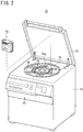
Fig. 2 is a perspective view of a centrifugation and separation apparatus. -
Fig. 3 is a schematic diagram illustrating a state of the blood bag system before a centrifugation step. -
Fig. 4 is a schematic diagram illustrating a state of the blood bag system after an air separation step and before a separation and separation step. -
Fig. 5 is a schematic diagram illustrating a hanging device and a blood bag system set on the hanging device, according a first embodiment of the present invention. -
Fig. 6 is a schematic diagram illustrating a hanging device and a blood bag system set on the hanging device, according a second embodiment of the present invention. -
Fig. 7 is a schematic diagram illustrating a hanging device and a blood bag system set on the hanging device, according a third embodiment of the present invention. -
Fig. 8 is a schematic diagram illustrating a hanging device according the third embodiment of the present invention, and illustrating a blood bag system set on the hanging device in a state different from the case inFig. 7 . - Hereinafter, a hanging device and a method for transferring an additive solution will now be described with preferred embodiments and attached drawings.
- Before describing configurations of hanging
devices 100A to 100C (refer toFigs. 5 to 8 ) according to embodiments of the present invention, ablood bag system 10 illustrated inFig. 1 will be described. Theblood bag system 10 is intended to centrifuge blood containing a plurality of components into a plurality of components having a different specific gravity (for example, two components including a relatively low specific gravity component and a relatively high specific gravity component) and to store and preserve the components separately in different bags. - The
blood bag system 10 according to the present embodiment is configured to centrifuge a residual blood component obtained by removing white blood cells and platelets from whole blood into two components, namely, plasma and concentrated red blood cells, and to store and preserve the plasma and the concentrated red blood cells separately in different bags. The hangingdevices 100A to 100C illustrated inFigs. 5 to 8 are used to hang a portion of the blood bag system 10 (separation processing unit 16 to be described below). - As illustrated in
Fig. 1 , theblood bag system 10 includes a blood collection unit 12, apreprocessing unit 14, and aseparation processing unit 16. The blood collection unit 12 collects blood (whole blood) from a donor. The preprocessingunit 14 removes a predetermined blood component from the whole blood. Theseparation processing unit 16 centrifuges the residual blood component obtained by removing the predetermined component into a plurality of blood components and stores (pools) the individual blood components in different bags. - The blood collection unit 12 will first be described. The blood collection unit 12 includes a
blood collection bag 18,blood collection tubes blood collection needle 24, a branchingconnector 26, and an initialflow blood bag 28. - The
blood collection bag 18 is a bag for storing (pooling) blood (whole blood) collected from a donor. Preferably, an anticoagulant is placed in theblood collection bag 18 in advance. The anticoagulant is typically a liquid and may include, for example, an ACD-A solution, a CPD solution, a CPDA-1 solution, a heparin sodium solution, or the like. The amount of the anticoagulant is appropriately determined depending on the amount of blood to be collected. - The
blood collection bag 18 is formed in a bag shape by overlapping flexible sheet materials formed of flexible resin such as polyvinyl chloride or polyolefin on each other and by fusion bonding (through thermal fusion bonding or high-frequency welding) or gluing on peripheral sealing portions of the sheet materials to each other. Similarly, the initialflow blood bag 28 is also formed in a bag shape. - One end of the proximal-side
blood collection tube 20 is connected to theblood collection bag 18. Aclamp 30 for closing or opening a flow path in theblood collection tube 20 is provided in the middle of theblood collection tube 20. One end of afrangible part 32 is connected to the other end of theblood collection tube 20. Thefrangible part 32 is configured such that the flow path is closed in an initial state and is then opened by performing breaking operation. - A
first port 26a of the branchingconnector 26 is connected to the other end of thefrangible part 32. One end of the distal-sideblood collection tube 22 is connected to asecond port 26b of the branchingconnector 26, and theblood collection needle 24 is connected to the other end of theblood collection tube 22. Acap 24a is attached to theblood collection needle 24 before use, and aneedle guard 24b is attached to theblood collection needle 24 after use. Theneedle guard 24b is movably arranged along the longitudinal direction of theblood collection tube 22. - One end of a branching
tube 34 is connected to athird port 26c of the branchingconnector 26. Aclamp 36 that closes or opens a flow path of the branchingtube 34 is provided in the middle of the branchingtube 34. The initialflow blood bag 28 is connected to the other end of the branchingtube 34. Asampling port 38 is connected to the initialflow blood bag 28. The direction and arrangement of the branchingconnector 26 are not limited to the configuration illustrated inFig. 1 but may be appropriately changed. - The preprocessing
unit 14 includes afilter 40, an inlet-side tube 42, and an outlet-side tube 44. Thefilter 40 removes predetermined cells. The inlet-side tube 42 is connected at its one end to theblood collection bag 18 and connected at its other end to an inlet of thefilter 40. The outlet-side tube 44 is connected at its one end to an outlet of thefilter 40 and connected at its other end to theseparation processing unit 16. - In the present embodiment, the
filter 40 is configured as a white blood cell removing filter. As the white blood cell removing filter, it is appropriate to use a filter having a structure that stores a liquid-passing porous body having numerous micropores communicating from one side surface to the other side surface thereof in a bag-shaped housing formed of a flexible resin sheet. In the present embodiment, thefilter 40 is configured to be able to supplement platelets, as well. - The inlet-
side tube 42 is a tube for transferreing the blood collected from a donor from theblood collection bag 18 to thefilter 40, and is connected to a top portion of theblood collection bag 18. In the present embodiment, afrangible part 46 is provided at a blood collection bag 18-side end of the inlet-side tube 42. Thefrangible part 46 has the same configuration and function as those of thefrangible part 32 described above. - The outlet-
side tube 44 is a tube for transferreing the residual blood components obtained by removing predetermined cells (in the present embodiment, white blood cells and platelets) using thefilter 40, to the separation processing unit 16 (specifically, aprimary bag 50 described below). Aclamp 48 that closes and opens a flow path of the outlet-side tube 44 is provided in the middle of the outlet-side tube 44. A clamp similar to theclamp 30 described above may be employed as theclamp 48. - Next, the
separation processing unit 16 will be described. Theseparation processing unit 16 includes a primary bag (first bag) 50, a subsidiary bag (third bag) 52, a medical fluid bag (second bag) 54, and atransfer line 55. The primary bag (first bag) 50 stores (pools) the residual blood component obtained by removing the predetermined cells using thefilter 40. The subsidiary bag (third bag) 52 stores and preserves a supernatant component obtained by centrifuging the blood component inside theprimary bag 50. The medical fluid bag (second bag) 54 stores a red blood cell preservation M (additive solution). Thetransfer line 55 is connected to theprimary bag 50, thesubsidiary bag 52, and themedical fluid bag 54. - Similarly to the
blood collection bag 18, theprimary bag 50, thesubsidiary bag 52 and themedical fluid bag 54 are each formed in a bag shape by overlapping flexible sheet materials formed of flexible resin such as polyvinyl chloride or polyolefin on each other and by fusion bonding (through thermal fusion bonding or high-frequency welding) or gluing on peripheral sealing portions of the sheet materials to each other.Slits 63 to 65 are provided on bottom portions of theprimary bag 50, thesubsidiary bag 52, and themedical fluid bag 54 so as to enable hanging each of the bags with their top portions facing downward. - The
primary bag 50 serves as both a bag for storing (pooling) the residual blood component obtained by removing the predetermined cells using thefilter 40 and a bag for preserving a sedimentary component (concentrated red blood cells) obtained by centrifuging the blood component. - The
transfer line 55 is a means to connect theprimary bag 50 with thesubsidiary bag 52 and to connect theprimary bag 50 with themedical fluid bag 54. In the exemplary illustration, thetransfer line 55 includes a first tube 56 (first bag-side tube) connected to theprimary bag 50, asecond tube 58 connected to thesubsidiary bag 52, a third tube 60 (second bag-side tube) connected to themedical fluid bag 54, and a branching connector 62 (branch section) connected to the first tothird tubes - A breakable
frangible part 66 is provided at one end (primary bag 50-side end) of thefirst tube 56 to prevent the blood component inside theprimary bag 50 from being transferred to other bags until the breaking operation is performed. Thefrangible part 66 has the same configuration and functionality as those of thefrangible part 32 described above. - The other end of the
first tube 56 is connected to thefirst port 62a of the branchingconnector 62. One end of thesecond tube 58 is connected to the secondport 62b of the branchingconnector 62. One end of thethird tube 60 is connected to thethird port 62c of the branchingconnector 62. The branchingconnector 62 is formed of a material harder than the material of the first tothird tubes - As the red blood cell preservation M contained in the
medical fluid bag 54, a MAP solution, an SAGM solution, OPTISOL, or the like, may be employed. A breakablefrangible part 68 is provided at the medical fluid bag 54-side end of thethird tube 60 to prevent the red blood cell preservation liquid M in themedical fluid bag 54 from being transferred to other bags. Thefrangible part 68 has the same configuration and functionality as those of thefrangible part 32 described above. - The tubes in the
blood bag system 10 are formed of transparent flexible resin. The clamps 30, 36 and 48 may be standard products that have been conventionally used. The clamps 30, 36, and 48 are preferably classified by different colors depending on a place or purpose of use. When theblood bag system 10 is sterilized or stored before use, theclamps - The
blood bag system 10 may be, for example, attached to a centrifugation andseparation apparatus 70 illustrated inFig. 2 in use. The centrifugation andseparation apparatus 70 is used to centrifuge the blood component stored inside theprimary bag 50 into two layers, namely, a plasma layer and a concentrated red blood cell layer, and deliver the plasma into thesubsidiary bag 52 while keeping the concentrated red blood cells to remain inside theprimary bag 50. - The centrifugation and
separation apparatus 70 has a box shape and includes amain body 71, alid 72, a centrifugal drum 74, six unit insertion holes 76, sixinsert units 78, and six pressers 80 (refer toFig. 3 , etc.). Thelid 72 is openable and closable on an upper surface. The centrifugal drum 74 is internally installed. The six unit insertion holes 76 are arranged inside the centrifugal drum 74 at a regular angular interval (60°). The sixinsert units 78 are insertable and removable respectively into/from the unit insertion holes 76. The sixpressers 80 provided at a center, and are capable of advancing and retreating in a rotational radial direction with respect to each of theinsert units 78. The centrifugation andseparation apparatus 70 is operated based on operation of anoperation unit 82 provided in front and is controlled by a microcomputer (not illustrated). - Typically six
insert units 78 are attached to the centrifugation andseparation apparatus 70. Alternatively, it is also allowable to attach five or less insert units (preferably, three or two insert units arranged at a regular angular interval) as long as the insert units are appropriately balanced. - Before the
blood bag system 10 is attached to the centrifugation andseparation apparatus 70 after the residual blood component obtained by filtering whole blood using thefilter 40 is transferred to theprimary bag 50 and stored therein, the outlet-side tube 44 is fusion-bonded to prevent leakage using a tube sealer, or the like, and is then cut. Accordingly, among theblood bag system 10, merely theseparation processing unit 16 and a portion of the outlet-side tube 44 are attached to theinsert unit 78. - Processing including collecting blood from a donor using the
blood bag system 10 illustrated inFig. 1 , removing white blood cells and platelets from collected blood, separating residual components into two layers of plasma and concentrated red blood cells, and then pooling the separated components in the separate bags can be performed by the following procedure, for example. - First, using the
blood collection needle 24, blood collection step is performed such that the skin of a donor is punctured and the blood is collected from the donor. In the blood collection step, a predetermined amount of initial flow of the blood (initial-flow-at-blood-collection) collected from a donor is stored in the initialflow blood bag 28 before the blood is collected into theblood collection bag 18. In this case, theclamp 36 is set to an open state while thefrangible part 32 is kept to a closed state (initial state). As a result, it is possible to block the entry of initial-flow-at-blood-collection into theblood collection tube 20 side, namely, theblood collection bag 18 side, and also possible to introduce the initial-flow-at-blood-collection into the initialflow blood bag 28 via theblood collection tube 22, the branchingconnector 26, and the branchingtube 34. - Next, by attaching a blood sampling tube (not illustrated) to the
sampling port 38, initial-flow-at-blood-collection is collected into the blood sampling tube. The initial-flow-at-blood-collection is used as blood sample for testing. Portions from the branchingconnector 26 to thesampling port 38 may be omitted depending on application. - After collection of the initial-flow-at-blood-collection is completed, the branching
tube 34 is closed by theclamp 36, and breaking operation is performed for thefrangible part 32 to open the flow path of theblood collection tube 20. At this time, when theclamp 30 is set to an open state, the blood from the donor flows sequentially through theblood collection tubes blood collection bag 18. - After a predetermined amount of blood is collected and pooled in the
blood collection bag 18, theblood collection tube 20 is closed by theclamp 30 so as not to let the blood in theblood collection bag 18 flow out. After theblood collection tube 20 is fusion-bonded and sealed by a tube sealer, or the like, theblood collection tube 20 is then cut at the sealed portion. - Then, with the
blood collection bag 18 being arranged in an upper position and theprimary bag 50 being arranged in a lower position, thefilter 40 is arranged in an intermediate position. Thereafter, breaking operation is performed on thefrangible part 46 provided at one end portion of the inlet-side tube 42 to open the flow path of the inlet-side tube 42. As a result, the whole blood in theblood collection bag 18 flows through the inlet-side tube 42 into thefilter 40, and with white blood cells and platelets removed in the course of passing through thefilter 40, flows through the outlet-side tube 44 into theprimary bag 50 to be collected therein. At this time, not only the blood from which white blood cells and platelets have been removed but also air existing in thefilter 40 flows into theprimary bag 50. - Then, the outlet-
side tube 44 is fusion-bonded and sealed at a position downstream of theclamp 48 using a tube sealer, or the like, and the outlet-side tube 44 is cut at the sealed portion. - Then, to separate the blood component collected in the
primary bag 50 into plasma and concentrated red blood cells and pool them in predetermined bags individually, theseparation processing unit 16 of theblood bag system 10 is attached to the centrifugation andseparation apparatus 70. At this time of attaching, the above-described breaking operation is performed on thefrangible part 66 so as to open the flow path of thefrangible part 66. The breaking operation of thefrangible part 66 may be performed before or after attaching theprimary bag 50 to the centrifugation andseparation apparatus 70. - Subsequently, the blood bag system 10 (specifically, separation processing unit 16) is attached to the
insert unit 78, and theinsert unit 78 is then inserted into theunit insertion hole 76 to achieve the state of the schematic diagram illustrated inFig. 3 . InFig. 3 , the directions A indicated by the double arrow represent radial directions of the centrifugal drum 74 of the centrifugation andseparation apparatus 70. More specifically, the direction A1 represents an inward radial direction and the direction A2 represents an outward radial direction. - The
primary bag 50, while being attached to theinsert unit 78, is held vertically (extending in an up-down direction), and stored in the centrifugation andseparation apparatus 70 such that the thickness direction of the bag main body is arranged in the directions A. With this arrangement, during rotation of the centrifugal drum 74 of the centrifugation andseparation apparatus 70, centrifugal force is applied to theprimary bag 50 in the A2 direction. - As illustrated in
Fig. 3 , the centrifugation andseparation apparatus 70 includes asensor 90 that detects the type of liquid passing through thefirst tube 56. Thesensor 90 includes, for example, a light-transmitting section and a light-receiving section and can determine the type of the liquid passing there between based on a light transmission level of the liquid. The centrifugation andseparation apparatus 70 further includes aclamp 92 and aclamp 94. Theclamp 92 is operable to open and close and switches open/close of the flow path of thesecond tube 58 by open/close operation. Theclamp 94 is operable to open and close and switches open/close of the flow path of thethird tube 60 by open/close operation. - Alternatively, it is also allowable to configure such that the
clamps second tube 58 and thethird tube 60 respectively beforehand and that an operation mechanism to open and close theclamps separation apparatus 70. - Next, the
lid 72 of the centrifugation andseparation apparatus 70 is closed, and thereafter, the centrifugation step and the separation-transfer step are automatically performed by operating theoperation unit 82. As illustrated inFig. 3 , theclamps third tubes primary bag 50. This air is the air that existed in thefilter 40 and flew into theprimary bag 50 when blood filtration is performed by thefilter 40. - First, in automatic operation of the centrifugation and
separation apparatus 70, the centrifugation step is performed by rotating the centrifugal drum 74, that is, the blood component pooled in theprimary bag 50 is separated into plasma and concentrated red blood cells. In the centrifugation step, the blood component pooled in theprimary bag 50 receives a centrifugal force. As a result, the concentrated red blood cells as a high specific gravity component are moved in the outward radial direction (direction A2), whereas the plasma as a low specific gravity component is moved in the inward radial direction (direction A1), and thus, the blood component is separated into two layers. - The centrifugation and
separation apparatus 70 performs an air separation step after the centrifugation step. In the air separation step, theclamp 94 is opened while the rotation of centrifugal drum 74 is maintained, thereby switching the flow path of thethird tube 60 to an open state. - Next, as illustrated in
Fig. 4 , theprimarybag 50 is pressed by displacing thepresser 80 in the outward radial direction (direction A2). Since the volume of theprimary bag 50 is reduced because it is clamped between thepresser 80 and the wall, air is discharged from inside theprimary bag 50. Accordingly, the air is flown into themedical fluid bag 54 via thefirst tube 56, the branchingconnector 62, and thethird tube 60. - The centrifugation and
separation apparatus 70 performs plasma separation and separation step after the air separation step. Specifically, after the air has flown out of theprimary bag 50, since thefirst tube 56 is directed toward the inner diameter side, the plasma located in the innermost diameter side starts to flow out of theprimary bag 50. At this time, when the flow of the plasma into thefirst tube 56 is detected by thesensor 90, thethird tube 60 is switched to a closed state by closing theclamp 94 while maintaining the rotation of the centrifugal drum 74, and together with this, thesecond tube 58 is switched to an open state by opening theclamp 92. This allows the plasma that has flown out of theprimary bag 50 to flow into thesubsidiarybag 52 via thefirst tube 56, the branchingconnector 62, and thesecond tube 58. - After the plasma has completely flown out of the
primary bag 50, the concentrated red blood cells start to flow out of theprimary bag 50. At this time, when the flow of the red blood cells into thefirst tube 56 is detected by thesensor 90, thepresser 80 is stopped, and the flow path of thesecond tube 58 is closed by closing theclamp 92. Accordingly, it is possible to block the entry of flow of the red blood cells into thesubsidiary bag 52. - After completion of the above-described separation-transfer step, the
separation processing unit 16 is taken out of theinsert unit 78 and thesecond tube 58 is fusion-bonded and sealed by a tube sealer, or the like, and thereafter, is cut, thereby separating thesubsidiary bag 52. - Welding, sealing and cutting of the
second tube 58 using the tube sealer, or the like, may also be performed within the centrifugation andseparation apparatus 70 using mechanical operation, by adding a tube-sealing function, cutting function, or the like, to theclamp 92. - Next, the addition step is performed manually. In this step, the red blood cell preservation liquid M is added to the concentrated redblood cells. The addition step can be performed, for example, by using the
hanging device 100A according to the first embodiment, illustrated inFig. 5 . The hangingdevice 100A is used when the red blood cell preservation liquid M is transferred from themedical fluid bag 54 to theprimary bag 50 using the height difference between theprimary bag 50 and themedical fluid bag 54, in order to add the red blood cell preservation liquid M to the concentrated red blood cells inside theprimary bag 50. - The hanging
device 100A includes abase 102, asupport column 104, and two hangingsections 106 and 108 (second bag hanging section, support mechanism). Thebase 102 is placed on an installation surface S. Thesupport column 104 is supported by thebase 102 and extends in the up-down direction. The hangingsections support column 104 with an interval in the up-down direction. Thebase 102 has a plurality oflegs 103 in an exemplary illustration. The form, however, is not limited to this, but may have a plate shape expanding in the horizontal direction. - Among the two hanging
sections section 106 provided relatively at an upper side (hereinafter, referred to as an "upper hanging section 106") is configured to be able to hang themedical fluid bag 54 such that ainflux portion 54a of themedical fluid bag 54 faces downward (namely, upside down). Specifically, theupper hanging section 106 is formed into a stick-like shape protruding in a direction (horizontal direction in the exemplary illustration) crossing thesupport column 104. Acurved hook section 107 is provided at a free end-side of theupper hanging section 106. By inserting thehook section 107 into theslit 65 provided on a bottom portion of themedical fluid bag 54, it is possible to hang themedical fluid bag 54 upside down. - Among the two hanging
sections section 108 provided relatively at lower side (hereinafter, referred to as an "lower hanging section 108") is configured to be able to hang theprimary bag 50 such that ainflux portion 50a of theprimary bag 50 faces downward (namely, upside down) at a position lower than themedical fluid bag 54 hung by theupper hanging section 106. - Specifically, the
lower hanging section 108 is formed into a stick-like shape protruding in a direction (horizontal direction in the exemplary illustration) crossing thesupport column 104. Acurved hook section 109 is provided at a free end-side of thelower hanging section 108. By inserting thehook section 109 into theslit 63 provided on a bottom portion of theprimary bag 50, it is possible to hang theprimary bag 50 upside down. - The
lower hanging section 108 configured in this manner functions as a support mechanism to support theprimary bag 50 in a predetermined state such that, when the red blood cell preservation liquid M is transferred from themedical fluid bag 54 to theprimary bag 50 using the height difference between theprimary bag 50 and themedical fluid bag 54, air from themedical fluid bag 54 stops in the middle of thetransfer line 55. - As an alternative means of hanging the
medical fluid bag 54 or theprimary bag 50 upside down besides thehook sections medical fluid bag 54 or theprimary bag 50, it is possible to hang themedical fluid bag 54 or theprimary bag 50 upside down. - In
Fig. 5 , theupper hanging section 106 and thelower hanging section 108 have difference lengths. The lengths, however, may be the same. - As illustrated in
Fig. 5 , the hangingdevice 100A may further include aheight adjustment mechanism 110 for adjusting the hanging height when hung by thelower hanging section 108. In an exemplary illustration, theheight adjustment mechanism 110 is slidable in the up-down direction with respect to thesupport column 104 and can hold an adjusted height position. As modification of theheight adjustment mechanism 110, it is allowable to employ a configuration that can adjust the hanging height using thelower hanging section 108 that can change its angle with respect to thesupport column 104. - In a case where the addition step is performed using the above-configured
hanging device 100A, the blood bag system 10 (separation processing unit 16) is set on thehanging device 100A as illustrated inFig. 5 . Specifically, theprimary bag 50 is hung by hooking theprimary bag 50 at a position of theslit 63 onto ahook section 109 of thelower hanging section 108 such that theinflux portion 50a of theprimary bag 50 faces downward. Next, themedical fluid bag 54 is hung by hooking themedical fluid bag 54 at a position of theslit 65 onto thehook section 107 of theupper hanging section 106 such that theinflux portion 54a of themedical fluid bag 54 faces downward. - In this case, in order to facilitate squeezing operation to be described below, it is preferable to arrange a liquid level Lv1 inside the
primary bag 50 to be at a position lower than the branchingconnector 62, as illustrated inFig. 5 . In thehanging device 100A, the hanging height of theprimary bag 50 is adjustable with theheight adjustment mechanism 110, and thus, it is possible to easily set the liquid level Lv1 inside theprimary bag 50 to a position lower than the branchingconnector 62. - In a case where it is difficult to provide the
height adjustment mechanism 110 in thehanging device 100A, it would be preferable that the position of thelower hanging section 108 has been set beforehand such that the liquid level Lv1 inside theprimary bag 50 comes at a position lower than the branchingconnector 62 with themedical fluid bag 54 and theprimary bag 50 being respectively hung on theupper hanging section 106 and thelower hanging section 108. - In this manner, when the
medical fluid bag 54 containing the red blood cell preservation liquid M is arranged upside down at a relatively high position, and when theprimary bag 50 containing the concentrated red blood cells is arranged upside down at a relatively low position, the redblood cell preservation liquid M inside themedical fluid bag 54 starts to move downward by gravity due to the height difference between themedical fluid bag 54 and theprimary bag 50. In this case, air exists in a top portion inside themedical fluid bag 54, namely, in a portion above the red blood cell preservation liquid M. - As a result, after flowing of the red blood cell preservation liquidMout of the
medical fluid bag 54 is finished, air existing inside themedical fluidbag 54 starts to flow toward thethird tube 60. In this case, the air moving inside thetransfer line 55 from themedical fluid bag 54 stops at a level corresponding to a liquid level Lv1 (or around this level) inside theprimary bag 50. In other words, the liquid level Lv1 inside theprimary bag 50 hung upside down is at a height in the middle of thetransfer line 55. Accordingly, since the liquid level Lv1 (or around this level) can be balanced with the liquid level of the red blood cell preservation liquid M inside thetransfer line 55, movement of air stops when the movement of the red blood cell preservation liquid M stops. As a result, the air from themedical fluid bag 54 is least likely to flow into theprimary bag 50. - Meanwhile, at a stage before starting the addition step, the
third tube 60 includes air inside itself and this air flows into theprimary bag 50 at an initial stage of the addition step. Fortunately, however, the amount of air inside thethird tube 60 is significantly less than the amount of air inside themedical fluid bag 54, and thus, the amount of air flowing into theprimary bag 50 at the addition step would be small. Accordingly, after completion of the addition step, the amount of air inside theprimary bag 50 is the amount that scarcely needs air bleeding operation. - When the movement of the redblood cell preservation liquid M and the movement of the air have stopped, operation to move the red blood cell preservation liquid M remaining in the flow path of the
transfer line 55 to the primary bag 50 (squeezing operation) is performed by squeezing thetransfer line 55 toward theprimary bag 50 side. In this exemplary case, however, unlike the state inFig. 5 , if the liquid level Lv1 inside theprimary bag 50 is at the height of the branchingconnector 62 or above, the air from themedical fluid bag 54 would stop at a position at the height of the branchingconnector 62 or above. This would make works complicated not only because the branchingconnector 62 hinders squeezing operation but also because thefirst tube 56 has to be sealed and cut after thethird tube 60 has been sealed and cut. - In contrast, in a case where the liquid level Lv1 inside the
primary bag 50 is at a position lower than the branchingconnector 62 as inFig. 5 , it is sufficient to squeeze thefirst tube 56 alone, and since the branchingconnector 62 would not hinder operation, it is possible to smoothly perform squeezing operation. Furthermore, it is sufficient that thefirst tube 56 alone is sealed and cut, and thus, the work would be simple. - With the above-described processing, it is possible to remove white blood cells and platelets from whole blood, separate residual blood components into two components, namely, plasma and concentrated red blood cells, and to store and preserve the plasma and the concentrated red blood cells separately in different bags (
primary bag 50 and the subsidiary bag 52). - As described above, with the hanging
device 100A according to the present embodiment, the air from themedical fluid bag 54 stops in the middle of thetransfer line 55 when the red blood cell preservation liquid M is transferred from themedical fluid bag 54 to theprimary bag 50 using the height difference between theprimary bag 50 and themedical fluid bag 54 in order to add the red blood cell preservation liquid M to the concentrated red blood cells inside theprimary bag 50. This can prevent the air from themedical fluid bag 54 from mixing into theprimary bag 50. Accordingly, after the red blood cell preservation liquid M has been added to the concentrated red blood cells, the amount of air inside theprimary bag 50 is the amount that scarcely needs air bleeding operation. As a result, it is possible to eliminate air bleeding operation after addition of the red blood cell preservation liquid M. - According to the present embodiment, by hanging the
primary bag 50 upside down, the liquid level Lv1 inside theprimary bag 50 comes at a position higher than theinflux portion 50a of theprimary bag 50 when the additive solution is transferred from the medical fluidbag54 to theprimary bag 50. Accordingly, the air moving inside thetransfer line 55 from themedical fluid bag 54 stops at a position of the liquid level Lv1 inside theprimary bag 50. As a result, it is possible, with a simple configuration, to appropriately prevent the air from themedical fluid bag 54 from mixing into theprimary bag 50. - The above-described
hanging device 100A is configured to arrange both theupper hanging section 106 and thelower hanging section 108 to be on the same stand (base 102 and support column 104). Alternatively, theupper hanging section 106 and thelower hanging section 108 may be provided on separate stands or constructions. - In the above-described addition step, the
primary bag 50 may be hung upside down by hanging theprimary bag 50 at theslit 63 on asecond port 62b of the branchingconnector 62 instead of hanging theprimary bag 50 upside down on thelower hanging section 108. Even with this method, the air moving inside thetransfer line 55 from themedical fluid bag 54 stops at a level corresponding to a liquid level Lv1 inside theprimary bag 50. Accordingly, similarly to the addition step inFig. 5 , it is possible to appropriately prevent the air from themedical fluid bag 54 from mixing into theprimary bag 50. Furthermore, it is also possible to configure to provide a protruding portion (e.g., another port) capable of hanging theprimary bag 50 at the position of theslit 63, on the branchingconnector 62, and hang theprimary bag 50 upside down on the protruding portion. In a case where theprimary bag 50 is hung on the branchingconnector 62, thelower hanging section 108 can be omitted. - The above-described addition step can be performed by using a
hanging device 100B according to a second embodiment illustrated inFig. 6 . On the hangingdevice 100B, constituent elements shared with the hangingdevice 100A have the same reference signs. The hangingdevice 100B includes abag mounting section 112 for mounting theprimary bag 50, instead of thelower hanging section 108 on thehanging device 100A described above. - The
bag mounting section 112 is provided below theupper hanging section 106 and capable of supporting theprimary bag 50 diagonally with respect to the horizontal direction to arrange theprimary bag 50 to be gradually lowered toward theinflux portion 50a side of theprimary bag 50, at a position lower than themedical fluid bag 54 hung by theupper hanging section 106. - As illustrated in
Fig. 6 , thebag mounting section 112 includes, for example, aplatform 114 and an inclined table 116. Theplatform 114 is supported by thesupport column 104 and extends in the horizontal direction. The inclined table 116 is provided on theplatform 114. By mounting theprimary bag 50 on adiagonal mounting surface 116a forming an upper surface of the inclined table 116 with theinflux portion 50a coming on a lower side, it is possible to support theprimary bag 50 diagonally while keeping the state where theinflux portion 50a of theprimary bag 50 is at a relatively lower position and a bottom portion of theprimary bag 50 is at a relatively higher position. - It is preferable to set the relative positional relationship between the
bag mounting section 112 and theupper hanging section 106 such that the liquid level Lv1 inside theprimary bag 50 comes at a position lower than the branchingconnector 62 in a state where themedical fluid bag 54 is hung by theupper hanging section 106 and theprimary bag 50 is mounted on thebag mounting section 112. Thebag mounting section 112 may be configured to be height-adjustable with respect to thesupport column 104. - The
bag mounting section 112 configured in this manner functions as a support mechanism to support theprimary bag 50 in a predetermined state such that air from themedical fluid bag 54 stops in the middle of thetransfer line 55 when the red blood cell preservation liquid M is transferred from themedical fluid bag 54 to theprimary bag 50 using the height difference between theprimary bag 50 and themedical fluid bag 54. - In a case where the addition step is performed using the above-configured
hanging device 100B, the blood bag system 10 (separation processing unit 16) is mounted on thehanging device 100B as illustrated inFig. 6 . Specifically, theprimary bag 50 is supported diagonally while keeping the state where theinflux portion 50a of theprimary bag 50 is at a relatively lower position and the liquid level Lv1 inside theprimary bag 50 is at a relatively higher position by mounting theprimary bag 50 on the inclined table 116 of thebag mounting section 112 with theinflux portion 50a coming on a lower side. Next, themedical fluid bag 54 is hung by hooking themedical fluid bag 54 at a position of theslit 65 onto thehook section 107 of theupper hanging section 106 such that theinflux portion 54a of themedical fluid bag 54 faces downward. As a result, the liquid level Lv1 inside theprimary bag 50 comes at a position lower than the branchingconnector 62. - In this manner, when the
medical fluid bag 54 containing the red blood cell preservation liquid M is arranged upside down at a relatively high position, and when theprimary bag 50 containing the concentrated red blood cells is arranged at a relatively low position, the red blood cell preservation liquid M in themedical fluid bag 54 starts to move downward by gravity due to the height difference between themedical fluid bag 54 and theprimary bag 50. In this case, air exists in a top portion inside themedical fluid bag 54, namely, in a portion above the red blood cell preservation liquid M. - As a result, after flowing of the red blood cell preservation liquid M out of the
medical fluid bag 54 is finished, air existing inside themedical fluidbag 54 starts to flow toward thethird tube 60. In this case, the air moving inside thetransfer line 55 from themedical fluid bag 54 stops at a level corresponding to a liquid level Lv1 (or around this level) inside theprimary bag 50. As a result, the air from themedical fluid bag 54 is least likely to flow into theprimary bag 50. - When the movement of the redblood cell preservation liquid M and movement of the air stop, squeezing operation is performed similarly to the case of the hanging
device 100A. On the hangingdevice 100B, the red blood cell preservation liquid M remaining inside thetransfer line 55 is at a position lower than the branchingconnector 62. Accordingly, it is sufficient to squeeze thefirst tube 56 alone. Accordingly, since the branchingconnector 62 does not hinder operation, it is possible to smoothly perform squeezing operation. - As described above, even with the hanging
device 100B, it is possible to prevent the air from themedical fluid bag 54 from mixing into theprimary bag 50. Accordingly, it is possible to eliminate air bleeding operation after addition of the red blood cell preservation liquid M. - On the hanging
device 100B, by disposing theprimary bag 50 diagonally with itsinflux portion 50a coming on the lower side, the liquid level inside theprimarybag 50 comes at a position higher than theinflux portion 50a of theprimary bag 50 when the red blood cell preservation liquid M is transferred from themedical fluid bag 54 to theprimary bag 50. Accordingly, the air moving inside thetransfer line 55 from themedical fluid bag 54 stops at a position of the liquid level Lv1 inside theprimary bag 50. As a result, it is possible, with a simple configuration, to appropriately prevent the air from themedical fluid bag 54 from mixing into theprimary bag 50. - The above-described
hanging device 100B is configured to arrange both theupper hanging section 106 and thebag mounting section 112 to be on the same stand (base 102 and support column 104). Alternatively, theupper hanging section 106 and thebag mounting section 112 may be provided on separate stands or constructions. - The above-described addition step can be performed by using a hanging device 100C according to a third embodiment illustrated in
Fig. 7 . On the hanging device 100C, constituent elements shared with the hangingdevice 100A have the same reference signs. The hanging device 100C includes abag mounting section 118 for mounting theprimary bag 50, and atube supporting section 120 that supports a portion of thetransfer line 55, instead of the above-describedlower hanging section 108 in thehanging device 100A. - The
bag mounting section 118 is provided below theupper hanging section 106 and capable of supporting theprimary bag 50 horizontally at a position lower than themedical fluid bag 54 hung by theupper hanging section 106. - The
tube supporting section 120 is supported by thesupport column 104 at a height between theupper hanging section 106 and thebag mounting section 118. Thetube supporting section 120 supports thetransfer line 55 so as to form a high-level site P1, and low-level sites P2, and P3 in thetransfer line 55. The high-level site P1 is located at a position higher than the liquid level Lv1 inside theprimary bag 50. The low-level sites P2 and P3 are located at positions lower than the high-level site P1 on both sides on the flow path of the high-level site P1. InFig. 7 , aloop 57 is formed on thefirst tube 56. Thetube supporting section 120 supports thefirst tube 56 by allowing thetube supporting section 120 passing inside theloop 57. - In
Fig. 7 , thetube supporting section 120 is supported by thesupport column 104 via theheight adjustment mechanism 110 similar to theheight adjustment mechanism 110 illustrated inFig. 5 . The height of thetube supporting section 120 can be adjusted by theheight adjustment mechanism 110. - It is preferable to set the relative positional relationship between the
upper hanging section 106, thebag mounting section 118, and thetube supporting section 120 such that the high-level site P1 comes at a position lower than the branchingconnector 62 in a state where themedical fluid bag 54 is hung by theupper hanging section 106 and theprimary bag 50 is mounted on thebag mounting section 118, and a portion of thetransfer line 55 is supported by thetube supporting section 120. - Each of the
bag mounting section 118 and thetube supporting section 120 configured as above functions as a support mechanism to support theprimary bag 50 in a predetermined state such that air from themedical fluid bag 54 stops in the middle of thetransfer line 55 when the red blood cell preservation liquid M is transferred from themedical fluid bag 54 to theprimary bag 50 using the height difference between theprimary bag 50 and themedical fluid bag 54. - In a case where the addition step is performed using the above-configured hanging device 100C, the blood bag system 10 (separation processing unit 16) is set on the hanging device 100C as illustrated in
Fig. 7 . Specifically, theprimary bag 50 is mounted on its side on thebag mounting section 118. Next, theloop 57 is formed in the middle of the transfer line 55 (in an exemplary illustration, the first tube 56). Then, by hanging theloop 57 on thetube supporting section 120, thetube supporting section 120 supports thetransfer line 55. - Next, the
medical fluid bag 54 is hung by hooking themedical fluid bag 54 at a position of theslit 65 onto thehook section 107 of theupper hanging section 106 such that theinflux portion 54a of themedical fluid bag 54 faces downward. As a result, the high-level site P1 is formed in thetransfer line 55, at a position higher than the liquid level Lv1 inside the primary bag50, and together with this, a liquid level Lv2 of the high-level site P1 comes at a position lower than the branchingconnector 62. - In this manner, when the
medical fluid bag 54 containing the red blood cell preservation liquid M is arranged upside down at a relatively high position, and when theprimary bag 50 containing the concentrated red blood cells is arranged at a relatively low position, the red blood cell preservation liquid M in themedical fluid bag 54 starts to move downward by gravity due to the height difference between themedical fluid bag 54 and theprimary bag 50. In this case, air exists in a top portion inside themedical fluid bag 54, namely, in a portion above the red blood cell preservation liquid M. - As a result, after flowing of the red blood cell preservation liquidMout of the
medical fluid bag 54 is finished, air existing inside themedical fluidbag 54 starts to flow toward thethird tube 60. In this case, the air moving inside thetransfer line 55 from themedical fluid bag 54 stops at a level corresponding to the liquid level Lv2 (or around this level) of the high-level site P1. As a result, the air from themedical fluid bag 54 is least likely to flow into theprimary bag 50. - When the movement of the redblood cell preservation liquid M and movement of the air stop, squeezing operation is performed similarly to the case of the hanging
device 100A. On the hanging device 100C, the red blood cell preservation liquid M remaining in thetransfer line 55 is at a position lower than the branchingconnector 62. Accordingly, it is sufficient to squeeze thefirst tube 56 alone. Accordingly, since the branchingconnector 62 does not hinder operation, it is possible to smoothly perform squeezing operation. - As described above, even with the hanging device 100C, it is possible to prevent the air coming from the
medical fluid bag 54 from mixing into theprimary bag 50. Accordingly, it is possible to eliminate air bleeding operation after addition of the red blood cell preservation liquid M. - In addition, in the case where the hanging device 100C is applied, when the red blood cell preservation liquid M is transferred from the
medical fluid bag 54 to theprimary bag 50, the air moving inside thetransfer line 55 from themedical fluid bag 54 stops at a position of the liquid level Lv2 (or around this level) of the high-level site P1. As a result, it is possible, with a simple configuration, to appropriately prevent the air from themedical fluid bag 54 from mixing into theprimary bag 50. - In a case where the addition step is performed using the hanging device 100C, the blood bag system 10 (separation processing unit 16) may be set as illustrated in
Fig. 8 . In this case,transfer line 55 is supported by thetube supporting section 120 with a portion in the middle of the transfer line 55 (in an exemplary illustration, the first tube 56) winding vertically. With this configuration, the high-level site P1, and the low-level sites P2, and P3 are formed in thetransfer line 55. The high-level site P1 is located at a position higher than the liquid level Lv1 inside theprimary bag 50. The low-level sites P2 and P3 are located at positions lower than the high-level site P1 on both sides on the flow path of the high-level site P1. - Even in a case of
Fig. 8 , that is, in a case where the addition step is performed while the blood bag system 10 (separation processing unit 16) is set on the hanging device 100C, the air moving inside thetransfer line 55 from themedical fluid bag 54 stops at a position of the liquid level Lv2 (or around this level) of the high-level site P1. Accordingly, it is possible to prevent the air from themedical fluid bag 54 from mixing into theprimary bag 50. - The above-described hanging device 100C is configured to arrange the
upper hanging section 106, thebag mounting section 118, and thetube supporting section 120 to be on the same stand (base 102 and support column 104). Alternatively, theupper hanging section 106, thebag mounting section 118, and thetube supporting section 120 may be provided on separate stands or constructions. - In the addition step using the hanging device 100C, the portion in the middle of the transfer line 55 (first tube 56) may be hung on the
second port 62b on the branchingconnector 62 instead of hanging the portion in the middle of the transfer line 55 (first tube 56) on thetube supporting section 120. With this configuration, the high-level site P1, and the low-level sites P2, and P3 are formed in thetransfer line 55. The high-level site P1 is located at a position higher than the liquid level Lv1 inside theprimary bag 50. The low-level sites P2 and P3 are located at positions lower than the high-level site P1 on both sides on the flow path of the high-level site P1. As a result, it is possible, similarly to the addition steps inFigs. 6 and 7 , to appropriately prevent the air from themedical fluid bag 54 from mixing into theprimary bag 50. Furthermore, it is also allowable to provide a protruding portion (e.g., another port) capable of hanging the portion in the middle of thetransfer line 55 on the branchingconnector 62, and hang the portion in the middle of thetransfer line 55 on the protruding portion. Note that in a case the portion in the middle of thetransfer line 55 is hung on the branchingconnector 62, thetube supporting section 120 can be omitted. - In the above, preferred embodiments regarding the present invention have been described. It should be readily apparent however, that the present invention is not intended to be limited to the above embodiments but various modifications are possible without departing from the scope of the present invention.
Claims (13)
- Hanging devices (100A to 100C) configured to hang a blood bag system (10) comprising:a first bag (50) containing a blood component;a second bag (54) containing additive solution (M); anda transfer line (55) that forms a flow path between the first bag (50) and the second bag (54),the hanging devices (100A to 100C) comprising:a second bag hanging section (106) configured to hang the second bag (54) such that a influx portion (54a) of the second bag (54) faces downward; andsupport mechanisms (108, 112, 118, and 120) configured to support the first bag (50) or the transfer line (55) in a predetermined state such that, when the additive solution (M) is transferred from the second bag (54) to the first bag (50) using a height difference between the first bag (50) and the second bag (54), air from the second bag (54) stops in the middle of the flow path.
- The hanging device (100A) according to claim 1,
wherein the support mechanism (108) hangs the first bag (50) such that a influx portion (50a) of the first bag (50) faces downward at a position lower than the second bag (54) hung by the second bag hanging section (106). - The hanging device (100B) according to claim 1,
wherein the support mechanism (112) supports the first bag (50) diagonally with respect to a horizontal direction to arrange the first bag (50) to be gradually lowered toward the influx portion (50a) of the first bag (50) at a position lower than the second bag (54) hung by the second bag hanging section (106). - The hanging devices (100A and 100B) according to claim 2 or 3,
wherein the transfer line (55) includes a first bag-side tube (56) formed of a flexible material connected to the first bag (50), asecondbag-sidetube (60) formedofaflexiblematerial connected to the second bag (54), and a branch section (62) formed to be harder than the first bag-side tube (56) and the second bag-side tube (60) and provided between the first bag-side tube (56) and the second bag-side tube (60), and
the support mechanisms (108 and 112) arrange a liquid level (Lv1) inside the first bag (50) to be at a position lower than the branch section (62). - The hanging device (100C) according to claim 1,
wherein the support mechanisms (118 and 120) support the first bag (50) and the transfer line (55) so as to form, in the transfer line (55), a high-level site (P1) existing at a position higher than the liquid level (Lv1) inside the first bag (50), and low-level sites (P2 and P3) existing at positions lower than the high-level site (P1) on both sides of the flow path of the high-level site (P1). - The hanging devices (100C) according to claim 5,
wherein the transfer line (55) includes a first bag-side tube (56) formed of a flexible material connected to the first bag (50), asecondbag-sidetube (60) formedofaflexiblematerial connected to the second bag (54), and a branch section (62) formed to be harder than the first bag-side tube (56) and the second bag-side tube (60) and provided between the first bag-side tube (56) and the second bag-side tube (60), and
the support mechanisms (118 and 120) arrange the high-level site (P1) to be at a position lower than the branch section (62) . - The method for transferring an additive solution targeted at a blood bag system (10) including a first bag (50) containing abloodcomponent, asecondbag (54) containing additive solution (M), and a transfer line (55) that forms a flow path between the first bag (50) and the second bag (54), the method being configured to transfer the additive solution (M) from the second bag (54) to the first bag (50),
The method for transferring the additive solution comprising:a support step of supporting the first bag (50) or the transfer line (55) in a predetermined state such that, when the additive solution (M) is transferred from the second bag (54) to the first bag (50) using a height difference between the first bag (50) and the second bag (54), air from the second bag (54) stops in the middle of the flow path; anda hanging step of hanging the second bag (54) such that a influx portion (54a) of the second bag (54) faces downward. - The method for transferring the additive solution according to claim 7,
wherein the support step hangs the first bag (50) such that a influx portion (50a) of the first bag (50) faces downward at a position lower than the second bag (54) hung in the hanging step. - The method for transferring the additive solution according to claim 7,
wherein the support step supports the first bag (50) diagonally with respect to a horizontal direction to arrange the first bag (50) to be gradually lowered toward the influx portion (50a) of the first bag (50) at a position lower than second bag (54) to be hung. - The method for transferring the additive solution according to claim 8 or 9,
wherein the transfer line (55) includes a first bag-side tube (56) formed of a flexible material connected to the first bag (50), asecondbag-sidetube (60) formedofaflexiblematerial connected to the second bag (54), and a branch section (62) formed to be harder than the first bag-side tube (56) and the second bag-side tube (60) and provided between the first bag-side tube (56) and the second bag-side tube (60), and
the support step arranges a liquid level (Lv1) inside the first bag (50) to be at a position lower than the branch section (62). - The method for transferring the additive solution according to claim 7,
wherein the support step supports the first bag (50) and the transfer line (55) so as to form, in the transfer line (55), a high-level site (P1) existing at a position higher than the liquid level (Lv1) inside the first bag (50), and low-level sites (P2 and P3) existing at positions lower than the high-level site (P1), on both sides of the flow path of the high-level site (P1). - The method for transferring the additive solution according to claim 11,
wherein the transfer line (55) includes a first bag-side tube (56) formed of a flexible material connected to the first bag (50), asecondbag-sidetube (60) formedofaflexiblematerial connected to the second bag (54), and a branch section (62) formed to be harder than the first bag-side tube (56) and the second bag-side tube (60) and provided between the first bag-side tube (56) and the second bag-side tube (60), and
the support step arranges the high-level site (P1) to be at a position lower than the branch section (62). - The method for transferring the additive solution according to any one of claims 7 to 12,
wherein the blood component is a concentrated red blood cell and the additive solution (M) is a red blood cell preservation.
Applications Claiming Priority (2)
| Application Number | Priority Date | Filing Date | Title |
|---|---|---|---|
| JP2014035141 | 2014-02-26 | ||
| PCT/JP2015/054418 WO2015129520A1 (en) | 2014-02-26 | 2015-02-18 | Suspension jig and method for transporting additive solution |
Publications (3)
| Publication Number | Publication Date |
|---|---|
| EP3111971A1 true EP3111971A1 (en) | 2017-01-04 |
| EP3111971A4 EP3111971A4 (en) | 2017-12-20 |
| EP3111971B1 EP3111971B1 (en) | 2020-12-09 |
Family
ID=54008841
Family Applications (1)
| Application Number | Title | Priority Date | Filing Date |
|---|---|---|---|
| EP15754993.2A Active EP3111971B1 (en) | 2014-02-26 | 2015-02-18 | Suspension jig and method for transporting additive solution |
Country Status (4)
| Country | Link |
|---|---|
| US (1) | US20170043071A1 (en) |
| EP (1) | EP3111971B1 (en) |
| JP (1) | JP6574411B2 (en) |
| WO (1) | WO2015129520A1 (en) |
Families Citing this family (7)
| Publication number | Priority date | Publication date | Assignee | Title |
|---|---|---|---|---|
| WO2016134317A1 (en) | 2015-02-20 | 2016-08-25 | Terumo Bct, Inc. | Composite liquid bag system holder |
| US20200289987A1 (en) | 2016-03-14 | 2020-09-17 | Pendotech | Processing System for Multiple Tangential Flow Filtration Stations in Bioprocessing Applications |
| JP6779676B2 (en) * | 2016-06-27 | 2020-11-04 | テルモ株式会社 | Blood bag system processing method and workstation |
| JP6719350B2 (en) * | 2016-09-20 | 2020-07-08 | テルモ株式会社 | Medical preparation division unit and medical preparation division method |
| EP3548108B1 (en) | 2016-12-02 | 2024-01-31 | Terumo BCT, Inc. | Composite fluid separation |
| JP6865327B2 (en) * | 2019-02-20 | 2021-04-28 | テルモ株式会社 | Blood bag system |
| US20220143383A1 (en) * | 2019-03-27 | 2022-05-12 | Terumo Kabushiki Kaisha | Blood bag system with multiple locking clamp |
Family Cites Families (11)
| Publication number | Priority date | Publication date | Assignee | Title |
|---|---|---|---|---|
| US3177870A (en) * | 1960-11-10 | 1965-04-13 | Abbott Lab | Secondary administration system |
| JPS4923711B1 (en) * | 1969-07-08 | 1974-06-18 | ||
| US4258723A (en) * | 1978-08-01 | 1981-03-31 | Sbr Lab, Inc. | Biological/pharmaceutical fluid collection and mixing system and method |
| US4267837A (en) * | 1979-09-27 | 1981-05-19 | Sbr Lab Inc. | Blood collection monitoring device and method |
| US5098371A (en) * | 1987-10-24 | 1992-03-24 | Kawasumi Laboratories, Inc. | Switch bag type blood gathering set |
| US4977850A (en) * | 1989-12-04 | 1990-12-18 | King Morris T | Signal apparatus |
| WO2000062840A1 (en) * | 1999-04-20 | 2000-10-26 | Heim Medizintechnik Gmbh | Device for separating blood into individual components and/or groups of said components |
| US6428712B1 (en) * | 2000-04-06 | 2002-08-06 | Hemasure, Inc. | Gravity driven liquid filtration system and method for filtering biological liquid |
| WO2004101034A1 (en) * | 2003-05-13 | 2004-11-25 | Keuning Shun Dirk | Mobile drip stand |
| US7854845B2 (en) * | 2003-09-05 | 2010-12-21 | Hemerus Medical Llc | Biological fluid filtration apparatus |
| JP4430373B2 (en) * | 2003-10-23 | 2010-03-10 | テルモ株式会社 | Blood separation device |
-
2015
- 2015-02-18 JP JP2016505156A patent/JP6574411B2/en active Active
- 2015-02-18 WO PCT/JP2015/054418 patent/WO2015129520A1/en not_active Ceased
- 2015-02-18 EP EP15754993.2A patent/EP3111971B1/en active Active
- 2015-02-18 US US15/120,791 patent/US20170043071A1/en not_active Abandoned
Also Published As
| Publication number | Publication date |
|---|---|
| JP6574411B2 (en) | 2019-09-11 |
| WO2015129520A1 (en) | 2015-09-03 |
| EP3111971B1 (en) | 2020-12-09 |
| JPWO2015129520A1 (en) | 2017-03-30 |
| EP3111971A4 (en) | 2017-12-20 |
| US20170043071A1 (en) | 2017-02-16 |
Similar Documents
| Publication | Publication Date | Title |
|---|---|---|
| EP3111971B1 (en) | Suspension jig and method for transporting additive solution | |
| US7648452B2 (en) | Apparatus for blood component separation | |
| EP1627651B1 (en) | Method and apparatus for blood component separation | |
| JP5555356B2 (en) | Blood bag system | |
| DK2869864T3 (en) | Apparatus for the extraction of a blood component contained in a bag system | |
| JP5977444B2 (en) | Blood bag system | |
| JP2015104449A (en) | Blood bag system and tube holder | |
| JP2019532692A (en) | Blood bag system and blood processing method | |
| JP6672262B2 (en) | Centrifuge and segment holder | |
| JP2015159856A (en) | blood bag system | |
| JP2015159855A (en) | Blood bag system | |
| JP6779676B2 (en) | Blood bag system processing method and workstation | |
| JP6456734B2 (en) | Hanging jig and additive liquid transfer method | |
| JP6267992B2 (en) | Blood bag system | |
| JP6297357B2 (en) | Blood bag system |
Legal Events
| Date | Code | Title | Description |
|---|---|---|---|
| PUAI | Public reference made under article 153(3) epc to a published international application that has entered the european phase |
Free format text: ORIGINAL CODE: 0009012 |
|
| STAA | Information on the status of an ep patent application or granted ep patent |
Free format text: STATUS: REQUEST FOR EXAMINATION WAS MADE |
|
| 17P | Request for examination filed |
Effective date: 20160823 |
|
| AK | Designated contracting states |
Kind code of ref document: A1 Designated state(s): AL AT BE BG CH CY CZ DE DK EE ES FI FR GB GR HR HU IE IS IT LI LT LU LV MC MK MT NL NO PL PT RO RS SE SI SK SM TR |
|
| AX | Request for extension of the european patent |
Extension state: BA ME |
|
| DAX | Request for extension of the european patent (deleted) | ||
| A4 | Supplementary search report drawn up and despatched |
Effective date: 20171117 |
|
| RIC1 | Information provided on ipc code assigned before grant |
Ipc: A61M 1/02 20060101AFI20171113BHEP |
|
| STAA | Information on the status of an ep patent application or granted ep patent |
Free format text: STATUS: EXAMINATION IS IN PROGRESS |
|
| 17Q | First examination report despatched |
Effective date: 20190621 |
|
| GRAP | Despatch of communication of intention to grant a patent |
Free format text: ORIGINAL CODE: EPIDOSNIGR1 |
|
| STAA | Information on the status of an ep patent application or granted ep patent |
Free format text: STATUS: GRANT OF PATENT IS INTENDED |
|
| INTG | Intention to grant announced |
Effective date: 20200708 |
|
| GRAS | Grant fee paid |
Free format text: ORIGINAL CODE: EPIDOSNIGR3 |
|
| GRAA | (expected) grant |
Free format text: ORIGINAL CODE: 0009210 |
|
| STAA | Information on the status of an ep patent application or granted ep patent |
Free format text: STATUS: THE PATENT HAS BEEN GRANTED |
|
| AK | Designated contracting states |
Kind code of ref document: B1 Designated state(s): AL AT BE BG CH CY CZ DE DK EE ES FI FR GB GR HR HU IE IS IT LI LT LU LV MC MK MT NL NO PL PT RO RS SE SI SK SM TR |
|
| REG | Reference to a national code |
Ref country code: GB Ref legal event code: FG4D |
|
| REG | Reference to a national code |
Ref country code: AT Ref legal event code: REF Ref document number: 1342726 Country of ref document: AT Kind code of ref document: T Effective date: 20201215 Ref country code: CH Ref legal event code: EP |
|
| REG | Reference to a national code |
Ref country code: DE Ref legal event code: R096 Ref document number: 602015063233 Country of ref document: DE |
|
| REG | Reference to a national code |
Ref country code: IE Ref legal event code: FG4D |
|
| PG25 | Lapsed in a contracting state [announced via postgrant information from national office to epo] |
Ref country code: NO Free format text: LAPSE BECAUSE OF FAILURE TO SUBMIT A TRANSLATION OF THE DESCRIPTION OR TO PAY THE FEE WITHIN THE PRESCRIBED TIME-LIMIT Effective date: 20210309 Ref country code: FI Free format text: LAPSE BECAUSE OF FAILURE TO SUBMIT A TRANSLATION OF THE DESCRIPTION OR TO PAY THE FEE WITHIN THE PRESCRIBED TIME-LIMIT Effective date: 20201209 Ref country code: RS Free format text: LAPSE BECAUSE OF FAILURE TO SUBMIT A TRANSLATION OF THE DESCRIPTION OR TO PAY THE FEE WITHIN THE PRESCRIBED TIME-LIMIT Effective date: 20201209 Ref country code: GR Free format text: LAPSE BECAUSE OF FAILURE TO SUBMIT A TRANSLATION OF THE DESCRIPTION OR TO PAY THE FEE WITHIN THE PRESCRIBED TIME-LIMIT Effective date: 20210310 |
|
| REG | Reference to a national code |
Ref country code: AT Ref legal event code: MK05 Ref document number: 1342726 Country of ref document: AT Kind code of ref document: T Effective date: 20201209 |
|
| PG25 | Lapsed in a contracting state [announced via postgrant information from national office to epo] |
Ref country code: BG Free format text: LAPSE BECAUSE OF FAILURE TO SUBMIT A TRANSLATION OF THE DESCRIPTION OR TO PAY THE FEE WITHIN THE PRESCRIBED TIME-LIMIT Effective date: 20210309 Ref country code: SE Free format text: LAPSE BECAUSE OF FAILURE TO SUBMIT A TRANSLATION OF THE DESCRIPTION OR TO PAY THE FEE WITHIN THE PRESCRIBED TIME-LIMIT Effective date: 20201209 Ref country code: LV Free format text: LAPSE BECAUSE OF FAILURE TO SUBMIT A TRANSLATION OF THE DESCRIPTION OR TO PAY THE FEE WITHIN THE PRESCRIBED TIME-LIMIT Effective date: 20201209 |
|
| REG | Reference to a national code |
Ref country code: NL Ref legal event code: MP Effective date: 20201209 |
|
| PG25 | Lapsed in a contracting state [announced via postgrant information from national office to epo] |
Ref country code: NL Free format text: LAPSE BECAUSE OF FAILURE TO SUBMIT A TRANSLATION OF THE DESCRIPTION OR TO PAY THE FEE WITHIN THE PRESCRIBED TIME-LIMIT Effective date: 20201209 Ref country code: HR Free format text: LAPSE BECAUSE OF FAILURE TO SUBMIT A TRANSLATION OF THE DESCRIPTION OR TO PAY THE FEE WITHIN THE PRESCRIBED TIME-LIMIT Effective date: 20201209 |
|
| REG | Reference to a national code |
Ref country code: LT Ref legal event code: MG9D |
|
| PG25 | Lapsed in a contracting state [announced via postgrant information from national office to epo] |
Ref country code: LT Free format text: LAPSE BECAUSE OF FAILURE TO SUBMIT A TRANSLATION OF THE DESCRIPTION OR TO PAY THE FEE WITHIN THE PRESCRIBED TIME-LIMIT Effective date: 20201209 Ref country code: SK Free format text: LAPSE BECAUSE OF FAILURE TO SUBMIT A TRANSLATION OF THE DESCRIPTION OR TO PAY THE FEE WITHIN THE PRESCRIBED TIME-LIMIT Effective date: 20201209 Ref country code: PT Free format text: LAPSE BECAUSE OF FAILURE TO SUBMIT A TRANSLATION OF THE DESCRIPTION OR TO PAY THE FEE WITHIN THE PRESCRIBED TIME-LIMIT Effective date: 20210409 Ref country code: RO Free format text: LAPSE BECAUSE OF FAILURE TO SUBMIT A TRANSLATION OF THE DESCRIPTION OR TO PAY THE FEE WITHIN THE PRESCRIBED TIME-LIMIT Effective date: 20201209 Ref country code: SM Free format text: LAPSE BECAUSE OF FAILURE TO SUBMIT A TRANSLATION OF THE DESCRIPTION OR TO PAY THE FEE WITHIN THE PRESCRIBED TIME-LIMIT Effective date: 20201209 Ref country code: EE Free format text: LAPSE BECAUSE OF FAILURE TO SUBMIT A TRANSLATION OF THE DESCRIPTION OR TO PAY THE FEE WITHIN THE PRESCRIBED TIME-LIMIT Effective date: 20201209 Ref country code: CZ Free format text: LAPSE BECAUSE OF FAILURE TO SUBMIT A TRANSLATION OF THE DESCRIPTION OR TO PAY THE FEE WITHIN THE PRESCRIBED TIME-LIMIT Effective date: 20201209 |
|
| PG25 | Lapsed in a contracting state [announced via postgrant information from national office to epo] |
Ref country code: PL Free format text: LAPSE BECAUSE OF FAILURE TO SUBMIT A TRANSLATION OF THE DESCRIPTION OR TO PAY THE FEE WITHIN THE PRESCRIBED TIME-LIMIT Effective date: 20201209 Ref country code: AT Free format text: LAPSE BECAUSE OF FAILURE TO SUBMIT A TRANSLATION OF THE DESCRIPTION OR TO PAY THE FEE WITHIN THE PRESCRIBED TIME-LIMIT Effective date: 20201209 |
|
| REG | Reference to a national code |
Ref country code: DE Ref legal event code: R097 Ref document number: 602015063233 Country of ref document: DE |
|
| PG25 | Lapsed in a contracting state [announced via postgrant information from national office to epo] |
Ref country code: MC Free format text: LAPSE BECAUSE OF FAILURE TO SUBMIT A TRANSLATION OF THE DESCRIPTION OR TO PAY THE FEE WITHIN THE PRESCRIBED TIME-LIMIT Effective date: 20201209 Ref country code: IS Free format text: LAPSE BECAUSE OF FAILURE TO SUBMIT A TRANSLATION OF THE DESCRIPTION OR TO PAY THE FEE WITHIN THE PRESCRIBED TIME-LIMIT Effective date: 20210409 |
|
| PLBE | No opposition filed within time limit |
Free format text: ORIGINAL CODE: 0009261 |
|
| STAA | Information on the status of an ep patent application or granted ep patent |
Free format text: STATUS: NO OPPOSITION FILED WITHIN TIME LIMIT |
|
| REG | Reference to a national code |
Ref country code: BE Ref legal event code: MM Effective date: 20210228 |
|
| PG25 | Lapsed in a contracting state [announced via postgrant information from national office to epo] |
Ref country code: LU Free format text: LAPSE BECAUSE OF NON-PAYMENT OF DUE FEES Effective date: 20210218 Ref country code: LI Free format text: LAPSE BECAUSE OF NON-PAYMENT OF DUE FEES Effective date: 20210228 Ref country code: CH Free format text: LAPSE BECAUSE OF NON-PAYMENT OF DUE FEES Effective date: 20210228 Ref country code: AL Free format text: LAPSE BECAUSE OF FAILURE TO SUBMIT A TRANSLATION OF THE DESCRIPTION OR TO PAY THE FEE WITHIN THE PRESCRIBED TIME-LIMIT Effective date: 20201209 Ref country code: IT Free format text: LAPSE BECAUSE OF FAILURE TO SUBMIT A TRANSLATION OF THE DESCRIPTION OR TO PAY THE FEE WITHIN THE PRESCRIBED TIME-LIMIT Effective date: 20201209 |
|
| 26N | No opposition filed |
Effective date: 20210910 |
|
| PG25 | Lapsed in a contracting state [announced via postgrant information from national office to epo] |
Ref country code: ES Free format text: LAPSE BECAUSE OF FAILURE TO SUBMIT A TRANSLATION OF THE DESCRIPTION OR TO PAY THE FEE WITHIN THE PRESCRIBED TIME-LIMIT Effective date: 20201209 Ref country code: DK Free format text: LAPSE BECAUSE OF FAILURE TO SUBMIT A TRANSLATION OF THE DESCRIPTION OR TO PAY THE FEE WITHIN THE PRESCRIBED TIME-LIMIT Effective date: 20201209 Ref country code: SI Free format text: LAPSE BECAUSE OF FAILURE TO SUBMIT A TRANSLATION OF THE DESCRIPTION OR TO PAY THE FEE WITHIN THE PRESCRIBED TIME-LIMIT Effective date: 20201209 |
|
| PG25 | Lapsed in a contracting state [announced via postgrant information from national office to epo] |
Ref country code: IE Free format text: LAPSE BECAUSE OF NON-PAYMENT OF DUE FEES Effective date: 20210218 |
|
| PG25 | Lapsed in a contracting state [announced via postgrant information from national office to epo] |
Ref country code: IS Free format text: LAPSE BECAUSE OF FAILURE TO SUBMIT A TRANSLATION OF THE DESCRIPTION OR TO PAY THE FEE WITHIN THE PRESCRIBED TIME-LIMIT Effective date: 20210409 |
|
| PG25 | Lapsed in a contracting state [announced via postgrant information from national office to epo] |
Ref country code: BE Free format text: LAPSE BECAUSE OF NON-PAYMENT OF DUE FEES Effective date: 20210228 |
|
| PG25 | Lapsed in a contracting state [announced via postgrant information from national office to epo] |
Ref country code: HU Free format text: LAPSE BECAUSE OF FAILURE TO SUBMIT A TRANSLATION OF THE DESCRIPTION OR TO PAY THE FEE WITHIN THE PRESCRIBED TIME-LIMIT; INVALID AB INITIO Effective date: 20150218 |
|
| PG25 | Lapsed in a contracting state [announced via postgrant information from national office to epo] |
Ref country code: CY Free format text: LAPSE BECAUSE OF FAILURE TO SUBMIT A TRANSLATION OF THE DESCRIPTION OR TO PAY THE FEE WITHIN THE PRESCRIBED TIME-LIMIT Effective date: 20201209 |
|
| PG25 | Lapsed in a contracting state [announced via postgrant information from national office to epo] |
Ref country code: MK Free format text: LAPSE BECAUSE OF FAILURE TO SUBMIT A TRANSLATION OF THE DESCRIPTION OR TO PAY THE FEE WITHIN THE PRESCRIBED TIME-LIMIT Effective date: 20201209 |
|
| PG25 | Lapsed in a contracting state [announced via postgrant information from national office to epo] |
Ref country code: MT Free format text: LAPSE BECAUSE OF FAILURE TO SUBMIT A TRANSLATION OF THE DESCRIPTION OR TO PAY THE FEE WITHIN THE PRESCRIBED TIME-LIMIT Effective date: 20201209 |
|
| PGFP | Annual fee paid to national office [announced via postgrant information from national office to epo] |
Ref country code: GB Payment date: 20241227 Year of fee payment: 11 |
|
| PGFP | Annual fee paid to national office [announced via postgrant information from national office to epo] |
Ref country code: FR Payment date: 20241231 Year of fee payment: 11 |
|
| PGFP | Annual fee paid to national office [announced via postgrant information from national office to epo] |
Ref country code: DE Payment date: 20241231 Year of fee payment: 11 |
|
| PG25 | Lapsed in a contracting state [announced via postgrant information from national office to epo] |
Ref country code: TR Free format text: LAPSE BECAUSE OF FAILURE TO SUBMIT A TRANSLATION OF THE DESCRIPTION OR TO PAY THE FEE WITHIN THE PRESCRIBED TIME-LIMIT Effective date: 20201209 |