EP3111963B1 - Fluid treatment system comprising elongate radiation source assemblies - Google Patents
Fluid treatment system comprising elongate radiation source assemblies Download PDFInfo
- Publication number
- EP3111963B1 EP3111963B1 EP16180245.9A EP16180245A EP3111963B1 EP 3111963 B1 EP3111963 B1 EP 3111963B1 EP 16180245 A EP16180245 A EP 16180245A EP 3111963 B1 EP3111963 B1 EP 3111963B1
- Authority
- EP
- European Patent Office
- Prior art keywords
- fluid treatment
- radiation source
- fluid
- source assemblies
- zone
- Prior art date
- Legal status (The legal status is an assumption and is not a legal conclusion. Google has not performed a legal analysis and makes no representation as to the accuracy of the status listed.)
- Expired - Lifetime
Links
Images








Classifications
-
- C—CHEMISTRY; METALLURGY
- C02—TREATMENT OF WATER, WASTE WATER, SEWAGE, OR SLUDGE
- C02F—TREATMENT OF WATER, WASTE WATER, SEWAGE, OR SLUDGE
- C02F1/00—Treatment of water, waste water, or sewage
- C02F1/30—Treatment of water, waste water, or sewage by irradiation
- C02F1/32—Treatment of water, waste water, or sewage by irradiation with ultraviolet light
- C02F1/325—Irradiation devices or lamp constructions
-
- A—HUMAN NECESSITIES
- A61—MEDICAL OR VETERINARY SCIENCE; HYGIENE
- A61L—METHODS OR APPARATUS FOR STERILISING MATERIALS OR OBJECTS IN GENERAL; DISINFECTION, STERILISATION OR DEODORISATION OF AIR; CHEMICAL ASPECTS OF BANDAGES, DRESSINGS, ABSORBENT PADS OR SURGICAL ARTICLES; MATERIALS FOR BANDAGES, DRESSINGS, ABSORBENT PADS OR SURGICAL ARTICLES
- A61L2/00—Disinfection or sterilisation of materials or objects, in general; Accessories therefor
- A61L2/02—Disinfection or sterilisation of materials or objects, in general; Accessories therefor using physical processes
- A61L2/08—Radiation
- A61L2/10—Ultraviolet [UV] radiation
-
- C—CHEMISTRY; METALLURGY
- C02—TREATMENT OF WATER, WASTE WATER, SEWAGE, OR SLUDGE
- C02F—TREATMENT OF WATER, WASTE WATER, SEWAGE, OR SLUDGE
- C02F1/00—Treatment of water, waste water, or sewage
- C02F1/30—Treatment of water, waste water, or sewage by irradiation
- C02F1/32—Treatment of water, waste water, or sewage by irradiation with ultraviolet light
-
- C—CHEMISTRY; METALLURGY
- C02—TREATMENT OF WATER, WASTE WATER, SEWAGE, OR SLUDGE
- C02F—TREATMENT OF WATER, WASTE WATER, SEWAGE, OR SLUDGE
- C02F1/00—Treatment of water, waste water, or sewage
- C02F1/006—Water distributors either inside a treatment tank or directing the water to several treatment tanks; Water treatment plants incorporating these distributors, with or without chemical or biological tanks
-
- C—CHEMISTRY; METALLURGY
- C02—TREATMENT OF WATER, WASTE WATER, SEWAGE, OR SLUDGE
- C02F—TREATMENT OF WATER, WASTE WATER, SEWAGE, OR SLUDGE
- C02F2201/00—Apparatus for treatment of water, waste water or sewage
- C02F2201/32—Details relating to UV-irradiation devices
- C02F2201/322—Lamp arrangement
- C02F2201/3225—Lamps immersed in an open channel, containing the liquid to be treated
-
- C—CHEMISTRY; METALLURGY
- C02—TREATMENT OF WATER, WASTE WATER, SEWAGE, OR SLUDGE
- C02F—TREATMENT OF WATER, WASTE WATER, SEWAGE, OR SLUDGE
- C02F2201/00—Apparatus for treatment of water, waste water or sewage
- C02F2201/32—Details relating to UV-irradiation devices
- C02F2201/322—Lamp arrangement
- C02F2201/3227—Units with two or more lamps
-
- C—CHEMISTRY; METALLURGY
- C02—TREATMENT OF WATER, WASTE WATER, SEWAGE, OR SLUDGE
- C02F—TREATMENT OF WATER, WASTE WATER, SEWAGE, OR SLUDGE
- C02F2201/00—Apparatus for treatment of water, waste water or sewage
- C02F2201/32—Details relating to UV-irradiation devices
- C02F2201/322—Lamp arrangement
- C02F2201/3228—Units having reflectors, e.g. coatings, baffles, plates, mirrors
-
- C—CHEMISTRY; METALLURGY
- C02—TREATMENT OF WATER, WASTE WATER, SEWAGE, OR SLUDGE
- C02F—TREATMENT OF WATER, WASTE WATER, SEWAGE, OR SLUDGE
- C02F2201/00—Apparatus for treatment of water, waste water or sewage
- C02F2201/32—Details relating to UV-irradiation devices
- C02F2201/324—Lamp cleaning installations, e.g. brushes
-
- C—CHEMISTRY; METALLURGY
- C02—TREATMENT OF WATER, WASTE WATER, SEWAGE, OR SLUDGE
- C02F—TREATMENT OF WATER, WASTE WATER, SEWAGE, OR SLUDGE
- C02F2201/00—Apparatus for treatment of water, waste water or sewage
- C02F2201/32—Details relating to UV-irradiation devices
- C02F2201/328—Having flow diverters (baffles)
Definitions
- the present invention relates to a fluid treatment system, more particularly, an ultraviolet radiation water treatment system.
- Fluid treatment systems are generally known in the art. More particularly, ultraviolet (UN) radiation fluid treatment systems are generally known in the art.
- UV (UN) radiation fluid treatment systems are generally known in the art.
- Early treatment systems comprised a fully enclosed chamber design containing one or more radiation (preferably UN) lamps. Certain problems existed with these earlier designs. These problems were manifested particularly when applied to large open flow treatment systems which are typical of larger scale municipal waste water or potable water treatment plants. Thus, these types of reactors had associated with them the following problems:
- Such systems include an array of UN lamp modules (e.g., frames) which include several UN lamps each of which are mounted within sleeves which extend between and are supported by a pair of legs which are attached to a cross-piece.
- the so-supported sleeves (containing the UN lamps) are immersed into a fluid to be treated which is then irradiated as required.
- the amount of radiation to which the fluid is exposed is determined by the proximity of the fluid to the lamps, the output wattage of the lamps and the flow rate of the fluid past the lamps.
- one or more UN sensors may be employed to monitor the UV output of the lamps and the fluid level is typically controlled, to some extent, downstream of the treatment device by means of level gates or the like.
- the Maarschalkerweerd #1 Patents teach fluid treatment systems which were characterized by improved ability to extract the equipment from a wetted or submerged state without the need for full equipment redundancy. These designs compartmentalized the lamp arrays into rows and/or columns and were characterized by having the top of the reactor open to provide free-surface flow of fluid in a "top open" channel.
- the fluid treatment system taught in the Maarschalkerweerd #1 Patents is characterized by having a free-surface flow of fluid (typically the top fluid surface was not purposely controlled or constrained).
- a free-surface flow of fluid typically the top fluid surface was not purposely controlled or constrained.
- the systems would typically follow the behaviour of open channel hydraulics. Since the design of the system inherently comprised a free-surface flow of fluid, there were constraints on the maximum flow each lamp or lamp array could handle before either one or other hydraulically adjoined arrays would be adversely affected by changes in water elevation. At higher flows or significant changes in the flow, the unrestrained or free-surface flow of fluid would be allowed to change the treatment volume and cross-sectional shape of the fluid flow, thereby rendering the reactor relatively ineffective.
- the improved radiation source module comprises a radiation source assembly (typically comprising a radiation source and a protective (e.g., quartz) sleeve) sealingly cantilevered from a support member.
- the support member may further comprise appropriate means to secure the radiation source module in the gravity fed fluid treatment system.
- the Maarschalkerweerd #2 Patents are characterized by having a closed surface confining the fluid being treated in the treatment area of the reactor.
- This closed treatment system had open ends which, in effect, were disposed in an open channel.
- the submerged or wetted equipment (UN lamps, cleaners and the like) could be extracted using pivoted hinges, sliders and various other devices allowing removal of equipment from the semi-enclosed reactor to the free surfaces.
- the fluid treatment system described in the Maarschalkerweerd #2 Patents was typically characterized by relatively short length lamps which were cantilevered to a substantially vertical support arm (i.e., the lamps were supported at one end only). This allowed for pivoting or other extraction of the lamp from the semi-enclosed reactor. These significantly shorter and more powerful lamps inherently are characterized by being less efficient in converting electrical energy to UN energy. The cost associated with the equipment necessary to physically access and support these lamps was significant.
- Maarschalkerweerd #3 teaches a closed fluid treatment device comprising a housing for receiving a flow of fluid.
- the housing comprises a fluid inlet, a fluid outlet, a fluid treatment zone disposed between the fluid inlet and the fluid outlet, and at least one radiation source module disposed in the fluid treatment zone.
- the fluid inlet, the fluid outlet and the fluid treatment zone are in a collinear relationship with respect to one another.
- the at least one radiation source module comprises a radiation source sealably connected to a leg which is sealably mounted to the housing.
- the radiation source is disposed substantially parallel to the flow of fluid.
- the radiation source module is removable through an aperture provided in the housing intermediate to fluid inlet and the fluid outlet thereby obviating the need to physically remove the device for service of the radiation source.
- the device comprises a housing for receiving a flow of fluid.
- the housing has a fluid inlet, a fluid outlet, a fluid treatment zone disposed between the fluid inlet and the fluid outlet and at least one radiation source having a longitudinal axis disposed in the fluid treatment zone substantially transverse to a direction of the flow of fluid through the housing.
- the fluid inlet, the fluid outlet and the fluid treatment zone are arranged substantially collinearly with respect to one another.
- the fluid inlet has a first opening having: (i) a cross-sectional area less than a cross-sectional area of the fluid treatment zone, and (ii) a largest diameter substantially parallel to the longitudinal axis of the at least one radiation source assembly.
- arrangement (ii) in an UN radiation water treatment system has been based on the theory that radiation was effective up to a prescribed distance from the radiation source, depending on the transmittance of the water being treated. Thus, it has become commonplace to interspace the radiation sources in arrangement (ii) such that the longitudinal axes of adjacent radiation sources are spaced at a distance equal to approximately twice the prescribed distance mentioned in the previous sentence.
- arrangement (ii) can be disadvantageous for a number of reasons. Specifically, implementation of arrangement (ii) requires a relatively large "footprint" or space to house the radiation sources. Further, the use of a large number of radiation sources in arrangement (ii) creates a relatively large coefficient of drag resulting in a relatively large hydraulic pressure loss/gradient over the length of the fluid treatment system. Still further, the use of a large number of radiation sources in arrangement (ii) can produce vortex effects (these effects are discussed in more detail hereinbelow) resulting in forced oscillation of the radiation sources - such forced oscillation increases the likelihood of breakage of the radiation source and/or protective sleeve (if present).
- the present invention relates to a fluid treatment system according to claim 1 wherein the radiation source assemblies are arranged oblique to the direction of fluid flow through the fluid treatment zone as a series of rows, each row comprising a plurality of radiation sources assemblies spaced apart in a direction orthogonal to the direction of fluid flow through the fluid treatment zone.
- the radiation source assemblies are arranged oblique to the direction of fluid flow through the fluid treatment zone and oriented in a manner whereby, from an upstream portion to a downstream portion of the fluid treatment zone, the radiation source assemblies are staggered in a direction orthogonal to a direction of fluid flow through the fluid treatment zone to define partial overlap between these assemblies.
- the collection of assemblies is arranged such that a flow of fluid has no unobstructed path through the arrangement of radiation source assemblies in the fluid treatment zone. Practically, one may envision this by viewing the inlet of the fluid treatment zone and seeing no clear, unobstructed path through the arrangement of radiation source assemblies in the fluid treatment zone from the inlet to the outlet.
- the present invention relates to a fluid treatment system in which an array of radiation source assemblies are arranged in the fluid treatment zone.
- the radiation source assemblies are oriented oblique to the direction of fluid flow through the fluid treatment zone.
- the array of radiation source assemblies includes a first row of radiation source assemblies arranged to define a predetermined spacing between pairs of radiation source assemblies in the row in a direction orthogonal to the direction of fluid flow through the fluid treatment zone. At least two further rows of radiation source assemblies are disposed downstream of the first row of radiation source assemblies.
- these downstream rows of radiation source assemblies combine to fill or occupy the pre-determined spacing between pairs of radiation source assemblies within the column of lamps in the first row - i.e., if one were to view the array of radiation source assemblies from the inlet of the fluid treatment system.
- transition region upstream and/or downstream of the fluid treatment zone.
- a transition region serves to funnel or otherwise transition the flow of fluid in a manner such that cross-sectional area of the flow of fluid orthogonal to the direction of fluid flow is: (i) increased (if the transition region is placed upstream of the fluid treatment zone) thereby decreasing fluid flow velocity, or (ii) decreased (if the transition region is placed downstream of the fluid treatment zone) thereby increasing fluid flow velocity.
- fluid is intended to have a broad meaning and encompasses liquids and gases.
- the preferred fluid for treatment with the present system is a liquid, preferably water (e.g., wastewater, industrial effluent, reuse water, potable water, ground water and the like).
- water e.g., wastewater, industrial effluent, reuse water, potable water, ground water and the like.
- rows and columns are used throughout this specification in relation to arrangements of radiation sources and it is to be understood that these terms are used interchangeably.
- Fluid treatment system 10 comprises an inlet 12 and an outlet 24. Disposed between inlet 12 and outlet 24 is a fluid treatment zone 20.
- Fluid treatment zone 20 is interconnected to inlet 12 by an inlet transition zone 14 comprising a first transition region 16 and intermediate transition region 18.
- Outlet 24 is interconnected to fluid treatment zone 20 by an outlet transition zone 22.
- fluid passes through fluid treatment system 10 (including fluid treatment zone 20) in the direction of arrow A.
- each of inlet 12, inlet transition zone 14, fluid treatment zone 20, outlet transition zone 22 and outlet 24 have a closed cross-section.
- closed cross-section is intended to mean an enclosure which bounds a flow of fluid on all sides and/or surfaces.
- fluid treatment zone 20 has a square or rectangular cross-section. Of course it is possible to configure fluid treatment zone 20 to have other cross-sectional shapes.
- first bank 26 of radiation source assemblies Disposed in fluid treatment zone 20 is a first bank 26 of radiation source assemblies and a second bank 28 of radiation source assemblies.
- Each radiation source assembly in banks 26 and 28 is elongate and has a longitudinal axis which is angled with respect to the direction of fluid flow (see arrow A or dashed lined 30 which is a projection of arrow A) through fluid treatment zone 20.
- each radiation source assembly in bank 26 is mounted on one side of fluid treatment zone 20 and have a distal end thereof supported by a support element 32.
- each radiation source assembly in bank 28 has one end mounted on a side of fluid treatment zone 20 and a distal end thereof supported by support element 32.
- the array of radiation source assemblies presented by banks 26 and 28 to the flow of fluid is in the form of an V-shaped configuration with the apex of the "N" being pointed toward the flow of fluid.
- the apex of the "N" could be pointed in the opposite direction.
- each radiation source assembly in banks 26 and 28 is supported by a single support element 32, other support elements will be apparent of those of skill in the art.
- intermediate transition region 18 serves the purpose of providing a nesting region for the apex of the array of lamps. As such, it is preferred to have the sides of intermediate transition region 18 tapered to a smaller dimension while, in the illustrated embodiment, maintaining the top and bottom at a consistent dimension (this will be discussed further below).
- First transition region 16 interconnects intermediate transition region 18 and inlet 12, and serves the purpose of: (i) reducing the dimension of the enclosure, and (ii) transitioning the cross-section shape from a polygon to a circle.
- outlet transition zone 22 serves to reduce the dimension of the enclosure and transition the cross-sectional shape of the enclosure from a circle to a polygon.
- inlet transition zone 14 and outlet transition zone 22 also serves to obviate or mitigate hydraulic head loss problems that might occur if dramatic changes in dimensions of the enclosure were cast into the system.
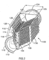
- Fluid treatment system 100 comprises an inlet 112 and an outlet 124. Fluid treatment system 100 further comprises a fluid treatment zone 120.
- Inlet 112 is interconnected to fluid treatment zone 120 by an inlet transition zone 114.
- Fluid outlet 124 is interconnected to fluid treatment zone 120 by an outlet transition zone 122.
- Inlet transition zone 114 comprises a first transition region 116 and an intermediate transition region 118.
- first bank 126 of radiation source assemblies Disposed in fluid treatment zone 120 is a first bank 126 of radiation source assemblies and a second bank 128 of radiation source assemblies.
- the orientation of the radiation source assemblies in banks 126 and 128 with respect to the direction of fluid flow through fluid treatment zone 120 is similar as that described above with respect to Figure 1 .
- each radiation source assembly in banks 126 and 128 is supported by a support post which is disposed transverse to: (i) the direction of fluid flow through fluid treatment zone 120, and (ii) the longitudinal axis of each radiation source assembly.
- a support post 134 is used for each column of radiation source assemblies in banks 126 and 128.
- the upstream end of the array of radiation sources comprises a column of radiation source assemblies from bank 126 connected to a support post 134 - i.e., there is no similar column of radiation source assemblies from bank 128 supported by the upstream centre support.
- This arrangement is reversed at a downstream support post 134a.
- each centre post serves the purpose of supporting a distal portion of radiation source assemblies from one column of each of banks 126 and 128.
- support post 134 also acts as a baffle, and likely will act as a protective shield behind which will be parked a cleaning device (described below).
- mounting sleeves 136 are cast or otherwise secured to the exterior surface of fluid treatment zone 120.
- the proximal region of each radiation source assembly is received in mounting sleeves 136 and a fluid type seal (not shown) can be achieved in a conventional manner.
- inlet 112 and outlet 124 can be. adapted to have a suitable standard flange element 113 and 125, respectively.
- flange elements 113 and 125 can be configured for conventional piping sizes between, for example, 30,5 cm (12 inches) and 182,9 cm (72 inches).
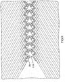
- banks 126 and 128 are arranged as an array of radiation source assemblies that present an obstruction which completely fills fluid treatment zone 120 when the fluid treatment zone 120 is viewed through inlet 112.
- the axis of each radiation source assembly can be seen by an observer looking along the direction of fluid flow through fluid treatment zone 120.
- This effect is created by partially staggering the orientation of radiation source assemblies in banks 126 and 128.
- FIG. 5 it can be seen that, proceeding lengthwise along fluid treatment zone 120, there is partial overlap of an upstream radiation source assembly with a downstream radiation source assembly in a successive manner - see, for example, lines 150 in Figure 5 which illustrate such a gradual staggering of radiation source assemblies in each of banks 126 and 128.
- a downstream radiation source assembly is partially exposed and partially obscured by an adjacent upstream radiation source assembly.
- the complete obstruction of the cross-sectional area the section of fluid treatment zone 120 (i.e., the section in which banks 126 and 128 are disposed) discussed above is not achieved by staggering of two successive columns of radiation source assemblies in banks 126 and 128 such that a downstream radiation source assembly fills the space between a pair of upstream radiation source assemblies. Rather, in this embodiment, three or more columns of such radiation source assemblies are oriented, in combination, to achieve the complete obstruction.
- each radiation source assembly preferably comprises of an elongate radiation source (e.g. an ultraviolet radiation lamp such as a low pressure high output ultraviolet radiation lamp) disposed within a protective sleeve (e.g. made from a radiation transparent material such as quartz and the like).
- a radiation source without a protective sleeve (e.g., photon emitting lamps without a protective sleeve).
- intermediate region 118 of inlet transition zone 114 has a transverse direction the same as fluid treatment zone 120.
- the sides of intermediate region 118 of inlet transition zone 114 are tapered as shown in Figure 4 . This arrangement allows for the tapering transition on the one hand while leaving adequate room for the apex of the array of radiation sources on the other hand.
- the radiation source assemblies in banks 126 and 128 have longitudinal axes which are angled with respect to the direction of fluid flow (arrow A) through fluid treatment zone 120.
- the result is an apex-shape orientation of radiation source assemblies in banks 126 and 128 as clearly seen in, for example, Figure 4 .
- the angle between the respective longitudinal axes of radiation source assemblies in banks 126 and 128 is preferably in the range of from about 15° to about 170°, more preferably from about 35° to about 120°, even more preferably from about 50° to about 120°, most preferably from about 60° to about 90°. It will be appreciated by those of skill in the art that, with a fixed length radiation source, the angle will determine the cross sectional area of the reactor. Further, although not illustrated specifically in the drawings herein, it is preferred and desirable to incorporate in the present fluid treatment system a cleaning device for removing fouling materials from the exterior of the radiation source assemblies in banks 126 and 128.
- FIG. 9 An example of incorporating a cleaning device in the present fluid treatment system is illustrated schematically in Figure 9 .
- the cleaning device as a sleeve which travels in a reciprocal manner over the exterior of the radiation source assemblies.
- a cleaning device 28 is provided for each radiation source assembly in the form of a movable sleeve.
- cleaning device 28 is "parked" such that it is downstream of support post 134.
- the nature of cleaning device 28 is not particularly restricted. See, for example, United States patent 6,342,188 [Pearcey et al. ] and 6,646,269 [Traubenberg et al. ], both assigned to the assignee of the present invention.
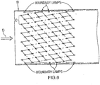
- FIG. 6 there is illustrated the side elevation, in schematic, of an arrangement of radiation source assemblies.
- this arrangement is the same as the N-shaped configuration discussed above.
- radiation source assemblies downstream of row B are arranged in a manner whereby more than two subsequent downstream vertical rows of radiation source assemblies are required to partially obscure pre-determined spacing C.
- pre-determined spacing C In other words, if one were to view the array of radiation source assemblies along arrow D the flow of fluid through pre-determined spacing C would be obstructed as a result of the arrangement of at least two rows of radiation source assemblies downstream of row B.
- the staggered radiation source assemblies per row can completely obstruct the line of vision through the staggered array whereas with fewer radiation source assemblies, the line of sight would not be completely obstructed.
- the array of radiation source assemblies includes a quartet of boundary lamps disposed in the same plain at the outer edges of the staggered array, in this embodiment, of the fluid treatment zone. As further illustrated, the array of radiation source assemblies is arranged to define repeating pattern consisting of a parallelogram containing four radiation source assemblies.
- Figure 7 illustrates a schematic similar to the one shown in Figure 6 with the exception that the staggering of the radiation source assemblies is different from that shown in Figure 6 . Specifically, it will be seen that the parallelogram repeating pattern referred to above with reference to Figure 6 does not appear in the arrangement shown in Figure 7 . Otherwise, Figure 7 does illustrate the use of boundary lamps and the staggering of subsequent rows of radiation source assemblies such that the gap between pairs of radiation source assemblies in the first row is effectively filled by more than two subsequent rows as one views the array of radiation source assemblies from one end of the fluid treatment zone.
- Figure 8a is a schematic similar to that shown in Figure 4 with the exception that two arrays 120a and 120b are used in the fluid treatment zone. As shown, each of array 120a and array 120b is a N-configuration similar to that shown in Figures 1-4 described above.
- Figure 8b is a schematic similar to that shown in Figure 4 with the exception that four arrays 120a, 120b, 120c and 120d are used in the fluid treatment zone.
- each of array 120a, 120b, 120c and 120d is a N-configuration similar to that shown in Figures 1-4 described above.
- each array 120a, 120b, 120c and 120d is arranged as described below with reference to Figure 16 .
- the spacing between adjacent arrays 120a, 120b, 120c and 120d is equal to the spacing between adjacent pairs lamps in a column of lamps in an array (e.g., dimension X in Figure 16 ).
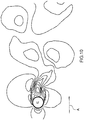
- a radiation source assembly E which is disposed such that its longitudinal axes is orthogonal to the direction of fluid flow shown by arrow A - such an orientation is known from the prior art.
- this orientation of radiation source assembly E presents a circular cross-section to the direction of fluid flow shown by arrow A. Consequently, vortices are generated downstream of radiation source assembly E which are random and wide-angled. The result of this is forced oscillation of radiation source assembly E and/or other radiation source assemblies in the vicinity of radiation source assembly E which can lead to breakage thereof.
- FIG 11 there is shown, in schematic, a radiation source assembly F orientated in the manner described above with reference to Figures 1-4 .
- radiation source assembly F presents an oval or ellipse cross-section to the direction of the flow of fluid depicted by arrow A. Consequently, vortices downstream of radiation source assembly F are more regular and less likely to create the forced oscillation disadvantages that can result in breakage of the radiation source assembly.
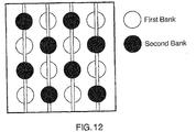
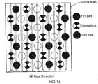
- FIGS 12-15 there is illustrated schematic end views (i.e., view thorough the fluid treatment zone) of a number of non-claimed arrangements of the staggered/parallel orientation referred to above.
- Figures 12-15 reference is made to "First”, “Second” and “Third” ( Figure 13-15 ) when describing a "Bank” of radiation source assemblies. These terms are intended to denote serial placement of a given "Bank” in a direction from an upstream portion to a downstream portion of the fluid treatment zone.
- the rows of radiation source assemblies in the "First Bank” are staggered in two respects: (i) there is a stagger with respect to a downstream (or upstream) "Second Bank” of radiation source assembles, and (ii) there is a stagger between adjacent rows of radiation source assemblies in the "First Bank”.
- the non-claimed arrangement of radiation source assemblies shown in Figure 12 is particularly well suited for application in fluid treatment systems such as those described in the Maarshalkerweerd #2 Patents.
- the arrangement of radiation source assemblies shown in Figure 13 is particularly well suited for application in open channel fluid treatment systems such as those described in the Maarshalkerweerd #1 Patents.
- the arrangement of radiation source assemblies comprises a First Bank, a Second Bank and a Third Bank. It will be seen that, in an end view, for an adjacent trio of rows of radiation source assemblies in the First Bank, the Second Bank and the Third Bank, each of the First Bank and the Third Bank is: (i) staggered with respect to the Second Bank, and (ii) non-staggered respect to the other.
- the resulting orientation of radiation may be characterized by: (i) an equilateral triangle though the axis of radiation source assemblies in adjacent rows of the same Bank, and (ii) an equilateral triangle though the axis of radiation source assemblies in an adjacent trio rows of the First Bank, the Second Bank and the Third Bank.
- FIG. 14 there are illustrated schematic views of non-claimed arrangements of radiation source assemblies similar to that discussed above with reference to Figure 13 .
- the positioning of rows is: First Bank followed by Second Bank followed by Third Bank.
- the positioning of rows is: Second Bank followed by Third Bank followed by First Bank.
- the positioning of rows is: Second Bank followed by First Bank followed by Third Bank.
- FIG 16 there is illustrated a highly preferred arrangement of radiation source assemblies for use in the present fluid treatment system.
- a schematic arrangement e.g., specific details support, electrical connection and sealing of the radiation source assemblies has been omitted for clarity
- FIG. 16 Each oval in Figure 16 denotes an opening in a wall of the fluid treatment system through which an end of the radiation soured assembly would emanate. It is preferred to arrange the radiation source assemblies in a manner such as illustrated above with reference to any of Figures 1-4 , 8a and 8b .
- a fluid treatment system 200 comprising, in a preferred embodiment, an enclosed (or closed) fluid treatment zone having a reactor ceiling 205 and a reactor floor 240. Disposed between reactor ceiling 205 and reactor floor 240 are four modules A, B, C and D of radiation source assemblies. Modules A, B. C and D are substantial the same. Those with skill in the art will appreciate that, while four modules are illustrated in Figure 16 , it is possible to use fewer or greater then four depending on the volume of fluid being treated, the quality of fluid being treated and other factors within the purview of a person skilled in the art.
- Each of modules A, B, C and D comprises four rows 210, 215, 220 and 225.
- rows 215 and 220 each comprise a series of radiation source assemblies where each adjacent pair of radiation source assemblies in each row are spaced apart in a substantially uniform manner. Specifically, the distance between all adjacent pairs of radiation source assemblies in row 215 is X as is the distance between all adjacent pairs of radiation source assemblies in row 220.
- rows 210 and 225 With reference to rows 210 and 225, it will be seen that most of the pairs of adjacent radiation source assemblies are equally spaced and, in a preferred embodiment, the spacing is X as shown with respect of rows 215 and 220. However, rows 210 and 225 also contain a pair of radiation source assemblies with a spacing Y that is less then spacing X used elsewhere in rows 210 and 225.
- a quartet of radiation source assemblies including a single radiation source assembly from each of rows 210, 215, 220 and 225 is arranged to define a parallelogram repeating unit E.
- Parallelogram repeating unit E comprises all of the radiation source assemblies in module A except the pair of boundary radiation source assemblies 230.
- parallelogram repeating pattern E it is possible to use parallelogram repeating pattern E to scale up or scale down module A (or one or more modules B-- C and D) depending on factors such as the volume of fluid being treated and the like .
- module A Another feature of module A is the so-called stagger order of the radiation source assemblies appearing in the parallelogram repeating unit E. As shown, progressing from reactor ceiling 205 to reactor floor 240, for a given parallelogram repeating pattern E, the following is the order of rows from which the radiation source assembly is derived: 210, 220, 215 and 225. In other words, for a given parallelogram repeating unit E, the sequence of rows progressing from an upstream portion of the fluid treatment zone to a downstream portion of the fluid treatment zone (i.e., 210, 215, 220 and 225) differs from the sequence of rows progressing from reactor ceiling 205 to reactor floor 240 (i.e., 210, 22.0, 215 and 225). This results in the parallelogram repeating unit E and provides advantageous in the ability to efficiently treat fluid passing through fluid treatment system 200.
- this so-called stagger order allows for scalability and modulation of the power used to operate the fluid treatment system.
- a stagger order such as parallelogram repeating pattern E
- a stagger order such as parallelogram repeating pattern E
- the spacing N between rows 210 and 215 is the same as the spacing between rows 220 and 225. It can be further seen that the spacing Z between rows 215 and 220 is greater that spacing V.
- spacing V and spacing Z may be substantially the same.
- spacing T there is a spacing T between adjacent modules A, B, C and D. It can be seen that spacing T is greater than spacing V. In certain cases, it may be desirable for spacing V and spacing T to be substantially the same.
- spacing V, spacing Z and spacing T may be substantially the same.
Landscapes
- Health & Medical Sciences (AREA)
- Life Sciences & Earth Sciences (AREA)
- Organic Chemistry (AREA)
- Hydrology & Water Resources (AREA)
- Engineering & Computer Science (AREA)
- Environmental & Geological Engineering (AREA)
- Water Supply & Treatment (AREA)
- Chemical & Material Sciences (AREA)
- Toxicology (AREA)
- Epidemiology (AREA)
- Animal Behavior & Ethology (AREA)
- General Health & Medical Sciences (AREA)
- Public Health (AREA)
- Veterinary Medicine (AREA)
- Physical Water Treatments (AREA)
- Physical Or Chemical Processes And Apparatus (AREA)
- Apparatus For Disinfection Or Sterilisation (AREA)
Description
- In one of its aspects, the present invention relates to a fluid treatment system, more particularly, an ultraviolet radiation water treatment system.
- Fluid treatment systems are generally known in the art. More particularly, ultraviolet (UN) radiation fluid treatment systems are generally known in the art. Early treatment systems comprised a fully enclosed chamber design containing one or more radiation (preferably UN) lamps. Certain problems existed with these earlier designs. These problems were manifested particularly when applied to large open flow treatment systems which are typical of larger scale municipal waste water or potable water treatment plants. Thus, these types of reactors had associated with them the following problems:
- relatively high capital cost of reactor;
- difficult accessibility to submerged reactor and/or wetted
equipment (lamps, sleeve cleaners, etc); - difficulties associated with removal of fouling materials
from fluid treatment equipment; - relatively low fluid disinfection efficiency, and/or
- full redundancy of equipment was required for maintenance of wetted components (sleeves, lamps and the like).
- The shortcomings in conventional closed reactors led to the development of the so-called "open channel" reactors.
- In Egberts, G, et al, "DER EINSATZ DER UV-BESTRAHLUNG ZUR KEIMZAHLREDUZIERUNG IM BIOLOGISCH GEREINIGTEN ABWASSER", KORRESPONDENZ ABWASSER, ABWASSERTECHNISCHE VEREINIGUNG, ST. AUGUSTIN, DE, discloses aspects relating to the construction of open channel fluid treatment systems in the context of a recently developed long-life UV lamp and arrangements for the use thereof.
- For example, United States patents
4,482,809 4,872,980 5,006,244 - Such systems include an array of UN lamp modules (e.g., frames) which include several UN lamps each of which are mounted within sleeves which extend between and are supported by a pair of legs which are attached to a cross-piece. The so-supported sleeves (containing the UN lamps) are immersed into a fluid to be treated which is then irradiated as required. The amount of radiation to which the fluid is exposed is determined by the proximity of the fluid to the lamps, the output wattage of the lamps and the flow rate of the fluid past the lamps. Typically, one or more UN sensors may be employed to monitor the UV output of the lamps and the fluid level is typically controlled, to some extent, downstream of the treatment device by means of level gates or the like.
- The Maarschalkerweerd #1 Patents teach fluid treatment systems which were characterized by improved ability to extract the equipment from a wetted or submerged state without the need for full equipment redundancy. These designs compartmentalized the lamp arrays into rows and/or columns and were characterized by having the top of the reactor open to provide free-surface flow of fluid in a "top open" channel.
- The fluid treatment system taught in the Maarschalkerweerd #1 Patents is characterized by having a free-surface flow of fluid (typically the top fluid surface was not purposely controlled or constrained). Thus, the systems would typically follow the behaviour of open channel hydraulics. Since the design of the system inherently comprised a free-surface flow of fluid, there were constraints on the maximum flow each lamp or lamp array could handle before either one or other hydraulically adjoined arrays would be adversely affected by changes in water elevation. At higher flows or significant changes in the flow, the unrestrained or free-surface flow of fluid would be allowed to change the treatment volume and cross-sectional shape of the fluid flow, thereby rendering the reactor relatively ineffective. Provided that the power to each lamp in the array was relatively low, the subsequent fluid flow per lamp would be relatively low. The concept of a fully open channel fluid treatment system would suffice in these lower lamp power and subsequently lower hydraulically loaded treatment systems. The problem here was that, with less powerful lamps, a relatively large number of lamps was required to treat the same volume of fluid flow. Thus, the inherent cost of the system would be unduly large and/or not competitive with the additional features of automatic lamp sleeve cleaning and large fluid volume treatment systems.
- This led to the so-called "semi-enclosed" fluid treatment systems.
- United States patents
5,418,370 ,5,539,210 andRe36,896 (all in the name of Maarschalkerweerd and all assigned to the assignee of the present invention and hereinafter referred to as the Maarschalkerweerd #2 Patents) all describe an improved radiation source module for use in gravity fed fluid treatment systems which employ UV radiation. Generally, the improved radiation source module comprises a radiation source assembly (typically comprising a radiation source and a protective (e.g., quartz) sleeve) sealingly cantilevered from a support member. The support member may further comprise appropriate means to secure the radiation source module in the gravity fed fluid treatment system. - Thus, in order to address the problem of having a large number of lamps and the incremental high cost of cleaning associated with each lamp, higher output lamps were applied for UV fluid treatment. The result was that the number of lamps and subsequent length of each lamp was dramatically reduced. This led to commercial affordability of automatic lamp sleeve cleaning equipment, reduced space requirements for the treatment system and other benefits. In order to use the more powerful lamps (e.g. medium pressure UN lamps), the hydraulic loading per lamp during use of the system would be increased to an extent that the treatment volume/cross-sectional area of the fluid in the reactor would significantly change if the reactor surface was not confined on all surfaces, and hence such a system would be rendered relatively ineffective. Thus, the Maarschalkerweerd #2 Patents are characterized by having a closed surface confining the fluid being treated in the treatment area of the reactor. This closed treatment system had open ends which, in effect, were disposed in an open channel. The submerged or wetted equipment (UN lamps, cleaners and the like) could be extracted using pivoted hinges, sliders and various other devices allowing removal of equipment from the semi-enclosed reactor to the free surfaces.
- The fluid treatment system described in the Maarschalkerweerd #2 Patents was typically characterized by relatively short length lamps which were cantilevered to a substantially vertical support arm (i.e., the lamps were supported at one end only). This allowed for pivoting or other extraction of the lamp from the semi-enclosed reactor. These significantly shorter and more powerful lamps inherently are characterized by being less efficient in converting electrical energy to UN energy. The cost associated with the equipment necessary to physically access and support these lamps was significant.
- Historically, the fluid treatment modules and systems described in the Maarschalkerweerd #1 and #2 Patents have found widespread application in the field of municipal waste water treatment (i.e., treatment of water that is discharged to a river, pond, lake or other such receiving stream).
- In the field of municipal drinking water, it is known to utilize so-called "closed" fluid treatment systems or "pressurized" fluid treatment systems.
- Closed fluid treatment devices are known - see, for example, United States patent
5,504,335 (Maarschalkerweerd #3). Maarschalkerweerd #3 teaches a closed fluid treatment device comprising a housing for receiving a flow of fluid. The housing comprises a fluid inlet, a fluid outlet, a fluid treatment zone disposed between the fluid inlet and the fluid outlet, and at least one radiation source module disposed in the fluid treatment zone. The fluid inlet, the fluid outlet and the fluid treatment zone are in a collinear relationship with respect to one another. The at least one radiation source module comprises a radiation source sealably connected to a leg which is sealably mounted to the housing. The radiation source is disposed substantially parallel to the flow of fluid. The radiation source module is removable through an aperture provided in the housing intermediate to fluid inlet and the fluid outlet thereby obviating the need to physically remove the device for service of the radiation source. - United States patent
6,500,346 [Taghipour et al. (Taghipour)] also teaches a closed fluid treatment device, particularly useful for ultraviolet radiation treatment of fluids such as water. The device comprises a housing for receiving a flow of fluid. The housing has a fluid inlet, a fluid outlet, a fluid treatment zone disposed between the fluid inlet and the fluid outlet and at least one radiation source having a longitudinal axis disposed in the fluid treatment zone substantially transverse to a direction of the flow of fluid through the housing. The fluid inlet, the fluid outlet and the fluid treatment zone are arranged substantially collinearly with respect to one another. The fluid inlet has a first opening having: (i) a cross-sectional area less than a cross-sectional area of the fluid treatment zone, and (ii) a largest diameter substantially parallel to the longitudinal axis of the at least one radiation source assembly. - Practical implementation of known fluid treatment systems of the type described above have been such that the longitudinal axis of the radiation source is: (i) parallel to the direction of fluid flow through the fluid treatment system, or (ii) orthogonal to the direction of fluid flow through the fluid treatment system. Further, in arrangement (ii), it has been common to place the lamps in an array such that, from an upstream end to a downstream end of the fluid treatment system, a downstream radiation source is placed directly behind an upstream radiation source.
- The use of arrangement (ii) in an UN radiation water treatment system has been based on the theory that radiation was effective up to a prescribed distance from the radiation source, depending on the transmittance of the water being treated. Thus, it has become commonplace to interspace the radiation sources in arrangement (ii) such that the longitudinal axes of adjacent radiation sources are spaced at a distance equal to approximately twice the prescribed distance mentioned in the previous sentence.
- Unfortunately, for the treatment of large volumes of fluid, arrangement (ii) can be disadvantageous for a number of reasons. Specifically, implementation of arrangement (ii) requires a relatively large "footprint" or space to house the radiation sources. Further, the use of a large number of radiation sources in arrangement (ii) creates a relatively large coefficient of drag resulting in a relatively large hydraulic pressure loss/gradient over the length of the fluid treatment system. Still further, the use of a large number of radiation sources in arrangement (ii) can produce vortex effects (these effects are discussed in more detail hereinbelow) resulting in forced oscillation of the radiation sources - such forced oscillation increases the likelihood of breakage of the radiation source and/or protective sleeve (if present).
- Accordingly, there remains a need in the art for a fluid treatment system, particularly a closed fluid treatment system which has one or more of the following features:
- it can treat large volumes of fluid (e.g., wastewater or drinking water and the like);
- it can increase the limit of the maximum admissible velocity through the reactor;
- it requires a relatively small "footprint";
- it results in a relatively lower coefficient of drag resulting in an improved hydraulic pressure loss/gradient over the length of the fluid treatment system;
- it results in relatively lower (or no) forced oscillation of the radiation sources thereby obviating or mitigating breakage of the radiation source and/or protective sleeve (if present);
- it can be readily adapted to make use of relatively recently developed so- called "low pressure high output" (LPHO), amalgam and/or other UN emitting lamps while allowing for ready extraction of the lamps from the fluid treatment system for servicing and the like;
- it can employ a lamp of a standard length for varying widths of reactors;
- it can be readily combined with a cleaning system for removing fouling materials from the exterior of the radiation source(s);
- it can be readily installed in a retrofit manner in an existing fluid treatment plant; and
- it provides relatively improved disinfection performance compared to conventional fluid treatment systems.
- It is an object of the present invention to provide a novel fluid treatment system which obviates or mitigates at least one of the above-mentioned disadvantages of the prior art.
- This is obtained by a fluid treatment system having the features disclosed in claim 1. The dependent claims outline advantageous forms of embodiment of this system.
- Thus, the present inventors have discovered a fluid treatment system having one or more of the following advantages:
- it can treat large volumes of fluid (e.g., wastewater, drinking water or the like);
- it can increase the limit of the maximum admissible velocity through the reactor;
- it requires a relatively small "footprint";
- it results in a relatively lower coefficient of drag resulting in an improved hydraulic pressure loss/gradient over the length of the fluid treatment system;
- it results in relatively lower (or no) forced oscillation of the radiation sources thereby obviating or mitigating of breakage of the radiation source and/or protective sleeve (if present);
- it can be readily adapted to make use of low pressure ultraviolet emitting lamps and relatively recently developed so-called "low pressure high output" (LPHO), amalgam and/or other ultraviolet radiation and photon emitting lamps while allowing for ready extraction of the lamps from the fluid treatment system for servicing and the like;
- it can employ a lamp of standard length for varying widths of reactors simply by varying the oblique angle between the lamps;
- it can be readily combined with a cleaning system for removing fouling materials from the exterior of the radiation source(s);
- it can be readily installed in a retrofit manner in an existing fluid treatment plant; and
- it provides relatively improved disinfection performance compared to conventional fluid treatment systems (e.g., systems in which the radiation source is disposed such that its longitudinal axis is parallel or orthogonal to the direction of fluid flow through the fluid treatment zone contained within the system).
- The present invention relates to a fluid treatment system according to claim 1 wherein the radiation source assemblies are arranged oblique to the direction of fluid flow through the fluid treatment zone as a series of rows, each row comprising a plurality of radiation sources assemblies spaced apart in a direction orthogonal to the direction of fluid flow through the fluid treatment zone.
- In one embodiment of this aspect of the invention (also referred to as the "staggered/oblique orientation"), the radiation source assemblies are arranged oblique to the direction of fluid flow through the fluid treatment zone and oriented in a manner whereby, from an upstream portion to a downstream portion of the fluid treatment zone, the radiation source assemblies are staggered in a direction orthogonal to a direction of fluid flow through the fluid treatment zone to define partial overlap between these assemblies. The collection of assemblies is arranged such that a flow of fluid has no unobstructed path through the arrangement of radiation source assemblies in the fluid treatment zone. Practically, one may envision this by viewing the inlet of the fluid treatment zone and seeing no clear, unobstructed path through the arrangement of radiation source assemblies in the fluid treatment zone from the inlet to the outlet.
- In another of its aspects, the present invention relates to a fluid treatment system in which an array of radiation source assemblies are arranged in the fluid treatment zone. The radiation source assemblies are oriented oblique to the direction of fluid flow through the fluid treatment zone. The array of radiation source assemblies includes a first row of radiation source assemblies arranged to define a predetermined spacing between pairs of radiation source assemblies in the row in a direction orthogonal to the direction of fluid flow through the fluid treatment zone. At least two further rows of radiation source assemblies are disposed downstream of the first row of radiation source assemblies.
- In one preferred embodiment, these downstream rows of radiation source assemblies (i.e., two or more of such rows) combine to fill or occupy the pre-determined spacing between pairs of radiation source assemblies within the column of lamps in the first row - i.e., if one were to view the array of radiation source assemblies from the inlet of the fluid treatment system.
- In the present fluid treatment system, it is possible to incorporate a so-called transition region upstream and/or downstream of the fluid treatment zone. Preferably, such a transition region serves to funnel or otherwise transition the flow of fluid in a manner such that cross-sectional area of the flow of fluid orthogonal to the direction of fluid flow is: (i) increased (if the transition region is placed upstream of the fluid treatment zone) thereby decreasing fluid flow velocity, or (ii) decreased (if the transition region is placed downstream of the fluid treatment zone) thereby increasing fluid flow velocity.
- Throughout the specification, reference is made to terms such as "closed zone", "closed cross-section" and "constrained". In essence, these terms are used interchangeably and are intended to encompass a structure which effectively surrounds the fluid flow in a manner similar to that described in the Maarschalkerweerd #2 Patents (with particular reference to the fluid treatment zone described therein).
- Further, as used throughout this specification, the term "fluid" is intended to have a broad meaning and encompasses liquids and gases. The preferred fluid for treatment with the present system is a liquid, preferably water (e.g., wastewater, industrial effluent, reuse water, potable water, ground water and the like). Still further, the terms "rows" and "columns" are used throughout this specification in relation to arrangements of radiation sources and it is to be understood that these terms are used interchangeably.
- Those with skill in the art will recognize that there is reference throughout the specification to the use of seals and the like to provide a practical fluid seal between adjacent elements in the fluid treatment system. For example, those of skill in the art will recognize that it is well known in the art to use combinations of coupling nuts, O-rings, bushings and like to provide a substantially fluid tight seal between the exterior of a radiation source assembly (e.g., water) and the interior of a radiation source assembly containing the radiation source (e.g., an ultraviolet radiation lamp).
- Embodiments of the present invention will be described with reference to the accompanying drawings, wherein like numerals designate like elements, and in which:
-
Figure 1 illustrates, in perspective view, partially cutaway, a schematic of a first embodiment of the present fluid treatment system; -
Figure 2 illustrates a perspective view, partially cutaway of a second embodiment of the present fluid treatment system; -
Figure 3 illustrates an end view from the inlet of the fluid treatment system illustrated inFigure 2 ; -
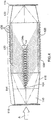
Figure 4 illustrates a top view (partially cutaway) of the fluid treatment system illustrated inFigure 2 ; -
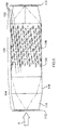
Figure 5 illustrates a side elevation of the fluid treatment system illustrated inFigure 2 ; -
Figure 6 illustrates a schematic side elevation of orientation of radiation source assemblies in a third embodiment of the present fluid treatment system; -
Figure 7 illustrates a schematic side elevation of orientation of radiation source assemblies in a fourth embodiment of the present fluid treatment system; -
Figure 8 a illustrates a top view (partially cutaway) of a fifth embodiment of the present fluid treatment system; -
Figure 8b illustrates a top view (partially cutaway) of a sixth embodiment of the present fluid treatment system; -
Figure 9 illustrates a top view of an array of radiation source assemblies incorporating a cleaning device for removing fouling materials from the exterior of the assemblies; -
Figure 10 illustrates vortices generated as fluid flows passes a radiation source assembly of a prior art fluid treatment system; -
Figure 11 illustrates vortices generated as fluid flows passes a radiation source assembly of a fluid treatment system in accordance with the present invention; -
Figures 12-15 , there is illustrated schematic end views (i.e., viewed through the fluid treatment zone) of a number of non-claimed arrangements of the staggered/parallel orientation referred to above; and -
Figure 16 illustrates a schematic side elevation of orientation of radiation source assemblies in a highly preferred embodiment of the present fluid treatment system. - With reference to
Figure 1 , there is illustrated afluid treatment system 10.Fluid treatment system 10 comprises aninlet 12 and anoutlet 24. Disposed betweeninlet 12 andoutlet 24 is afluid treatment zone 20. -
Fluid treatment zone 20 is interconnected toinlet 12 by aninlet transition zone 14 comprising afirst transition region 16 andintermediate transition region 18.Outlet 24 is interconnected tofluid treatment zone 20 by anoutlet transition zone 22. - As illustrated, fluid passes through fluid treatment system 10 (including fluid treatment zone 20) in the direction of arrow A.
- As shown, each of
inlet 12,inlet transition zone 14,fluid treatment zone 20,outlet transition zone 22 andoutlet 24 have a closed cross-section. The use of the term "closed cross-section" is intended to mean an enclosure which bounds a flow of fluid on all sides and/or surfaces. - As shown,
inlet 12 andoutlet 24 have a circular cross-section much like a conventional pipe arrangement. As further illustrated,fluid treatment zone 20 has a square or rectangular cross-section. Of course it is possible to configurefluid treatment zone 20 to have other cross-sectional shapes. - Disposed in
fluid treatment zone 20 is afirst bank 26 of radiation source assemblies and asecond bank 28 of radiation source assemblies. Each radiation source assembly inbanks fluid treatment zone 20. - The radiation source assemblies in
bank 26 are mounted on one side offluid treatment zone 20 and have a distal end thereof supported by asupport element 32. Similarly, each radiation source assembly inbank 28 has one end mounted on a side offluid treatment zone 20 and a distal end thereof supported bysupport element 32. - In the result, the array of radiation source assemblies presented by
banks - Further, while the distal end of each radiation source assembly in
banks single support element 32, other support elements will be apparent of those of skill in the art. - As shown,
intermediate transition region 18 serves the purpose of providing a nesting region for the apex of the array of lamps. As such, it is preferred to have the sides ofintermediate transition region 18 tapered to a smaller dimension while, in the illustrated embodiment, maintaining the top and bottom at a consistent dimension (this will be discussed further below). -
First transition region 16 interconnectsintermediate transition region 18 andinlet 12, and serves the purpose of: (i) reducing the dimension of the enclosure, and (ii) transitioning the cross-section shape from a polygon to a circle. Similarly,outlet transition zone 22 serves to reduce the dimension of the enclosure and transition the cross-sectional shape of the enclosure from a circle to a polygon. - The use of
inlet transition zone 14 andoutlet transition zone 22 also serves to obviate or mitigate hydraulic head loss problems that might occur if dramatic changes in dimensions of the enclosure were cast into the system. - A second embodiment of the present fluid treatment system will now be discussed with reference to
Figures 2-5 . InFigures 2-5 , elements having the same last two digits as elements appearing inFigure 1 are attended to denote like elements. - With reference to
Figures 2-5 , there is illustrated afluid treatment system 100.Fluid treatment system 100 comprises aninlet 112 and anoutlet 124.Fluid treatment system 100 further comprises afluid treatment zone 120. -
Inlet 112 is interconnected tofluid treatment zone 120 by aninlet transition zone 114.Fluid outlet 124 is interconnected tofluid treatment zone 120 by anoutlet transition zone 122.Inlet transition zone 114 comprises afirst transition region 116 and anintermediate transition region 118. - Disposed in
fluid treatment zone 120 is afirst bank 126 of radiation source assemblies and asecond bank 128 of radiation source assemblies. The orientation of the radiation source assemblies inbanks fluid treatment zone 120 is similar as that described above with respect toFigure 1 . - As shown, the distal portion of each radiation source assembly in
banks fluid treatment zone 120, and (ii) the longitudinal axis of each radiation source assembly. - As shown, particularly with respect to
Figure 4 , asupport post 134 is used for each column of radiation source assemblies inbanks Figure 4 , the upstream end of the array of radiation sources comprises a column of radiation source assemblies frombank 126 connected to a support post 134 - i.e., there is no similar column of radiation source assemblies frombank 128 supported by the upstream centre support. This arrangement is reversed at adownstream support post 134a. Otherwise, each centre post serves the purpose of supporting a distal portion of radiation source assemblies from one column of each ofbanks post 134 also acts as a baffle, and likely will act as a protective shield behind which will be parked a cleaning device (described below). - With particular reference to
Figures 2 and5 , it can be seen that mountingsleeves 136 are cast or otherwise secured to the exterior surface offluid treatment zone 120. The proximal region of each radiation source assembly is received in mountingsleeves 136 and a fluid type seal (not shown) can be achieved in a conventional manner. - As further illustrated in
Figures 2-5 ,inlet 112 andoutlet 124 can be. adapted to have a suitablestandard flange element fluid treatment system 100 in conventional piping. For example, it is possible forflange elements - With particular reference to
Figure 3 , it will be seen thatbanks fluid treatment zone 120 when thefluid treatment zone 120 is viewed throughinlet 112. In other words, there is no apparent path by which fluid can pass throughfluid treatment zone 120 without being forced to detour around a radiation source assembly inbanks 126 and/or 128. This being the case, the axis of each radiation source assembly can be seen by an observer looking along the direction of fluid flow throughfluid treatment zone 120. - This effect is created by partially staggering the orientation of radiation source assemblies in
banks Figure 5 , it can be seen that, proceeding lengthwise alongfluid treatment zone 120, there is partial overlap of an upstream radiation source assembly with a downstream radiation source assembly in a successive manner - see, for example,lines 150 inFigure 5 which illustrate such a gradual staggering of radiation source assemblies in each ofbanks - Thus, it can be seen that the complete obstruction of the cross-sectional area the section of fluid treatment zone 120 (i.e., the section in which
banks banks - Preferably, each radiation source assembly preferably comprises of an elongate radiation source (e.g. an ultraviolet radiation lamp such as a low pressure high output ultraviolet radiation lamp) disposed within a protective sleeve (e.g. made from a radiation transparent material such as quartz and the like). In some case it may be possible (and preferred) to utilize a radiation source without a protective sleeve (e.g., photon emitting lamps without a protective sleeve).
- As can be seen, particularly with reference to
Figure 5 ,intermediate region 118 ofinlet transition zone 114 has a transverse direction the same asfluid treatment zone 120. The sides ofintermediate region 118 ofinlet transition zone 114 are tapered as shown inFigure 4 . This arrangement allows for the tapering transition on the one hand while leaving adequate room for the apex of the array of radiation sources on the other hand. - The radiation source assemblies in
banks fluid treatment zone 120. The result is an apex-shape orientation of radiation source assemblies inbanks Figure 4 . The angle between the respective longitudinal axes of radiation source assemblies inbanks banks - An example of incorporating a cleaning device in the present fluid treatment system is illustrated schematically in
Figure 9 . As shown, it is possible to incorporate the cleaning device as a sleeve which travels in a reciprocal manner over the exterior of the radiation source assemblies. As shown, acleaning device 28 is provided for each radiation source assembly in the form of a movable sleeve. In the illustrated embodiment, cleaningdevice 28 is "parked" such that it is downstream ofsupport post 134. The nature ofcleaning device 28 is not particularly restricted. See, for example, United States patent6,342,188 [Pearcey et al. ] and6,646,269 [Traubenberg et al. ], both assigned to the assignee of the present invention. - With reference to
Figure 6 , there is illustrated the side elevation, in schematic, of an arrangement of radiation source assemblies. Generally, this arrangement is the same as the N-shaped configuration discussed above. As shown, there is a row B of 6 radiation source assemblies disposed vertically in the fluid treatment zone. Between each pair of radiation source assemblies in row B, there is a pre-determined spacing' C. - As illustrated, radiation source assemblies downstream of row B are arranged in a manner whereby more than two subsequent downstream vertical rows of radiation source assemblies are required to partially obscure pre-determined spacing C. In other words, if one were to view the array of radiation source assemblies along arrow D the flow of fluid through pre-determined spacing C would be obstructed as a result of the arrangement of at least two rows of radiation source assemblies downstream of row B. It will be appreciated by those of skill in the art that, with a relatively large enough number of rows B, the staggered radiation source assemblies per row can completely obstruct the line of vision through the staggered array whereas with fewer radiation source assemblies, the line of sight would not be completely obstructed.
- As shown, the array of radiation source assemblies includes a quartet of boundary lamps disposed in the same plain at the outer edges of the staggered array, in this embodiment, of the fluid treatment zone. As further illustrated, the array of radiation source assemblies is arranged to define repeating pattern consisting of a parallelogram containing four radiation source assemblies.
-
Figure 7 illustrates a schematic similar to the one shown inFigure 6 with the exception that the staggering of the radiation source assemblies is different from that shown inFigure 6 . Specifically, it will be seen that the parallelogram repeating pattern referred to above with reference toFigure 6 does not appear in the arrangement shown inFigure 7 . Otherwise,Figure 7 does illustrate the use of boundary lamps and the staggering of subsequent rows of radiation source assemblies such that the gap between pairs of radiation source assemblies in the first row is effectively filled by more than two subsequent rows as one views the array of radiation source assemblies from one end of the fluid treatment zone. -
Figure 8a is a schematic similar to that shown inFigure 4 with the exception that twoarrays array 120a andarray 120b is a N-configuration similar to that shown inFigures 1-4 described above. -
Figure 8b is a schematic similar to that shown inFigure 4 with the exception that fourarrays array Figures 1-4 described above. Preferably, eacharray Figure 16 . hiFigure 8b , it is preferred that the spacing betweenadjacent arrays Figure 16 ). - With reference to
Figure 10 , there is shown, in schematic, a radiation source assembly E which is disposed such that its longitudinal axes is orthogonal to the direction of fluid flow shown by arrow A - such an orientation is known from the prior art. As will be understood by those of skill in the art, this orientation of radiation source assembly E presents a circular cross-section to the direction of fluid flow shown by arrow A. Consequently, vortices are generated downstream of radiation source assembly E which are random and wide-angled. The result of this is forced oscillation of radiation source assembly E and/or other radiation source assemblies in the vicinity of radiation source assembly E which can lead to breakage thereof. - With reference to
Figure 11 , there is shown, in schematic, a radiation source assembly F orientated in the manner described above with reference toFigures 1-4 . In this orientation, radiation source assembly F presents an oval or ellipse cross-section to the direction of the flow of fluid depicted by arrow A. Consequently, vortices downstream of radiation source assembly F are more regular and less likely to create the forced oscillation disadvantages that can result in breakage of the radiation source assembly. - With reference to
Figures 12-15 , there is illustrated schematic end views (i.e., view thorough the fluid treatment zone) of a number of non-claimed arrangements of the staggered/parallel orientation referred to above. InFigures 12-15 , reference is made to "First", "Second" and "Third" (Figure 13-15 ) when describing a "Bank" of radiation source assemblies. These terms are intended to denote serial placement of a given "Bank" in a direction from an upstream portion to a downstream portion of the fluid treatment zone. - Thus, with reference to
Figure 12 , it will be seen that the rows of radiation source assemblies in the "First Bank" are staggered in two respects: (i) there is a stagger with respect to a downstream (or upstream) "Second Bank" of radiation source assembles, and (ii) there is a stagger between adjacent rows of radiation source assemblies in the "First Bank". The non-claimed arrangement of radiation source assemblies shown inFigure 12 is particularly well suited for application in fluid treatment systems such as those described in the Maarshalkerweerd #2 Patents. - With reference to
Figure 13 , there is illustrated another schematic non-claimed arrangement of radiation source assemblies in accordance with the staggered/parallel orientation referred to above. The arrangement of radiation source assemblies shown inFigure 13 is particularly well suited for application in open channel fluid treatment systems such as those described in the Maarshalkerweerd #1 Patents. As shown, the arrangement of radiation source assemblies comprises a First Bank, a Second Bank and a Third Bank. It will be seen that, in an end view, for an adjacent trio of rows of radiation source assemblies in the First Bank, the Second Bank and the Third Bank, each of the First Bank and the Third Bank is: (i) staggered with respect to the Second Bank, and (ii) non-staggered respect to the other. The resulting orientation of radiation may be characterized by: (i) an equilateral triangle though the axis of radiation source assemblies in adjacent rows of the same Bank, and (ii) an equilateral triangle though the axis of radiation source assemblies in an adjacent trio rows of the First Bank, the Second Bank and the Third Bank. - With reference to
Figures 14 and15 , there are illustrated schematic views of non-claimed arrangements of radiation source assemblies similar to that discussed above with reference toFigure 13 . hiFigure 13 , from the left hand reactor wall, the positioning of rows is: First Bank followed by Second Bank followed by Third Bank. InFigure 14 , from the left hand reactor wall, the positioning of rows is: Second Bank followed by Third Bank followed by First Bank. InFigure 15 , from the left hand reactor wall, the positioning of rows is: Second Bank followed by First Bank followed by Third Bank. - With reference to
Figure 16 , there is illustrated a highly preferred arrangement of radiation source assemblies for use in the present fluid treatment system. Thus, inFigure 16 , there is illustrated a schematic arrangement (e.g., specific details support, electrical connection and sealing of the radiation source assemblies has been omitted for clarity) of the radiation source assemblies shown in a side elevation of the fluid treatment system. Each oval inFigure 16 denotes an opening in a wall of the fluid treatment system through which an end of the radiation soured assembly would emanate. It is preferred to arrange the radiation source assemblies in a manner such as illustrated above with reference to any ofFigures 1-4 ,8a and8b . - With continued reference to
Figure 16 , there is illustrated afluid treatment system 200 comprising, in a preferred embodiment, an enclosed (or closed) fluid treatment zone having areactor ceiling 205 and areactor floor 240. Disposed betweenreactor ceiling 205 andreactor floor 240 are four modules A, B, C and D of radiation source assemblies. Modules A, B. C and D are substantial the same. Those with skill in the art will appreciate that, while four modules are illustrated inFigure 16 , it is possible to use fewer or greater then four depending on the volume of fluid being treated, the quality of fluid being treated and other factors within the purview of a person skilled in the art. - Each of modules A, B, C and D comprises four
rows rows row 215 is X as is the distance between all adjacent pairs of radiation source assemblies inrow 220. - With reference to
rows rows rows rows - As will be seen with reference to module A, a quartet of radiation source assemblies including a single radiation source assembly from each of
rows radiation source assemblies 230. Those with skill in the art will appreciate that it is possible to use parallelogram repeating pattern E to scale up or scale down module A (or one or more modules B-- C and D) depending on factors such as the volume of fluid being treated and the like . - Another feature of module A is the so-called stagger order of the radiation source assemblies appearing in the parallelogram repeating unit E. As shown, progressing from
reactor ceiling 205 toreactor floor 240, for a given parallelogram repeating pattern E, the following is the order of rows from which the radiation source assembly is derived: 210, 220, 215 and 225. In other words, for a given parallelogram repeating unit E, the sequence of rows progressing from an upstream portion of the fluid treatment zone to a downstream portion of the fluid treatment zone (i.e., 210, 215, 220 and 225) differs from the sequence of rows progressing fromreactor ceiling 205 to reactor floor 240 (i.e., 210, 22.0, 215 and 225). This results in the parallelogram repeating unit E and provides advantageous in the ability to efficiently treat fluid passing throughfluid treatment system 200. - Specifically, this so-called stagger order allows for scalability and modulation of the power used to operate the fluid treatment system. By this it is meant that, using a stagger order such as parallelogram repeating pattern E, it is possible to lower the power consumption or even turn off of the power to certain rows of radiation source assemblies within a given module (e.g., one, some or all of modules A, B, C and D) to account for factors such as fluid transmittance, type and/or concentration of a particular contaminant and the like. For example, it is possible to operate the radiation source assemblies in
rows rows - Such fine tuning would be difficult to achieve if the sequence of rows progressing from an upstream portion of the fluid treatment zone to a downstream portion of the fluid treatment zone (i.e., 210, 220, 21 5 and 225) was the same as the sequence of rows progressing from
reactor ceiling 205 to reactor floor 240 (i.e., 210, 215, 220 and 225). In this situation, to modify power consumption, it would be necessary to turn off entire modules within the fluid treatment zone resulting in relatively uneven fluid treatment. - With further reference to
Figure 16 , it can be seen that the spacing N betweenrows rows rows - In certain cases, it may be desirable for spacing V and spacing Z to be substantially the same.
- Still further, there is a spacing T between adjacent modules A, B, C and D. It can be seen that spacing T is greater than spacing V. In certain cases, it may be desirable for spacing V and spacing T to be substantially the same.
- Further, in certain cases, it may be desirable for spacing V, spacing Z and spacing T to be substantially the same.
- While this invention has been described with reference to illustrative embodiments and examples, the description is not intended to be construed in a limiting sense. Thus, various modifications of the illustrative embodiments, as well as other embodiments of the invention, will be apparent to persons skilled in the art upon reference to this description.
Claims (6)
- A fluid treatment system (10; 100) comprising:an inlet (12; 112);an outlet (14; 114);a fluid treatment zone (20; 120) disposed between the inlet and the outlet, the fluid treatment zone having disposed therein an array of rows of radiation source assemblies;each radiation source assembly having a longitudinal axis oblique to a direction of fluid flow through the fluid treatment zone;each row comprising a plurality of radiation source assemblies in spaced relation in a direction transverse to the direction of fluid flow through the fluid treatment zone to define a gap through which fluid may flow between an adjacent pair of radiation source assemblies;all rows in the array being staggered with respect to one another in a direction orthogonal to the direction of fluid flow through the fluid treatment zone such that the gap between an adjacent pair of radiation source assemblies in an upstream row of radiation source assemblies is completely obstructed in the direction of fluid flow, and no clear, unobstructed path through the arrangement of radiation source assemblies in the fluid treatment zone form the inlet to the outlet is seen when viewing the inlet of the fluid treatment zone, by at least two serially disposed downstream rows of radiation source assemblies.
- The fluid treatment system defined in Claim 1, wherein the array comprises from three to twenty rows of radiation source assemblies.
- The fluid treatment system defined in any one of Claims 1-2, wherein the fluid treatment zone comprises an open cross-section or an enclosure having a closed cross-section.
- The fluid treatment system defined in any one of Claims 1-3, further comprising a first transition zone (16; 116) interposed between the inlet and the fluid treatment zone, the first transition zone having a varying dimension orthogonal to the direction of fluid flow through the fluid treatment zone.
- The fluid treatment system defined in Claim 4, further comprising a second transition zone (22; 122) interposed between the fluid zone and the outlet, the second transition zone having a varying dimension orthogonal to the direction of fluid flow through the fluid treatment zone.
- The fluid treatment system defined in Claim 5, wherein at least one of the first transition zone and the second transition zone comprises an intermediate transition region (18; 118) juxtaposed to the fluid treatment zone, the intermediate transition region having a varying dimension in first direction orthogonal to the direction of fluid flow through the fluid treatment zone and constant dimension in a second direction orthogonal to the first direction.
Applications Claiming Priority (4)
| Application Number | Priority Date | Filing Date | Title |
|---|---|---|---|
| US55218504P | 2004-03-12 | 2004-03-12 | |
| US61321504P | 2004-09-28 | 2004-09-28 | |
| PCT/CA2005/000375 WO2005087277A1 (en) | 2004-03-12 | 2005-03-14 | Fluid treatment system |
| EP05714615A EP1737501A4 (en) | 2004-03-12 | 2005-03-14 | FLUID TREATMENT SYSTEM |
Related Parent Applications (1)
| Application Number | Title | Priority Date | Filing Date |
|---|---|---|---|
| EP05714615A Division EP1737501A4 (en) | 2004-03-12 | 2005-03-14 | FLUID TREATMENT SYSTEM |
Publications (2)
| Publication Number | Publication Date |
|---|---|
| EP3111963A1 EP3111963A1 (en) | 2017-01-04 |
| EP3111963B1 true EP3111963B1 (en) | 2021-01-13 |
Family
ID=34975342
Family Applications (2)
| Application Number | Title | Priority Date | Filing Date |
|---|---|---|---|
| EP05714615A Withdrawn EP1737501A4 (en) | 2004-03-12 | 2005-03-14 | FLUID TREATMENT SYSTEM |
| EP16180245.9A Expired - Lifetime EP3111963B1 (en) | 2004-03-12 | 2005-03-14 | Fluid treatment system comprising elongate radiation source assemblies |
Family Applications Before (1)
| Application Number | Title | Priority Date | Filing Date |
|---|---|---|---|
| EP05714615A Withdrawn EP1737501A4 (en) | 2004-03-12 | 2005-03-14 | FLUID TREATMENT SYSTEM |
Country Status (4)
| Country | Link |
|---|---|
| US (5) | US7408174B2 (en) |
| EP (2) | EP1737501A4 (en) |
| CA (1) | CA2559551C (en) |
| WO (1) | WO2005087277A1 (en) |
Families Citing this family (38)
| Publication number | Priority date | Publication date | Assignee | Title |
|---|---|---|---|---|
| US6956220B2 (en) * | 2002-06-19 | 2005-10-18 | Trojan Technologies Inc. | Fluid treatment system and radiation sources module for use therein |
| FR2852948B1 (en) * | 2003-03-27 | 2006-06-09 | Otv Sa | DEVICE FOR DISINFECTING WATER BY ULTRAVIOLET RADIATION |
| EP1737501A4 (en) | 2004-03-12 | 2009-09-02 | Trojan Techn Inc | FLUID TREATMENT SYSTEM |
| US8038949B2 (en) | 2004-09-02 | 2011-10-18 | Purgenix, Inc. | Ultraviolet germicidal irradiation system |
| US7985956B2 (en) | 2005-12-21 | 2011-07-26 | Trojan Technologies Inc. | Fluid treatment system |
| US10343939B2 (en) | 2006-06-06 | 2019-07-09 | Evoqua Water Technologies Llc | Ultraviolet light activated oxidation process for the reduction of organic carbon in semiconductor process water |
| US12103874B2 (en) | 2006-06-06 | 2024-10-01 | Evoqua Water Technologies Llc | Ultraviolet light activated oxidation process for the reduction of organic carbon in semiconductor process water |
| US7507973B2 (en) * | 2006-11-02 | 2009-03-24 | Calgon Carbon Corporation | UV treatment reactor |
| US9365435B2 (en) | 2007-04-03 | 2016-06-14 | Evoqua Water Technologies Llc | Actinic radiation reactor |
| US9725343B2 (en) | 2007-04-03 | 2017-08-08 | Evoqua Water Technologies Llc | System and method for measuring and treating a liquid stream |
| US9365436B2 (en) | 2007-04-03 | 2016-06-14 | Evoqua Water Technologies Llc | Method of irradiating a liquid |
| US8741155B2 (en) | 2007-04-03 | 2014-06-03 | Evoqua Water Technologies Llc | Method and system for providing ultrapure water |
| US8961798B2 (en) | 2007-04-03 | 2015-02-24 | Evoqua Water Technologies Llc | Method for measuring a concentration of a compound in a liquid stream |
| DE202007000031U1 (en) * | 2007-08-23 | 2008-10-02 | Biotec Umwelt-Analytik-Beratung-Service Gmbh | Device for water disinfection or sterilization of water by treatment with ultraviolet (UV) radiation |
| CN101591046B (en) * | 2008-05-26 | 2011-05-18 | 福建新大陆环保科技有限公司 | Large-flow ultraviolet fluid sterilizer |
| EP2313190B1 (en) * | 2008-07-15 | 2019-03-06 | Trojan Technologies | Fluid treatment system |
| EP2449575A4 (en) * | 2009-07-02 | 2015-01-07 | Trojan Techn Inc | RADIATION SOURCE SET |
| CN102596436A (en) | 2009-11-12 | 2012-07-18 | 特洁安科技有限公司 | Cleaning apparatus, radiation source module and fluid treatment system |
| EP2614300B1 (en) | 2010-09-10 | 2016-12-28 | Trojan Technologies | Radiation source assembly |
| CA2752257A1 (en) * | 2010-09-15 | 2012-03-15 | Kabushiki Kaisha Toshiba | Ultraviolet water treating apparatus employing angled ultraviolet irradiation units |
| CN102728293A (en) | 2010-10-04 | 2012-10-17 | 特洁安科技有限公司 | Sleeve holder assembly |
| US9199864B2 (en) | 2011-04-14 | 2015-12-01 | Empire Technology Development Llc | Ultraviolet water sterilization |
| EP2527301B1 (en) | 2011-05-26 | 2016-04-27 | Evoqua Water Technologies GmbH | Method and arrangement for a water treatment |
| CA2861879A1 (en) | 2012-01-20 | 2013-07-25 | Trojan Technologies | Fluid flow modifier and fluid treatment system incorporating same |
| DE102012008733A1 (en) * | 2012-05-04 | 2013-11-07 | Xylem Water Solutions Herford GmbH | UV water treatment plant with open channel |
| US9415126B2 (en) * | 2013-05-23 | 2016-08-16 | Sensor Electronic Technology, Inc. | Reflective transparent optical chamber |
| US9321658B2 (en) | 2013-08-29 | 2016-04-26 | Crystal Is, Inc. | Systems and methods for fluid treatment with homogeneous distribution of ultraviolet light |
| US20150064061A1 (en) | 2013-09-01 | 2015-03-05 | Fariborz Taghipour | Air Purifier for Transportation Vehicles |
| US9938165B2 (en) | 2013-10-28 | 2018-04-10 | The University Of British Columbia | UV-LED collimated radiation photoreactor |
| CN103736514B (en) * | 2014-01-08 | 2015-07-08 | 阜阳师范学院 | Preparation method and application of novel C3N4/ZnO/Fe2O3 composite photocatalyst |
| KR102381403B1 (en) * | 2014-12-31 | 2022-04-01 | 서울바이오시스 주식회사 | tube type fluid purification apparatus |
| US11161762B2 (en) | 2015-01-21 | 2021-11-02 | Evoqua Water Technologies Llc | Advanced oxidation process for ex-situ groundwater remediation |
| US10494281B2 (en) | 2015-01-21 | 2019-12-03 | Evoqua Water Technologies Llc | Advanced oxidation process for ex-situ groundwater remediation |
| EP3208243B1 (en) | 2016-02-16 | 2020-04-08 | Xylem Europe GmbH | Uv-system with a degassing zone |
| US9938174B2 (en) | 2016-08-15 | 2018-04-10 | Jason Bowman | Algae turf plate scrubber |
| US20210259451A1 (en) * | 2020-02-20 | 2021-08-26 | Soulnano Limited | Food and beverage processor comprising ultraviolet disinfection apparatus |
| US11723993B2 (en) * | 2020-02-20 | 2023-08-15 | Soulnano Limited | Ultraviolet disinfection apparatus |
| EP3925633A1 (en) * | 2020-06-19 | 2021-12-22 | Virobuster International GmbH | Irradiation device for uv irradiation of a flowing medium |
Family Cites Families (55)
| Publication number | Priority date | Publication date | Assignee | Title |
|---|---|---|---|---|
| US3926556A (en) * | 1973-05-30 | 1975-12-16 | Raymond Marcel Gut Boucher | Biocidal electromagnetic synergistic process |
| CH605420A5 (en) * | 1976-06-16 | 1978-09-29 | Bbc Brown Boveri & Cie | |
| GB1582884A (en) * | 1977-05-19 | 1981-01-14 | Beecham Group Ltd | Clavulanic acid derivatives their preparation and use |
| US4204956A (en) * | 1978-10-02 | 1980-05-27 | Flatow Robert E | Water purification system |
| CA1163086A (en) | 1981-11-30 | 1984-03-06 | Jan Maarschalkerweerd | Ultraviolet fluid purifying device |
| US4767932A (en) * | 1986-09-26 | 1988-08-30 | Ultraviolet Purification System, Inc. | Ultraviolet purification device |
| US4872980A (en) | 1988-09-13 | 1989-10-10 | Trojan Technologies, Inc. | Fluid purification device |
| US5006244A (en) | 1988-09-13 | 1991-04-09 | Trojan Technologies, Inc. | Fluid purification device |
| EP0407495B1 (en) * | 1988-10-26 | 1993-05-12 | Wedeco Umwelttechnologie Wasser-Boden-Luft Gmbh | A device for irradiating flowing liquids and/or gases with ultraviolet light |
| DE4007898C1 (en) | 1990-03-13 | 1991-04-18 | Rudolf Tann Ch Wiesmann | |
| DE4025078A1 (en) | 1990-08-08 | 1992-02-13 | Ibl Umwelt Und Biotechnik Gmbh | DEVICE FOR CARRYING OUT PHOTOCHEMICAL REACTIONS |
| DE4119725C2 (en) | 1991-06-16 | 1997-09-18 | Delta Uv Gmbh | Device for irradiating water in the free-level drain with UV light |
| US5208461A (en) * | 1991-10-03 | 1993-05-04 | Simon Hydro-Aerobics, Inc. | Ultra-violet wastewater disinfection system |
| JP2696636B2 (en) * | 1992-02-05 | 1998-01-14 | 株式会社東芝 | UV irradiation device with mixed flow plate |
| DE4210509A1 (en) * | 1992-03-31 | 1993-10-07 | Peter Ueberall | Fluid and gas disinfection appts. - has UV radiator aligned at a target point with given effective intensity |
| DE4220088C2 (en) | 1992-06-19 | 1997-06-05 | Delta Uv Gmbh | Device for the UV irradiation of water |
| US5332388A (en) * | 1992-12-04 | 1994-07-26 | Infilco Degremont, Inc. | Ultraviolet disinfection module |
| TW317558B (en) | 1993-03-05 | 1997-10-11 | Trotan Technologies Inc | |
| USRE36896E (en) | 1993-03-05 | 2000-10-03 | Trojan Technologies Inc. | Fluid treatment system and process |
| DE9320594U1 (en) | 1993-06-18 | 1995-02-02 | Delta UV GmbH Entkeimungstechnik, 33818 Leopoldshöhe | Device for the UV irradiation of water |
| DE4417139C2 (en) * | 1994-05-17 | 1996-04-18 | Rudolf Wiesmann | Device and system for disinfecting flowing liquids and using the same |
| GB2292097B (en) | 1994-08-11 | 1998-04-08 | Water Recovery Plc | Fluid treatment apparatus |
| US5504335A (en) | 1994-10-17 | 1996-04-02 | Trojan Technologies, Inc. | Fluid treatment device and method |
| DE19517039C2 (en) | 1994-10-25 | 2002-07-18 | Guenther O Schenck | Device for oxidative photopurification |
| BR9610260A (en) * | 1995-09-06 | 1999-07-06 | Universal Air Technology Inc | Process and device for disinfecting air containing microorganisms filter media and filter |
| US5846437A (en) | 1997-01-03 | 1998-12-08 | Trojan Technologies Inc. | Increasing turbulent mixing in a UV system |
| US5935431A (en) | 1997-01-15 | 1999-08-10 | Korin; Amos | Ultraviolet ozone water purifier for water disinfection |
| US5952663A (en) * | 1997-07-22 | 1999-09-14 | Infilco Degremont, Inc. | Apparatus for improving UV dosage applied to fluids in open channel UV disinfection systems |
| US6015229A (en) | 1997-09-19 | 2000-01-18 | Calgon Carbon Corporation | Method and apparatus for improved mixing in fluids |
| DE29721608U1 (en) * | 1997-12-06 | 1999-09-02 | a.c.k. aqua concept GmbH Karlsruhe, 76189 Karlsruhe | UV disinfection device, in particular for reducing microorganisms which are located on the inside of the container and in the liquids stored therein |
| US6342188B1 (en) | 1998-11-03 | 2002-01-29 | Trojan Technologies, Inc. | Radiation source module and cleaning apparatus therefor |
| TW468090B (en) | 1998-12-17 | 2001-12-11 | Asm Lithography Bv | Servo control method, and its application in a lithographic projection apparatus |
| US6565757B1 (en) | 1998-12-30 | 2003-05-20 | Wedeco Ag | UV radiation device, especially for disinfecting liquids with reduced UV transmission |
| US6646269B1 (en) | 1999-02-26 | 2003-11-11 | Trojan Technologies, Inc. | Radiation source module and cleaning apparatus therefor |
| AU782998B2 (en) | 1999-10-01 | 2005-09-15 | Trojan Technologies Inc. | Fluid treatment device and method for treatment of fluid |
| NL1013660C2 (en) * | 1999-11-24 | 2001-05-28 | Orben Advisors S A | Device suitable for treating liquids, especially contaminated water. |
| US6332981B1 (en) * | 1999-12-16 | 2001-12-25 | Walter Thomas Loyd | Ultra violet liquid purification system |
| CA2398472C (en) * | 2000-01-28 | 2008-04-15 | Trojan Technologies Inc. | Radiation source module |
| US6419821B1 (en) | 2000-02-25 | 2002-07-16 | Waterhealth International, Inc. | Apparatus for low cost water disinfection |
| US6803586B1 (en) | 2000-03-10 | 2004-10-12 | Trojan Technologies Inc. | Fluid treatment system and method of treating fluid |
| EP1289889B1 (en) | 2000-06-06 | 2008-07-30 | Trojan Technologies Inc. | Fluid mixing device |
| JP2002011078A (en) * | 2000-06-29 | 2002-01-15 | Nippon Photo Science:Kk | UV lamp unit and UV irradiation device |
| CA2431316A1 (en) | 2000-12-15 | 2002-06-20 | Trojan Technologies Inc. | Fluid treatment system and radiation source module for use therein |
| US6940075B2 (en) * | 2001-03-15 | 2005-09-06 | Christopher R. Schulz | Ultraviolet-light-based disinfection reactor |
| WO2002079095A1 (en) * | 2001-03-28 | 2002-10-10 | Photoscience Japan Corporation | Cleaning of off-set lamps in ultraviolet light water treatment system |
| DE10129178A1 (en) * | 2001-06-19 | 2003-01-02 | Wedeco Ag | Ultraviolet radiation arrangement for treating fluids, especially water, has irradiation chamber with non-metallic side walls, floor and wall separation less than/equal to discharge length |
| US6550257B1 (en) * | 2001-12-21 | 2003-04-22 | Heatcraft Inc. | Angled UV fixture in a-coil |
| GB2389848B (en) | 2002-06-17 | 2006-02-08 | Hanovia Ltd | UV disinfection apparatus and method of operating UV disinfection apparatus |
| US6956220B2 (en) * | 2002-06-19 | 2005-10-18 | Trojan Technologies Inc. | Fluid treatment system and radiation sources module for use therein |
| US7226542B2 (en) * | 2003-08-22 | 2007-06-05 | Anvik Corporation | Fluid treatment apparatus |
| US7385204B2 (en) * | 2003-10-29 | 2008-06-10 | Calgon Carbon Corporation | Fluid treatment device |
| EP1737501A4 (en) * | 2004-03-12 | 2009-09-02 | Trojan Techn Inc | FLUID TREATMENT SYSTEM |
| FR2881130B1 (en) | 2005-01-21 | 2008-02-01 | Otv Sa | REACTOR FOR THE TREATMENT OF WATER FOR ITS POTABILIZATION |
| US7507973B2 (en) * | 2006-11-02 | 2009-03-24 | Calgon Carbon Corporation | UV treatment reactor |
| US9174858B2 (en) * | 2006-11-06 | 2015-11-03 | Trojan Technologies | Fluid treatment system |
-
2005
- 2005-03-14 EP EP05714615A patent/EP1737501A4/en not_active Withdrawn
- 2005-03-14 US US11/078,706 patent/US7408174B2/en not_active Expired - Lifetime
- 2005-03-14 EP EP16180245.9A patent/EP3111963B1/en not_active Expired - Lifetime
- 2005-03-14 CA CA2559551A patent/CA2559551C/en not_active Expired - Lifetime
- 2005-03-14 WO PCT/CA2005/000375 patent/WO2005087277A1/en not_active Ceased
-
2008
- 2008-08-04 US US12/185,425 patent/US8148699B2/en active Active
-
2012
- 2012-04-02 US US13/437,329 patent/US8507874B2/en not_active Expired - Lifetime
-
2013
- 2013-06-18 US US13/920,327 patent/US8859989B2/en not_active Expired - Lifetime
-
2014
- 2014-08-13 US US14/458,692 patent/US20140360947A1/en not_active Abandoned
Non-Patent Citations (1)
| Title |
|---|
| None * |
Also Published As
| Publication number | Publication date |
|---|---|
| US8507874B2 (en) | 2013-08-13 |
| US20080292514A1 (en) | 2008-11-27 |
| US8148699B2 (en) | 2012-04-03 |
| US20140360947A1 (en) | 2014-12-11 |
| CA2559551A1 (en) | 2005-09-22 |
| WO2005087277A1 (en) | 2005-09-22 |
| CA2559551C (en) | 2012-12-04 |
| US20120248329A1 (en) | 2012-10-04 |
| EP1737501A1 (en) | 2007-01-03 |
| US7408174B2 (en) | 2008-08-05 |
| EP3111963A1 (en) | 2017-01-04 |
| US8859989B2 (en) | 2014-10-14 |
| US20130277571A1 (en) | 2013-10-24 |
| EP1737501A4 (en) | 2009-09-02 |
| US20050263716A1 (en) | 2005-12-01 |
Similar Documents
| Publication | Publication Date | Title |
|---|---|---|
| US8859989B2 (en) | Fluid treatment system | |
| AU782998B2 (en) | Fluid treatment device and method for treatment of fluid | |
| US9771959B2 (en) | Fluid flow modifier and fluid treatment system incorporating same | |
| CA2660719C (en) | Fluid treatment system | |
| US9115009B2 (en) | Fluid treatment system | |
| WO2003024874A2 (en) | Fluid treatment system comprising an helical array of reactors | |
| EP2244825A1 (en) | Radiation source assembly and fluid treatment system | |
| EP2651550B1 (en) | Radiation source module and fluid treatment system | |
| CN100571788C (en) | fluid handling system | |
| RU2057718C1 (en) | Section for installation of ultraviolet lamps in radiation treatment zone | |
| KR20120003519U (en) | Arranging structure of the UV lamp in disinfection UV irradiative reactor with pipe connection |
Legal Events
| Date | Code | Title | Description |
|---|---|---|---|
| PUAI | Public reference made under article 153(3) epc to a published international application that has entered the european phase |
Free format text: ORIGINAL CODE: 0009012 |
|
| STAA | Information on the status of an ep patent application or granted ep patent |
Free format text: STATUS: THE APPLICATION HAS BEEN PUBLISHED |
|
| AC | Divisional application: reference to earlier application |
Ref document number: 1737501 Country of ref document: EP Kind code of ref document: P |
|
| AK | Designated contracting states |
Kind code of ref document: A1 Designated state(s): AT BE BG CH CY CZ DE DK EE ES FI FR GB GR HU IE IS IT LI LT LU MC NL PL PT RO SE SI SK TR |
|
| STAA | Information on the status of an ep patent application or granted ep patent |
Free format text: STATUS: REQUEST FOR EXAMINATION WAS MADE |
|
| 17P | Request for examination filed |
Effective date: 20170704 |
|
| RBV | Designated contracting states (corrected) |
Designated state(s): AT BE BG CH CY CZ DE DK EE ES FI FR GB GR HU IE IS IT LI LT LU MC NL PL PT RO SE SI SK TR |
|
| STAA | Information on the status of an ep patent application or granted ep patent |
Free format text: STATUS: EXAMINATION IS IN PROGRESS |
|
| 17Q | First examination report despatched |
Effective date: 20200408 |
|
| GRAP | Despatch of communication of intention to grant a patent |
Free format text: ORIGINAL CODE: EPIDOSNIGR1 |
|
| STAA | Information on the status of an ep patent application or granted ep patent |
Free format text: STATUS: GRANT OF PATENT IS INTENDED |
|
| GRAS | Grant fee paid |
Free format text: ORIGINAL CODE: EPIDOSNIGR3 |
|
| INTG | Intention to grant announced |
Effective date: 20201110 |
|
| GRAA | (expected) grant |
Free format text: ORIGINAL CODE: 0009210 |
|
| STAA | Information on the status of an ep patent application or granted ep patent |
Free format text: STATUS: THE PATENT HAS BEEN GRANTED |
|
| AC | Divisional application: reference to earlier application |
Ref document number: 1737501 Country of ref document: EP Kind code of ref document: P |
|
| AK | Designated contracting states |
Kind code of ref document: B1 Designated state(s): AT BE BG CH CY CZ DE DK EE ES FI FR GB GR HU IE IS IT LI LT LU MC NL PL PT RO SE SI SK TR |
|
| REG | Reference to a national code |
Ref country code: GB Ref legal event code: FG4D |
|
| REG | Reference to a national code |
Ref country code: CH Ref legal event code: EP |
|
| REG | Reference to a national code |
Ref country code: IE Ref legal event code: FG4D |
|
| REG | Reference to a national code |
Ref country code: DE Ref legal event code: R096 Ref document number: 602005057109 Country of ref document: DE |
|
| REG | Reference to a national code |
Ref country code: AT Ref legal event code: REF Ref document number: 1354062 Country of ref document: AT Kind code of ref document: T Effective date: 20210215 |
|
| REG | Reference to a national code |
Ref country code: AT Ref legal event code: MK05 Ref document number: 1354062 Country of ref document: AT Kind code of ref document: T Effective date: 20210113 |
|
| REG | Reference to a national code |
Ref country code: NL Ref legal event code: MP Effective date: 20210113 |
|
| REG | Reference to a national code |
Ref country code: LT Ref legal event code: MG9D |
|
| PG25 | Lapsed in a contracting state [announced via postgrant information from national office to epo] |
Ref country code: FI Free format text: LAPSE BECAUSE OF FAILURE TO SUBMIT A TRANSLATION OF THE DESCRIPTION OR TO PAY THE FEE WITHIN THE PRESCRIBED TIME-LIMIT Effective date: 20210113 Ref country code: GR Free format text: LAPSE BECAUSE OF FAILURE TO SUBMIT A TRANSLATION OF THE DESCRIPTION OR TO PAY THE FEE WITHIN THE PRESCRIBED TIME-LIMIT Effective date: 20210414 Ref country code: LT Free format text: LAPSE BECAUSE OF FAILURE TO SUBMIT A TRANSLATION OF THE DESCRIPTION OR TO PAY THE FEE WITHIN THE PRESCRIBED TIME-LIMIT Effective date: 20210113 Ref country code: BG Free format text: LAPSE BECAUSE OF FAILURE TO SUBMIT A TRANSLATION OF THE DESCRIPTION OR TO PAY THE FEE WITHIN THE PRESCRIBED TIME-LIMIT Effective date: 20210413 Ref country code: NL Free format text: LAPSE BECAUSE OF FAILURE TO SUBMIT A TRANSLATION OF THE DESCRIPTION OR TO PAY THE FEE WITHIN THE PRESCRIBED TIME-LIMIT Effective date: 20210113 Ref country code: PT Free format text: LAPSE BECAUSE OF FAILURE TO SUBMIT A TRANSLATION OF THE DESCRIPTION OR TO PAY THE FEE WITHIN THE PRESCRIBED TIME-LIMIT Effective date: 20210513 |
|
| PG25 | Lapsed in a contracting state [announced via postgrant information from national office to epo] |
Ref country code: SE Free format text: LAPSE BECAUSE OF FAILURE TO SUBMIT A TRANSLATION OF THE DESCRIPTION OR TO PAY THE FEE WITHIN THE PRESCRIBED TIME-LIMIT Effective date: 20210113 Ref country code: AT Free format text: LAPSE BECAUSE OF FAILURE TO SUBMIT A TRANSLATION OF THE DESCRIPTION OR TO PAY THE FEE WITHIN THE PRESCRIBED TIME-LIMIT Effective date: 20210113 Ref country code: PL Free format text: LAPSE BECAUSE OF FAILURE TO SUBMIT A TRANSLATION OF THE DESCRIPTION OR TO PAY THE FEE WITHIN THE PRESCRIBED TIME-LIMIT Effective date: 20210113 |
|
| PG25 | Lapsed in a contracting state [announced via postgrant information from national office to epo] |
Ref country code: IS Free format text: LAPSE BECAUSE OF FAILURE TO SUBMIT A TRANSLATION OF THE DESCRIPTION OR TO PAY THE FEE WITHIN THE PRESCRIBED TIME-LIMIT Effective date: 20210513 |
|
| REG | Reference to a national code |
Ref country code: DE Ref legal event code: R097 Ref document number: 602005057109 Country of ref document: DE |
|
| PG25 | Lapsed in a contracting state [announced via postgrant information from national office to epo] |
Ref country code: EE Free format text: LAPSE BECAUSE OF FAILURE TO SUBMIT A TRANSLATION OF THE DESCRIPTION OR TO PAY THE FEE WITHIN THE PRESCRIBED TIME-LIMIT Effective date: 20210113 Ref country code: CZ Free format text: LAPSE BECAUSE OF FAILURE TO SUBMIT A TRANSLATION OF THE DESCRIPTION OR TO PAY THE FEE WITHIN THE PRESCRIBED TIME-LIMIT Effective date: 20210113 Ref country code: MC Free format text: LAPSE BECAUSE OF FAILURE TO SUBMIT A TRANSLATION OF THE DESCRIPTION OR TO PAY THE FEE WITHIN THE PRESCRIBED TIME-LIMIT Effective date: 20210113 |
|
| REG | Reference to a national code |
Ref country code: CH Ref legal event code: PL |
|
| PLBE | No opposition filed within time limit |
Free format text: ORIGINAL CODE: 0009261 |
|
| STAA | Information on the status of an ep patent application or granted ep patent |
Free format text: STATUS: NO OPPOSITION FILED WITHIN TIME LIMIT |
|
| PG25 | Lapsed in a contracting state [announced via postgrant information from national office to epo] |
Ref country code: ES Free format text: LAPSE BECAUSE OF FAILURE TO SUBMIT A TRANSLATION OF THE DESCRIPTION OR TO PAY THE FEE WITHIN THE PRESCRIBED TIME-LIMIT Effective date: 20210113 Ref country code: DK Free format text: LAPSE BECAUSE OF FAILURE TO SUBMIT A TRANSLATION OF THE DESCRIPTION OR TO PAY THE FEE WITHIN THE PRESCRIBED TIME-LIMIT Effective date: 20210113 Ref country code: SK Free format text: LAPSE BECAUSE OF FAILURE TO SUBMIT A TRANSLATION OF THE DESCRIPTION OR TO PAY THE FEE WITHIN THE PRESCRIBED TIME-LIMIT Effective date: 20210113 Ref country code: RO Free format text: LAPSE BECAUSE OF FAILURE TO SUBMIT A TRANSLATION OF THE DESCRIPTION OR TO PAY THE FEE WITHIN THE PRESCRIBED TIME-LIMIT Effective date: 20210113 |
|
| REG | Reference to a national code |
Ref country code: BE Ref legal event code: MM Effective date: 20210331 |
|
| 26N | No opposition filed |
Effective date: 20211014 |
|
| PG25 | Lapsed in a contracting state [announced via postgrant information from national office to epo] |
Ref country code: IE Free format text: LAPSE BECAUSE OF NON-PAYMENT OF DUE FEES Effective date: 20210314 Ref country code: CH Free format text: LAPSE BECAUSE OF NON-PAYMENT OF DUE FEES Effective date: 20210331 Ref country code: LI Free format text: LAPSE BECAUSE OF NON-PAYMENT OF DUE FEES Effective date: 20210331 Ref country code: LU Free format text: LAPSE BECAUSE OF NON-PAYMENT OF DUE FEES Effective date: 20210314 |
|
| PG25 | Lapsed in a contracting state [announced via postgrant information from national office to epo] |
Ref country code: SI Free format text: LAPSE BECAUSE OF FAILURE TO SUBMIT A TRANSLATION OF THE DESCRIPTION OR TO PAY THE FEE WITHIN THE PRESCRIBED TIME-LIMIT Effective date: 20210113 |
|
| PG25 | Lapsed in a contracting state [announced via postgrant information from national office to epo] |
Ref country code: IT Free format text: LAPSE BECAUSE OF FAILURE TO SUBMIT A TRANSLATION OF THE DESCRIPTION OR TO PAY THE FEE WITHIN THE PRESCRIBED TIME-LIMIT Effective date: 20210113 |
|
| PG25 | Lapsed in a contracting state [announced via postgrant information from national office to epo] |
Ref country code: IS Free format text: LAPSE BECAUSE OF FAILURE TO SUBMIT A TRANSLATION OF THE DESCRIPTION OR TO PAY THE FEE WITHIN THE PRESCRIBED TIME-LIMIT Effective date: 20210513 |
|
| PG25 | Lapsed in a contracting state [announced via postgrant information from national office to epo] |
Ref country code: BE Free format text: LAPSE BECAUSE OF NON-PAYMENT OF DUE FEES Effective date: 20210331 |
|
| PG25 | Lapsed in a contracting state [announced via postgrant information from national office to epo] |
Ref country code: HU Free format text: LAPSE BECAUSE OF FAILURE TO SUBMIT A TRANSLATION OF THE DESCRIPTION OR TO PAY THE FEE WITHIN THE PRESCRIBED TIME-LIMIT; INVALID AB INITIO Effective date: 20050314 Ref country code: CY Free format text: LAPSE BECAUSE OF FAILURE TO SUBMIT A TRANSLATION OF THE DESCRIPTION OR TO PAY THE FEE WITHIN THE PRESCRIBED TIME-LIMIT Effective date: 20210113 |
|
| P01 | Opt-out of the competence of the unified patent court (upc) registered |
Effective date: 20230528 |
|
| PGFP | Annual fee paid to national office [announced via postgrant information from national office to epo] |
Ref country code: DE Payment date: 20240320 Year of fee payment: 20 Ref country code: GB Payment date: 20240320 Year of fee payment: 20 |
|
| PGFP | Annual fee paid to national office [announced via postgrant information from national office to epo] |
Ref country code: FR Payment date: 20240328 Year of fee payment: 20 |
|
| PG25 | Lapsed in a contracting state [announced via postgrant information from national office to epo] |
Ref country code: TR Free format text: LAPSE BECAUSE OF FAILURE TO SUBMIT A TRANSLATION OF THE DESCRIPTION OR TO PAY THE FEE WITHIN THE PRESCRIBED TIME-LIMIT Effective date: 20210113 |
|
| REG | Reference to a national code |
Ref country code: DE Ref legal event code: R071 Ref document number: 602005057109 Country of ref document: DE |
|
| REG | Reference to a national code |
Ref country code: GB Ref legal event code: PE20 Expiry date: 20250313 |
|
| PG25 | Lapsed in a contracting state [announced via postgrant information from national office to epo] |
Ref country code: GB Free format text: LAPSE BECAUSE OF EXPIRATION OF PROTECTION Effective date: 20250313 |