EP3111842A1 - An apparatus comprising a light detector, a light source and optics - Google Patents
An apparatus comprising a light detector, a light source and optics Download PDFInfo
- Publication number
- EP3111842A1 EP3111842A1 EP15174687.2A EP15174687A EP3111842A1 EP 3111842 A1 EP3111842 A1 EP 3111842A1 EP 15174687 A EP15174687 A EP 15174687A EP 3111842 A1 EP3111842 A1 EP 3111842A1
- Authority
- EP
- European Patent Office
- Prior art keywords
- light
- offset
- region
- detector
- optics
- Prior art date
- Legal status (The legal status is an assumption and is not a legal conclusion. Google has not performed a legal analysis and makes no representation as to the accuracy of the status listed.)
- Granted
Links
Images

Classifications
-
- A—HUMAN NECESSITIES
- A61—MEDICAL OR VETERINARY SCIENCE; HYGIENE
- A61B—DIAGNOSIS; SURGERY; IDENTIFICATION
- A61B5/00—Measuring for diagnostic purposes; Identification of persons
- A61B5/145—Measuring characteristics of blood in vivo, e.g. gas concentration or pH-value ; Measuring characteristics of body fluids or tissues, e.g. interstitial fluid or cerebral tissue
- A61B5/1455—Measuring characteristics of blood in vivo, e.g. gas concentration or pH-value ; Measuring characteristics of body fluids or tissues, e.g. interstitial fluid or cerebral tissue using optical sensors, e.g. spectral photometrical oximeters
- A61B5/14551—Measuring characteristics of blood in vivo, e.g. gas concentration or pH-value ; Measuring characteristics of body fluids or tissues, e.g. interstitial fluid or cerebral tissue using optical sensors, e.g. spectral photometrical oximeters for measuring blood gases
- A61B5/14552—Details of sensors specially adapted therefor
-
- A—HUMAN NECESSITIES
- A61—MEDICAL OR VETERINARY SCIENCE; HYGIENE
- A61B—DIAGNOSIS; SURGERY; IDENTIFICATION
- A61B2562/00—Details of sensors; Constructional details of sensor housings or probes; Accessories for sensors
- A61B2562/02—Details of sensors specially adapted for in-vivo measurements
- A61B2562/0233—Special features of optical sensors or probes classified in A61B5/00
- A61B2562/0238—Optical sensor arrangements for performing transmission measurements on body tissue
-
- A—HUMAN NECESSITIES
- A61—MEDICAL OR VETERINARY SCIENCE; HYGIENE
- A61B—DIAGNOSIS; SURGERY; IDENTIFICATION
- A61B2562/00—Details of sensors; Constructional details of sensor housings or probes; Accessories for sensors
- A61B2562/02—Details of sensors specially adapted for in-vivo measurements
- A61B2562/0233—Special features of optical sensors or probes classified in A61B5/00
- A61B2562/0242—Special features of optical sensors or probes classified in A61B5/00 for varying or adjusting the optical path length in the tissue
-
- A—HUMAN NECESSITIES
- A61—MEDICAL OR VETERINARY SCIENCE; HYGIENE
- A61B—DIAGNOSIS; SURGERY; IDENTIFICATION
- A61B5/00—Measuring for diagnostic purposes; Identification of persons
- A61B5/02—Detecting, measuring or recording for evaluating the cardiovascular system, e.g. pulse, heart rate, blood pressure or blood flow
- A61B5/024—Measuring pulse rate or heart rate
- A61B5/02416—Measuring pulse rate or heart rate using photoplethysmograph signals, e.g. generated by infrared radiation
- A61B5/02427—Details of sensor
Definitions
- Embodiments of the present invention relate to an apparatus comprising a light detector, a light source and optics.
- they relate to an apparatus that may be used as a photoplethysmography sensor.
- a photoplethysmogram is an optically obtained plethysmogram as typically used to obtain a volumetric measurement of arterial blood, although other applications are possible.
- a light source transmits light through the skin of a user into the user's vasculature. The light is reflected by the vasculature and detected by a photo detector. In reflective photoplethysmography the light transmitted from the light source is reflected into the light detector and in transmissive photoplethysmography light transmitted by the light source passes through the target into the light receiver. The light received at the light detector is a function of the components and relevant volumes of those components in the offset region and their optical properties.
- photoplethysmography sensor is as a pulse reader or as a pulse oximeter.
- an apparatus comprising: a light detector; a light source, laterally offset from the light detector by a first lateral offset; optics configured to receive light emitted by the light source and output the received light, wherein a majority of the light output is directed towards an offset region laterally offset from the light detector by at least a second lateral offset different to the first lateral offset.
- a light source 12 at a light detector 14 it is desirable for a light source 12 at a light detector 14 to be in close proximity.
- the light source and the light detector are laterally offset 30 by a distance d.
- the examples described below provide a new type of apparatus 10 comprising a light source 12, a light detector and optics 20.
- the optics 20 enable the lateral offset between the light source 12 and the light detector 14 to be less than has previously been possible, that is less than 2mm.
- Fig. 1 illustrates an apparatus 10 comprising: a light detector 14; a light source 12, laterally offset 30 from the light detector 14 by a first lateral offset d; optics 20 configured to receive light emitted by the light source 12 and output the received light, wherein a majority of the light output is directed towards an offset region 40 laterally offset 32 from the light detector 14 by at least a second lateral offset D different to the first lateral offset d.
- the second lateral offset D is desirable for the second lateral offset D to be greater than the first lateral offset d.
- Figs. 2 and 3 illustrate other examples of the apparatus 10 in which different optics 20 are used to redirect a majority of the light 2 received from the light source 12 towards the offset region 40 laterally offset 32 from the light detector 14 by at least a second lateral offset D greater than the first lateral offset d. These figures also illustrate that light reflected from the offset region 40 is detected by the light detector 14.
- the first lateral offset is less than 2mm and the second lateral offset is greater than 2mm. In some embodiments, the second lateral offset is greater than 5mm.
- the optics 40 may be configured to defract the received light 2.
- the optics 20 may have a first side 21 facing towards the light source 12 and a second side 22 facing towards the offset region 40.
- the first side 21 comprises a light in-coupling region 23 and the second side 22 comprises a light out-coupling region 24.
- the light in-coupling region is configured to in-couple the light 2 received from the light source 12 at a first angle from a normal to the in-coupling region and the light out-coupling region is configured to out-couple the light 2 at a second angle from a normal 25 to the out-coupling region 24.
- the second angle is greater than the first angle and the in-coupling region 23 and the out-coupling region 24 are in close lateral proximity.
- the light out-coupling region 24 is laterally offset 26 by a lateral offset X from the light in-coupling region 23.
- the lateral offset X is the difference between the second lateral offset D and the first lateral offset d in this example.
- the optics 20 provides a laterally extending light guiding region 28 between the in-coupling region 23 and the out-coupling region 24. This lateral light guiding region 28 is configured to guide the light 2 by total internal reflection between the in-coupling region 23 and the out-coupling region 24.
- the total internal reflection traps light inside the optics 20 between the in-coupling region 23 and the out-coupling region 24
- the optics 20 therefore extends laterally for at least the offset X and in some examples for a distance as large as the second offset D away from the light detector 14.
- the optics 20 may form a window 50 overlying both the light detector 14 and the light source 12.
- the in-coupling region 23 may be provided by a diffractive structure or by a refractive element or elements.
- the out-coupling region 24 may be provided by a diffractive structure pattern or by a refractive element or elements.
- a diffractive structure may for example be a diffractive optical element, a diffraction grating, a periodic structure or pattern or a series of diffraction lines/slits/grooves.
- the window 50 comprises an internal surface 52 (first side 21 of the optics 20) and an external surface 53 (second side 22 of the optics 20).
- the internal surface 52 is an externally reflective surface 54 such that external light passing through the window 50 to the reflective surface 54 is reflected back through the window 50 externally.
- the reflective surface 54 may in some examples be a specular reflective surface, for example, a mirrored surface.
- the reflective surface 54 comprises an aperture 56 for the light 2 from the light source 12 and an aperture 58 for the light detector 14.
- the aperture 58 for the light detector 14 is generally aligned with the light detector 14 (no lateral offset).
- the aperture 56 for the light 2 from the light source 12 is generally aligned with the out-coupling region 24 of the optics 20. In the example of Fig 2 , the aperture 56 would be aligned with the light source 12 and in the example of Fig 3 , the aperture 56 would be aligned with the out-coupling region 24 is laterally offset 26 by a lateral offset X from the light in-coupling region 23.
- the reflective surface 54 extends between the out-coupling region 24 and the light detector 14 and increases the amount of light from the light source 12 that ultimately reaches the light detector 14.
- the reflective surface 54 in the illustrated example, extends over the internal surface 52 for a distance beyond the second lateral offset D from the light detector 14.
- the reflective surface is continuous and uninterrupted except for the apertures 56, 58.
- the reflective surface 54 may extend, in all directions, over the internal surface 52 for a distance beyond the second lateral offset D from the light detector 14 and, in this case, the aperture 56 may have an annular shape and surround the aperture 58.
- the light source 12 may be any suitable source of light 2.
- it may comprise one or more light emitting diodes.
- the one or more light emitting diodes may transmit light at the same frequency or at different frequencies.
- the light detector 14 may be any suitable detector of light.
- it may be a photodetector such as a semiconductor photodetector configured, for example, as a photodiode or as a phototransistor.
- the light output by the light source 12 is directed towards an offset region 40 laterally offset 32 from the light detector 14 by at least a second lateral offset D different to the first lateral offset d.
- the offset region 40 may for example comprise an annulus of regions that are at the same azimuthal distance from an axis through the light source 12 or light detector 14.
- the annulus may, for example be symmetric about an axis through the light detector 14 and may have a position displaced along that axis from the light detector 14.
- the light 2 output by the light source 12 is directed to the whole of the annulus.
- Fig. 5 illustrates a photoplethysmography system 100 comprising the apparatus 10.
- the system 100 comprises driving circuitry 104 for driving the light source 12 of the apparatus 10 and detection circuitry 102 for receiving an output from the light detector 14 of the apparatus 10.
- the offset region 40 may comprise an arterial blood supply that pulsates.
- the pulsating blood has a time varying absorption which causes the light detector 14 to produce a signal with a relatively small time varying component. Extraction of the time varying component associated with the pulse by detection circuitry 102 provides information specific to the pulsating blood. For example, according to the Beer Lambert law the absorption will depend upon absorptivity of the blood components, concentration of the blood components and a light path length through the arterial blood.
- the apparatus 10 may be configured to compare absorption at different frequencies of light for the same offset region 40 at the same time.
- the apparatus 10 may be configured to determine the relative concentrations of analytes in the offset region 40 as the light path length through the arterial blood for both light detectors will be the same. This analysis may be performed by the apparatus 10, operating as a pulse oiximeter, using red and infrared light, to determine a concentration of oxyhaemoglobin.
- control circuitry 110 is connected to both the driving circuitry 104 and the detection circuitry 102.
- the control circuitry 110 may for example operate the light source 12 and the light detector 14 in a coordinated or synchronized manner to reduce noise.
- the driving circuitry 104 may modulate, in time, the amplitude and/or frequency of the light source enabling the separation of a detected light 4 arising from the light source 12 from that arising from ambient light.
- control circuitry 110 may for example operate the light source 12 and the light detector 14 in a time division duplex fashion such that they are not simultaneously operational but that they operate successfully with a time period that is dependent upon the distance of the offset region 40 from the light source 12 and the light detector 14. It may for example be desirable for the light detector 14 to be switched off when the light source 12 is switched on and for the light detector 14 to be switched on when the light 2 emitted from the light source 12 has been reflected by the offset region 40 and is at the light detector 14 It will be appreciated that the timing of the detection can control the location of a target region within the offset region 40 from which signals are sampled.
- the light source performs the function of providing light and may be replaced by any suitable lighting means.
- the light detector performs the function of detecting light and may be replaced by any suitable light detection means.
- the optics performs the function of laterally offsetting the light from the light source 12 to the offset region 40 and may be replaced by any suitable light offsetting means.
- the second lateral offset is greater than the first lateral offset. In other examples, the second lateral offset may be less than the first lateral offset.
Landscapes
- Health & Medical Sciences (AREA)
- Physics & Mathematics (AREA)
- Life Sciences & Earth Sciences (AREA)
- Medical Informatics (AREA)
- Surgery (AREA)
- Biophysics (AREA)
- Pathology (AREA)
- Engineering & Computer Science (AREA)
- Biomedical Technology (AREA)
- Heart & Thoracic Surgery (AREA)
- Spectroscopy & Molecular Physics (AREA)
- Molecular Biology (AREA)
- Optics & Photonics (AREA)
- Animal Behavior & Ethology (AREA)
- General Health & Medical Sciences (AREA)
- Public Health (AREA)
- Veterinary Medicine (AREA)
- Measurement Of The Respiration, Hearing Ability, Form, And Blood Characteristics Of Living Organisms (AREA)
- Photometry And Measurement Of Optical Pulse Characteristics (AREA)
- Investigating Or Analysing Materials By Optical Means (AREA)
Abstract
Description
- Embodiments of the present invention relate to an apparatus comprising a light detector, a light source and optics. In particular, they relate to an apparatus that may be used as a photoplethysmography sensor.
- A photoplethysmogram is an optically obtained plethysmogram as typically used to obtain a volumetric measurement of arterial blood, although other applications are possible. A light source transmits light through the skin of a user into the user's vasculature. The light is reflected by the vasculature and detected by a photo detector. In reflective photoplethysmography the light transmitted from the light source is reflected into the light detector and in transmissive photoplethysmography light transmitted by the light source passes through the target into the light receiver. The light received at the light detector is a function of the components and relevant volumes of those components in the offset region and their optical properties.
- One common use of a photoplethysmography sensor is as a pulse reader or as a pulse oximeter.
- According to various, but not necessarily all, embodiments of the invention there is provided an apparatus comprising: a light detector; a light source, laterally offset from the light detector by a first lateral offset; optics configured to receive light emitted by the light source and output the received light, wherein a majority of the light output is directed towards an offset region laterally offset from the light detector by at least a second lateral offset different to the first lateral offset.
- According to various, but not necessarily all, embodiments of the invention there is provided examples as claimed in the appended claims.
- For a better understanding of various examples that are useful for understanding the brief description, reference will now be made by way of example only to the accompanying drawings in which:
-
Fig. 1 illustrates an apparatus according to a first embodiment; -
Fig. 2 illustrates an apparatus according to a second embodiment; -
Fig. 3 illustrates an apparatus according to a third embodiment; -
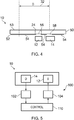
Fig. 4 illustrates another example of optics for an apparatus; and -
Fig. 5 illustrates a photoplethysmography sensor comprising the apparatus. - In order to make a compact and potentially
small scale apparatus 10 it is desirable for alight source 12 at alight detector 14 to be in close proximity. In examples offigures 1 to 3 the light source and the light detector are laterally offset 30 by a distance d. Previously it has been necessary to have this lateral offset distance d greater than 2mm in certain applications such as reflective photoplethysmography. In this constraint it is necessary to ensure that the optical path length from thelight source 12 to thelight detector 14 is of sufficient length. The examples described below provide a new type ofapparatus 10 comprising alight source 12, a light detector andoptics 20. Theoptics 20 enable the lateral offset between thelight source 12 and thelight detector 14 to be less than has previously been possible, that is less than 2mm. -
Fig. 1 illustrates anapparatus 10 comprising: alight detector 14; alight source 12, laterallyoffset 30 from thelight detector 14 by a first lateral offset d;optics 20 configured to receive light emitted by thelight source 12 and output the received light, wherein a majority of the light output is directed towards anoffset region 40 laterallyoffset 32 from thelight detector 14 by at least a second lateral offset D different to the first lateral offset d. - In order to make a compact and potentially
small scale apparatus 10 it is desirable for the second lateral offset D to be greater than the first lateral offset d. -
Figs. 2 and 3 illustrate other examples of theapparatus 10 in whichdifferent optics 20 are used to redirect a majority of thelight 2 received from thelight source 12 towards theoffset region 40 laterallyoffset 32 from thelight detector 14 by at least a second lateral offset D greater than the first lateral offset d. These figures also illustrate that light reflected from theoffset region 40 is detected by thelight detector 14. - In some, but not necessarily all embodiments, the first lateral offset is less than 2mm and the second lateral offset is greater than 2mm. In some embodiments, the second lateral offset is greater than 5mm.
- In some, but not necessarily all examples, the
optics 40 may be configured to defract the receivedlight 2. For example, as illustrated infigs. 2 and 3 , theoptics 20 may have afirst side 21 facing towards thelight source 12 and asecond side 22 facing towards theoffset region 40. Thefirst side 21 comprises a light in-coupling region 23 and thesecond side 22 comprises a light out-coupling region 24. The light in-coupling region is configured to in-couple thelight 2 received from thelight source 12 at a first angle from a normal to the in-coupling region and the light out-coupling region is configured to out-couple thelight 2 at a second angle from a normal 25 to the out-coupling region 24. - In the example illustrated in
fig. 2 , the second angle is greater than the first angle and the in-coupling region 23 and the out-coupling region 24 are in close lateral proximity. - In the example illustrated in
fig. 3 , the light out-coupling region 24 is laterally offset 26 by a lateral offset X from the light in-coupling region 23. The lateral offset X is the difference between the second lateral offset D and the first lateral offset d in this example. Theoptics 20 provides a laterally extendinglight guiding region 28 between the in-coupling region 23 and the out-coupling region 24. This laterallight guiding region 28 is configured to guide thelight 2 by total internal reflection between the in-coupling region 23 and the out-coupling region 24. The total internal reflection traps light inside theoptics 20 between the in-coupling region 23 and the out-coupling region 24 Theoptics 20 therefore extends laterally for at least the offset X and in some examples for a distance as large as the second offset D away from thelight detector 14. As an example, as illustrated infig. 4 theoptics 20 may form awindow 50 overlying both thelight detector 14 and thelight source 12. - The in-
coupling region 23 may be provided by a diffractive structure or by a refractive element or elements. The out-coupling region 24 may be provided by a diffractive structure pattern or by a refractive element or elements. A diffractive structure may for example be a diffractive optical element, a diffraction grating, a periodic structure or pattern or a series of diffraction lines/slits/grooves. - As illustrated in
Fig 4 , thewindow 50 comprises an internal surface 52 (first side 21 of the optics 20) and an external surface 53 (second side 22 of the optics 20). Theinternal surface 52 is an externallyreflective surface 54 such that external light passing through thewindow 50 to thereflective surface 54 is reflected back through thewindow 50 externally. Thereflective surface 54 may in some examples be a specular reflective surface, for example, a mirrored surface. - The
reflective surface 54 comprises anaperture 56 for thelight 2 from thelight source 12 and anaperture 58 for thelight detector 14. Theaperture 58 for thelight detector 14 is generally aligned with the light detector 14 (no lateral offset). Theaperture 56 for thelight 2 from thelight source 12 is generally aligned with the out-coupling region 24 of theoptics 20. In the example ofFig 2 , theaperture 56 would be aligned with thelight source 12 and in the example ofFig 3 , theaperture 56 would be aligned with the out-coupling region 24 is laterallyoffset 26 by a lateral offset X from the light in-coupling region 23. - The
reflective surface 54 extends between the out-coupling region 24 and thelight detector 14 and increases the amount of light from thelight source 12 that ultimately reaches thelight detector 14. - The
reflective surface 54, in the illustrated example, extends over theinternal surface 52 for a distance beyond the second lateral offset D from thelight detector 14. The reflective surface is continuous and uninterrupted except for theapertures reflective surface 54 may extend, in all directions, over theinternal surface 52 for a distance beyond the second lateral offset D from thelight detector 14 and, in this case, theaperture 56 may have an annular shape and surround theaperture 58. - In the above described examples the
light source 12 may be any suitable source oflight 2. For example, it may comprise one or more light emitting diodes. The one or more light emitting diodes may transmit light at the same frequency or at different frequencies. Thelight detector 14 may be any suitable detector of light. For example it may be a photodetector such as a semiconductor photodetector configured, for example, as a photodiode or as a phototransistor. - In the examples of
Figs 3 and4 , the light output by thelight source 12 is directed towards anoffset region 40 laterallyoffset 32 from thelight detector 14 by at least a second lateral offset D different to the first lateral offset d. Theoffset region 40 may for example comprise an annulus of regions that are at the same azimuthal distance from an axis through thelight source 12 orlight detector 14. The annulus may, for example be symmetric about an axis through thelight detector 14 and may have a position displaced along that axis from thelight detector 14. Thelight 2 output by thelight source 12 is directed to the whole of the annulus. -
Fig. 5 illustrates aphotoplethysmography system 100 comprising theapparatus 10. Thesystem 100 comprises drivingcircuitry 104 for driving thelight source 12 of theapparatus 10 anddetection circuitry 102 for receiving an output from thelight detector 14 of theapparatus 10. - In order to obtain a desired signal from the offset region, it may be desirable to use signal processing to separate the desired signal from undesired signal.
- For example, in some but not necessarily all embodiments the offset
region 40 may comprise an arterial blood supply that pulsates. The pulsating blood has a time varying absorption which causes thelight detector 14 to produce a signal with a relatively small time varying component. Extraction of the time varying component associated with the pulse bydetection circuitry 102 provides information specific to the pulsating blood. For example, according to the Beer Lambert law the absorption will depend upon absorptivity of the blood components, concentration of the blood components and a light path length through the arterial blood. - The
apparatus 10 may be configured to compare absorption at different frequencies of light for the same offsetregion 40 at the same time. - The
apparatus 10 may be configured to determine the relative concentrations of analytes in the offsetregion 40 as the light path length through the arterial blood for both light detectors will be the same. This analysis may be performed by theapparatus 10, operating as a pulse oiximeter, using red and infrared light, to determine a concentration of oxyhaemoglobin. - In some but not necessarily all examples,
control circuitry 110 is connected to both the drivingcircuitry 104 and thedetection circuitry 102. Thecontrol circuitry 110 may for example operate thelight source 12 and thelight detector 14 in a coordinated or synchronized manner to reduce noise. For example, the drivingcircuitry 104 may modulate, in time, the amplitude and/or frequency of the light source enabling the separation of a detectedlight 4 arising from thelight source 12 from that arising from ambient light. - In some but not necessarily all examples, the
control circuitry 110 may for example operate thelight source 12 and thelight detector 14 in a time division duplex fashion such that they are not simultaneously operational but that they operate successfully with a time period that is dependent upon the distance of the offsetregion 40 from thelight source 12 and thelight detector 14. It may for example be desirable for thelight detector 14 to be switched off when thelight source 12 is switched on and for thelight detector 14 to be switched on when thelight 2 emitted from thelight source 12 has been reflected by the offsetregion 40 and is at thelight detector 14 It will be appreciated that the timing of the detection can control the location of a target region within the offsetregion 40 from which signals are sampled. - Where a structural feature has been described, it may be replaced by means for performing one or more of the functions of the structural feature whether that function or those functions are explicitly or implicitly described.
- The light source performs the function of providing light and may be replaced by any suitable lighting means. The light detector performs the function of detecting light and may be replaced by any suitable light detection means. The optics performs the function of laterally offsetting the light from the
light source 12 to the offsetregion 40 and may be replaced by any suitable light offsetting means. - The term 'comprise' is used in this document with an inclusive not an exclusive meaning. That is any reference to X comprising Y indicates that X may comprise only one Y or may comprise more than one Y. If it is intended to use 'comprise' with an exclusive meaning then it will be made clear in the context by referring to "comprising only one.." or by using "consisting".
- In this brief description, reference has been made to various examples. The description of features or functions in relation to an example indicates that those features or functions are present in that example. The use of the term 'example' or 'for example' or 'may' in the text denotes, whether explicitly stated or not, that such features or functions are present in at least the described example, whether described as an example or not, and that they can be, but are not necessarily, present in some of or all other examples. Thus 'example', 'for example' or 'may' refers to a particular instance in a class of examples. A property of the instance can be a property of only that instance or a property of the class or a property of a subclass of the class that includes some but not all of the instances in the class. It is therefore implicitly disclosed that a features described with reference to one example but not with reference to another example, can where possible be used in that other example but does not necessarily have to be used in that other example.
- In the foregoing examples, the second lateral offset is greater than the first lateral offset. In other examples, the second lateral offset may be less than the first lateral offset.
- Although embodiments of the present invention have been described in the preceding paragraphs with reference to various examples, it should be appreciated that modifications to the examples given can be made without departing from the scope of the invention as claimed.
- Features described in the preceding description may be used in combinations other than the combinations explicitly described.
- Although functions have been described with reference to certain features, those functions may be performable by other features whether described or not.
- Although features have been described with reference to certain embodiments, those features may also be present in other embodiments whether described or not.
- Whilst endeavoring in the foregoing specification to draw attention to those features of the invention believed to be of particular importance it should be understood that the Applicant claims protection in respect of any patentable feature or combination of features hereinbefore referred to and/or shown in the drawings whether or not particular emphasis has been placed thereon.
Claims (14)
Priority Applications (5)
| Application Number | Priority Date | Filing Date | Title |
|---|---|---|---|
| EP15174687.2A EP3111842B1 (en) | 2015-06-30 | 2015-06-30 | An apparatus comprising a light detector, a light source and optics |
| CN201680038992.4A CN107708558A (en) | 2015-06-30 | 2016-06-02 | Include the equipment of photodetector, light source and optics |
| PCT/FI2016/050395 WO2017001722A1 (en) | 2015-06-30 | 2016-06-02 | An apparatus comprising a light detector, a light source and optics |
| US15/736,237 US11051728B2 (en) | 2015-06-30 | 2016-06-02 | Apparatus comprising a light detector, a light source and optics |
| PH1/2017/502395A PH12017502395B1 (en) | 2015-06-30 | 2016-06-02 | An apparatus comprising a light detector, a light source and optics |
Applications Claiming Priority (1)
| Application Number | Priority Date | Filing Date | Title |
|---|---|---|---|
| EP15174687.2A EP3111842B1 (en) | 2015-06-30 | 2015-06-30 | An apparatus comprising a light detector, a light source and optics |
Publications (2)
| Publication Number | Publication Date |
|---|---|
| EP3111842A1 true EP3111842A1 (en) | 2017-01-04 |
| EP3111842B1 EP3111842B1 (en) | 2025-01-22 |
Family
ID=53491454
Family Applications (1)
| Application Number | Title | Priority Date | Filing Date |
|---|---|---|---|
| EP15174687.2A Active EP3111842B1 (en) | 2015-06-30 | 2015-06-30 | An apparatus comprising a light detector, a light source and optics |
Country Status (5)
| Country | Link |
|---|---|
| US (1) | US11051728B2 (en) |
| EP (1) | EP3111842B1 (en) |
| CN (1) | CN107708558A (en) |
| PH (1) | PH12017502395B1 (en) |
| WO (1) | WO2017001722A1 (en) |
Families Citing this family (1)
| Publication number | Priority date | Publication date | Assignee | Title |
|---|---|---|---|---|
| EP3530175A1 (en) * | 2018-02-26 | 2019-08-28 | Nokia Technologies Oy | Apparatus for optical coherence tomography |
Citations (5)
| Publication number | Priority date | Publication date | Assignee | Title |
|---|---|---|---|---|
| US4880304A (en) * | 1987-04-01 | 1989-11-14 | Nippon Colin Co., Ltd. | Optical sensor for pulse oximeter |
| US20020183623A1 (en) * | 2001-05-31 | 2002-12-05 | Jing Tang | Multi-path optical catheter |
| US20070201788A1 (en) * | 2006-02-27 | 2007-08-30 | Quan Liu | Depth-resolved reflectance instrument and method for its use |
| US20080021330A1 (en) * | 2006-07-21 | 2008-01-24 | Samsung Electronics Co., Ltd. | Apparatus, method and optical sensor module using a tilter for body fat measurement |
| US20120130257A1 (en) * | 2006-05-03 | 2012-05-24 | Joseph Anthony Heanue | Method and apparatus for tissue measurement position tracking and depth adjustment |
Family Cites Families (21)
| Publication number | Priority date | Publication date | Assignee | Title |
|---|---|---|---|---|
| US6725072B2 (en) * | 1990-10-06 | 2004-04-20 | Hema Metrics, Inc. | Sensor for transcutaneous measurement of vascular access blood flow |
| US5638818A (en) * | 1991-03-21 | 1997-06-17 | Masimo Corporation | Low noise optical probe |
| US5995856A (en) * | 1995-11-22 | 1999-11-30 | Nellcor, Incorporated | Non-contact optical monitoring of physiological parameters |
| JP2002501803A (en) | 1998-02-05 | 2002-01-22 | イン−ラインダイアグノスティックスコーポレイション | Non-invasive blood component monitoring method and apparatus |
| US6647279B2 (en) | 2002-03-22 | 2003-11-11 | Jonas Alexander Pologe | Hybrid optical delivery system for photoplethysmography |
| US8131332B2 (en) * | 2002-04-04 | 2012-03-06 | Veralight, Inc. | Determination of a measure of a glycation end-product or disease state using tissue fluorescence of various sites |
| EP1754443A4 (en) * | 2004-06-10 | 2008-10-22 | Matsushita Electric Industrial Co Ltd | LIVING ORGANISM INFORMATION MEASURING INSTRUMENT, STANDARD ELEMENT, AND METHOD FOR USING LIVING ORGANISM INFORMATION MEASURING INSTRUMENT |
| US7598483B2 (en) * | 2005-02-02 | 2009-10-06 | Panasonic Corporation | Optical element and optical measurement device using the optical element |
| US8965472B2 (en) * | 2005-10-21 | 2015-02-24 | Cas Medical Systems, Inc. | Method and apparatus for spectrophotometric based oximetry |
| US8666466B2 (en) | 2009-06-10 | 2014-03-04 | Medtronic, Inc. | Device and method for monitoring of absolute oxygen saturation and tissue hemoglobin concentration |
| US8521244B2 (en) * | 2009-09-16 | 2013-08-27 | Analogic Corporation | Physiological parameter monitoring apparatus |
| JP5672709B2 (en) * | 2010-02-04 | 2015-02-18 | セイコーエプソン株式会社 | Biological information detector, biological information measuring device, and method for designing reflector in biological information detector |
| JP5742104B2 (en) * | 2010-03-25 | 2015-07-01 | セイコーエプソン株式会社 | Optical device and biological information detector |
| US9241635B2 (en) | 2010-09-30 | 2016-01-26 | Fitbit, Inc. | Portable monitoring devices for processing applications and processing analysis of physiological conditions of a user associated with the portable monitoring device |
| US8888701B2 (en) | 2011-01-27 | 2014-11-18 | Valencell, Inc. | Apparatus and methods for monitoring physiological data during environmental interference |
| FR2972622B1 (en) * | 2011-03-18 | 2013-03-29 | Morpho | SENSOR FOR VENOUS NETWORKS OF A PART OF A LIVING BODY |
| US20130289414A1 (en) * | 2012-03-09 | 2013-10-31 | Mahmoudreza Adibnazari | Combined absorption-reflection based instrument and technique to measure antioxidants (including carotenoids) in human tissue |
| US10219709B2 (en) | 2012-03-28 | 2019-03-05 | Wayne State University | Sensor and method for continuous health monitoring |
| US9005129B2 (en) * | 2012-06-22 | 2015-04-14 | Fitbit, Inc. | Wearable heart rate monitor |
| US8954135B2 (en) | 2012-06-22 | 2015-02-10 | Fitbit, Inc. | Portable biometric monitoring devices and methods of operating same |
| CN106333667B (en) * | 2013-06-03 | 2019-07-05 | 飞比特公司 | Wearable heart rate monitor |
-
2015
- 2015-06-30 EP EP15174687.2A patent/EP3111842B1/en active Active
-
2016
- 2016-06-02 US US15/736,237 patent/US11051728B2/en active Active
- 2016-06-02 CN CN201680038992.4A patent/CN107708558A/en active Pending
- 2016-06-02 PH PH1/2017/502395A patent/PH12017502395B1/en unknown
- 2016-06-02 WO PCT/FI2016/050395 patent/WO2017001722A1/en not_active Ceased
Patent Citations (5)
| Publication number | Priority date | Publication date | Assignee | Title |
|---|---|---|---|---|
| US4880304A (en) * | 1987-04-01 | 1989-11-14 | Nippon Colin Co., Ltd. | Optical sensor for pulse oximeter |
| US20020183623A1 (en) * | 2001-05-31 | 2002-12-05 | Jing Tang | Multi-path optical catheter |
| US20070201788A1 (en) * | 2006-02-27 | 2007-08-30 | Quan Liu | Depth-resolved reflectance instrument and method for its use |
| US20120130257A1 (en) * | 2006-05-03 | 2012-05-24 | Joseph Anthony Heanue | Method and apparatus for tissue measurement position tracking and depth adjustment |
| US20080021330A1 (en) * | 2006-07-21 | 2008-01-24 | Samsung Electronics Co., Ltd. | Apparatus, method and optical sensor module using a tilter for body fat measurement |
Also Published As
| Publication number | Publication date |
|---|---|
| WO2017001722A1 (en) | 2017-01-05 |
| PH12017502395A1 (en) | 2018-06-25 |
| CN107708558A (en) | 2018-02-16 |
| US11051728B2 (en) | 2021-07-06 |
| PH12017502395B1 (en) | 2023-02-22 |
| US20180168495A1 (en) | 2018-06-21 |
| EP3111842B1 (en) | 2025-01-22 |
Similar Documents
| Publication | Publication Date | Title |
|---|---|---|
| US20250041509A1 (en) | Infusion system and method which utilizes dual wavelength optical air-in-line detection | |
| CN107019503B (en) | Blood pressure measuring device, and blood pressure measuring device using light source selection process | |
| US20150241347A1 (en) | Nondispersive infrared micro-optics sensor for blood alcohol concentration measurements | |
| CN108009533A (en) | Optical fingerprint identification system | |
| US10548491B2 (en) | Photoplethysmography apparatus | |
| CN107149478A (en) | Determine device and detection means | |
| EP3773176A4 (en) | SENSOR INCLUDING A FIRST OPTICAL ELEMENT HAVING A REFLECTION PROPERTY AND A SECOND OPTICAL ELEMENT HAVING AN ABSORPTION PROPERTY CAPABLE OF ABSORBING THE LIGHT REFLECTED BY THE FIRST OPTICAL ELEMENT AND ELECTRONIC DEVICE INCLUDING THIS | |
| EP2843402A3 (en) | Method and system for detecting a component in a fluid using photo acoustic spectroscopy | |
| CN108981912A (en) | Beam splitting system, optical receiver apparatus, apparatus for measuring biological data and light-splitting method | |
| KR102099935B1 (en) | Time of flight camera apparatus | |
| US11051728B2 (en) | Apparatus comprising a light detector, a light source and optics | |
| JP2006234692A5 (en) | ||
| US9857576B2 (en) | Multi-segment optical component and related optical detecting device capable of increasing SNR | |
| US20250185913A1 (en) | Device and method for analyzing a speckle pattern from biological tissue | |
| WO2018056726A3 (en) | Optical coherence tomography device | |
| RU2009124436A (en) | METHOD AND DEVICE FOR DETECTING AN OBJECT THAT CAN CARRY OUT A REFLECTIVE REFLECTING REFLECTION OF LIGHT | |
| TWI547850B (en) | Optical detecting device capable of increasing signal-to-noise ratio and economizing power consumption | |
| US9980654B2 (en) | Multi-focus physiologic sensing device for condensing light | |
| KR20180098849A (en) | Apparatus for measuring wavelength using light intensity | |
| EP2913658A1 (en) | Optical system and optical quality measuring apparatus | |
| JP2017205383A (en) | Probe for measuring biological information | |
| JP2015011033A (en) | Electromagnetic radiation emission device | |
| JP4400643B2 (en) | Pulse wave sensor | |
| CN209328038U (en) | Imaging system with 3D bio-identification function | |
| JP4889772B2 (en) | Refractometer |
Legal Events
| Date | Code | Title | Description |
|---|---|---|---|
| PUAI | Public reference made under article 153(3) epc to a published international application that has entered the european phase |
Free format text: ORIGINAL CODE: 0009012 |
|
| STAA | Information on the status of an ep patent application or granted ep patent |
Free format text: STATUS: THE APPLICATION HAS BEEN PUBLISHED |
|
| AK | Designated contracting states |
Kind code of ref document: A1 Designated state(s): AL AT BE BG CH CY CZ DE DK EE ES FI FR GB GR HR HU IE IS IT LI LT LU LV MC MK MT NL NO PL PT RO RS SE SI SK SM TR |
|
| AX | Request for extension of the european patent |
Extension state: BA ME |
|
| STAA | Information on the status of an ep patent application or granted ep patent |
Free format text: STATUS: REQUEST FOR EXAMINATION WAS MADE |
|
| 17P | Request for examination filed |
Effective date: 20170704 |
|
| RBV | Designated contracting states (corrected) |
Designated state(s): AL AT BE BG CH CY CZ DE DK EE ES FI FR GB GR HR HU IE IS IT LI LT LU LV MC MK MT NL NO PL PT RO RS SE SI SK SM TR |
|
| RAP1 | Party data changed (applicant data changed or rights of an application transferred) |
Owner name: NOKIA TECHNOLOGIES OY |
|
| STAA | Information on the status of an ep patent application or granted ep patent |
Free format text: STATUS: EXAMINATION IS IN PROGRESS |
|
| 17Q | First examination report despatched |
Effective date: 20200504 |
|
| GRAP | Despatch of communication of intention to grant a patent |
Free format text: ORIGINAL CODE: EPIDOSNIGR1 |
|
| STAA | Information on the status of an ep patent application or granted ep patent |
Free format text: STATUS: GRANT OF PATENT IS INTENDED |
|
| INTG | Intention to grant announced |
Effective date: 20240830 |
|
| GRAS | Grant fee paid |
Free format text: ORIGINAL CODE: EPIDOSNIGR3 |
|
| GRAA | (expected) grant |
Free format text: ORIGINAL CODE: 0009210 |
|
| STAA | Information on the status of an ep patent application or granted ep patent |
Free format text: STATUS: THE PATENT HAS BEEN GRANTED |
|
| AK | Designated contracting states |
Kind code of ref document: B1 Designated state(s): AL AT BE BG CH CY CZ DE DK EE ES FI FR GB GR HR HU IE IS IT LI LT LU LV MC MK MT NL NO PL PT RO RS SE SI SK SM TR |
|
| REG | Reference to a national code |
Ref country code: GB Ref legal event code: FG4D |
|
| REG | Reference to a national code |
Ref country code: CH Ref legal event code: EP |
|
| REG | Reference to a national code |
Ref country code: IE Ref legal event code: FG4D |
|
| REG | Reference to a national code |
Ref country code: DE Ref legal event code: R096 Ref document number: 602015090887 Country of ref document: DE |
|
| REG | Reference to a national code |
Ref country code: NL Ref legal event code: MP Effective date: 20250122 |
|
| PG25 | Lapsed in a contracting state [announced via postgrant information from national office to epo] |
Ref country code: NL Free format text: LAPSE BECAUSE OF FAILURE TO SUBMIT A TRANSLATION OF THE DESCRIPTION OR TO PAY THE FEE WITHIN THE PRESCRIBED TIME-LIMIT Effective date: 20250122 |
|
| PG25 | Lapsed in a contracting state [announced via postgrant information from national office to epo] |
Ref country code: RS Free format text: LAPSE BECAUSE OF FAILURE TO SUBMIT A TRANSLATION OF THE DESCRIPTION OR TO PAY THE FEE WITHIN THE PRESCRIBED TIME-LIMIT Effective date: 20250422 |
|
| PG25 | Lapsed in a contracting state [announced via postgrant information from national office to epo] |
Ref country code: FI Free format text: LAPSE BECAUSE OF FAILURE TO SUBMIT A TRANSLATION OF THE DESCRIPTION OR TO PAY THE FEE WITHIN THE PRESCRIBED TIME-LIMIT Effective date: 20250122 |
|
| PG25 | Lapsed in a contracting state [announced via postgrant information from national office to epo] |
Ref country code: PL Free format text: LAPSE BECAUSE OF FAILURE TO SUBMIT A TRANSLATION OF THE DESCRIPTION OR TO PAY THE FEE WITHIN THE PRESCRIBED TIME-LIMIT Effective date: 20250122 |
|
| PG25 | Lapsed in a contracting state [announced via postgrant information from national office to epo] |
Ref country code: ES Free format text: LAPSE BECAUSE OF FAILURE TO SUBMIT A TRANSLATION OF THE DESCRIPTION OR TO PAY THE FEE WITHIN THE PRESCRIBED TIME-LIMIT Effective date: 20250122 |
|
| PGFP | Annual fee paid to national office [announced via postgrant information from national office to epo] |
Ref country code: GB Payment date: 20250508 Year of fee payment: 11 |
|
| REG | Reference to a national code |
Ref country code: LT Ref legal event code: MG9D |
|
| PG25 | Lapsed in a contracting state [announced via postgrant information from national office to epo] |
Ref country code: IS Free format text: LAPSE BECAUSE OF FAILURE TO SUBMIT A TRANSLATION OF THE DESCRIPTION OR TO PAY THE FEE WITHIN THE PRESCRIBED TIME-LIMIT Effective date: 20250522 Ref country code: NO Free format text: LAPSE BECAUSE OF FAILURE TO SUBMIT A TRANSLATION OF THE DESCRIPTION OR TO PAY THE FEE WITHIN THE PRESCRIBED TIME-LIMIT Effective date: 20250422 |
|
| REG | Reference to a national code |
Ref country code: AT Ref legal event code: MK05 Ref document number: 1760823 Country of ref document: AT Kind code of ref document: T Effective date: 20250122 |
|
| PG25 | Lapsed in a contracting state [announced via postgrant information from national office to epo] |
Ref country code: HR Free format text: LAPSE BECAUSE OF FAILURE TO SUBMIT A TRANSLATION OF THE DESCRIPTION OR TO PAY THE FEE WITHIN THE PRESCRIBED TIME-LIMIT Effective date: 20250122 |
|
| PG25 | Lapsed in a contracting state [announced via postgrant information from national office to epo] |
Ref country code: LV Free format text: LAPSE BECAUSE OF FAILURE TO SUBMIT A TRANSLATION OF THE DESCRIPTION OR TO PAY THE FEE WITHIN THE PRESCRIBED TIME-LIMIT Effective date: 20250122 Ref country code: PT Free format text: LAPSE BECAUSE OF FAILURE TO SUBMIT A TRANSLATION OF THE DESCRIPTION OR TO PAY THE FEE WITHIN THE PRESCRIBED TIME-LIMIT Effective date: 20250522 |
|
| PGFP | Annual fee paid to national office [announced via postgrant information from national office to epo] |
Ref country code: FR Payment date: 20250508 Year of fee payment: 11 |
|
| PG25 | Lapsed in a contracting state [announced via postgrant information from national office to epo] |
Ref country code: GR Free format text: LAPSE BECAUSE OF FAILURE TO SUBMIT A TRANSLATION OF THE DESCRIPTION OR TO PAY THE FEE WITHIN THE PRESCRIBED TIME-LIMIT Effective date: 20250423 Ref country code: BG Free format text: LAPSE BECAUSE OF FAILURE TO SUBMIT A TRANSLATION OF THE DESCRIPTION OR TO PAY THE FEE WITHIN THE PRESCRIBED TIME-LIMIT Effective date: 20250122 |
|
| PG25 | Lapsed in a contracting state [announced via postgrant information from national office to epo] |
Ref country code: AT Free format text: LAPSE BECAUSE OF FAILURE TO SUBMIT A TRANSLATION OF THE DESCRIPTION OR TO PAY THE FEE WITHIN THE PRESCRIBED TIME-LIMIT Effective date: 20250122 |
|
| PG25 | Lapsed in a contracting state [announced via postgrant information from national office to epo] |
Ref country code: SE Free format text: LAPSE BECAUSE OF FAILURE TO SUBMIT A TRANSLATION OF THE DESCRIPTION OR TO PAY THE FEE WITHIN THE PRESCRIBED TIME-LIMIT Effective date: 20250122 |
|
| PG25 | Lapsed in a contracting state [announced via postgrant information from national office to epo] |
Ref country code: SM Free format text: LAPSE BECAUSE OF FAILURE TO SUBMIT A TRANSLATION OF THE DESCRIPTION OR TO PAY THE FEE WITHIN THE PRESCRIBED TIME-LIMIT Effective date: 20250122 |
|
| PG25 | Lapsed in a contracting state [announced via postgrant information from national office to epo] |
Ref country code: DK Free format text: LAPSE BECAUSE OF FAILURE TO SUBMIT A TRANSLATION OF THE DESCRIPTION OR TO PAY THE FEE WITHIN THE PRESCRIBED TIME-LIMIT Effective date: 20250122 |
|
| PG25 | Lapsed in a contracting state [announced via postgrant information from national office to epo] |
Ref country code: IT Free format text: LAPSE BECAUSE OF FAILURE TO SUBMIT A TRANSLATION OF THE DESCRIPTION OR TO PAY THE FEE WITHIN THE PRESCRIBED TIME-LIMIT Effective date: 20250122 |
|
| PG25 | Lapsed in a contracting state [announced via postgrant information from national office to epo] |
Ref country code: EE Free format text: LAPSE BECAUSE OF FAILURE TO SUBMIT A TRANSLATION OF THE DESCRIPTION OR TO PAY THE FEE WITHIN THE PRESCRIBED TIME-LIMIT Effective date: 20250122 Ref country code: CZ Free format text: LAPSE BECAUSE OF FAILURE TO SUBMIT A TRANSLATION OF THE DESCRIPTION OR TO PAY THE FEE WITHIN THE PRESCRIBED TIME-LIMIT Effective date: 20250122 |
|
| REG | Reference to a national code |
Ref country code: DE Ref legal event code: R097 Ref document number: 602015090887 Country of ref document: DE |
|
| PG25 | Lapsed in a contracting state [announced via postgrant information from national office to epo] |
Ref country code: RO Free format text: LAPSE BECAUSE OF FAILURE TO SUBMIT A TRANSLATION OF THE DESCRIPTION OR TO PAY THE FEE WITHIN THE PRESCRIBED TIME-LIMIT Effective date: 20250122 |
|
| PG25 | Lapsed in a contracting state [announced via postgrant information from national office to epo] |
Ref country code: SK Free format text: LAPSE BECAUSE OF FAILURE TO SUBMIT A TRANSLATION OF THE DESCRIPTION OR TO PAY THE FEE WITHIN THE PRESCRIBED TIME-LIMIT Effective date: 20250122 |
|
| PLBE | No opposition filed within time limit |
Free format text: ORIGINAL CODE: 0009261 |
|
| STAA | Information on the status of an ep patent application or granted ep patent |
Free format text: STATUS: NO OPPOSITION FILED WITHIN TIME LIMIT |
|
| REG | Reference to a national code |
Ref country code: CH Ref legal event code: L10 Free format text: ST27 STATUS EVENT CODE: U-0-0-L10-L00 (AS PROVIDED BY THE NATIONAL OFFICE) Effective date: 20251203 |
|
| 26N | No opposition filed |
Effective date: 20251023 |
|
| REG | Reference to a national code |
Ref country code: DE Ref legal event code: R119 Ref document number: 602015090887 Country of ref document: DE |
|
| REG | Reference to a national code |
Ref country code: CH Ref legal event code: H13 Free format text: ST27 STATUS EVENT CODE: U-0-0-H10-H13 (AS PROVIDED BY THE NATIONAL OFFICE) Effective date: 20260127 |
|
| PG25 | Lapsed in a contracting state [announced via postgrant information from national office to epo] |
Ref country code: MC Free format text: LAPSE BECAUSE OF FAILURE TO SUBMIT A TRANSLATION OF THE DESCRIPTION OR TO PAY THE FEE WITHIN THE PRESCRIBED TIME-LIMIT Effective date: 20250122 |
|
| PG25 | Lapsed in a contracting state [announced via postgrant information from national office to epo] |
Ref country code: LU Free format text: LAPSE BECAUSE OF NON-PAYMENT OF DUE FEES Effective date: 20250630 |
|
| REG | Reference to a national code |
Ref country code: BE Ref legal event code: MM Effective date: 20250630 |
|
| PG25 | Lapsed in a contracting state [announced via postgrant information from national office to epo] |
Ref country code: DE Free format text: LAPSE BECAUSE OF NON-PAYMENT OF DUE FEES Effective date: 20260101 Ref country code: IE Free format text: LAPSE BECAUSE OF NON-PAYMENT OF DUE FEES Effective date: 20250630 |
|
| PG25 | Lapsed in a contracting state [announced via postgrant information from national office to epo] |
Ref country code: BE Free format text: LAPSE BECAUSE OF NON-PAYMENT OF DUE FEES Effective date: 20250630 |
|
| PG25 | Lapsed in a contracting state [announced via postgrant information from national office to epo] |
Ref country code: CH Free format text: LAPSE BECAUSE OF NON-PAYMENT OF DUE FEES Effective date: 20250630 |