EP3109985A1 - Eddy current deceleration device equipped with power generation function - Google Patents
Eddy current deceleration device equipped with power generation function Download PDFInfo
- Publication number
- EP3109985A1 EP3109985A1 EP15749358.6A EP15749358A EP3109985A1 EP 3109985 A1 EP3109985 A1 EP 3109985A1 EP 15749358 A EP15749358 A EP 15749358A EP 3109985 A1 EP3109985 A1 EP 3109985A1
- Authority
- EP
- European Patent Office
- Prior art keywords
- braking
- electricity generating
- magnets
- circumferential direction
- permanent magnets
- Prior art date
- Legal status (The legal status is an assumption and is not a legal conclusion. Google has not performed a legal analysis and makes no representation as to the accuracy of the status listed.)
- Granted
Links
Images




Classifications
-
- H—ELECTRICITY
- H02—GENERATION; CONVERSION OR DISTRIBUTION OF ELECTRIC POWER
- H02K—DYNAMO-ELECTRIC MACHINES
- H02K49/00—Dynamo-electric clutches; Dynamo-electric brakes
- H02K49/10—Dynamo-electric clutches; Dynamo-electric brakes of the permanent-magnet type
- H02K49/104—Magnetic couplings consisting of only two coaxial rotary elements, i.e. the driving element and the driven element
- H02K49/106—Magnetic couplings consisting of only two coaxial rotary elements, i.e. the driving element and the driven element with a radial air gap
-
- H—ELECTRICITY
- H02—GENERATION; CONVERSION OR DISTRIBUTION OF ELECTRIC POWER
- H02K—DYNAMO-ELECTRIC MACHINES
- H02K49/00—Dynamo-electric clutches; Dynamo-electric brakes
- H02K49/02—Dynamo-electric clutches; Dynamo-electric brakes of the asynchronous induction type
- H02K49/04—Dynamo-electric clutches; Dynamo-electric brakes of the asynchronous induction type of the eddy-current hysteresis type
-
- B—PERFORMING OPERATIONS; TRANSPORTING
- B60—VEHICLES IN GENERAL
- B60L—PROPULSION OF ELECTRICALLY-PROPELLED VEHICLES; SUPPLYING ELECTRIC POWER FOR AUXILIARY EQUIPMENT OF ELECTRICALLY-PROPELLED VEHICLES; ELECTRODYNAMIC BRAKE SYSTEMS FOR VEHICLES IN GENERAL; MAGNETIC SUSPENSION OR LEVITATION FOR VEHICLES; MONITORING OPERATING VARIABLES OF ELECTRICALLY-PROPELLED VEHICLES; ELECTRIC SAFETY DEVICES FOR ELECTRICALLY-PROPELLED VEHICLES
- B60L1/00—Supplying electric power to auxiliary equipment of vehicles
- B60L1/20—Energy regeneration from auxiliary equipment
-
- B—PERFORMING OPERATIONS; TRANSPORTING
- B60—VEHICLES IN GENERAL
- B60L—PROPULSION OF ELECTRICALLY-PROPELLED VEHICLES; SUPPLYING ELECTRIC POWER FOR AUXILIARY EQUIPMENT OF ELECTRICALLY-PROPELLED VEHICLES; ELECTRODYNAMIC BRAKE SYSTEMS FOR VEHICLES IN GENERAL; MAGNETIC SUSPENSION OR LEVITATION FOR VEHICLES; MONITORING OPERATING VARIABLES OF ELECTRICALLY-PROPELLED VEHICLES; ELECTRIC SAFETY DEVICES FOR ELECTRICALLY-PROPELLED VEHICLES
- B60L7/00—Electrodynamic brake systems for vehicles in general
- B60L7/28—Eddy-current braking
-
- F—MECHANICAL ENGINEERING; LIGHTING; HEATING; WEAPONS; BLASTING
- F16—ENGINEERING ELEMENTS AND UNITS; GENERAL MEASURES FOR PRODUCING AND MAINTAINING EFFECTIVE FUNCTIONING OF MACHINES OR INSTALLATIONS; THERMAL INSULATION IN GENERAL
- F16D—COUPLINGS FOR TRANSMITTING ROTATION; CLUTCHES; BRAKES
- F16D63/00—Brakes not otherwise provided for; Brakes combining more than one of the types of groups F16D49/00 - F16D61/00
- F16D63/002—Brakes with direct electrical or electro-magnetic actuation
-
- H—ELECTRICITY
- H02—GENERATION; CONVERSION OR DISTRIBUTION OF ELECTRIC POWER
- H02K—DYNAMO-ELECTRIC MACHINES
- H02K1/00—Details of the magnetic circuit
- H02K1/06—Details of the magnetic circuit characterised by the shape, form or construction
- H02K1/12—Stationary parts of the magnetic circuit
- H02K1/14—Stator cores with salient poles
-
- H—ELECTRICITY
- H02—GENERATION; CONVERSION OR DISTRIBUTION OF ELECTRIC POWER
- H02K—DYNAMO-ELECTRIC MACHINES
- H02K1/00—Details of the magnetic circuit
- H02K1/06—Details of the magnetic circuit characterised by the shape, form or construction
- H02K1/12—Stationary parts of the magnetic circuit
- H02K1/17—Stator cores with permanent magnets
-
- H—ELECTRICITY
- H02—GENERATION; CONVERSION OR DISTRIBUTION OF ELECTRIC POWER
- H02K—DYNAMO-ELECTRIC MACHINES
- H02K3/00—Details of windings
- H02K3/04—Windings characterised by the conductor shape, form or construction, e.g. with bar conductors
- H02K3/18—Windings for salient poles
-
- H—ELECTRICITY
- H02—GENERATION; CONVERSION OR DISTRIBUTION OF ELECTRIC POWER
- H02K—DYNAMO-ELECTRIC MACHINES
- H02K49/00—Dynamo-electric clutches; Dynamo-electric brakes
- H02K49/02—Dynamo-electric clutches; Dynamo-electric brakes of the asynchronous induction type
- H02K49/04—Dynamo-electric clutches; Dynamo-electric brakes of the asynchronous induction type of the eddy-current hysteresis type
- H02K49/043—Dynamo-electric clutches; Dynamo-electric brakes of the asynchronous induction type of the eddy-current hysteresis type with a radial airgap
-
- H—ELECTRICITY
- H02—GENERATION; CONVERSION OR DISTRIBUTION OF ELECTRIC POWER
- H02K—DYNAMO-ELECTRIC MACHINES
- H02K7/00—Arrangements for handling mechanical energy structurally associated with dynamo-electric machines, e.g. structural association with mechanical driving motors or auxiliary dynamo-electric machines
- H02K7/10—Structural association with clutches, brakes, gears, pulleys or mechanical starters
- H02K7/104—Structural association with clutches, brakes, gears, pulleys or mechanical starters with eddy-current brakes
-
- F—MECHANICAL ENGINEERING; LIGHTING; HEATING; WEAPONS; BLASTING
- F16—ENGINEERING ELEMENTS AND UNITS; GENERAL MEASURES FOR PRODUCING AND MAINTAINING EFFECTIVE FUNCTIONING OF MACHINES OR INSTALLATIONS; THERMAL INSULATION IN GENERAL
- F16D—COUPLINGS FOR TRANSMITTING ROTATION; CLUTCHES; BRAKES
- F16D2121/00—Type of actuator operation force
- F16D2121/18—Electric or magnetic
- F16D2121/20—Electric or magnetic using electromagnets
-
- H—ELECTRICITY
- H02—GENERATION; CONVERSION OR DISTRIBUTION OF ELECTRIC POWER
- H02K—DYNAMO-ELECTRIC MACHINES
- H02K7/00—Arrangements for handling mechanical energy structurally associated with dynamo-electric machines, e.g. structural association with mechanical driving motors or auxiliary dynamo-electric machines
- H02K7/006—Structural association of a motor or generator with the drive train of a motor vehicle
Definitions
- the present invention relates to an eddy current retarder that is to be mounted, as an auxiliary brake, to a vehicle such as a truck and a bus.
- the present invention relates to an eddy current retarder with an electricity generating function that is capable of converting the rotational motion energy of a rotating shaft of a vehicle into braking force, as well as collecting the rotational motion energy as electricity.
- Magnets are indispensable for an eddy current retarder (hereafter, also simply referred to as a retarder) because it generate a magnetic field that provides braking force.
- Retarders are divided roughly into those using permanent magnets and those electromagnets.
- the retarder of any type includes a braking member that is fixed to a rotating shaft such as a propeller shaft. During braking, the action of magnetic fields from magnets generates eddy current on the surface of the braking member facing the magnets. This causes braking force in a direction opposite to a rotational direction on the braking member that rotates together with the rotating shaft, which makes the rotation of the rotating shaft slow down.
- the retarders are categorized into a drum type and a disc type depending on the shape of the braking member and the shape of a magnet retention member that retains the magnets and pairs off with the braking member. There are also various mechanisms for switching between braking and non-braking.
- HEVs hybrid electric vehicles
- EVs electric vehicles
- an electric power generator such as an alternator that receives motive power from an engine to generate electricity.
- an electric power generator such as an alternator
- Patent Literature 1 Japanese Patent Application Publication No. 7-143732
- Patent Literature 2 Japanese Utility Model Laid-Open No. 5-48581
- Patent Literature 3 Japanese Patent Application Publication No. 10-12741
- Patent Literature 4 Japanese Patent Application Publication No. 2001-54276
- This retarder includes a cylindrical braking member that is fixed to a rotating shaft of a vehicle, a cylindrical wound coil retention member that is arranged inside and concentric with this braking member, and a permanent magnet retention member that is arranged inside and concentric with this wound coil retention member.
- the wound coil retention member is of a ferromagnetic material, and is fixed to a non-rotating part of the vehicle.
- the wound coil retention member retains a plurality of excitation coils (including iron cores) on its outer peripheral surface entirely in its circumferential direction, and retains a plurality of electricity generating coils (including iron cores) on its inner peripheral surface entirely in its circumferential direction.
- the permanent magnet retention member is integral with the braking member and retains a plurality of permanent magnets on its outer peripheral surface entirely in its circumferential direction.
- the excitation coils serve as electromagnets by a current supply, and magnetic circuits develop between the electromagnet and the braking member. Then, with relative rotation between the braking member and the wound coil retention member, magnetic fields from the electromagnets fluctuate. This causes eddy current to be generated on the inner peripheral surface of the braking member, providing braking force. Furthermore, magnetic circuits develop between the electricity generating coils and the permanent magnets. Then, with relative rotation between the permanent magnet retention member and the wound coil retention member, magnetic fields from the permanent magnets penetrating the electricity generating coils fluctuate. This causes induced current to flow in the electricity generating coils, providing electricity.
- Patent Literature 5 discloses a drum type, or a disc type, permanent-magnet type retarder with an electricity generating function.
- This retarder includes, in the case of drum type one, a cylindrical braking member that is fixed to a rotating shaft of a vehicle, a magnet retention member that is arranged inside and concentric with this braking member, a brake disc that is integral with this magnet retention member, and a brake caliper that is fixed to a non-rotating part of the vehicle with the brake disc interposed therebetween.
- the magnet retention member is of a ferromagnetic material and rotatably supported by the rotating shaft of the vehicle.
- the magnet retention member retains a plurality of permanent magnets entirely in its circumferential direction such that the permanent magnets face the inner peripheral surface of the braking member.
- a plurality of electricity generating coils are embedded entirely in its circumferential direction.
- the brake caliper is not operated during non-braking.
- the action of magnetic fields from the permanent magnets causes the magnet retention member to rotate in synchronization with the braking member. That is, no relative rotational speed difference arises between the braking member and the permanent magnets, and thus the magnetic fields from the permanent magnets do not fluctuate.
- the magnetic fields penetrating the electricity generating coils do not fluctuate either. This prevents induced current from flowing in the electricity generating coils, generating no electricity.
- the brake caliper is operated during braking. This causes the rotation of the brake disc to stop, thereby making the magnet retention member come to rest. Then, a relative rotational speed difference arises between the braking member and the permanent magnets, and thus the magnetic fields from the permanent magnets fluctuate. This causes eddy current to be generated on the inner peripheral surface of the braking member, generating braking force. Furthermore, the magnetic fields penetrating the electricity generating coils also fluctuate. This causes induced current to flow in the electricity generating coils, generating electricity.
- the magnets for providing braking force namely the permanent magnets are utilized for adding the electricity generating function. Therefore, only providing the electricity generating coils suffices.
- the magnetic fields from the permanent magnets penetrating the electricity generating coils do not fluctuate during non-braking, smooth rotation of the braking member as well as the rotating shaft is not inhibited.
- the electricity generating coils are provided in the braking member rotating with respect to the non-rotating part of the vehicle, which requires a contrivance for the structure of electric contacts with conductors drawn from the electricity generating coils.
- An eddy current retarder with an electricity generating function includes a braking member, a magnet retention member, and a brake switching mechanism, and furthermore has a configuration (1) or (2) described below.
- the braking member is cylindrical and is fixed to a rotating shaft of a vehicle.
- the magnet retention member is a ferromagnetic material arranged inside the braking member, the magnet retention member retains a plurality of magnets at regular intervals entirely in a circumferential direction such that the magnets face the inner peripheral surface of the braking member.
- the brake switching mechanism switches, during braking, to a state in which magnetic circuits develop between the magnets and the braking member, and switches, during non-braking, to a state in which no magnetic circuits develop.
- the retarder of the above (2) preferably has a configuration in which the outer diameter of the end portion of the braking member where the notch portions are provided is smaller than the outer diameter of the portion of the braking member other than the notch portions.
- the magnets are permanent magnets
- the permanent magnets are arranged such that the orientation of the magnetic poles of each permanent magnet is in a radial direction
- the permanent magnets are arranged such that different magnetic poles of adjacent permanent magnets in the circumferential direction alternate.
- This retarder can have the following configuration:
- Generating electricity with an electricity generating coil requires fluctuations of a magnetic field that penetrates the electricity generating coil from a magnet.
- conventional retarders with a generating function utilize a relative rotational speed difference between a magnet and an electricity generating coil. This causes the above problems to become evident.
- the present inventors studied a technique to generate electricity considering not utilizing a relative rotational speed difference between a magnet and an electricity generating coil.
- a drum type retarder as a basis, the present inventors found that it is effective to devise the mounting positions of electricity generating coils, and further to devise the shape of a cylindrical braking member (hereafter, also referred to as a brake drum).
- the following configuration In a drum type retarder, in order to add the electricity generating function while minimizing an increase in the number of components, the following configuration is effective.
- the configuration utilizes magnets (permanent magnets or electromagnets) for providing braking force, including electricity generating coils without including new permanent magnets.
- magnets permanent magnets or electromagnets
- the following configuration is effective.
- the electricity generating coils are fixed to a non-rotating part of a vehicle, and only during braking, magnetic circuits are caused to develop not only between the magnets and the brake drum but also between the magnets and the electricity generating coils.
- Protrusions are provided on an end face of the brake drum in the axial direction of the brake drum, and electricity generating coils are provided so as to face the regions of the end face of the brake drum where these protrusions are provided.
- This configuration causes, when the brake drum rotates during braking, some of the magnetic fields from magnets, which are used originally for generating braking force, to repeatedly penetrate the electricity generating coils through the protrusions on the end face of the brake drum. That is, the magnetic fields penetrating the electricity generating coils fluctuates during braking.
- Notch portions are provided in an end portion of the brake drum in the axial direction of the brake drum, and electricity generating coils are provided so as to face the regions of the end portion of the brake drum where these notch portions are provided (hereafter, also referred to as a notched end portion), from an outer peripheral surface side of the notched end portion.
- This configuration causes, when the brake drum rotates during braking, some of the magnetic fields from magnets, which are used originally for generating braking force, to repeatedly penetrate the electricity generating coils through the notched end portion of the brake drum. That is, the magnetic fields penetrating the electricity generating coils fluctuates during braking.
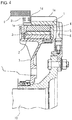
- FIG. 1 is a vertical cross sectional view illustrating a configuration example of an eddy current retarder with an electricity generating function as a first embodiment of the present invention, the vertical cross sectional view being taken along the axial direction of the retarder.
- FIG. 2A to FIG. 2C are cross sectional views of the retarder in the first embodiment, illustrating the main parts of the retarder cut away along a direction perpendicular to the axial direction.
- FIG. 2A and FIG. 2B illustrate the states at different instants in braking, respectively.
- FIG. 2C illustrates the state at an instant in non-braking.
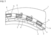
- FIG. 3 is a partially enlarged perspective view of the retarder in the first embodiment.
- protrusions 1c which are provided on an end face 1b of a brake drum 1, are clearly shown by dotted lines. Note that, in FIG. 2A to FIG. 2C , and FIG. 3 , a radiator fin 1a (see FIG. 1 ), which is provided on the outer peripheral surface of the brake drum 1, will not be illustrated.
- the retarder in the first embodiment illustrated in these drawings is a drum type, a permanent-magnet type retarder.
- permanent magnets 3 are used as a magnet to generate braking force, and a turning switch mechanism for switching between braking and non-braking is employed.
- the retarder in the first embodiment includes the brake drum 1 that is cylindrical, a magnet retention ring 2 that is disposed inside this brake drum 1, and a switch plate retention ring 5 that is arranged between the brake drum 1 and the magnet retention ring 2, being concentric with this magnet retention ring 2.
- the brake drum 1 corresponds to a braking member to which braking force is applied.
- the brake drum 1 is fixed to a rotating shaft 10 (e.g., a propeller shaft) of a vehicle via a rotor support member 6 and rotates together with the rotating shaft 10.
- a rotating shaft 10 e.g., a propeller shaft
- the radiator fin 1a is provided on the outer circumference of the brake drum 1. This radiator fin 1a plays a role of cooling the brake drum 1 itself.
- the magnet retention ring 2 corresponds to a magnet retention member that pairs off with the brake drum 1 (the braking member).
- the magnet retention ring 2 is supported by a stator support member 7, so as to turn about the rotating shaft 10.
- the stator support member 7 is fixed to a non-rotating part of the vehicle (e.g., a transmission cover).
- the magnet retention ring 2 is made to turn by the operation of an air cylinder, an electric actuator, or the like, which is not illustrated.
- the outer peripheral surface of the magnet retention ring 2 faces the inner peripheral surface of the brake drum 1, which serves as a braking face.
- a plurality of the permanent magnets 3 are adhered to the outer peripheral surface of the magnet retention ring 2, entirely in its circumferential direction.
- the permanent magnets 3 face the inner peripheral surface of the brake drum 1, and the magnetic poles (the north pole and the south pole) thereof are oriented in the radial direction of the rotating shaft 10. Then, the permanent magnets 3 are arranged at regular intervals such that magnetic poles adjacent to each other in the circumferential direction differ alternately (see FIG. 2A to FIG. 2C ).
- the material of the magnet retention ring 2 is a ferromagnetic material.
- the switch plate retention ring 5 retains, in its circumferential direction, a plurality of switch plates 4 made of a ferromagnetic material, which are necessary for the turning switch mechanism, and is fixed to the stator support member 7. Specifically, the switch plates 4 are provided in the gap between the inner peripheral surface of the brake drum 1 and the permanent magnet 3, entirely in its circumferential direction, such that the arrangement angle of the switch plates 4 matches that of the permanent magnets 3. Each switch plate 4 is substantially the same in size as a single permanent magnet 3.
- a plurality of protrusions 1c are provided on the end face 1b that is open one of both end faces of the brake drum 1 in its axial direction, namely on the end face 1b where the rotor support member 6 for supporting the brake drum 1 is absent. This is for giving rise to the electricity generating function.
- These protrusions 1c are arranged at regular intervals entirely in the circumferential direction. As illustrated in FIG. 2A to FIG. 2C , the arrangement angle of the protrusions 1c matches that of the permanent magnets 3.
- the material quality of the brake drum 1 including the protrusions 1c is ferromagnetic material such as a carbon steel and cast iron. It is more preferable that such a material is used as the base metal of the brake drum 1, and the near-surface portion of the inner peripheral surface is made of a good-conductive material such as a copper and copper alloy. This is because a braking efficiency is thereby enhanced.
- a plurality of electricity generating coils 8 are mounted so as to face the regions of the end face 1b of the brake drum 1 where the protrusions 1c are provided. These electricity generating coils 8 are arranged at regular intervals in a circumferential direction about the rotating shaft 10. The arrangement angle of the electricity generating coils 8 matches that of the permanent magnets 3.
- Each electricity generating coil 8 is a wound coil made by winding a conductor having a high conductivity, such as a copper wire, around an iron core in layers. These electricity generating coils 8 are fixed to a coil support member 9 of a ferromagnetic material and fixed via this coil support member 9 to the non-rotating part of the vehicle (e.g., the transmission cover). The conductors of the electricity generating coils 8 are drawn from the retarder and connected through a control circuit to a storage battery that is installed in the vehicle.
- each switch plate 4 is kept in a state of bridging between permanent magnets 3 adjacent to each other.
- magnetic fluxes (a magnetic field) from the permanent magnets 3 do not reach the brake drum 1. Specifically, the magnetic fluxes from the permanent magnet 3 pass through the switch plate 4, thereafter reach adjacent permanent magnets 3, and return through the magnet retention ring 2. That is, no magnetic circuits develop between the permanent magnets 3 and the brake drum 1.
- the magnet retention ring 2 is turned by half of the arrangement angle of the permanent magnets 3 about the rotating shaft 10. This makes each switch plate 4 kept in a state of being superposed on each permanent magnet 3. In this state, the positions of the permanent magnets 3 coincide with those of the electricity generating coils 8 in the circumferential direction.
- the magnetic fluxes from the permanent magnets 3 penetrate the switch plate 4 facing it to reach the brake drum 1, thereafter penetrate adjacent switch plates 4 to reach permanent magnets 3 facing the adjacent switch plates 4, and return through the magnet retention ring 2. That is, magnetic circuits develop between the permanent magnets 3 and the brake drum 1.
- the brake drum 1 rotates while the permanent magnets 3 and the electricity generating coils 8 are at a standstill with their positions in the circumferential direction coinciding with each other. For this reason, the protrusions 1c provided on the end face 1b of the brake drum 1 are alternately brought into a state where they are positioned facing the electricity generating coils 8 (see FIG. 2A and FIG. 3 ) and a state where they are positioned between electricity generating coils 8 adjacent to each other (see FIG. 2B ).
- the retarder with an electricity generating function in the first embodiment it is possible to generate eddy current on the inner peripheral surface of the brake drum 1 all the time during braking, enabling the stable securement of braking force.
- the induced currents generated in the electricity generating coils 8 can be collected through the conductors that are drawn from the retarder and stored in the storage battery as electricity.
- the electricity collected in the storage battery is used as power sources for a number of electric components mounted in a large vehicle. In the case of a large HEV and a large EV, the electricity collected in the storage battery is used also as a power source for a propulsion electric motor.
- fixing the electricity generating coils 8 to the non-rotating part of the vehicle simplifies a structure for routing the conductors drawn from the electricity generating coils 8.
- smooth rotation of the rotating shaft 10 is not inhibited during non-braking.
- the width of a single protrusion 1c of the brake drum 1 along the circumferential direction is made substantially identical to the width of a single electricity generating coil 8. This is because such a width results in the development of effective fluctuations in magnetic fluxes penetrating the electricity generating coils 8 through the protrusions 1c.
- the projection height of a single protrusion 1c of the brake drum 1 is preferable to make the projection height of a single protrusion 1c of the brake drum 1 about 5 to 10 mm. This is because an excessively small projection height thereof results in ineffective fluctuations in magnetic fluxes penetrating the electricity generating coils 8 through the protrusions 1c, and on the other hand, an excessively large projection height thereof results in ineffective magnetic circuits between the permanent magnets 3 and the electricity generating coils 8 during braking.
- the shape of a single protrusion 1c is not specially limited but is preferably a substantially rectangular-parallelepiped shape made by combining rectangular planes.
- FIG. 4 is a vertical cross sectional view illustrating a configuration example of an eddy current retarder with an electricity generating function as a second embodiment of the present invention, the vertical cross sectional view being taken along the axial direction of the retarder.
- FIG. 5A to FIG. 5C are cross sectional views of the retarder in the second embodiment, illustrating the main parts of the retarder cut away along a direction perpendicular to the axial direction.
- FIG. 5A and FIG. 5B illustrate the states at different instants in braking, respectively.
- FIG. 5C illustrates the state at an instant in non-braking.
- FIG. 6 is a partially enlarged perspective view of the retarder in the second embodiment.
- the retarder in the second embodiment illustrated in these drawings is based on the configuration of the retarder in the first embodiment, but the mounting positions of the electricity generating coils and the shape of the brake drum are different from those in the first embodiment.
- a plurality of notch portions 1e are provided in an end portion 1d that is open one of both end portions of the brake drum 1 in its axial direction, namely in the end portion 1d where the rotor support member 6 for supporting the brake drum 1 is absent. This is for giving rise to the electricity generating function.
- These notch portions 1e are arranged in the end portion 1d at regular intervals entirely in the circumferential direction. As illustrated in FIG. 5A to FIG. 5C , the arrangement angle of the notch portions 1e matches that of the permanent magnets 3.
- the plurality of electricity generating coils 8 are mounted so as to face the regions of the notched end portions 1d of the brake drum 1 from the outer peripheral surface side of the notched end portions 1d. These electricity generating coils 8 are arranged at regular intervals in a circumferential direction about the rotating shaft 10. The arrangement angle of the electricity generating coils 8 matches that of the permanent magnets 3, as illustrated in FIG. 5A to FIG. 5C , and FIG. 6 .
- the outer diameter of the notched end portions 1d of the brake drum 1 is smaller than the outer diameter of the portion of the brake drum 1 other than the end portions 1d. That is, the outer peripheral surfaces of the notched end portions 1d of the brake drum 1 are made a step lower to form recessed spaces, and the above electricity generating coils 8 are housed in the recessed spaces.
- This mode is useful in that it is possible to suppress an increase in size of the retarder as a whole even with the electricity generating coils 8 mounted thereto.
- each switch plate 4 is kept in a state of bridging between the permanent magnets 3 adjacent to each other, as in the first embodiment.
- no magnetic circuits develop between the permanent magnet 3 and the brake drum 1
- no braking force is generated, and no electricity is generated.
- the state of the portion of the brake drum 1 other than the notched end portions 1d is the same as the state illustrated in FIG. 2C described above (except that there are no protrusions 1c).
- the magnetic fluxes from the permanent magnet 3 penetrate the switch plate 4 facing it to reach the brake drum 1, thereafter penetrate adjacent switch plates 4 to reach permanent magnets 3 facing the adjacent switch plates 4, and return through the magnet retention ring 2, as in the first embodiment. That is, magnetic circuits develop between the permanent magnet 3 and the brake drum 1.
- the brake drum 1 rotates while the permanent magnets 3 and the electricity generating coils 8 are at a standstill with their positions in the circumferential direction coinciding with each other. For this reason, the end portions 1d (projecting portions left after forming the notch portions 1e) of the brake drum 1 are alternately brought into a state where they are positioned facing the electricity generating coils 8 (see FIG. 5A ) and a state where they are positioned between electricity generating coils 8 adjacent to each other (see FIG. 5B and FIG. 6 ).
- the retarder with an electricity generating function in the second embodiment also provides the same effect as in the first embodiment.
- the width of a single end portion 1d (a projecting portion left after forming the notch portions 1e) of the brake drum 1 along the circumferential direction is made substantially identical to the width of a single electricity generating coil 8. This is because such a width results in the development of effective fluctuations in magnetic fluxes penetrating the electricity generating coils 8 through the end portions 1d of the brake drum 1.
- the thickness of the notched end portions 1d of the brake drum 1 along their radial directions is about 3 to 10 mm. This is because an excessively small thickness thereof results in ineffective fluctuations in magnetic fluxes penetrating the electricity generating coils 8 through the end portions 1d, and on the other hand, an excessively large thickness thereof results in ineffective magnetic circuits between the permanent magnets 3 and the electricity generating coils 8 during braking.
- the shape of a single notched end portion 1d is not specially limited but is preferably a substantially rectangular-parallelepiped shape made by combining rectangular planes.
- the present invention is not limited to the embodiments described above, and various modifications may be made without departing from the gist and scope of the present invention.
- the above embodiments have the configuration in which the magnet retention ring 2 is turned with respect to the switch plates 4 to switch between braking and non-braking using the turning switch mechanism, but may have a configuration in which the switch plates 4 are turned, as long as the magnet retention ring 2 and the switch plates 4 are relatively turned.
- the above embodiments use permanent magnets as magnets for generating braking force as well as electricity, but these permanent magnets can be substituted with excitation coils (including iron cores) that serve as electromagnets. That is, the present invention is also applicable to a drum-type, electromagnet-type retarder.
- An electromagnet-type retarder dispenses with a turning switch mechanism to switch braking and non-braking.
- the switch plate retention ring 5 is eliminated together with the switch plates 4, and the magnet retention ring 2 is fixed to the stator support member 7. This is because switching between braking and non-braking can be performed by supplying or not supplying current to the excitation coils.
- Example 1 assume the configuration of the retarder in the first embodiment illustrated in FIG. 1 , FIG. 2A to FIG. 2C , and FIG. 3 described above. That is, assume a configuration in which protrusions are provided on an end face of the brake drum, and electricity generating coils are provided facing the regions on the end face. The height of the protrusions was set at about 2 mm.
- electricity generating coils wound coils were prepared, each of which was made by winding 10 turns of a conductor on an iron core, and 32 of the wound coils were mounted and connected in series to one another. The value of electrical resistance of the conductor was set at about 0.37 ⁇ .
- the brake test was conducted using a braking device having such a configuration, and braking forces and induced voltages were measured. These measurements were carried out at the time points when the number of revolutions of the rotating shaft was at 3600 rpm, 2400 rpm, 1800 rpm, 1200 rpm, 600 rpm, and 0 rpm.
- a braking device was used as Comparative Example, the braking device, as illustrated in FIG. 7 , being provided with no protrusions on the end face 1b of the brake drum 1, and no electricity generating coils. Then, the brake test was conducted as with the above, and braking forces were measured.
- braking forces and generated powers were evaluated.
- the evaluation was made using ratios of the braking forces to one as a criterion that is a braking force (620 Nm) measured at the time point when the number of revolutions of the rotating shaft was at 3600 rpm in a brake test using Comparative Example.
- the evaluation was made using ratios of the generated powers to one as a criterion that is an induced voltage (10 V) measured when the number of revolutions of the rotating shaft was at 3600 rpm in a brake test in the inventive example.
- FIG. 8 is a graph illustrating the summary of how the braking force changed, as the test results of Example 1.
- FIG. 9 is a graph illustrating the summary of how the induced voltage changed, as the test results of Example 1.
- the braking force was substantially the same between the retarder in the inventive example (in the first embodiment) and the retarder using the Comparative Example. It can be said, upon this, that the retarder in the first embodiment can secure a braking force as much as a braking device without the electricity generating function.
- the retarder in the inventive example (in the first embodiment) can generate electricity effectively.
- Example 2 assume the configuration of the retarder in the second embodiment illustrated in FIG. 4 , FIG. 5A to FIG. 5C , and FIG. 6 . That is, assume a configuration in which notch portions are provided on an end portion of the brake drum, and electricity generating coils are provided facing the regions of the notched end portions from the outer peripheral surface side of the notched end portions.
- the depth of the notch portions was changed at three levels in ratios of the depths to the overall length of the brake drum in its axial direction as 100% (inventive examples 1 to 3). Specifically, the depth of the notch portions was set at about 15.6% in the inventive example 1, about 21.4% in the inventive example 2, and about 27.2% in the inventive example 3.
- wound coils were prepared, each of which was made by winding 10 turns of a conductor on an iron core having a size corresponding to the depth of the notch portion of each of the inventive examples 1 to 3, and 32 of the wound coils were mounted and connected in series to one another.
- the value of electrical resistance of the conductor was set at about 0.31 Q in the inventive example 1, about 0.38 Q in the inventive example 2, and about 0.44 ⁇ in the inventive example 3.
- the brake test was conducted using braking devices having such configurations, and braking forces and induced voltages were measured. These measurements were carried out at the time points when, as in Example 1, the number of revolutions of the rotating shaft was at 3600 rpm, 2400 rpm, 1800 rpm, 1200 rpm, 600 rpm, and 0 rpm.
- braking forces and generated powers were evaluated.
- the evaluation was made using ratios of the braking forces to one as a criterion that is a braking force (620 Nm) measured at the time point when the number of revolutions of the rotating shaft was at 3600 rpm in a brake test using, as in Example 1 described above, the Comparative Example.
- the generated powers the evaluation was made using ratios of the generated powers to one as a criterion that is an induced voltage (10 V) measured when the number of revolutions of the rotating shaft was at 3600 rpm in a brake test in the inventive example in Example 1 described above.
- FIG. 10 is a graph illustrating the summary of how the braking force changed, as the test results of Example 2.
- the braking forces of the retarders in the inventive examples 1 to 3 were nearly the same as compared with the retarder in the Comparative Example, although there are slight reductions from the retarder in the Comparative Example. It can be said, upon this, that the retarder in the second embodiment can secure a braking force as much as a braking device without the electricity generating function. Note that the reductions in braking force correspond to the depths of the notch portions provided in end portions of the brake drums.
- FIG. 11 is a graph illustrating the summary of how the induced voltage changed, as the test results of Example 2.
- the induced voltages of the retarders in the inventive examples 1 to 3 are small if the notch portions provided in the end portion of the brake drum have a small depth (the inventive example 1), and are large if the notch portions have a large depth (the inventive examples 2 and 3). It can be said that the retarder in the second embodiment can generate electricity more effectively than in the first embodiment depending on the depths of the notch portions.
- the eddy current retarder with an electricity generating function according to the present invention is highly useful as an auxiliary brake for all kinds of vehicles including HEVs and EVs.
Landscapes
- Engineering & Computer Science (AREA)
- Power Engineering (AREA)
- Mechanical Engineering (AREA)
- Transportation (AREA)
- General Engineering & Computer Science (AREA)
- Dynamo-Electric Clutches, Dynamo-Electric Brakes (AREA)
Abstract
Description
- The present invention relates to an eddy current retarder that is to be mounted, as an auxiliary brake, to a vehicle such as a truck and a bus. In particular, the present invention relates to an eddy current retarder with an electricity generating function that is capable of converting the rotational motion energy of a rotating shaft of a vehicle into braking force, as well as collecting the rotational motion energy as electricity.
- Magnets are indispensable for an eddy current retarder (hereafter, also simply referred to as a retarder) because it generate a magnetic field that provides braking force. Retarders are divided roughly into those using permanent magnets and those electromagnets. In general, the retarder of any type includes a braking member that is fixed to a rotating shaft such as a propeller shaft. During braking, the action of magnetic fields from magnets generates eddy current on the surface of the braking member facing the magnets. This causes braking force in a direction opposite to a rotational direction on the braking member that rotates together with the rotating shaft, which makes the rotation of the rotating shaft slow down. The retarders are categorized into a drum type and a disc type depending on the shape of the braking member and the shape of a magnet retention member that retains the magnets and pairs off with the braking member. There are also various mechanisms for switching between braking and non-braking.
- In recent years, along with the prevention of global warming, the improvement in living environment and the reduction in oil dependence have been promoted. For this reason, hybrid electric vehicles (HEVs) and electric vehicles (EVs), which generate motive power for propulsion with an electric motor, have come into widespread use in the areas of not only small vehicles such as cars but also large vehicles such as trucks and buses. In most cases, a large vehicle is equipped with a number of electric components that require electricity. To supply the electricity, a large vehicle is provided with an electric power generator such as an alternator that receives motive power from an engine to generate electricity. However, in large vehicles such as HEVs and EVs, there is a limit to supplying the electricity only by an electric power generator such as an alternator. This is because a propulsion electric motor heavily consumes electricity. For this reason, adding an electricity generating function to a retarder is very useful.
- There are prior art retarders with an electricity generating function, as described below.
- Japanese Patent Application Publication No.
7-143732 5-48581 10-12741 2001-54276 - In the retarders disclosed in
Patent Literatures 1 to 4, the excitation coils serve as electromagnets by a current supply, and magnetic circuits develop between the electromagnet and the braking member. Then, with relative rotation between the braking member and the wound coil retention member, magnetic fields from the electromagnets fluctuate. This causes eddy current to be generated on the inner peripheral surface of the braking member, providing braking force. Furthermore, magnetic circuits develop between the electricity generating coils and the permanent magnets. Then, with relative rotation between the permanent magnet retention member and the wound coil retention member, magnetic fields from the permanent magnets penetrating the electricity generating coils fluctuate. This causes induced current to flow in the electricity generating coils, providing electricity. - Japanese Patent Application Publication No.
2011-182574 - In the retarder disclosed in
Patent Literature 5, the brake caliper is not operated during non-braking. In this state, with the rotation of the braking member, the action of magnetic fields from the permanent magnets causes the magnet retention member to rotate in synchronization with the braking member. That is, no relative rotational speed difference arises between the braking member and the permanent magnets, and thus the magnetic fields from the permanent magnets do not fluctuate. This prevents eddy current from being generated on the inner peripheral surface of the braking member, generating no braking force. Furthermore, the magnetic fields penetrating the electricity generating coils do not fluctuate either. This prevents induced current from flowing in the electricity generating coils, generating no electricity. - On the other hand, the brake caliper is operated during braking. This causes the rotation of the brake disc to stop, thereby making the magnet retention member come to rest. Then, a relative rotational speed difference arises between the braking member and the permanent magnets, and thus the magnetic fields from the permanent magnets fluctuate. This causes eddy current to be generated on the inner peripheral surface of the braking member, generating braking force. Furthermore, the magnetic fields penetrating the electricity generating coils also fluctuate. This causes induced current to flow in the electricity generating coils, generating electricity.
-
- Patent Literature 1:
- Japanese Patent Application Publication No.
7-143732 - Patent Literature 2:
- Japanese Utility Model Laid-Open No.
5-48581 - Patent Literature 3:
- Japanese Patent Application Publication No.
10-12741 - Patent Literature 4:
- Japanese Patent Application Publication No.
2001-54276 - Patent Literature 5:
- Japanese Patent Application Publication No.
2011-182574 - In the retarders disclosed in
Patent Literatures 1 to 4 described above, it is necessary to provide electromagnets, namely excitation coils to provide braking force, which is an essential function. In addition, in order to add the electricity generating function, it is necessary to provide the electricity generating coils as well as the permanent magnets. For this reason, the number of components increases. Moreover, magnetic circuits develop between the electricity generating coils and the permanent magnets all the time. This causes the magnetic fields from the permanent magnets penetrating the electricity generating coils to fluctuate also during non-braking with relative rotation between the permanent magnet retention member and the wound coil retention member. For this reason, under Fleming's left-hand rule, a rotational resistance acts on the permanent magnet retention member. As a result, smooth rotation of the braking member integral with the permanent magnet retention member is inhibited, and thus smooth rotation of the rotating shaft as well. - In contrast, in the retarder disclosed in
Patent Literature 5 described above, the magnets for providing braking force, namely the permanent magnets are utilized for adding the electricity generating function. Therefore, only providing the electricity generating coils suffices. In addition, since the magnetic fields from the permanent magnets penetrating the electricity generating coils do not fluctuate during non-braking, smooth rotation of the braking member as well as the rotating shaft is not inhibited. However, the electricity generating coils are provided in the braking member rotating with respect to the non-rotating part of the vehicle, which requires a contrivance for the structure of electric contacts with conductors drawn from the electricity generating coils. - The present invention is made in the light of the above problems and has an objective to provide an eddy current retarder with an electricity generating function with the following characteristics:
- Adding the electricity generating function while minimizing an increase in the number of components;
- Not inhibiting smooth rotation of the rotating shaft during non-braking; and
- Simplifying a structure for routing the conductors drawn from the electricity generating coils.
- An eddy current retarder with an electricity generating function according to embodiments of the present invention includes a braking member, a magnet retention member, and a brake switching mechanism, and furthermore has a configuration (1) or (2) described below.
- The braking member is cylindrical and is fixed to a rotating shaft of a vehicle.
- The magnet retention member is a ferromagnetic material arranged inside the braking member, the magnet retention member retains a plurality of magnets at regular intervals entirely in a circumferential direction such that the magnets face the inner peripheral surface of the braking member.
- The brake switching mechanism switches, during braking, to a state in which magnetic circuits develop between the magnets and the braking member, and switches, during non-braking, to a state in which no magnetic circuits develop.
-
- (1) The retarder has the following configuration:
- a plurality of protrusions are provided on an end face of the braking member in the axial direction of the braking member at regular intervals entirely in the circumferential direction;
- a plurality of electricity generating coils are provided in a non-rotating part of the vehicle at regular intervals entirely in the circumferential direction such that the electricity generating coils face the regions of the end face of the braking member where the protrusions are provided; and
- during braking, the positions of the magnets coincide with the positions of the electricity generating coils in the circumferential direction.
- (2) The retarder has the following configuration:
- a plurality of notch portions are provided in an end portion of the braking member in the axial direction of the braking member at regular intervals entirely in the circumferential direction;
- a plurality of electricity generating coils are provided in a non-rotating part of the vehicle at regular intervals entirely in the circumferential direction such that the electricity generating coils face the regions of the end portion of the braking member where the notch portions are provided, from the outer peripheral surface side of the braking member;
- during braking, the positions of the magnets coincide with the positions of the electricity generating coils in the circumferential direction.
- The retarder of the above (2) preferably has a configuration in which the outer diameter of the end portion of the braking member where the notch portions are provided is smaller than the outer diameter of the portion of the braking member other than the notch portions.
- In the above-described retarders, it is preferable that the magnets are permanent magnets, the permanent magnets are arranged such that the orientation of the magnetic poles of each permanent magnet is in a radial direction, and the permanent magnets are arranged such that different magnetic poles of adjacent permanent magnets in the circumferential direction alternate.
- This retarder can have the following configuration:
- as the brake switching mechanism, a plurality of switch plates of a ferromagnetic material are provided in a gap between the inner peripheral surface of the braking member and the permanent magnets at regular intervals entirely in the circumferential direction such that an arrangement angle of the switch plates matches an arrangement angle of the permanent magnets; and
- the switch plates is configured to turn relatively to the magnet retention member in the circumferential direction, is kept during braking in a state of being superposed on the permanent magnets, and is kept during non-braking in a state of bridging between the permanent magnets adjacent to each other.
- The eddy current retarder with an electricity generating function according to the present invention has remarkable effects as follows:
- Capable of adding the electricity generating function while minimizing an increase in the number of components;
- Not inhibiting smooth rotation of the rotating shaft during non-braking; and
- Capable of simplifying a structure for routing the conductors drawn from the electricity generating coils.
-
- [
FIG. 1] FIG. 1 is a vertical cross sectional view illustrating a configuration example of an eddy current retarder with an electricity generating function as a first embodiment of the present invention, the vertical cross sectional view being taken along the axial direction of the retarder. - [
FIG. 2A] FIG. 2A is a cross sectional view illustrating a state of the retarder in the first embodiment at an instant in braking. - [
FIG. 2B] FIG. 2B is a cross sectional view illustrating a state of the retarder in the first embodiment at another instant in braking. - [
FIG. 2C] FIG. 2C is a cross sectional view illustrating a state of the retarder in the first embodiment at an instant in non-braking. - [
FIG. 3] FIG. 3 is a partially enlarged perspective view of the retarder in the first embodiment. - [
FIG. 4] FIG. 4 is a vertical cross sectional view illustrating a configuration example of an eddy current retarder with an electricity generating function as a second embodiment of the present invention, the vertical cross sectional view being taken along the axial direction of the retarder. - [
FIG. 5A] FIG. 5A is a cross sectional view illustrating a state of the retarder in the second embodiment at an instant in braking. - [
FIG. 5B] FIG. 5B is a cross sectional view illustrating a state of the retarder in the second embodiment at another instant in braking. - [
FIG. 5C] FIG. 5C is a cross sectional view illustrating a state of the retarder in the second embodiment at an instant in non-braking. - [
FIG. 6] FIG. 6 is a partially enlarged perspective view of the retarder in the second embodiment. - [
FIG. 7] FIG. 7 is a partially enlarged perspective view of a retarder that is used as Comparative Example in a brake test in Example 1. - [
FIG. 8] FIG. 8 is a graph illustrating the summary of how braking force changed, as the test results of Example 1. - [
FIG. 9] FIG. 9 is a graph illustrating the summary of how induced voltage changed, as the test results of Example 1. - [
FIG. 10] FIG. 10 is a graph illustrating the summary of how the braking force changed, as the test results of Example 2. - [
FIG. 11] FIG. 11 is a graph illustrating the summary of how the induced voltage changed, as the test results of Example 2. - Generating electricity with an electricity generating coil requires fluctuations of a magnetic field that penetrates the electricity generating coil from a magnet. In this regard, conventional retarders with a generating function utilize a relative rotational speed difference between a magnet and an electricity generating coil. This causes the above problems to become evident.
- Thus, the present inventors studied a technique to generate electricity considering not utilizing a relative rotational speed difference between a magnet and an electricity generating coil. As a result, with a drum type retarder as a basis, the present inventors found that it is effective to devise the mounting positions of electricity generating coils, and further to devise the shape of a cylindrical braking member (hereafter, also referred to as a brake drum).
- In a drum type retarder, in order to add the electricity generating function while minimizing an increase in the number of components, the following configuration is effective. The configuration utilizes magnets (permanent magnets or electromagnets) for providing braking force, including electricity generating coils without including new permanent magnets. In addition, in order to simplify a structure for routing conductors drawn from the electricity generating coils, as well as not to inhibit smooth rotation of a rotating shaft during non-braking, the following configuration is effective. The electricity generating coils are fixed to a non-rotating part of a vehicle, and only during braking, magnetic circuits are caused to develop not only between the magnets and the brake drum but also between the magnets and the electricity generating coils.
- However, only the magnetic circuits developing between the magnets and the electricity generating coils during braking does not suffice. This is because electricity is not generated unless the magnetic fields penetrating the electricity generating coils fluctuate.
- For this problem, the following configuration is effective. Protrusions are provided on an end face of the brake drum in the axial direction of the brake drum, and electricity generating coils are provided so as to face the regions of the end face of the brake drum where these protrusions are provided. This configuration causes, when the brake drum rotates during braking, some of the magnetic fields from magnets, which are used originally for generating braking force, to repeatedly penetrate the electricity generating coils through the protrusions on the end face of the brake drum. That is, the magnetic fields penetrating the electricity generating coils fluctuates during braking.
- In addition, the following configuration is also effective. Notch portions are provided in an end portion of the brake drum in the axial direction of the brake drum, and electricity generating coils are provided so as to face the regions of the end portion of the brake drum where these notch portions are provided (hereafter, also referred to as a notched end portion), from an outer peripheral surface side of the notched end portion. This configuration causes, when the brake drum rotates during braking, some of the magnetic fields from magnets, which are used originally for generating braking force, to repeatedly penetrate the electricity generating coils through the notched end portion of the brake drum. That is, the magnetic fields penetrating the electricity generating coils fluctuates during braking.
- The present invention is completed based on the above findings. Hereinafter, there will be described preferred embodiments of an eddy current retarder with an electricity generating function according to the present invention.
-
FIG. 1 is a vertical cross sectional view illustrating a configuration example of an eddy current retarder with an electricity generating function as a first embodiment of the present invention, the vertical cross sectional view being taken along the axial direction of the retarder.FIG. 2A to FIG. 2C are cross sectional views of the retarder in the first embodiment, illustrating the main parts of the retarder cut away along a direction perpendicular to the axial direction. Of these drawings,FIG. 2A and FIG. 2B illustrate the states at different instants in braking, respectively.FIG. 2C illustrates the state at an instant in non-braking.FIG. 3 is a partially enlarged perspective view of the retarder in the first embodiment. To facilitate understanding of the device configuration, inFIG. 2A to FIG. 2C ,protrusions 1c, which are provided on anend face 1b of abrake drum 1, are clearly shown by dotted lines. Note that, inFIG. 2A to FIG. 2C , andFIG. 3 , aradiator fin 1a (seeFIG. 1 ), which is provided on the outer peripheral surface of thebrake drum 1, will not be illustrated. - The retarder in the first embodiment illustrated in these drawings is a drum type, a permanent-magnet type retarder. For this retarder,
permanent magnets 3 are used as a magnet to generate braking force, and a turning switch mechanism for switching between braking and non-braking is employed. Specifically, as illustratedFIG. 1 , the retarder in the first embodiment includes thebrake drum 1 that is cylindrical, amagnet retention ring 2 that is disposed inside thisbrake drum 1, and a switchplate retention ring 5 that is arranged between thebrake drum 1 and themagnet retention ring 2, being concentric with thismagnet retention ring 2. - The
brake drum 1 corresponds to a braking member to which braking force is applied. Thebrake drum 1 is fixed to a rotating shaft 10 (e.g., a propeller shaft) of a vehicle via arotor support member 6 and rotates together with the rotatingshaft 10. On the outer circumference of thebrake drum 1, theradiator fin 1a is provided. Thisradiator fin 1a plays a role of cooling thebrake drum 1 itself. - The
magnet retention ring 2 corresponds to a magnet retention member that pairs off with the brake drum 1 (the braking member). Themagnet retention ring 2 is supported by astator support member 7, so as to turn about the rotatingshaft 10. Thestator support member 7 is fixed to a non-rotating part of the vehicle (e.g., a transmission cover). At the time of switching between braking and non-braking, themagnet retention ring 2 is made to turn by the operation of an air cylinder, an electric actuator, or the like, which is not illustrated. - The outer peripheral surface of the
magnet retention ring 2 faces the inner peripheral surface of thebrake drum 1, which serves as a braking face. To the outer peripheral surface of themagnet retention ring 2, entirely in its circumferential direction, a plurality of thepermanent magnets 3 are adhered. Thepermanent magnets 3 face the inner peripheral surface of thebrake drum 1, and the magnetic poles (the north pole and the south pole) thereof are oriented in the radial direction of therotating shaft 10. Then, thepermanent magnets 3 are arranged at regular intervals such that magnetic poles adjacent to each other in the circumferential direction differ alternately (seeFIG. 2A to FIG. 2C ). The material of themagnet retention ring 2 is a ferromagnetic material. - The switch
plate retention ring 5 retains, in its circumferential direction, a plurality ofswitch plates 4 made of a ferromagnetic material, which are necessary for the turning switch mechanism, and is fixed to thestator support member 7. Specifically, theswitch plates 4 are provided in the gap between the inner peripheral surface of thebrake drum 1 and thepermanent magnet 3, entirely in its circumferential direction, such that the arrangement angle of theswitch plates 4 matches that of thepermanent magnets 3. Eachswitch plate 4 is substantially the same in size as a singlepermanent magnet 3. - Here, a plurality of
protrusions 1c are provided on theend face 1b that is open one of both end faces of thebrake drum 1 in its axial direction, namely on theend face 1b where therotor support member 6 for supporting thebrake drum 1 is absent. This is for giving rise to the electricity generating function. Theseprotrusions 1c are arranged at regular intervals entirely in the circumferential direction. As illustrated inFIG. 2A to FIG. 2C , the arrangement angle of theprotrusions 1c matches that of thepermanent magnets 3. - The material quality of the
brake drum 1 including theprotrusions 1c is ferromagnetic material such as a carbon steel and cast iron. It is more preferable that such a material is used as the base metal of thebrake drum 1, and the near-surface portion of the inner peripheral surface is made of a good-conductive material such as a copper and copper alloy. This is because a braking efficiency is thereby enhanced. - Furthermore, a plurality of electricity generating coils 8 are mounted so as to face the regions of the
end face 1b of thebrake drum 1 where theprotrusions 1c are provided. These electricity generating coils 8 are arranged at regular intervals in a circumferential direction about the rotatingshaft 10. The arrangement angle of the electricity generating coils 8 matches that of thepermanent magnets 3. - Each
electricity generating coil 8 is a wound coil made by winding a conductor having a high conductivity, such as a copper wire, around an iron core in layers. These electricity generating coils 8 are fixed to acoil support member 9 of a ferromagnetic material and fixed via thiscoil support member 9 to the non-rotating part of the vehicle (e.g., the transmission cover). The conductors of the electricity generating coils 8 are drawn from the retarder and connected through a control circuit to a storage battery that is installed in the vehicle. - There will be described below the operation of the retarder with an electricity generating function in the first embodiment having such a configuration. During non-braking, as illustrated in
FIG. 2C , eachswitch plate 4 is kept in a state of bridging betweenpermanent magnets 3 adjacent to each other. - In this case, as illustrated by solid arrows in
FIG. 2C , magnetic fluxes (a magnetic field) from thepermanent magnets 3 do not reach thebrake drum 1. Specifically, the magnetic fluxes from thepermanent magnet 3 pass through theswitch plate 4, thereafter reach adjacentpermanent magnets 3, and return through themagnet retention ring 2. That is, no magnetic circuits develop between thepermanent magnets 3 and thebrake drum 1. - In this state during non-braking, since there is no magnetic field reaching the
brake drum 1, no eddy currents are generated on the inner peripheral surface of thebrake drum 1, and thus no braking force is generated. In addition, since there is no magnetic field reaching thebrake drum 1, there is no magnetic field leaking from theprotrusions 1c on theend face 1b of thebrake drum 1 as a natural result. In that case, there is no magnetic field reaching the electricity generating coils 8 either, and thus no induced currents are generated in the electricity generating coils 8, generating no electricity. - On the other hand, during braking, as illustrated in
FIG. 2A and FIG. 2B , themagnet retention ring 2 is turned by half of the arrangement angle of thepermanent magnets 3 about the rotatingshaft 10. This makes eachswitch plate 4 kept in a state of being superposed on eachpermanent magnet 3. In this state, the positions of thepermanent magnets 3 coincide with those of the electricity generating coils 8 in the circumferential direction. - In this case, as illustrated by solid arrows in
FIG. 2A and FIG. 2B , the magnetic fluxes from thepermanent magnets 3 penetrate theswitch plate 4 facing it to reach thebrake drum 1, thereafter penetrateadjacent switch plates 4 to reachpermanent magnets 3 facing theadjacent switch plates 4, and return through themagnet retention ring 2. That is, magnetic circuits develop between thepermanent magnets 3 and thebrake drum 1. - In this state during braking, the magnetic circuits develop between the
permanent magnets 3 and thebrake drum 1, with a relative rotational speed difference occurring between them. For this reason, the magnetic fields on the inner peripheral surface of thebrake drum 1 fluctuate. These fluctuations in magnetic fields cause eddy currents on the inner peripheral surface of thebrake drum 1. The interaction between these eddy currents and the density of the magnetic fluxes from thepermanent magnets 3 causes, under Fleming's left-hand rule, braking force in a direction opposite to the rotational direction on thebrake drum 1 that rotates together with the rotating shaft 10 (see solid black arrows inFIG. 2A and FIG. 2B ). - Here, during braking, the
brake drum 1 rotates while thepermanent magnets 3 and the electricity generating coils 8 are at a standstill with their positions in the circumferential direction coinciding with each other. For this reason, theprotrusions 1c provided on theend face 1b of thebrake drum 1 are alternately brought into a state where they are positioned facing the electricity generating coils 8 (seeFIG. 2A andFIG. 3 ) and a state where they are positioned between electricity generating coils 8 adjacent to each other (seeFIG. 2B ). - When the
protrusions 1c are positioned facing the electricity generating coils 8, some of the magnetic fluxes reaching thebrake drum 1 from apermanent magnet 3 converge into aprotrusion 1c, and leak from there toward theelectricity generating coil 8 to reach the electricity generating coil 8 (see a solid white arrow inFIG. 3 ). These magnetic fluxes having reached theelectricity generating coil 8 penetrate theelectricity generating coil 8 to reach thecoil support member 9, thereafter penetrate adjacent electricity generating coils 8, and pass throughprotrusions 1c facing the adjacent electricity generating coils 8, returning the brake drum 1 (see a hatched arrow inFIG. 3 ). That is, magnetic circuits also develop between thepermanent magnets 3 and the electricity generating coils 8 through thebrake drum 1. - In contrast, as illustrated in
FIG. 2B , when theprotrusions 1c are positioned between electricity generating coils 8 adjacent to each other, theprotrusions 1c does not face the electricity generating coils 8. For this reason, the magnetic fluxes from thepermanent magnets 3 reaching thebrake drum 1 do not leak from theprotrusions 1c, or even otherwise leaking magnetic fluxes are few. That is, the magnetic circuits between thepermanent magnets 3 and the electricity generating coils 8 are interrupted. - As seen from the above, during braking, magnetic fluxes repeatedly penetrate the electricity generating coils 8 through the
protrusions 1c on theend face 1b of thebrake drum 1, and the magnetic fields penetrating the electricity generating coils 8 fluctuate. This causes induced currents by electromagnetic induction to flow through the electricity generating coils 8, generating electricity. - As seen from the above, according to the retarder with an electricity generating function in the first embodiment, it is possible to generate eddy current on the inner peripheral surface of the
brake drum 1 all the time during braking, enabling the stable securement of braking force. At the same time, it is possible to generate induced currents in the electricity generating coils 8, enabling the generation of electricity. The induced currents generated in the electricity generating coils 8 can be collected through the conductors that are drawn from the retarder and stored in the storage battery as electricity. The electricity collected in the storage battery is used as power sources for a number of electric components mounted in a large vehicle. In the case of a large HEV and a large EV, the electricity collected in the storage battery is used also as a power source for a propulsion electric motor. - In addition, in the retarder with an electricity generating function in the first embodiment, no new permanent magnets are mounted to add the electricity generating function. That is, what suffices to add the electricity generating function is only utilizing magnets (the permanent magnets 3) for generating braking force, which is an essential function, and mounting the electricity generating coils 8. For this reason, it is possible to minimize an increase in the number of components.
- In addition, fixing the electricity generating coils 8 to the non-rotating part of the vehicle simplifies a structure for routing the conductors drawn from the electricity generating coils 8. In addition, since the development of the magnetic circuits between the
permanent magnets 3 and thebrake drum 1, and the development of the magnetic circuits between thepermanent magnets 3 and the electricity generating coils 8 are limited during braking, smooth rotation of therotating shaft 10 is not inhibited during non-braking. - The smaller the gap between the electricity generating coils 8 and the
protrusions 1c of thebrake drum 1, the better, but a practical size of the gap is about 1 to 2 mm. This is because an excessively small gap therebetween may cause accidental contact between the electricity generating coils 8 and theprotrusions 1c, leading to breakage, and on the other hand, an excessively large gap results in ineffective magnetic circuits between thepermanent magnets 3 and the electricity generating coils 8 during braking. - In addition, it is preferable that the width of a
single protrusion 1c of thebrake drum 1 along the circumferential direction is made substantially identical to the width of a singleelectricity generating coil 8. This is because such a width results in the development of effective fluctuations in magnetic fluxes penetrating the electricity generating coils 8 through theprotrusions 1c. - Furthermore, it is preferable to make the projection height of a
single protrusion 1c of thebrake drum 1 about 5 to 10 mm. This is because an excessively small projection height thereof results in ineffective fluctuations in magnetic fluxes penetrating the electricity generating coils 8 through theprotrusions 1c, and on the other hand, an excessively large projection height thereof results in ineffective magnetic circuits between thepermanent magnets 3 and the electricity generating coils 8 during braking. - The shape of a
single protrusion 1c is not specially limited but is preferably a substantially rectangular-parallelepiped shape made by combining rectangular planes. -
FIG. 4 is a vertical cross sectional view illustrating a configuration example of an eddy current retarder with an electricity generating function as a second embodiment of the present invention, the vertical cross sectional view being taken along the axial direction of the retarder.FIG. 5A to FIG. 5C are cross sectional views of the retarder in the second embodiment, illustrating the main parts of the retarder cut away along a direction perpendicular to the axial direction. Of these drawings,FIG. 5A and FIG. 5B illustrate the states at different instants in braking, respectively.FIG. 5C illustrates the state at an instant in non-braking.FIG. 6 is a partially enlarged perspective view of the retarder in the second embodiment. The retarder in the second embodiment illustrated in these drawings is based on the configuration of the retarder in the first embodiment, but the mounting positions of the electricity generating coils and the shape of the brake drum are different from those in the first embodiment. - Specifically, a plurality of
notch portions 1e are provided in anend portion 1d that is open one of both end portions of thebrake drum 1 in its axial direction, namely in theend portion 1d where therotor support member 6 for supporting thebrake drum 1 is absent. This is for giving rise to the electricity generating function. Thesenotch portions 1e are arranged in theend portion 1d at regular intervals entirely in the circumferential direction. As illustrated inFIG. 5A to FIG. 5C , the arrangement angle of thenotch portions 1e matches that of thepermanent magnets 3. - Furthermore, the plurality of electricity generating coils 8 are mounted so as to face the regions of the notched
end portions 1d of thebrake drum 1 from the outer peripheral surface side of the notchedend portions 1d. These electricity generating coils 8 are arranged at regular intervals in a circumferential direction about the rotatingshaft 10. The arrangement angle of the electricity generating coils 8 matches that of thepermanent magnets 3, as illustrated inFIG. 5A to FIG. 5C , andFIG. 6 . - Note that, in the retarder in the second embodiment, the outer diameter of the notched
end portions 1d of thebrake drum 1 is smaller than the outer diameter of the portion of thebrake drum 1 other than theend portions 1d. That is, the outer peripheral surfaces of the notchedend portions 1d of thebrake drum 1 are made a step lower to form recessed spaces, and the above electricity generating coils 8 are housed in the recessed spaces. This mode is useful in that it is possible to suppress an increase in size of the retarder as a whole even with the electricity generating coils 8 mounted thereto. - There will be described below the operation of the retarder with an electricity generating function in the second embodiment having such a configuration. During non-braking, as illustrated in
FIG. 5C , eachswitch plate 4 is kept in a state of bridging between thepermanent magnets 3 adjacent to each other, as in the first embodiment. In this case, since no magnetic circuits develop between thepermanent magnet 3 and thebrake drum 1, no braking force is generated, and no electricity is generated. At this point, the state of the portion of thebrake drum 1 other than the notchedend portions 1d is the same as the state illustrated inFIG. 2C described above (except that there are noprotrusions 1c). - On the other hand, during braking, as illustrated in
FIG. 5A and FIG. 5B , themagnet retention ring 2 is turned, as in the first embodiment. This makes eachswitch plate 4 kept in a state of being superposed on eachpermanent magnet 3, and the positions of thepermanent magnets 3 coincide with those of the electricity generating coils 8 in the circumferential direction. At this point, the state of the portion of thebrake drum 1 other than the notchedend portions 1d is the same as the state illustrated inFIG. 2A and FIG. 2B (except that there are noprotrusions 1c). - In this case, in a portion of the
brake drum 1 other than the notchedend portions 1d, as illustrated by the solid arrows inFIG. 2A and FIG. 2B described above, the magnetic fluxes from thepermanent magnet 3 penetrate theswitch plate 4 facing it to reach thebrake drum 1, thereafter penetrateadjacent switch plates 4 to reachpermanent magnets 3 facing theadjacent switch plates 4, and return through themagnet retention ring 2, as in the first embodiment. That is, magnetic circuits develop between thepermanent magnet 3 and thebrake drum 1. - In this state during braking, the magnetic circuits develop between the
permanent magnets 3 and thebrake drum 1, with a relative rotational speed difference occurring between them. For this reason, the magnetic fields on the inner peripheral surface of thebrake drum 1 fluctuate. These fluctuations in magnetic fields cause eddy currents on the inner peripheral surface of thebrake drum 1. The interaction between these eddy currents and the density of the magnetic fluxes from thepermanent magnets 3 causes, under Fleming's left-hand rule, braking force in a direction opposite to the rotational direction on thebrake drum 1 that rotates together with the rotating shaft 10 (see solid black arrows inFIG. 2A and FIG. 2B described above). - Note that in the case of the retarder in the second embodiment, regions where eddy currents are generated are small in the regions of notched
end portion 1d of thebrake drum 1 because thenotch portions 1e are present there. For this reason, the braking force is reduced as compared with the retarder in the first embodiment. - Here, during braking, the
brake drum 1 rotates while thepermanent magnets 3 and the electricity generating coils 8 are at a standstill with their positions in the circumferential direction coinciding with each other. For this reason, theend portions 1d (projecting portions left after forming thenotch portions 1e) of thebrake drum 1 are alternately brought into a state where they are positioned facing the electricity generating coils 8 (seeFIG. 5A ) and a state where they are positioned between electricity generating coils 8 adjacent to each other (seeFIG. 5B andFIG. 6 ). - In the regions of the
end portions 1d of thebrake drum 1, as illustrated inFIG. 5A , when theend portions 1d are positioned facing the electricity generating coils 8, the magnetic fluxes from apermanent magnets 3 having penetrated aswitch plate 4 further penetrate anend portion 1d, reaching anelectricity generating coil 8. These magnetic fluxes having reached theelectricity generating coil 8 penetrate theelectricity generating coil 8 to reach thecoil support member 9, thereafter penetrate adjacent electricity generating coils 8, penetrate theend portions 1d facing the adjacent electricity generating coils 8, and further penetrateswitch plates 4, returning to thepermanent magnets 3 facing theswitch plates 4. That is, magnetic circuits develop also between thepermanent magnets 3 and the electricity generating coils 8. - In contrast, as illustrated in
FIG. 5B , when theend portions 1d are positioned between the electricity generating coils 8 adjacent to each other, namely when thenotch portions 1e are positioned facing the electricity generating coils 8, theend portions 1d do not face the electricity generating coils 8. For this reason, the magnetic circuits between thepermanent magnets 3 and the electricity generating coils 8 are interrupted. - As seen from the above, during braking, magnetic fluxes repeatedly penetrate the electricity generating coils 8 through the notched
end portions 1d of thebrake drum 1, and the magnetic fields penetrating the electricity generating coils 8 fluctuate. This causes induced currents by electromagnetic induction to flow through the electricity generating coils 8, generating electricity. - Consequently, the retarder with an electricity generating function in the second embodiment also provides the same effect as in the first embodiment.
- The smaller the gap between the electricity generating coils 8 and the notched
end portions 1d of thebrake drum 1, the better, but a practical size of the gap is about 1 to 2 mm. This is because an excessively small gap therebetween may cause accidental contact between the electricity generating coils 8 and the notchedend portions 1d, leading to breakage, and on the other hand, an excessively large gap results in ineffective magnetic circuits between thepermanent magnets 3 and the electricity generating coils 8 during braking. - In addition, it is preferable that the width of a
single end portion 1d (a projecting portion left after forming thenotch portions 1e) of thebrake drum 1 along the circumferential direction is made substantially identical to the width of a singleelectricity generating coil 8. This is because such a width results in the development of effective fluctuations in magnetic fluxes penetrating the electricity generating coils 8 through theend portions 1d of thebrake drum 1. - Furthermore, it is preferable to make the thickness of the notched
end portions 1d of thebrake drum 1 along their radial directions about 3 to 10 mm. This is because an excessively small thickness thereof results in ineffective fluctuations in magnetic fluxes penetrating the electricity generating coils 8 through theend portions 1d, and on the other hand, an excessively large thickness thereof results in ineffective magnetic circuits between thepermanent magnets 3 and the electricity generating coils 8 during braking. - The shape of a single notched
end portion 1d is not specially limited but is preferably a substantially rectangular-parallelepiped shape made by combining rectangular planes. - Additionally, the present invention is not limited to the embodiments described above, and various modifications may be made without departing from the gist and scope of the present invention. For example, the above embodiments have the configuration in which the
magnet retention ring 2 is turned with respect to theswitch plates 4 to switch between braking and non-braking using the turning switch mechanism, but may have a configuration in which theswitch plates 4 are turned, as long as themagnet retention ring 2 and theswitch plates 4 are relatively turned. - In addition, the above embodiments use permanent magnets as magnets for generating braking force as well as electricity, but these permanent magnets can be substituted with excitation coils (including iron cores) that serve as electromagnets. That is, the present invention is also applicable to a drum-type, electromagnet-type retarder. An electromagnet-type retarder dispenses with a turning switch mechanism to switch braking and non-braking. In this case, the switch
plate retention ring 5 is eliminated together with theswitch plates 4, and themagnet retention ring 2 is fixed to thestator support member 7. This is because switching between braking and non-braking can be performed by supplying or not supplying current to the excitation coils. - To confirm the effects of the present invention, a brake test was conducted as the following Examples 1 and 2.
- In Example 1, assume the configuration of the retarder in the first embodiment illustrated in
FIG. 1 ,FIG. 2A to FIG. 2C , andFIG. 3 described above. That is, assume a configuration in which protrusions are provided on an end face of the brake drum, and electricity generating coils are provided facing the regions on the end face. The height of the protrusions was set at about 2 mm. As electricity generating coils, wound coils were prepared, each of which was made by winding 10 turns of a conductor on an iron core, and 32 of the wound coils were mounted and connected in series to one another. The value of electrical resistance of the conductor was set at about 0.37 Ω. - As an inventive example, the brake test was conducted using a braking device having such a configuration, and braking forces and induced voltages were measured. These measurements were carried out at the time points when the number of revolutions of the rotating shaft was at 3600 rpm, 2400 rpm, 1800 rpm, 1200 rpm, 600 rpm, and 0 rpm.
- In addition, in order to investigate the influence of adding the electricity generating function on braking force, a braking device was used as Comparative Example, the braking device, as illustrated in
FIG. 7 , being provided with no protrusions on theend face 1b of thebrake drum 1, and no electricity generating coils. Then, the brake test was conducted as with the above, and braking forces were measured. - From these measurement results, braking forces and generated powers were evaluated. As to the braking forces, the evaluation was made using ratios of the braking forces to one as a criterion that is a braking force (620 Nm) measured at the time point when the number of revolutions of the rotating shaft was at 3600 rpm in a brake test using Comparative Example. In addition, as to the generated powers, the evaluation was made using ratios of the generated powers to one as a criterion that is an induced voltage (10 V) measured when the number of revolutions of the rotating shaft was at 3600 rpm in a brake test in the inventive example.
-
FIG. 8 is a graph illustrating the summary of how the braking force changed, as the test results of Example 1.FIG. 9 is a graph illustrating the summary of how the induced voltage changed, as the test results of Example 1. As illustrated inFIG. 8 , it is understood that the braking force was substantially the same between the retarder in the inventive example (in the first embodiment) and the retarder using the Comparative Example. It can be said, upon this, that the retarder in the first embodiment can secure a braking force as much as a braking device without the electricity generating function. In addition, as illustrated inFIG. 9 , it is understood that the retarder in the inventive example (in the first embodiment) can generate electricity effectively. - In Example 2, assume the configuration of the retarder in the second embodiment illustrated in
FIG. 4 ,FIG. 5A to FIG. 5C , andFIG. 6 . That is, assume a configuration in which notch portions are provided on an end portion of the brake drum, and electricity generating coils are provided facing the regions of the notched end portions from the outer peripheral surface side of the notched end portions. - The depth of the notch portions was changed at three levels in ratios of the depths to the overall length of the brake drum in its axial direction as 100% (inventive examples 1 to 3). Specifically, the depth of the notch portions was set at about 15.6% in the inventive example 1, about 21.4% in the inventive example 2, and about 27.2% in the inventive example 3. As electricity generating coils, wound coils were prepared, each of which was made by winding 10 turns of a conductor on an iron core having a size corresponding to the depth of the notch portion of each of the inventive examples 1 to 3, and 32 of the wound coils were mounted and connected in series to one another. The value of electrical resistance of the conductor was set at about 0.31 Q in the inventive example 1, about 0.38 Q in the inventive example 2, and about 0.44 Ω in the inventive example 3.
- The brake test was conducted using braking devices having such configurations, and braking forces and induced voltages were measured. These measurements were carried out at the time points when, as in Example 1, the number of revolutions of the rotating shaft was at 3600 rpm, 2400 rpm, 1800 rpm, 1200 rpm, 600 rpm, and 0 rpm.
- From these measurement results, braking forces and generated powers were evaluated. As to the braking forces, the evaluation was made using ratios of the braking forces to one as a criterion that is a braking force (620 Nm) measured at the time point when the number of revolutions of the rotating shaft was at 3600 rpm in a brake test using, as in Example 1 described above, the Comparative Example. In addition, as to the generated powers, the evaluation was made using ratios of the generated powers to one as a criterion that is an induced voltage (10 V) measured when the number of revolutions of the rotating shaft was at 3600 rpm in a brake test in the inventive example in Example 1 described above.
-
FIG. 10 is a graph illustrating the summary of how the braking force changed, as the test results of Example 2. As illustrated inFIG. 10 , it is understood that the braking forces of the retarders in the inventive examples 1 to 3 (in the second embodiment) were nearly the same as compared with the retarder in the Comparative Example, although there are slight reductions from the retarder in the Comparative Example. It can be said, upon this, that the retarder in the second embodiment can secure a braking force as much as a braking device without the electricity generating function. Note that the reductions in braking force correspond to the depths of the notch portions provided in end portions of the brake drums. -
FIG. 11 is a graph illustrating the summary of how the induced voltage changed, as the test results of Example 2. As illustrated inFIG. 11 , it is understood that, as compared with the retarder in the inventive example in Example 1 described above, the induced voltages of the retarders in the inventive examples 1 to 3 (in the second embodiment) are small if the notch portions provided in the end portion of the brake drum have a small depth (the inventive example 1), and are large if the notch portions have a large depth (the inventive examples 2 and 3). It can be said that the retarder in the second embodiment can generate electricity more effectively than in the first embodiment depending on the depths of the notch portions. - The eddy current retarder with an electricity generating function according to the present invention is highly useful as an auxiliary brake for all kinds of vehicles including HEVs and EVs.
-
- 1:
- Brake drum
- 1a:
- Radiator fin
- 1b:
- End face
- 1c:
- Protrusion
- 1d:
- End portion
- 1e:
- Notch portion
- 2:
- Magnet retention ring
- 3:
- Permanent magnet
- 4:
- Switch plate
- 5:
- Switch plate retention ring
- 6:
- Rotor support member
- 7:
- Stator support member
- 8:
- Electricity generating coil
- 9:
- Coil support member
- 10:
- Rotating shaft
Claims (5)
- An eddy current retarder with an electricity generating function, comprising:a cylindrical braking member that is fixed to a rotating shaft of a vehicle;a magnet retention member of a ferromagnetic material that is arranged inside the braking member, the magnet retention member retaining a plurality of magnets at regular intervals entirely in a circumferential direction such that the magnets face an inner peripheral surface of the braking member; anda brake switching mechanism that switches, during braking, to a state in which magnetic circuits develop between the magnets and the braking member, and switches, during non-braking, to a state in which no magnetic circuits develop, whereina plurality of protrusions are provided on an end face of the braking member in an axial direction at regular intervals entirely in the circumferential direction,a plurality of electricity generating coils are provided in a non-rotating part of the vehicle at regular intervals entirely in the circumferential direction such that the electricity generating coils face regions of the end face of the braking member where the protrusions are provided, andduring braking, positions of the magnets coincide with positions of the electricity generating coils in the circumferential direction.
- An eddy current retarder with an electricity generating function, comprising
a cylindrical braking member that is fixed to a rotating shaft of a vehicle;
a magnet retention member of a ferromagnetic material that is arranged inside the braking member, the magnet retention member retaining a plurality of magnets at regular intervals entirely in a circumferential direction such that the magnets face an inner peripheral surface of the braking member; and
a brake switching mechanism that switches, during braking, to a state in which magnetic circuits develop between the magnets and the braking member, and switches, during non-braking, to a state in which no magnetic circuits develop, wherein
a plurality of notch portions are provided on an end portion of the braking member in an axial direction at regular intervals entirely in the circumferential direction,
a plurality of electricity generating coils are provided in a non-rotating part of the vehicle at regular intervals entirely in the circumferential direction such that the electricity generating coils face regions of the end portion of the braking member where the notch portions are provided, from an outer peripheral surface side of the braking member, and
during braking, positions of the magnets coincide with positions of the electricity generating coils in the circumferential direction. - The eddy current retarder with an electricity generating function according to claim 2, wherein
an outer diameter of the end portion of the braking member where the notch portions are provided is smaller than an outer diameter of a portion of the braking member other than the end portion. - The eddy current retarder with an electricity generating function according to any one of claims 1 to 3, wherein
the magnets are permanent magnets, and
the permanent magnets are arranged such that orientation of the magnetic poles of each permanent magnet is in a radial direction, and the permanent magnets are arranged such that different magnetic poles of adjacent permanent magnets in the circumferential direction alternate. - The eddy current retarder with an electricity generating function according to claim 4, wherein
as the brake switching mechanism, a plurality of switch plates of a ferromagnetic material are provided in a gap between the inner peripheral surface of the braking member and the permanent magnets at regular intervals entirely in the circumferential direction such that an arrangement angle of the switch plates matches an arrangement angle of the permanent magnets, and
the switch plates are configured to turn relatively to the magnet retention member in the circumferential direction, is kept during braking in a state of being superposed on the permanent magnets, and is kept during non-braking in a state of bridging between the permanent magnets adjacent to each other.
Applications Claiming Priority (2)
| Application Number | Priority Date | Filing Date | Title |
|---|---|---|---|
| JP2014027985 | 2014-02-17 | ||
| PCT/JP2015/000508 WO2015122156A1 (en) | 2014-02-17 | 2015-02-05 | Eddy current deceleration device equipped with power generation function |
Publications (3)
| Publication Number | Publication Date |
|---|---|
| EP3109985A1 true EP3109985A1 (en) | 2016-12-28 |
| EP3109985A4 EP3109985A4 (en) | 2017-05-10 |
| EP3109985B1 EP3109985B1 (en) | 2020-01-15 |
Family
ID=53799908
Family Applications (1)
| Application Number | Title | Priority Date | Filing Date |
|---|---|---|---|
| EP15749358.6A Active EP3109985B1 (en) | 2014-02-17 | 2015-02-05 | Eddy current deceleration device equipped with power generation function |
Country Status (6)
| Country | Link |
|---|---|
| US (2) | US10491094B2 (en) |
| EP (1) | EP3109985B1 (en) |
| JP (1) | JP6098738B2 (en) |
| KR (1) | KR101798350B1 (en) |
| CN (1) | CN105993119B (en) |
| WO (1) | WO2015122156A1 (en) |
Families Citing this family (8)
| Publication number | Priority date | Publication date | Assignee | Title |
|---|---|---|---|---|
| KR101798350B1 (en) * | 2014-02-17 | 2017-11-15 | 신닛테츠스미킨 카부시키카이샤 | Eddy current deceleration device equipped with power generation function |
| US20200067397A1 (en) * | 2016-12-21 | 2020-02-27 | Nippon Steel Corporation | Eddy current retarder |
| EP3748824B1 (en) * | 2018-01-29 | 2024-03-06 | Nippon Steel Corporation | Eddy current-type speed-reduction device |
| FR3083386B1 (en) * | 2018-06-28 | 2021-05-14 | Telma | ELECTROMAGNETIC RETARDER AND GENERATOR AND VEHICLE SET CONTAINING SUCH A SET |
| CN111430094B (en) * | 2020-04-23 | 2021-11-23 | 盐城创策知识产权服务有限公司 | High-speed maglev train direction and eddy current braking integrated electromagnet device |
| CN114683864B (en) * | 2020-12-30 | 2023-11-03 | 中国航天科工飞航技术研究院(中国航天海鹰机电技术研究院) | Eddy current brake for vehicle, braking device and method and vehicle |
| TWI867433B (en) * | 2023-02-17 | 2024-12-21 | 張力 | Deceleration brake mechanism |
| KR20240163891A (en) * | 2023-05-11 | 2024-11-19 | 현대자동차주식회사 | Dual rotor motor |
Family Cites Families (24)
| Publication number | Priority date | Publication date | Assignee | Title |
|---|---|---|---|---|
| JPH01298948A (en) * | 1988-05-25 | 1989-12-01 | Sumitomo Metal Ind Ltd | Eddy current type decelerator |
| JPH0683571B2 (en) | 1990-07-30 | 1994-10-19 | いすゞ自動車株式会社 | Eddy current type speed reducer |
| JPH04104314A (en) * | 1990-08-23 | 1992-04-06 | Pfu Ltd | keyboard device |
| JP2661419B2 (en) | 1991-08-09 | 1997-10-08 | 日本電気株式会社 | Parity addition method |
| JPH0583927A (en) * | 1991-09-18 | 1993-04-02 | Isuzu Motors Ltd | Permanent magnet type retarder |
| JPH079085A (en) * | 1993-06-22 | 1995-01-13 | Masamichi Tanaka | Manufacture of partially reformed aluminum-made core for casting |
| JPH07143732A (en) | 1993-11-17 | 1995-06-02 | Sawafuji Electric Co Ltd | Retarder |
| KR100226794B1 (en) | 1996-06-10 | 1999-10-15 | 김영환 | How to make a MOSFET |
| JPH1084664A (en) * | 1996-09-06 | 1998-03-31 | Isuzu Motors Ltd | Permanent magnet type eddy current reducer |
| JPH10127041A (en) | 1996-10-17 | 1998-05-15 | Sawafuji Electric Co Ltd | Excitation core of retarder |
| JPH11187641A (en) * | 1997-12-24 | 1999-07-09 | Isuzu Motors Ltd | Eddy current reducer |
| JPH11285233A (en) * | 1998-03-30 | 1999-10-15 | Isuzu Motors Ltd | Magnet type eddy current reducer |
| JP2001054276A (en) | 1999-08-06 | 2001-02-23 | Sawafuji Electric Co Ltd | Exciter for retarder |
| EP1124311B1 (en) * | 2000-02-10 | 2009-10-21 | Sumitomo Metal Industries, Ltd | Eddy current braking apparatus |
| FR2814003A1 (en) | 2000-09-14 | 2002-03-15 | Labinal | Electrical supply to automobile transmission shaft eddy current brake, in which assembly eliminates the need for liquid cooling system air cooling is sufficient |
| JP2002125361A (en) * | 2000-10-17 | 2002-04-26 | Isuzu Motors Ltd | Eddy current type reduction gear |
| JP4978090B2 (en) * | 2006-07-25 | 2012-07-18 | いすゞ自動車株式会社 | Eddy current reducer |
| FR2904896A1 (en) | 2006-08-10 | 2008-02-15 | Telma Sa | ARRANGEMENT OF AN ELECTRONIC CIRCUIT IN A ROTATING ELECTRICAL MACHINE AND ROTATING ELECTRIC MACHINE COMPRISING SUCH AN ARRANGEMENT |
| CN201234202Y (en) * | 2008-07-23 | 2009-05-06 | 北京齿轮总厂 | Pre-positioning liquid cooling permanent magnet retarder for transmission |
| JP5447003B2 (en) | 2010-03-02 | 2014-03-19 | 新日鐵住金株式会社 | Eddy current reducer with power regeneration function |
| JP5569407B2 (en) | 2011-01-20 | 2014-08-13 | 新日鐵住金株式会社 | Eddy current reducer |
| CN102299608B (en) * | 2011-07-12 | 2013-10-16 | 北京工业大学 | Liquid cooling auto-excitation-type eddy current retarder without electric brush structure |
| KR101798350B1 (en) * | 2014-02-17 | 2017-11-15 | 신닛테츠스미킨 카부시키카이샤 | Eddy current deceleration device equipped with power generation function |
| EP3309944A4 (en) * | 2015-06-12 | 2018-06-13 | Nippon Steel & Sumitomo Metal Corporation | Eddy-current-type deceleration device |
-
2015
- 2015-02-05 KR KR1020167022760A patent/KR101798350B1/en not_active Expired - Fee Related
- 2015-02-05 EP EP15749358.6A patent/EP3109985B1/en active Active
- 2015-02-05 JP JP2015562725A patent/JP6098738B2/en active Active
- 2015-02-05 CN CN201580008485.1A patent/CN105993119B/en not_active Expired - Fee Related
- 2015-02-05 US US15/115,283 patent/US10491094B2/en not_active Expired - Fee Related
- 2015-02-05 WO PCT/JP2015/000508 patent/WO2015122156A1/en not_active Ceased
-
2019
- 2019-09-06 US US16/562,689 patent/US10734881B2/en not_active Expired - Fee Related
Also Published As
| Publication number | Publication date |
|---|---|
| EP3109985A4 (en) | 2017-05-10 |
| WO2015122156A1 (en) | 2015-08-20 |
| US10491094B2 (en) | 2019-11-26 |
| CN105993119B (en) | 2019-06-28 |
| US10734881B2 (en) | 2020-08-04 |
| JP6098738B2 (en) | 2017-03-22 |
| CN105993119A (en) | 2016-10-05 |
| US20190393764A1 (en) | 2019-12-26 |
| US20170005561A1 (en) | 2017-01-05 |
| KR20160111977A (en) | 2016-09-27 |
| JPWO2015122156A1 (en) | 2017-03-30 |
| EP3109985B1 (en) | 2020-01-15 |
| KR101798350B1 (en) | 2017-11-15 |
Similar Documents
| Publication | Publication Date | Title |
|---|---|---|
| US10734881B2 (en) | Eddy current retarder with electricity generating function | |
| US9748806B2 (en) | Permanent magnet rotating electrical machine and a motor vehicle using same | |
| US10122223B2 (en) | Axial gap motor | |
| CN204168022U (en) | Brushless electromagnetism and permanent magnetism mixing excitation generator | |
| JP5752177B2 (en) | Magnet rotating machine | |
| US8648484B2 (en) | Power generating device and braking device | |
| CN110661377B (en) | Assembly with electromagnetic retarder and generator and vehicle comprising such an assembly | |
| JP2007006638A (en) | AC rotating electric machine | |
| CN109478814B (en) | Stator of rotating electric machine and rotating electric machine | |
| JP5427576B2 (en) | Rotating electric machine for vehicles | |
| US20180248453A1 (en) | Rotor, Rotating Electric Machine Including Said Rotor, and Method of Manufacturing Said Rotor | |
| JP6345918B2 (en) | Axial gap motor | |
| JP2015511811A (en) | Power motor generator excited by magnetic transfer | |
| CN110800193A (en) | Stator for rotating electric machine, and method for manufacturing stator for rotating electric machine | |
| JP5569407B2 (en) | Eddy current reducer | |
| JP3774987B2 (en) | AC generator for vehicles | |
| WO2007013207A1 (en) | Superconducting device and axial gap type superconducting motor | |
| CN104659994A (en) | Claw-type hybrid excitation motor | |
| JP3922754B2 (en) | AC generator for vehicles | |
| WO2023195998A1 (en) | Homopolar multi-core energy conversion device | |
| JP2008043093A (en) | Generator | |
| JP6088465B2 (en) | Drive unit | |
| RU2643347C2 (en) | Electrical device for electric energy accumulation by inertial flywheel | |
| JP2004350414A (en) | Rotating electric machine | |
| JP2019537418A (en) | Rotor for rotating electrical machines |
Legal Events
| Date | Code | Title | Description |
|---|---|---|---|
| PUAI | Public reference made under article 153(3) epc to a published international application that has entered the european phase |
Free format text: ORIGINAL CODE: 0009012 |
|
| STAA | Information on the status of an ep patent application or granted ep patent |
Free format text: STATUS: REQUEST FOR EXAMINATION WAS MADE |
|
| 17P | Request for examination filed |
Effective date: 20160901 |
|
| AK | Designated contracting states |
Kind code of ref document: A1 Designated state(s): AL AT BE BG CH CY CZ DE DK EE ES FI FR GB GR HR HU IE IS IT LI LT LU LV MC MK MT NL NO PL PT RO RS SE SI SK SM TR |
|
| AX | Request for extension of the european patent |
Extension state: BA ME |
|
| A4 | Supplementary search report drawn up and despatched |
Effective date: 20170412 |
|
| RIC1 | Information provided on ipc code assigned before grant |
Ipc: H02K 49/10 20060101ALI20170406BHEP Ipc: H02K 7/00 20060101ALI20170406BHEP Ipc: H02K 49/04 20060101ALI20170406BHEP Ipc: H02K 49/02 20060101AFI20170406BHEP |
|
| DAX | Request for extension of the european patent (deleted) | ||
| RAP1 | Party data changed (applicant data changed or rights of an application transferred) |
Owner name: NIPPON STEEL CORPORATION |
|
| GRAP | Despatch of communication of intention to grant a patent |
Free format text: ORIGINAL CODE: EPIDOSNIGR1 |
|
| STAA | Information on the status of an ep patent application or granted ep patent |
Free format text: STATUS: GRANT OF PATENT IS INTENDED |
|
| INTG | Intention to grant announced |
Effective date: 20190710 |
|
| GRAJ | Information related to disapproval of communication of intention to grant by the applicant or resumption of examination proceedings by the epo deleted |
Free format text: ORIGINAL CODE: EPIDOSDIGR1 |
|
| STAA | Information on the status of an ep patent application or granted ep patent |
Free format text: STATUS: REQUEST FOR EXAMINATION WAS MADE |
|
| GRAR | Information related to intention to grant a patent recorded |
Free format text: ORIGINAL CODE: EPIDOSNIGR71 |
|
| GRAS | Grant fee paid |
Free format text: ORIGINAL CODE: EPIDOSNIGR3 |
|
| INTC | Intention to grant announced (deleted) | ||
| STAA | Information on the status of an ep patent application or granted ep patent |
Free format text: STATUS: GRANT OF PATENT IS INTENDED |
|
| GRAA | (expected) grant |
Free format text: ORIGINAL CODE: 0009210 |
|
| STAA | Information on the status of an ep patent application or granted ep patent |
Free format text: STATUS: THE PATENT HAS BEEN GRANTED |
|
| INTG | Intention to grant announced |
Effective date: 20191204 |
|
| AK | Designated contracting states |
Kind code of ref document: B1 Designated state(s): AL AT BE BG CH CY CZ DE DK EE ES FI FR GB GR HR HU IE IS IT LI LT LU LV MC MK MT NL NO PL PT RO RS SE SI SK SM TR |
|
| REG | Reference to a national code |
Ref country code: CH Ref legal event code: EP Ref country code: GB Ref legal event code: FG4D |
|
| REG | Reference to a national code |
Ref country code: IE Ref legal event code: FG4D |
|
| REG | Reference to a national code |
Ref country code: AT Ref legal event code: REF Ref document number: 1226039 Country of ref document: AT Kind code of ref document: T Effective date: 20200215 |
|
| REG | Reference to a national code |
Ref country code: DE Ref legal event code: R096 Ref document number: 602015045626 Country of ref document: DE |
|
| PGFP | Annual fee paid to national office [announced via postgrant information from national office to epo] |
Ref country code: DE Payment date: 20200227 Year of fee payment: 6 |
|
| REG | Reference to a national code |
Ref country code: NL Ref legal event code: MP Effective date: 20200115 |
|
| REG | Reference to a national code |
Ref country code: LT Ref legal event code: MG4D |
|
| PG25 | Lapsed in a contracting state [announced via postgrant information from national office to epo] |
Ref country code: FI Free format text: LAPSE BECAUSE OF FAILURE TO SUBMIT A TRANSLATION OF THE DESCRIPTION OR TO PAY THE FEE WITHIN THE PRESCRIBED TIME-LIMIT Effective date: 20200115 Ref country code: RS Free format text: LAPSE BECAUSE OF FAILURE TO SUBMIT A TRANSLATION OF THE DESCRIPTION OR TO PAY THE FEE WITHIN THE PRESCRIBED TIME-LIMIT Effective date: 20200115 Ref country code: NL Free format text: LAPSE BECAUSE OF FAILURE TO SUBMIT A TRANSLATION OF THE DESCRIPTION OR TO PAY THE FEE WITHIN THE PRESCRIBED TIME-LIMIT Effective date: 20200115 Ref country code: PT Free format text: LAPSE BECAUSE OF FAILURE TO SUBMIT A TRANSLATION OF THE DESCRIPTION OR TO PAY THE FEE WITHIN THE PRESCRIBED TIME-LIMIT Effective date: 20200607 Ref country code: NO Free format text: LAPSE BECAUSE OF FAILURE TO SUBMIT A TRANSLATION OF THE DESCRIPTION OR TO PAY THE FEE WITHIN THE PRESCRIBED TIME-LIMIT Effective date: 20200415 |
|
| PG25 | Lapsed in a contracting state [announced via postgrant information from national office to epo] |
Ref country code: HR Free format text: LAPSE BECAUSE OF FAILURE TO SUBMIT A TRANSLATION OF THE DESCRIPTION OR TO PAY THE FEE WITHIN THE PRESCRIBED TIME-LIMIT Effective date: 20200115 Ref country code: BG Free format text: LAPSE BECAUSE OF FAILURE TO SUBMIT A TRANSLATION OF THE DESCRIPTION OR TO PAY THE FEE WITHIN THE PRESCRIBED TIME-LIMIT Effective date: 20200415 Ref country code: GR Free format text: LAPSE BECAUSE OF FAILURE TO SUBMIT A TRANSLATION OF THE DESCRIPTION OR TO PAY THE FEE WITHIN THE PRESCRIBED TIME-LIMIT Effective date: 20200416 Ref country code: SE Free format text: LAPSE BECAUSE OF FAILURE TO SUBMIT A TRANSLATION OF THE DESCRIPTION OR TO PAY THE FEE WITHIN THE PRESCRIBED TIME-LIMIT Effective date: 20200115 Ref country code: LV Free format text: LAPSE BECAUSE OF FAILURE TO SUBMIT A TRANSLATION OF THE DESCRIPTION OR TO PAY THE FEE WITHIN THE PRESCRIBED TIME-LIMIT Effective date: 20200115 Ref country code: IS Free format text: LAPSE BECAUSE OF FAILURE TO SUBMIT A TRANSLATION OF THE DESCRIPTION OR TO PAY THE FEE WITHIN THE PRESCRIBED TIME-LIMIT Effective date: 20200515 |
|
| REG | Reference to a national code |
Ref country code: CH Ref legal event code: PL |
|
| REG | Reference to a national code |
Ref country code: DE Ref legal event code: R097 Ref document number: 602015045626 Country of ref document: DE |
|
| REG | Reference to a national code |
Ref country code: BE Ref legal event code: MM Effective date: 20200229 |
|
| PG25 | Lapsed in a contracting state [announced via postgrant information from national office to epo] |
Ref country code: CZ Free format text: LAPSE BECAUSE OF FAILURE TO SUBMIT A TRANSLATION OF THE DESCRIPTION OR TO PAY THE FEE WITHIN THE PRESCRIBED TIME-LIMIT Effective date: 20200115 Ref country code: RO Free format text: LAPSE BECAUSE OF FAILURE TO SUBMIT A TRANSLATION OF THE DESCRIPTION OR TO PAY THE FEE WITHIN THE PRESCRIBED TIME-LIMIT Effective date: 20200115 Ref country code: SK Free format text: LAPSE BECAUSE OF FAILURE TO SUBMIT A TRANSLATION OF THE DESCRIPTION OR TO PAY THE FEE WITHIN THE PRESCRIBED TIME-LIMIT Effective date: 20200115 Ref country code: SM Free format text: LAPSE BECAUSE OF FAILURE TO SUBMIT A TRANSLATION OF THE DESCRIPTION OR TO PAY THE FEE WITHIN THE PRESCRIBED TIME-LIMIT Effective date: 20200115 Ref country code: EE Free format text: LAPSE BECAUSE OF FAILURE TO SUBMIT A TRANSLATION OF THE DESCRIPTION OR TO PAY THE FEE WITHIN THE PRESCRIBED TIME-LIMIT Effective date: 20200115 Ref country code: DK Free format text: LAPSE BECAUSE OF FAILURE TO SUBMIT A TRANSLATION OF THE DESCRIPTION OR TO PAY THE FEE WITHIN THE PRESCRIBED TIME-LIMIT Effective date: 20200115 Ref country code: LU Free format text: LAPSE BECAUSE OF NON-PAYMENT OF DUE FEES Effective date: 20200205 Ref country code: MC Free format text: LAPSE BECAUSE OF FAILURE TO SUBMIT A TRANSLATION OF THE DESCRIPTION OR TO PAY THE FEE WITHIN THE PRESCRIBED TIME-LIMIT Effective date: 20200115 Ref country code: ES Free format text: LAPSE BECAUSE OF FAILURE TO SUBMIT A TRANSLATION OF THE DESCRIPTION OR TO PAY THE FEE WITHIN THE PRESCRIBED TIME-LIMIT Effective date: 20200115 Ref country code: LT Free format text: LAPSE BECAUSE OF FAILURE TO SUBMIT A TRANSLATION OF THE DESCRIPTION OR TO PAY THE FEE WITHIN THE PRESCRIBED TIME-LIMIT Effective date: 20200115 |
|
| REG | Reference to a national code |
Ref country code: AT Ref legal event code: MK05 Ref document number: 1226039 Country of ref document: AT Kind code of ref document: T Effective date: 20200115 |
|
| PLBE | No opposition filed within time limit |
Free format text: ORIGINAL CODE: 0009261 |
|
| STAA | Information on the status of an ep patent application or granted ep patent |
Free format text: STATUS: NO OPPOSITION FILED WITHIN TIME LIMIT |
|
| PG25 | Lapsed in a contracting state [announced via postgrant information from national office to epo] |
Ref country code: LI Free format text: LAPSE BECAUSE OF NON-PAYMENT OF DUE FEES Effective date: 20200229 Ref country code: CH Free format text: LAPSE BECAUSE OF NON-PAYMENT OF DUE FEES Effective date: 20200229 |
|
| 26N | No opposition filed |
Effective date: 20201016 |
|
| PG25 | Lapsed in a contracting state [announced via postgrant information from national office to epo] |
Ref country code: AT Free format text: LAPSE BECAUSE OF FAILURE TO SUBMIT A TRANSLATION OF THE DESCRIPTION OR TO PAY THE FEE WITHIN THE PRESCRIBED TIME-LIMIT Effective date: 20200115 Ref country code: IT Free format text: LAPSE BECAUSE OF FAILURE TO SUBMIT A TRANSLATION OF THE DESCRIPTION OR TO PAY THE FEE WITHIN THE PRESCRIBED TIME-LIMIT Effective date: 20200115 Ref country code: FR Free format text: LAPSE BECAUSE OF NON-PAYMENT OF DUE FEES Effective date: 20200315 Ref country code: IE Free format text: LAPSE BECAUSE OF NON-PAYMENT OF DUE FEES Effective date: 20200205 |
|
| PG25 | Lapsed in a contracting state [announced via postgrant information from national office to epo] |
Ref country code: PL Free format text: LAPSE BECAUSE OF FAILURE TO SUBMIT A TRANSLATION OF THE DESCRIPTION OR TO PAY THE FEE WITHIN THE PRESCRIBED TIME-LIMIT Effective date: 20200115 Ref country code: BE Free format text: LAPSE BECAUSE OF NON-PAYMENT OF DUE FEES Effective date: 20200229 Ref country code: SI Free format text: LAPSE BECAUSE OF FAILURE TO SUBMIT A TRANSLATION OF THE DESCRIPTION OR TO PAY THE FEE WITHIN THE PRESCRIBED TIME-LIMIT Effective date: 20200115 |
|
| GBPC | Gb: european patent ceased through non-payment of renewal fee |
Effective date: 20200415 |
|
| PG25 | Lapsed in a contracting state [announced via postgrant information from national office to epo] |
Ref country code: GB Free format text: LAPSE BECAUSE OF NON-PAYMENT OF DUE FEES Effective date: 20200415 |
|
| REG | Reference to a national code |
Ref country code: DE Ref legal event code: R119 Ref document number: 602015045626 Country of ref document: DE |
|
| PG25 | Lapsed in a contracting state [announced via postgrant information from national office to epo] |
Ref country code: DE Free format text: LAPSE BECAUSE OF NON-PAYMENT OF DUE FEES Effective date: 20210901 |
|
| PG25 | Lapsed in a contracting state [announced via postgrant information from national office to epo] |
Ref country code: TR Free format text: LAPSE BECAUSE OF FAILURE TO SUBMIT A TRANSLATION OF THE DESCRIPTION OR TO PAY THE FEE WITHIN THE PRESCRIBED TIME-LIMIT Effective date: 20200115 Ref country code: MT Free format text: LAPSE BECAUSE OF FAILURE TO SUBMIT A TRANSLATION OF THE DESCRIPTION OR TO PAY THE FEE WITHIN THE PRESCRIBED TIME-LIMIT Effective date: 20200115 Ref country code: CY Free format text: LAPSE BECAUSE OF FAILURE TO SUBMIT A TRANSLATION OF THE DESCRIPTION OR TO PAY THE FEE WITHIN THE PRESCRIBED TIME-LIMIT Effective date: 20200115 |
|
| PG25 | Lapsed in a contracting state [announced via postgrant information from national office to epo] |
Ref country code: MK Free format text: LAPSE BECAUSE OF FAILURE TO SUBMIT A TRANSLATION OF THE DESCRIPTION OR TO PAY THE FEE WITHIN THE PRESCRIBED TIME-LIMIT Effective date: 20200115 Ref country code: AL Free format text: LAPSE BECAUSE OF FAILURE TO SUBMIT A TRANSLATION OF THE DESCRIPTION OR TO PAY THE FEE WITHIN THE PRESCRIBED TIME-LIMIT Effective date: 20200115 |