EP3109968A1 - Charging control device - Google Patents
Charging control device Download PDFInfo
- Publication number
- EP3109968A1 EP3109968A1 EP15752855.5A EP15752855A EP3109968A1 EP 3109968 A1 EP3109968 A1 EP 3109968A1 EP 15752855 A EP15752855 A EP 15752855A EP 3109968 A1 EP3109968 A1 EP 3109968A1
- Authority
- EP
- European Patent Office
- Prior art keywords
- charge
- battery
- discharge
- threshold
- calculation unit
- Prior art date
- Legal status (The legal status is an assumption and is not a legal conclusion. Google has not performed a legal analysis and makes no representation as to the accuracy of the status listed.)
- Granted
Links
Images

Classifications
-
- H—ELECTRICITY
- H02—GENERATION; CONVERSION OR DISTRIBUTION OF ELECTRIC POWER
- H02J—ELECTRIC POWER NETWORKS; CIRCUIT ARRANGEMENTS OR SYSTEMS FOR SUPPLYING OR DISTRIBUTING ELECTRIC POWER; SYSTEMS FOR STORING ELECTRIC ENERGY
- H02J7/00—Circuit arrangements for charging or discharging batteries or for supplying loads from batteries
- H02J7/14—Circuit arrangements for charging or discharging batteries or for supplying loads from batteries for charging batteries from dynamo-electric generators driven at varying speed, e.g. on vehicle
-
- H—ELECTRICITY
- H02—GENERATION; CONVERSION OR DISTRIBUTION OF ELECTRIC POWER
- H02J—ELECTRIC POWER NETWORKS; CIRCUIT ARRANGEMENTS OR SYSTEMS FOR SUPPLYING OR DISTRIBUTING ELECTRIC POWER; SYSTEMS FOR STORING ELECTRIC ENERGY
- H02J7/00—Circuit arrangements for charging or discharging batteries or for supplying loads from batteries
- H02J7/80—Circuit arrangements for charging or discharging batteries or for supplying loads from batteries including monitoring or indicating arrangements
- H02J7/82—Control of state of charge [SOC]
-
- H—ELECTRICITY
- H02—GENERATION; CONVERSION OR DISTRIBUTION OF ELECTRIC POWER
- H02J—ELECTRIC POWER NETWORKS; CIRCUIT ARRANGEMENTS OR SYSTEMS FOR SUPPLYING OR DISTRIBUTING ELECTRIC POWER; SYSTEMS FOR STORING ELECTRIC ENERGY
- H02J7/00—Circuit arrangements for charging or discharging batteries or for supplying loads from batteries
- H02J7/90—Regulation of charging or discharging current or voltage
- H02J7/933—Regulation of charging or discharging current or voltage the cycle being controlled or terminated in response to electric parameters
-
- H—ELECTRICITY
- H02—GENERATION; CONVERSION OR DISTRIBUTION OF ELECTRIC POWER
- H02J—ELECTRIC POWER NETWORKS; CIRCUIT ARRANGEMENTS OR SYSTEMS FOR SUPPLYING OR DISTRIBUTING ELECTRIC POWER; SYSTEMS FOR STORING ELECTRIC ENERGY
- H02J7/00—Circuit arrangements for charging or discharging batteries or for supplying loads from batteries
- H02J7/14—Circuit arrangements for charging or discharging batteries or for supplying loads from batteries for charging batteries from dynamo-electric generators driven at varying speed, e.g. on vehicle
- H02J7/1446—Circuit arrangements for charging or discharging batteries or for supplying loads from batteries for charging batteries from dynamo-electric generators driven at varying speed, e.g. on vehicle in response to parameters of a vehicle
-
- H—ELECTRICITY
- H02—GENERATION; CONVERSION OR DISTRIBUTION OF ELECTRIC POWER
- H02J—ELECTRIC POWER NETWORKS; CIRCUIT ARRANGEMENTS OR SYSTEMS FOR SUPPLYING OR DISTRIBUTING ELECTRIC POWER; SYSTEMS FOR STORING ELECTRIC ENERGY
- H02J7/00—Circuit arrangements for charging or discharging batteries or for supplying loads from batteries
- H02J7/60—Circuit arrangements for charging or discharging batteries or for supplying loads from batteries including safety or protection arrangements
- H02J7/63—Circuit arrangements for charging or discharging batteries or for supplying loads from batteries including safety or protection arrangements against overdischarge
-
- Y—GENERAL TAGGING OF NEW TECHNOLOGICAL DEVELOPMENTS; GENERAL TAGGING OF CROSS-SECTIONAL TECHNOLOGIES SPANNING OVER SEVERAL SECTIONS OF THE IPC; TECHNICAL SUBJECTS COVERED BY FORMER USPC CROSS-REFERENCE ART COLLECTIONS [XRACs] AND DIGESTS
- Y02—TECHNOLOGIES OR APPLICATIONS FOR MITIGATION OR ADAPTATION AGAINST CLIMATE CHANGE
- Y02T—CLIMATE CHANGE MITIGATION TECHNOLOGIES RELATED TO TRANSPORTATION
- Y02T10/00—Road transport of goods or passengers
- Y02T10/80—Technologies aiming to reduce greenhouse gasses emissions common to all road transportation technologies
- Y02T10/92—Energy efficient charging or discharging systems for batteries, ultracapacitors, supercapacitors or double-layer capacitors specially adapted for vehicles
Definitions
- the present invention relates to a charging control device, especially relates to a charging control device that is suitable for charging a battery that can be charged and discharged, when the charged state of the battery becomes low.
- Patent Document 1 a device has been known that detects the charged state of a battery that is installed in a vehicle or the like, and can be charged and discharged (see, for example, Patent Document 1).
- the device described in this Patent Document 1 detects a relative charged state by applying time-accumulation to charge and discharge currents detected by a current sensor, or an absolute charged state as the remaining capacity of the battery, based on the charge and discharge currents detected by the current sensor and voltage values. Then, the device executes charge control to charge the battery, by controlling the amount of power generation based on the detected charged states.
- Patent Document 1 Japanese Laid-open Patent Publication No. 2001-157307
- the charge control to charge the battery described above controls the amount of power generation based on the charged states of the battery. Therefore, the charge control can reduce the amount of power generation that consumes fuel (the amount of the power generated by the fuel), which in turn improves the fuel efficiency of the vehicle, and secures a longer battery life.
- the charge control when the absolute charged state of the battery is low, namely, when the remaining capacity of the battery is less than a predetermined threshold, the charge control may be executed to charge the battery. However, if the charge control is executed uniformly just because the remaining capacity of the battery has become less than the predetermined threshold, regardless of the charge and discharge of the battery being balanced relatively or in a short-term, the charge control places a high load on the vehicle engine, and hence, the effect of improving the vehicle fuel efficiency by the charge control may be reduced.
- a charging control device that includes a charged state calculation unit configured to calculate a remaining capacity of a battery that can be charged and discharged, based on a signal from a sensor to detect a state of the battery; an accumulated charge and discharge calculation unit configured to calculate an accumulated amount of charge and discharge of the battery after an activation of the battery, based on the signal from the sensor; an execution determination unit configured, in a case where the remaining capacity calculated by the charged state calculation unit is less than a first threshold, to determine whether to execute charge control to recover the remaining capacity of the battery, based on the accumulated amount calculated by the accumulated charge and discharge calculation unit; and a charge control unit configured to execute the charge control following a determination result by the execution determination unit.
- a charging control device can execute charge control appropriately, without reducing the effect of the charge control.
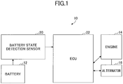
- FIG. 1 is a configuration diagram of a system that includes a charging control device 10 according to an embodiment of the present invention. Also, FIG. 2 is a block configuration diagram of the charging control device 10 according to the embodiment.
- the system in the embodiment is an invehicle system installed in a vehicle.
- the vehicle includes a battery 12, an engine 14, and an alternator 16.
- the battery 12 is a battery that can be charged and discharged, supplies accumulated electric power to external invehicle electric devices, and accumulates electric power supplied by the alternator 16.
- the battery 12 has a predetermined capacity to be capable of accumulating a predetermined amount of electric power.
- the engine 14 generates motive power by receiving fuel supply, which is mainly used for driving the vehicle.
- the alternator 16 is connected with the engine 14 mechanically, and can generate electric power when the engine 14 is put into operation.
- the alternator 16 is connected with the battery 12 via a power cable, and can supply generated power to the battery 12.
- the charging control device 10 includes sensors 20 to detect states of the battery 12.
- the sensors 20 include a battery current sensor, a battery voltage sensor, and a battery temperature sensor.
- the battery current sensor is a sensor to output a signal that corresponds to charge and discharge currents (namely, a battery current(s)) I of the battery 12, specifically, a signal that corresponds to an instantaneous value of a current (a charge current) flowing into the battery 12, and a current (a discharge current) flowing out of the battery 12.
- the battery voltage sensor is a sensor to output a signal that corresponds to a voltage value (battery voltage) V generated between both terminals of the battery 12.
- the battery temperature sensor is a sensor to output a signal that corresponds to the temperature of the battery 12, or an atmospheric temperature T around the battery 12.
- the charging control device 10 also includes an electronic control unit (referred to as an "ECU” below) 22 mainly constituted with a microcomputer.
- the output of the sensors 20 is supplied to the ECU 22.
- the ECU 22 includes a battery current measurement unit 24, a battery voltage measurement unit 26, and a battery temperature measurement unit 28 that respectively detect the charge and discharge current I, the battery voltage V, and the battery temperature T, based on the signals supplied as input from the sensors 20.
- the ECU 22 detects various states of the battery 12, based on the charge and discharge current I, the battery voltage V, and the battery temperature T of the battery 12 detected as described above.
- the ECU 22 includes a charge/discharge current calculation unit 30 and an absolute charged state calculation unit 32.
- the charge/discharge current calculation unit 30 is a part to calculate an amount of accumulation ⁇ I, which is a time-accumulated amount of charge and discharge currents of the battery 12 detected by using the sensors 20 during a trip since the vehicle has been started (namely, the engine 14 has been started).
- the absolute charged state calculation unit 32 is a part to calculate an absolute capacity (namely, the remaining capacity of the battery) C of the battery 12 at a current timing, based on the charge and discharge current I, the battery voltage V, and the battery temperature T of the battery 12 detected by using the sensors 20, with reference to a predetermined map.
- the ECU 22 also includes a determination condition selection unit 34, a charge-discharge balance determination unit 36, and a power control unit 38.
- the determination condition selection unit 34 is a part to select a condition to be used by the charge-discharge balance determination unit 36 when determining whether the charge and discharge of the battery 12 are balanced.
- the charge-discharge balance determination unit 36 is a part to determine whether the charge and discharge of the battery 12 are balanced. Note that the balance between the charge and discharge may include both a relative (short-term) balance and an absolute (long-term) balance.
- the power control unit 38 is a part electrically connected with the engine 14 and the alternator 16, to execute power control of the vehicle by using the engine 14 and the alternator 16; specifically, to execute charge control to charge the battery 12 if the charge-discharge balance determination unit 36 determines that the balance between the charge and discharge of the battery 12 is excessively discharged.
- This charge control is to recover the remaining capacity of the battery 12, by increasing the rotational speed of the engine 14, or raising the power generation voltage of the alternator 16.
- the objectives of the charge control are to improve the vehicle fuel efficiency by reducing the fuel consumption amount consumed by the engine 14, and to secure a longer battery life.
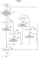
- FIG. 3 is an example of a flowchart of a control routine executed by the ECU 22 of the charging control device in the embodiment. Note that execution of the routine illustrated in FIG. 3 starts when the vehicle is started (namely, the engine 14 is started), and ends when the engine 14 is stopped.
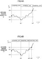
- FIG. 4A is an example of an operational timing chart that is implemented when determining whether the charge and discharge of the battery 12 are balanced is to be executed based on the remaining battery capacity C in the charging control device 10 in the embodiment.
- FIG. 4B is an example of an operational timing chart that is implemented when determining whether the charge and discharge of the battery 12 are balanced is to be executed based on the time-accumulated amount of charge and discharge currents ⁇ I in the charging control device 10 in the embodiment.
- the ECU 22 detects the states of the battery 12 at predetermined times after the vehicle has been started. Specifically, the charge/discharge current calculation unit 30 calculates an amount of accumulation ⁇ I, which is a time-accumulated amount of charge and discharge currents I of the battery 12 detected by using the sensors 20 during a trip after the vehicle has been started, and the absolute charged state calculation unit 32 calculates the remaining battery capacity C of the battery 12.
- ⁇ I is a time-accumulated amount of charge and discharge currents I of the battery 12 detected by using the sensors 20 during a trip after the vehicle has been started
- the absolute charged state calculation unit 32 calculates the remaining battery capacity C of the battery 12.
- the ECU 22 determines whether it is necessary to execute the charge control of the battery 12, based on the states of the battery. Specifically, first, based on the remaining battery capacity C calculated by the absolute charged state calculation unit 32, the determination condition selection unit 34 selects a condition used for determining whether the charge and discharge of the battery 12 are balanced. This condition used for determining whether the charge and discharge of the battery 12 are balanced is selected among (1) a condition based on the remaining battery capacity C calculated by the absolute charged state calculation unit 32, and (2) a condition based on the time-accumulated amount of charge and discharge currents ⁇ I calculated by the charge/discharge current calculation unit 30 during the trip. Then, following the condition selected by the determination condition selection unit 34, the charge-discharge balance determination unit 36 determines whether the charge and discharge of the battery 12 are balanced.
- the determination condition selection unit 34 first determines whether a state has been satisfied even once during the trip in which the remaining battery capacity C calculated by the absolute charged state calculation unit 32 is greater than or equal to a first threshold th1 (Step 100).
- this first threshold th1 is a remaining capacity of the battery to switch between the condition (1) based on the remaining battery capacity C calculated by the absolute charged state calculation unit 32, and the condition (2) based on the time-accumulated amount of charge and discharge currents ⁇ I calculated by the charge/discharge current calculation unit 30 during the trip, for determining whether the charge and discharge of the battery 12 are balanced, which is set in advance to a remaining capacity of the battery, for example, 85% or the like with respect to the fully charged state.
- the determination condition selection unit 34 selects the condition (1) based on the remaining battery capacity C calculated by the absolute charged state calculation unit 32, for determining whether the charge and discharge are balanced. On the other hand, if determining that a state has never been satisfied during the trip in which the remaining battery capacity C calculated by the absolute charged state calculation unit 32 is greater than or equal to the first threshold th1 (negative determination at Step 100), the determination condition selection unit 34 selects the condition (2) based on the time-accumulated amount of charge and discharge currents ⁇ I calculated by the charge/discharge current calculation unit 30 during the trip.
- the charge-discharge balance determination unit 36 determines whether the remaining battery capacity C calculated by the absolute charged state calculation unit 32 is less than a second threshold th2 (Step 102).
- this second threshold th2 is a lower-limit threshold that is necessary to determine whether the charge and discharge of the battery 12 are balanced by using the remaining battery capacity C, for starting the charge control, which is set in advance to a value less than the first threshold (for example, 80% or the like with respect to the fully charged state).
- the charge-discharge balance determination unit 36 determines the charge and discharge have become imbalanced due to excessive discharge, and has the power control unit 38 execute the charge control.
- the power control unit 38 issues a command to increase the rotational speed to the engine 14, or a command to raise the power generation voltage to the alternator 16, so as to execute the charge control to charge the battery 12 (Step 104).
- the charge-discharge balance determination unit 36 determines whether the remaining battery capacity C is greater than or equal to a third threshold th3 (Step 106).
- this third threshold th3 is an upper-limit threshold that is necessary to determine whether the charge and discharge of the battery 12 are balanced by using the remaining battery capacity C, for stopping the charge control, which is set in advance to a value greater than the first threshold (for example, 90% or the like with respect to the fully charged state).
- the charge-discharge balance determination unit 36 continues to have the power control unit 38 execute the charge control thereafter.
- the charge-discharge balance determination unit 36 determines that the remaining capacity of the battery 12 has been recovered, and has the power control unit 38 stop executing the charge control.
- the power control unit 38 issues a command to decrease the rotational speed by the increased amount to resume a normal value to the engine 14, or a command to decrease the power generation voltage by the increased amount to resume a normal value to the alternator 16, so as to stop executing the charge control (Step 108).
- the charge-discharge balance determination unit 36 determines whether the time-accumulated amount of charge and discharge currents ⁇ I during the trip calculated by the charge/discharge current calculation unit 30 is less than a fourth threshold th4 (namely, on the discharged side with respect to the fourth threshold th4) (Step 110).
- the fourth threshold th4 is a lower-limit threshold that is necessary to determine whether the charge and discharge of the battery 12 are balanced by using the time-accumulated amount of charge and discharge currents ⁇ I during the trip, for starting the charge control, which is set in advance on the discharged side with respect to the zero value of the charge and discharge currents.
- this fourth threshold th4 may be changed depending on the magnitude of the remaining battery capacity C when the vehicle is started, namely, when a trip is started, for example, may be set to the closer value on the discharged side to the zero value of the charge and discharge current if the remaining battery capacity C is less than the first threshold th1. This is because the less the remaining battery capacity C is when the vehicle is started, the less the amount of discharge currents of the battery 12 is for determining that the charge and discharge of the battery 12 is imbalanced.
- the charge-discharge balance determination unit 36 determines that the charge and discharge have become imbalanced due to excessive discharge, and has the power control unit 38 execute the charge control.
- the power control unit 38 issues a command to increase the rotational speed to the engine 14, or a command to raise the power generation voltage to the alternator 16, so as to execute the charge control to charge the battery 12 (Step 112).
- the charge-discharge balance determination unit 36 determines whether the time-accumulated amount of charge and discharge currents ⁇ I is greater than or equal to a fifth threshold th5 (namely, on the charged side with respect to the fifth threshold th5) (Step 114).
- the fifth threshold th5 is an upper-limit threshold that is necessary to determine whether the charge and discharge of the battery 12 are balanced by using the time-accumulated amount of charge and discharge currents ⁇ I during a trip, for stopping the charge control, which is set in advance on the charged side with respect to the fourth threshold th4. Also, this fifth threshold th5 may be changed depending on the magnitude of the remaining battery capacity C when the vehicle is started, namely, when the trip is started. Further, the fifth threshold th5 may be linked to the fourth threshold t4 so that the difference from the fourth threshold th4 always takes the same value in terms of the time-accumulated amount ⁇ I.
- the charge-discharge balance determination unit 36 continues to have the power control unit 38 execute the charge control thereafter.
- the charge-discharge balance determination unit 36 determines that the remaining capacity of the battery 12 has been recovered, and has the power control unit 38 stop executing the charge control.
- the power control unit 38 issues a command to decrease the rotational speed by the increased amount to resume a normal value to the engine 14, or a command to decrease the power generation voltage by the increased amount to resume a normal value to the alternator 16, so as to stop executing the charge control (Step 116).
- Step 118 the ECU 22 determines whether the engine 14 has been stopped. Consequently, if determining that the engine 14 continues to operate, the ECU 22 thereafter continues to execute Steps 100 and after. On the other hand, if determining that the engine 14 has been stopped, then, the ECU 22 ends the current routine without executing the steps further.
- the charging control device 10 determines whether the charge and discharge of the battery 12 are balanced based on the remaining battery capacity C. Then, if the remaining battery capacity C transitions from the state being greater than or equal to the first threshold th1, to a state being less than the second threshold th2 (time ta1 in FIG.
- the charging control device 10 determines that the charge and discharge of the battery 12 have become imbalanced due to excessive discharge, and starts the charge control to recover the remaining capacity of the battery 12. This charge control will be continued until the battery capacitance C reaches the third threshold th3, and will be stopped if the battery capacitance C becomes greater than or equal to the third threshold th3 (time ta2 in FIG. 4A ).
- the remaining battery capacity C of the battery 12 has never become greater than or equal to the first threshold th1 (namely, has been kept below the first threshold th1), namely, if a state has never been satisfied during the trip in which the remaining battery capacity C of the battery 12 is greater than or equal to the first threshold th1, determining whether the charge and discharge of the battery 12 are balanced during the trip is executed based on the time-accumulated amount of charge and discharge currents ⁇ I. Then, if the time-accumulated amount of charge and discharge currents ⁇ I of the battery 12 becomes less than the fourth threshold th4 on the discharged side (time tb1 in FIG.
- the charging control device 10 determines that the charge and discharge of the battery 12 have become imbalanced due to excessive discharge, and starts the charge control to recover the remaining capacity of the battery 12. This charge control is continued until the time-accumulated amount of charge and discharge currents ⁇ I reaches the fifth threshold th5, and stopped when it becomes greater than or equal to the fifth threshold th5 (time tb2 in FIG. 4B ).
- the remaining battery capacity C never becomes greater than or equal to the first threshold th1 during the trip after the vehicle has been started, and even if the remaining battery capacity C becomes less than the second threshold th2, which is less than the first threshold th1, it is determined that the charge and discharge of the battery 12 is balanced as long as the time-accumulated amount ⁇ I stays on the charged side with respect to the fourth threshold th4 set on the discharged side with respect to the zero value of charge and discharge currents, and execution of the charge control can be inhibited.
- the charge control is not executed uniformly just because the remaining capacity of the battery is less than the second threshold th2; the charge control is not executed when the charge and discharge of the battery 12 are balanced relatively or in a short-term.
- the charge and discharge of the battery 12 are balanced relatively or in a short-term, charging the battery 12 is not required even if the remaining battery capacity C is low.
- the charge and discharge of the battery 12 are balanced relatively or in a short-term, it is possible to reduce chances in that the engine 14 is put in a high load state due to execution of the charge control, and hence, it is possible to avoid reducing the effect of improving the vehicle fuel efficiency by the charge control.
- the charge and discharge of the battery 12 are balanced, it is possible to prevent the charge control from being executed ineffectively, and to avoid reducing the effect of improving the vehicle fuel efficiency by the charge control.
- the charging control device 10 in the embodiment starts the charge control when the time-accumulated amount of charge and discharge currents ⁇ I during the trip has become less than the fourth threshold th4, and then, if the battery capacity C becomes greater than or equal to the first threshold th1 (time tb3 in FIG. 4B ), determining whether the charge and discharge of the battery 12 are balanced is switched from a state of execution based on the time-accumulated amount of charge and discharge currents ⁇ I, to a state of execution based on the remaining battery capacity C.
- determining whether the charge and discharge of the battery 12 are balanced, and the charge control are not always executed based on the time-accumulated amount of charge and discharge currents ⁇ I during a trip. Even if the determination of the balance and the charge control are started once based on the time-accumulated amount ⁇ I, if the battery capacity C changes from a state being less than the first threshold th1 to a state being greater than or equal to the first threshold th1, then, determining whether the charge and discharge of the battery 12 are balanced, and the charge control are executed based on the battery capacity C thereafter.
- periodic correction is not required for the time-accumulated amount of charge and discharge currents ⁇ I during a trip calculated by the charge/discharge current calculation unit 30 for determining whether the charge and discharge of the battery 12 are balanced and the charge control, and a correction period does not need to be provided to correct the time-accumulated amount of charge and discharge currents ⁇ I during a trip.
- the charging control device 10 in the embodiment can precisely determine whether the charge and discharge of the battery 12 are balanced, and can execute the charge control appropriately without reducing the effects brought by the charge control.
- the absolute charged state calculation unit 32 of the ECU 22 corresponds to a "charged state calculation unit” described in the claims
- the charge/discharge current calculation unit 30 corresponds to an "accumulated charge and discharge calculation unit” described in the claims
- the determination condition selection unit 34 and the charge-discharge balance determination unit 36 correspond to an "execution determination unit” described in the claims
- the power control unit 38 corresponds to a "charge control unit” described in the claims.
- the first threshold th1 corresponds to a "first threshold” described in the claims
- the second threshold th2 corresponds to a "second threshold” described in the claims
- the fourth threshold th4 corresponds to a "third threshold” described in the claims
- the third threshold th3 corresponds to a "fourth threshold” described in the claims
- the fifth threshold th5 corresponds to a "fifth threshold” described in the claims.
- the charge-discharge balance determination unit 36 determining that the charge control needs to be executed due to the charge and discharge becoming imbalanced due to excessive discharge after having determined that C ⁇ th2 is satisfied at Step 102 in the routine illustrated in FIG. 3 corresponds to a "first determination unit” described in the claims; and the charge-discharge balance determination unit 36 determining that the charge control needs to be executed due to the charge and discharge becoming imbalanced due to excessive discharge after having determined that ⁇ I ⁇ th4 is satisfied at Step 110, corresponds to a "second determination unit" described in the claims.
- the condition based on the remaining battery capacity C is selected continuously thereafter for determining whether the charge and discharge are balanced; on the other hand, if a state has never been satisfied during the trip in which the remaining battery capacity C of the battery 12 is greater than or equal to the first threshold th1, the condition based on the time-accumulated amount of charge and discharge currents ⁇ I is selected for determining whether the charge and discharge are balanced.
- the present invention is not limited to that. For example, it is possible to first determine whether the remaining battery capacity C calculated by the absolute charged state calculation unit 32 is less than the first threshold th1, and then, only if the remaining battery capacity C is less than the first threshold th1, to determine whether the charge and discharge are balanced based on the time-accumulated amount of charge and discharge currents ⁇ I, and then, if the charge and discharge have become imbalanced due to excessive discharge, to execute the charge control.
- the charge control is also not executed uniformly just because the remaining capacity of the battery is less than the second threshold th2; the charge control is not executed when the charge and discharge of the battery 12 are balanced relatively or in a short-term. Therefore, substantially the same effect can be obtained as in the above embodiment.
- the charge control is also not executed uniformly just because the remaining capacity of the battery is less than the second threshold th2; the charge control is not executed when the charge and discharge of the battery 12 are balanced relatively or in a short-term. Therefore, substantially the same effect can be obtained as in the above embodiment.
- the battery current sensor to output a signal that corresponds to the battery current I
- the battery voltage sensor to output a signal that corresponds to the battery voltage V
- the battery temperature sensor to output a signal that corresponds to the battery temperature T
- the present invention is not limited to those, but instead of or in addition to those sensors, a sensor that can calculate the state of charge (SOC) of the battery 12 may be used.
- the ECU 22 may include a measurement unit to detect the remaining capacity based on a signal from the sensor that calculates the state of charge (SOC) of the battery 12, and may not include the absolute charged state calculation unit 32 to calculate the remaining battery capacity C, based on the charge and discharge current I, the battery voltage V, and the battery temperature T of the battery 12.
- SOC state of charge
- the battery voltage V of the battery 12 is detected by a battery voltage sensor that outputs a signal corresponding to the voltage V between both terminals of the battery 12.
- the present invention is not limited to that, but the battery voltage V may be calculated by using the current value of the battery current I by the battery current sensor, and the resistance value of a shunt resistor.
Landscapes
- Engineering & Computer Science (AREA)
- Power Engineering (AREA)
- Charge And Discharge Circuits For Batteries Or The Like (AREA)
- Secondary Cells (AREA)
Abstract
Description
- The present invention relates to a charging control device, especially relates to a charging control device that is suitable for charging a battery that can be charged and discharged, when the charged state of the battery becomes low.
- Conventionally, a device has been known that detects the charged state of a battery that is installed in a vehicle or the like, and can be charged and discharged (see, for example, Patent Document 1). The device described in this Patent Document 1 detects a relative charged state by applying time-accumulation to charge and discharge currents detected by a current sensor, or an absolute charged state as the remaining capacity of the battery, based on the charge and discharge currents detected by the current sensor and voltage values. Then, the device executes charge control to charge the battery, by controlling the amount of power generation based on the detected charged states.
- [Patent Document 1] Japanese Laid-open Patent Publication No.
2001-157307 - The charge control to charge the battery described above controls the amount of power generation based on the charged states of the battery. Therefore, the charge control can reduce the amount of power generation that consumes fuel (the amount of the power generated by the fuel), which in turn improves the fuel efficiency of the vehicle, and secures a longer battery life.
- Incidentally, when the absolute charged state of the battery is low, namely, when the remaining capacity of the battery is less than a predetermined threshold, the charge control may be executed to charge the battery. However, if the charge control is executed uniformly just because the remaining capacity of the battery has become less than the predetermined threshold, regardless of the charge and discharge of the battery being balanced relatively or in a short-term, the charge control places a high load on the vehicle engine, and hence, the effect of improving the vehicle fuel efficiency by the charge control may be reduced.
- In view of the above, it is a general object of at least one embodiment of the present invention to provide a charging control device that can execute charge control appropriately, without reducing the effects of the charge control.
- The object is achieved by a charging control device that includes a charged state calculation unit configured to calculate a remaining capacity of a battery that can be charged and discharged, based on a signal from a sensor to detect a state of the battery; an accumulated charge and discharge calculation unit configured to calculate an accumulated amount of charge and discharge of the battery after an activation of the battery, based on the signal from the sensor; an execution determination unit configured, in a case where the remaining capacity calculated by the charged state calculation unit is less than a first threshold, to determine whether to execute charge control to recover the remaining capacity of the battery, based on the accumulated amount calculated by the accumulated charge and discharge calculation unit; and a charge control unit configured to execute the charge control following a determination result by the execution determination unit.
- According to an embodiment of the present invention, a charging control device can execute charge control appropriately, without reducing the effect of the charge control.
-
-
FIG. 1 is a configuration diagram of a system that includes a charging control device according to an embodiment of the present invention; -
FIG. 2 is a block configuration diagram of the charging control device according to the embodiment; -
FIG. 3 is an example of a flowchart of a control routine executed in the charging control device according to the embodiment; -
FIG. 4A is an example of an operational timing chart that is implemented when determining whether the charge and discharge of the battery are balanced is to be executed based on the remaining battery capacity C in the charging control device according to the embodiment; and -
FIG. 4B is an example of an operational timing chart that is implemented when determining whether the charge and discharge of the battery are balanced is to be executed based on the time-accumulated amount of charge and discharge currents ∑I in the charging control device according to the embodiment. - In the following, specific embodiments of a charging control device will be described with reference to the drawings according to the present invention.
-
FIG. 1 is a configuration diagram of a system that includes acharging control device 10 according to an embodiment of the present invention. Also,FIG. 2 is a block configuration diagram of thecharging control device 10 according to the embodiment. - The system in the embodiment is an invehicle system installed in a vehicle. In the embodiment, the vehicle includes a
battery 12, anengine 14, and analternator 16. Thebattery 12 is a battery that can be charged and discharged, supplies accumulated electric power to external invehicle electric devices, and accumulates electric power supplied by thealternator 16. Thebattery 12 has a predetermined capacity to be capable of accumulating a predetermined amount of electric power. Theengine 14 generates motive power by receiving fuel supply, which is mainly used for driving the vehicle. Also, thealternator 16 is connected with theengine 14 mechanically, and can generate electric power when theengine 14 is put into operation. Furthermore, thealternator 16 is connected with thebattery 12 via a power cable, and can supply generated power to thebattery 12. - The
charging control device 10 includessensors 20 to detect states of thebattery 12. Thesensors 20 include a battery current sensor, a battery voltage sensor, and a battery temperature sensor. The battery current sensor is a sensor to output a signal that corresponds to charge and discharge currents (namely, a battery current(s)) I of thebattery 12, specifically, a signal that corresponds to an instantaneous value of a current (a charge current) flowing into thebattery 12, and a current (a discharge current) flowing out of thebattery 12. The battery voltage sensor is a sensor to output a signal that corresponds to a voltage value (battery voltage) V generated between both terminals of thebattery 12. Also, the battery temperature sensor is a sensor to output a signal that corresponds to the temperature of thebattery 12, or an atmospheric temperature T around thebattery 12. - The
charging control device 10 also includes an electronic control unit (referred to as an "ECU" below) 22 mainly constituted with a microcomputer. The output of thesensors 20 is supplied to theECU 22. TheECU 22 includes a batterycurrent measurement unit 24, a batteryvoltage measurement unit 26, and a batterytemperature measurement unit 28 that respectively detect the charge and discharge current I, the battery voltage V, and the battery temperature T, based on the signals supplied as input from thesensors 20. TheECU 22 detects various states of thebattery 12, based on the charge and discharge current I, the battery voltage V, and the battery temperature T of thebattery 12 detected as described above. - Specifically, the
ECU 22 includes a charge/discharge current calculation unit 30 and an absolute chargedstate calculation unit 32. The charge/discharge current calculation unit 30 is a part to calculate an amount of accumulation ∑I, which is a time-accumulated amount of charge and discharge currents of thebattery 12 detected by using thesensors 20 during a trip since the vehicle has been started (namely, theengine 14 has been started). The absolute chargedstate calculation unit 32 is a part to calculate an absolute capacity (namely, the remaining capacity of the battery) C of thebattery 12 at a current timing, based on the charge and discharge current I, the battery voltage V, and the battery temperature T of thebattery 12 detected by using thesensors 20, with reference to a predetermined map. - The ECU 22 also includes a determination
condition selection unit 34, a charge-dischargebalance determination unit 36, and apower control unit 38. The determinationcondition selection unit 34 is a part to select a condition to be used by the charge-dischargebalance determination unit 36 when determining whether the charge and discharge of thebattery 12 are balanced. The charge-dischargebalance determination unit 36 is a part to determine whether the charge and discharge of thebattery 12 are balanced. Note that the balance between the charge and discharge may include both a relative (short-term) balance and an absolute (long-term) balance. - Also, the
power control unit 38 is a part electrically connected with theengine 14 and thealternator 16, to execute power control of the vehicle by using theengine 14 and thealternator 16; specifically, to execute charge control to charge thebattery 12 if the charge-dischargebalance determination unit 36 determines that the balance between the charge and discharge of thebattery 12 is excessively discharged. This charge control is to recover the remaining capacity of thebattery 12, by increasing the rotational speed of theengine 14, or raising the power generation voltage of thealternator 16. The objectives of the charge control are to improve the vehicle fuel efficiency by reducing the fuel consumption amount consumed by theengine 14, and to secure a longer battery life. - Next, with reference to
FIG. 3 andFIG. 4 , operations of thecharging control device 10 in the embodiment will be described.FIG. 3 is an example of a flowchart of a control routine executed by theECU 22 of the charging control device in the embodiment. Note that execution of the routine illustrated inFIG. 3 starts when the vehicle is started (namely, theengine 14 is started), and ends when theengine 14 is stopped.FIG. 4A is an example of an operational timing chart that is implemented when determining whether the charge and discharge of thebattery 12 are balanced is to be executed based on the remaining battery capacity C in thecharging control device 10 in the embodiment. Also,FIG. 4B is an example of an operational timing chart that is implemented when determining whether the charge and discharge of thebattery 12 are balanced is to be executed based on the time-accumulated amount of charge and discharge currents ∑I in thecharging control device 10 in the embodiment. - In the embodiment, the ECU 22 detects the states of the
battery 12 at predetermined times after the vehicle has been started. Specifically, the charge/discharge current calculation unit 30 calculates an amount of accumulation ∑I, which is a time-accumulated amount of charge and discharge currents I of thebattery 12 detected by using thesensors 20 during a trip after the vehicle has been started, and the absolute chargedstate calculation unit 32 calculates the remaining battery capacity C of thebattery 12. - Also, after having detected the states of the
battery 12 as described above, theECU 22 determines whether it is necessary to execute the charge control of thebattery 12, based on the states of the battery. Specifically, first, based on the remaining battery capacity C calculated by the absolute chargedstate calculation unit 32, the determinationcondition selection unit 34 selects a condition used for determining whether the charge and discharge of thebattery 12 are balanced. This condition used for determining whether the charge and discharge of thebattery 12 are balanced is selected among (1) a condition based on the remaining battery capacity C calculated by the absolute chargedstate calculation unit 32, and (2) a condition based on the time-accumulated amount of charge and discharge currents ∑I calculated by the charge/discharge current calculation unit 30 during the trip. Then, following the condition selected by the determinationcondition selection unit 34, the charge-dischargebalance determination unit 36 determines whether the charge and discharge of thebattery 12 are balanced. - In other words, for determining whether the charge and discharge of the
battery 12 are balanced, the determinationcondition selection unit 34 first determines whether a state has been satisfied even once during the trip in which the remaining battery capacity C calculated by the absolute chargedstate calculation unit 32 is greater than or equal to a first threshold th1 (Step 100). Note that this first threshold th1 is a remaining capacity of the battery to switch between the condition (1) based on the remaining battery capacity C calculated by the absolute chargedstate calculation unit 32, and the condition (2) based on the time-accumulated amount of charge and discharge currents ∑I calculated by the charge/discharge current calculation unit 30 during the trip, for determining whether the charge and discharge of thebattery 12 are balanced, which is set in advance to a remaining capacity of the battery, for example, 85% or the like with respect to the fully charged state. - If determining that a state has been satisfied even once during the trip in which the remaining battery capacity C calculated by the absolute charged
state calculation unit 32 is greater than or equal to the first threshold th1 (positive determination at Step 100), the determinationcondition selection unit 34 selects the condition (1) based on the remaining battery capacity C calculated by the absolute chargedstate calculation unit 32, for determining whether the charge and discharge are balanced. On the other hand, if determining that a state has never been satisfied during the trip in which the remaining battery capacity C calculated by the absolute chargedstate calculation unit 32 is greater than or equal to the first threshold th1 (negative determination at Step 100), the determinationcondition selection unit 34 selects the condition (2) based on the time-accumulated amount of charge and discharge currents ∑I calculated by the charge/discharge current calculation unit 30 during the trip. - If the condition based on the remaining battery capacity C is selected by the determination
condition selection unit 34 for determining whether the charge and discharge are balanced, then, the charge-dischargebalance determination unit 36 determines whether the remaining battery capacity C calculated by the absolute chargedstate calculation unit 32 is less than a second threshold th2 (Step 102). Note that this second threshold th2 is a lower-limit threshold that is necessary to determine whether the charge and discharge of thebattery 12 are balanced by using the remaining battery capacity C, for starting the charge control, which is set in advance to a value less than the first threshold (for example, 80% or the like with respect to the fully charged state). - If determining at
Step 102 that C<th2 is satisfied, namely, if the remaining battery capacity C of thebattery 12 is greater than or equal to the first threshold th1 and less than the second threshold th2, the charge-dischargebalance determination unit 36 determines the charge and discharge have become imbalanced due to excessive discharge, and has thepower control unit 38 execute the charge control. In this case, thepower control unit 38 issues a command to increase the rotational speed to theengine 14, or a command to raise the power generation voltage to thealternator 16, so as to execute the charge control to charge the battery 12 (Step 104). - On the other hand, if determining at
Step 102 that C<th2 is not satisfied, then, the charge-dischargebalance determination unit 36 determines whether the remaining battery capacity C is greater than or equal to a third threshold th3 (Step 106). Note that this third threshold th3 is an upper-limit threshold that is necessary to determine whether the charge and discharge of thebattery 12 are balanced by using the remaining battery capacity C, for stopping the charge control, which is set in advance to a value greater than the first threshold (for example, 90% or the like with respect to the fully charged state). - If determining at
Step 106 that C≥th3 is not satisfied, the charge-dischargebalance determination unit 36 continues to have thepower control unit 38 execute the charge control thereafter. On the other hand, if determining atStep 106 that C≥th3 is satisfied, the charge-dischargebalance determination unit 36 determines that the remaining capacity of thebattery 12 has been recovered, and has thepower control unit 38 stop executing the charge control. In this case, thepower control unit 38 issues a command to decrease the rotational speed by the increased amount to resume a normal value to theengine 14, or a command to decrease the power generation voltage by the increased amount to resume a normal value to thealternator 16, so as to stop executing the charge control (Step 108). - Also, if the condition based on the time-accumulated amount of charge and discharge currents ∑I during the trip is selected by the determination
condition selection unit 34 for determining whether the charge and discharge are balanced, then, the charge-dischargebalance determination unit 36 determines whether the time-accumulated amount of charge and discharge currents ∑I during the trip calculated by the charge/discharge current calculation unit 30 is less than a fourth threshold th4 (namely, on the discharged side with respect to the fourth threshold th4) (Step 110). - Note that the fourth threshold th4 is a lower-limit threshold that is necessary to determine whether the charge and discharge of the
battery 12 are balanced by using the time-accumulated amount of charge and discharge currents ∑I during the trip, for starting the charge control, which is set in advance on the discharged side with respect to the zero value of the charge and discharge currents. Also, this fourth threshold th4 may be changed depending on the magnitude of the remaining battery capacity C when the vehicle is started, namely, when a trip is started, for example, may be set to the closer value on the discharged side to the zero value of the charge and discharge current if the remaining battery capacity C is less than the first threshold th1. This is because the less the remaining battery capacity C is when the vehicle is started, the less the amount of discharge currents of thebattery 12 is for determining that the charge and discharge of thebattery 12 is imbalanced. - If determining at
Step 110 that ∑I<th4 is satisfied, namely, if the time-accumulated amount of charge and discharge currents ∑I of thebattery 12 is less than the fourth threshold th4 on the discharged side, the charge-dischargebalance determination unit 36 determines that the charge and discharge have become imbalanced due to excessive discharge, and has thepower control unit 38 execute the charge control. In this case, thepower control unit 38 issues a command to increase the rotational speed to theengine 14, or a command to raise the power generation voltage to thealternator 16, so as to execute the charge control to charge the battery 12 (Step 112). - On the other hand, if determining at
Step 110 that ∑I<th4 is not satisfied, then, the charge-dischargebalance determination unit 36 determines whether the time-accumulated amount of charge and discharge currents ∑I is greater than or equal to a fifth threshold th5 (namely, on the charged side with respect to the fifth threshold th5) (Step 114). - Note that the fifth threshold th5 is an upper-limit threshold that is necessary to determine whether the charge and discharge of the
battery 12 are balanced by using the time-accumulated amount of charge and discharge currents ∑I during a trip, for stopping the charge control, which is set in advance on the charged side with respect to the fourth threshold th4. Also, this fifth threshold th5 may be changed depending on the magnitude of the remaining battery capacity C when the vehicle is started, namely, when the trip is started. Further, the fifth threshold th5 may be linked to the fourth threshold t4 so that the difference from the fourth threshold th4 always takes the same value in terms of the time-accumulated amount ∑I. - If determining at
Step 114 that ∑I≥th5 is not satisfied, the charge-dischargebalance determination unit 36 continues to have thepower control unit 38 execute the charge control thereafter. On the other hand, if determining atStep 114 that ∑I≥th5 is satisfied, the charge-dischargebalance determination unit 36 determines that the remaining capacity of thebattery 12 has been recovered, and has thepower control unit 38 stop executing the charge control. In this case, thepower control unit 38 issues a command to decrease the rotational speed by the increased amount to resume a normal value to theengine 14, or a command to decrease the power generation voltage by the increased amount to resume a normal value to thealternator 16, so as to stop executing the charge control (Step 116). - If having started executing the charge control at
Step Step Step 106 that C≥th3 is not satisfied, or determining atStep 114 that ∑I≥th5 is not satisfied, then, theECU 22 determines whether theengine 14 has been stopped (Step 118). Consequently, if determining that theengine 14 continues to operate, theECU 22 thereafter continues to executeSteps 100 and after. On the other hand, if determining that theengine 14 has been stopped, then, theECU 22 ends the current routine without executing the steps further. - In this way, in the embodiment, after the vehicle has been started, if the remaining battery capacity C of the
battery 12 has become greater than or equal to the first threshold th1, namely, if a state has been satisfied even once during the trip in which the remaining battery capacity C is greater than or equal to the first threshold th1, then, the chargingcontrol device 10 determines whether the charge and discharge of thebattery 12 are balanced based on the remaining battery capacity C. Then, if the remaining battery capacity C transitions from the state being greater than or equal to the first threshold th1, to a state being less than the second threshold th2 (time ta1 inFIG. 4A ), the chargingcontrol device 10 determines that the charge and discharge of thebattery 12 have become imbalanced due to excessive discharge, and starts the charge control to recover the remaining capacity of thebattery 12. This charge control will be continued until the battery capacitance C reaches the third threshold th3, and will be stopped if the battery capacitance C becomes greater than or equal to the third threshold th3 (time ta2 inFIG. 4A ). - Also, after the vehicle has been started, if the remaining battery capacity C of the
battery 12 has never become greater than or equal to the first threshold th1 (namely, has been kept below the first threshold th1), namely, if a state has never been satisfied during the trip in which the remaining battery capacity C of thebattery 12 is greater than or equal to the first threshold th1, determining whether the charge and discharge of thebattery 12 are balanced during the trip is executed based on the time-accumulated amount of charge and discharge currents ∑I. Then, if the time-accumulated amount of charge and discharge currents ∑I of thebattery 12 becomes less than the fourth threshold th4 on the discharged side (time tb1 inFIG. 4B ), the chargingcontrol device 10 determines that the charge and discharge of thebattery 12 have become imbalanced due to excessive discharge, and starts the charge control to recover the remaining capacity of thebattery 12. This charge control is continued until the time-accumulated amount of charge and discharge currents ∑I reaches the fifth threshold th5, and stopped when it becomes greater than or equal to the fifth threshold th5 (time tb2 inFIG. 4B ). - Configured as such, if the remaining battery capacity C never becomes greater than or equal to the first threshold th1 during the trip after the vehicle has been started, and even if the remaining battery capacity C becomes less than the second threshold th2, which is less than the first threshold th1, it is determined that the charge and discharge of the
battery 12 is balanced as long as the time-accumulated amount ∑I stays on the charged side with respect to the fourth threshold th4 set on the discharged side with respect to the zero value of charge and discharge currents, and execution of the charge control can be inhibited. - Therefore, according to the embodiment, the charge control is not executed uniformly just because the remaining capacity of the battery is less than the second threshold th2; the charge control is not executed when the charge and discharge of the
battery 12 are balanced relatively or in a short-term. When the charge and discharge of thebattery 12 are balanced relatively or in a short-term, charging thebattery 12 is not required even if the remaining battery capacity C is low. In this regard, according to the embodiment, when the charge and discharge of thebattery 12 are balanced relatively or in a short-term, it is possible to reduce chances in that theengine 14 is put in a high load state due to execution of the charge control, and hence, it is possible to avoid reducing the effect of improving the vehicle fuel efficiency by the charge control. Namely, when the charge and discharge of thebattery 12 are balanced, it is possible to prevent the charge control from being executed ineffectively, and to avoid reducing the effect of improving the vehicle fuel efficiency by the charge control. - Also, after the charging
control device 10 in the embodiment starts the charge control when the time-accumulated amount of charge and discharge currents ∑I during the trip has become less than the fourth threshold th4, and then, if the battery capacity C becomes greater than or equal to the first threshold th1 (time tb3 inFIG. 4B ), determining whether the charge and discharge of thebattery 12 are balanced is switched from a state of execution based on the time-accumulated amount of charge and discharge currents ∑I, to a state of execution based on the remaining battery capacity C. - Note here that when a long time passes after the vehicle has been started, the error is accumulated for the time-accumulated amount of charge and discharge currents ∑I detected by the
sensors 20. Therefore, the relative charged state of thebattery 12 may not be detected precisely. In this regard, a method of charge control always based on the time-accumulated amount of charge and discharge currents ∑I of thebattery 12 needs to correct the time-accumulated amount ∑I periodically to grasp a precise charged state of thebattery 12. However, if such correction is required for the time-accumulated amount ∑I, execution of the charge control needs to be inhibited at least for the correction period, and hence, the effect of improving the vehicle fuel efficiency may be restricted. - In contrast to this, by the configuration in the embodiment, determining whether the charge and discharge of the
battery 12 are balanced, and the charge control are not always executed based on the time-accumulated amount of charge and discharge currents ∑I during a trip. Even if the determination of the balance and the charge control are started once based on the time-accumulated amount ∑I, if the battery capacity C changes from a state being less than the first threshold th1 to a state being greater than or equal to the first threshold th1, then, determining whether the charge and discharge of thebattery 12 are balanced, and the charge control are executed based on the battery capacity C thereafter. - Therefore, according to the embodiment, periodic correction is not required for the time-accumulated amount of charge and discharge currents ∑I during a trip calculated by the charge/discharge current calculation unit 30 for determining whether the charge and discharge of the
battery 12 are balanced and the charge control, and a correction period does not need to be provided to correct the time-accumulated amount of charge and discharge currents ∑I during a trip. In this regard, according to the embodiment, it is possible to avoid providing a period for inhibiting execution of the charge control, required for correcting the time-accumulated amount of charge and discharge currents ∑I during a trip. Therefore, it is possible to avoid restricting the effect of improving the vehicle fuel efficiency by the charge control, and the effect of making the life of thebattery 12 longer. - Thus, the charging
control device 10 in the embodiment can precisely determine whether the charge and discharge of thebattery 12 are balanced, and can execute the charge control appropriately without reducing the effects brought by the charge control. - Note that in the above embodiment, the absolute charged
state calculation unit 32 of theECU 22 corresponds to a "charged state calculation unit" described in the claims; the charge/discharge current calculation unit 30 corresponds to an "accumulated charge and discharge calculation unit" described in the claims; the determinationcondition selection unit 34 and the charge-dischargebalance determination unit 36 correspond to an "execution determination unit" described in the claims; thepower control unit 38 corresponds to a "charge control unit" described in the claims. - Also, in the above embodiment, the first threshold th1 corresponds to a "first threshold" described in the claims; the second threshold th2 corresponds to a "second threshold" described in the claims; the fourth threshold th4 corresponds to a "third threshold" described in the claims; the third threshold th3 corresponds to a "fourth threshold" described in the claims; and the fifth threshold th5 corresponds to a "fifth threshold" described in the claims.
- Furthermore, in the above embodiment, the charge-discharge
balance determination unit 36 determining that the charge control needs to be executed due to the charge and discharge becoming imbalanced due to excessive discharge after having determined that C<th2 is satisfied atStep 102 in the routine illustrated inFIG. 3 , corresponds to a "first determination unit" described in the claims; and the charge-dischargebalance determination unit 36 determining that the charge control needs to be executed due to the charge and discharge becoming imbalanced due to excessive discharge after having determined that ∑I<th4 is satisfied atStep 110, corresponds to a "second determination unit" described in the claims. - Incidentally, in the above embodiment, it is determined whether a state has been satisfied even once during a trip in which the remaining battery capacity C calculated by the absolute charged
state calculation unit 32 is greater than or equal to the first threshold th1, and depending on a determination result, selection of the condition for determining whether the charge and discharge are balanced is switched between the condition based on the remaining battery capacity C, and the condition based on the time-accumulated amount of charge and discharge currents ∑I. Specifically, if a state has been satisfied even once during the trip in which the remaining battery capacity C calculated by the absolute chargedstate calculation unit 32 is greater than or equal to the first threshold th1, the condition based on the remaining battery capacity C is selected continuously thereafter for determining whether the charge and discharge are balanced; on the other hand, if a state has never been satisfied during the trip in which the remaining battery capacity C of thebattery 12 is greater than or equal to the first threshold th1, the condition based on the time-accumulated amount of charge and discharge currents ∑I is selected for determining whether the charge and discharge are balanced. - However, the present invention is not limited to that. For example, it is possible to first determine whether the remaining battery capacity C calculated by the absolute charged
state calculation unit 32 is less than the first threshold th1, and then, only if the remaining battery capacity C is less than the first threshold th1, to determine whether the charge and discharge are balanced based on the time-accumulated amount of charge and discharge currents ∑I, and then, if the charge and discharge have become imbalanced due to excessive discharge, to execute the charge control. In this modified example, the charge control is also not executed uniformly just because the remaining capacity of the battery is less than the second threshold th2; the charge control is not executed when the charge and discharge of thebattery 12 are balanced relatively or in a short-term. Therefore, substantially the same effect can be obtained as in the above embodiment. - Also, it is possible to first determine whether the remaining battery capacity C calculated by the absolute charged
state calculation unit 32 is less than the first threshold th1, and then, as a determination result, if the remaining battery capacity C is less than the first threshold th1, to determine whether the time-accumulated amount of charge and discharge currents ∑I is less than the fourth threshold th4 thereafter, and then, not to start execution of the charge control as long as ∑I≥th4 is satisfied as a determination result; or to start execution of the charge control if ∑I<th4 is satisfied. In this modified example, the charge control is also not executed uniformly just because the remaining capacity of the battery is less than the second threshold th2; the charge control is not executed when the charge and discharge of thebattery 12 are balanced relatively or in a short-term. Therefore, substantially the same effect can be obtained as in the above embodiment. - Also, in the above embodiment, as the
sensors 20 to detect the states of thebattery 12, the battery current sensor to output a signal that corresponds to the battery current I, the battery voltage sensor to output a signal that corresponds to the battery voltage V, and the battery temperature sensor to output a signal that corresponds to the battery temperature T are used. However, the present invention is not limited to those, but instead of or in addition to those sensors, a sensor that can calculate the state of charge (SOC) of thebattery 12 may be used. In this case, theECU 22 may include a measurement unit to detect the remaining capacity based on a signal from the sensor that calculates the state of charge (SOC) of thebattery 12, and may not include the absolute chargedstate calculation unit 32 to calculate the remaining battery capacity C, based on the charge and discharge current I, the battery voltage V, and the battery temperature T of thebattery 12. - Also, in the above embodiment, the battery voltage V of the
battery 12 is detected by a battery voltage sensor that outputs a signal corresponding to the voltage V between both terminals of thebattery 12. However, the present invention is not limited to that, but the battery voltage V may be calculated by using the current value of the battery current I by the battery current sensor, and the resistance value of a shunt resistor. - The present international application is based on and claims the benefit of Japanese Priority Application No.
2014-030059, filed on February 19, 2014 -
- 10
- charging control device
- 12
- battery
- 14
- engine
- 16
- alternator
- 20
- sensor
- 22
- ECU (Electronic Control Unit)
Claims (5)
- A charging control device, comprising:a charged state calculation unit configured to calculate a remaining capacity of a battery that can be charged and discharged, based on a signal from a sensor to detect a state of the battery;an accumulated charge and discharge calculation unit configured to calculate an accumulated amount of charge and discharge of the battery after an activation of the battery, based on the signal from the sensor;an execution determination unit configured, in a case where the remaining capacity calculated by the charged state calculation unit is less than a first threshold, to determine whether to execute charge control to recover the remaining capacity of the battery, based on the accumulated amount calculated by the accumulated charge and discharge calculation unit; anda charge control unit configured to execute the charge control following a determination result by the execution determination unit.
- The charging control device as claimed in claim 1, wherein the execution determination unit determines whether to execute the charge control based on the remaining capacity in a case where a state representing that the remaining capacity calculated by the charged state calculation unit is greater than or equal to the first threshold, has been satisfied even once after the activation of the battery, or determines whether to execute the charge control based on the accumulated amount calculated by the accumulated charge and discharge calculation unit in a case where the state representing that the remaining capacity calculated by the charged state calculation unit is greater than or equal to the first threshold, has never been satisfied.
- The charging control device as claimed in claim 2, wherein the execution determination unit includes
a first determination unit configured to determine that the charge control needs to be executed in a case where the remaining capacity calculated by the charged state calculation unit is less than a second threshold being less than the first threshold; and
a second determination unit configured to determine that the charge control needs to be executed in a case where the accumulated amount calculated by the accumulated charge and discharge calculation unit is less than a third threshold set on a discharge side. - The charging control device as claimed in claim 3, wherein after having started executing the charge control, the charge control unit stops executing the charge control in a case where the remaining capacity calculated by the charged state calculation unit reaches a fourth threshold being greater than the second threshold, or the accumulated amount calculated by the accumulated charge and discharge calculation unit reaches a fifth threshold being greater than the third threshold.
- The charging control device as claimed in any one of claims 1 to 4, wherein the execution determination unit determines that the charge control does not need to be executed in a case where charge and discharge of the battery are balanced, and determines that the charge control needs to be executed in a case where the charge and discharge of the battery are imbalanced to be excessively discharged.
Applications Claiming Priority (2)
| Application Number | Priority Date | Filing Date | Title |
|---|---|---|---|
| JP2014030059A JP6187308B2 (en) | 2014-02-19 | 2014-02-19 | Charge control device |
| PCT/JP2015/053589 WO2015125657A1 (en) | 2014-02-19 | 2015-02-10 | Charging control device |
Publications (3)
| Publication Number | Publication Date |
|---|---|
| EP3109968A1 true EP3109968A1 (en) | 2016-12-28 |
| EP3109968A4 EP3109968A4 (en) | 2017-02-22 |
| EP3109968B1 EP3109968B1 (en) | 2019-01-30 |
Family
ID=53878163
Family Applications (1)
| Application Number | Title | Priority Date | Filing Date |
|---|---|---|---|
| EP15752855.5A Not-in-force EP3109968B1 (en) | 2014-02-19 | 2015-02-10 | Charging control device |
Country Status (5)
| Country | Link |
|---|---|
| US (1) | US9871395B2 (en) |
| EP (1) | EP3109968B1 (en) |
| JP (1) | JP6187308B2 (en) |
| CN (1) | CN106030963B (en) |
| WO (1) | WO2015125657A1 (en) |
Families Citing this family (9)
| Publication number | Priority date | Publication date | Assignee | Title |
|---|---|---|---|---|
| CN106891744B (en) * | 2015-12-18 | 2019-11-08 | 比亚迪股份有限公司 | Electric vehicle and its on-board charger and control method of on-board charger |
| CN106904083B (en) * | 2015-12-18 | 2019-09-13 | 比亚迪股份有限公司 | Electric vehicle and its on-board charger and control method of on-board charger |
| CN106891748B (en) * | 2015-12-18 | 2019-02-26 | 比亚迪股份有限公司 | Electric vehicle and its on-board charger and control method of on-board charger |
| US10604066B2 (en) * | 2016-09-07 | 2020-03-31 | Thunder Power New Energy Vehicle Development Company Limited | Indicator system for vehicle power |
| CN106990824A (en) * | 2017-04-24 | 2017-07-28 | 合肥宝龙达信息技术有限公司 | A kind of double cell management method and system applied on two-in-one notebook |
| DE112019005131T5 (en) * | 2018-11-22 | 2021-07-01 | Hitachi Astemo, Ltd. | CELL CONTROL DEVICE, BATTERY CONTROL DEVICE, BATTERY MANAGEMENT SYSTEM AND BATTERY SYSTEM |
| CN113126732B (en) * | 2020-01-15 | 2024-03-08 | 戴尔产品有限公司 | Power backup equipment charging system |
| CN112776619B (en) * | 2020-05-11 | 2022-12-13 | 长城汽车股份有限公司 | A charging method and device |
| CN115378085B (en) * | 2022-08-29 | 2025-11-14 | 中国第一汽车股份有限公司 | Charging control methods, devices, electronic devices and storage media |
Family Cites Families (16)
| Publication number | Priority date | Publication date | Assignee | Title |
|---|---|---|---|---|
| JPS5336646A (en) * | 1976-09-17 | 1978-04-05 | Shin Kobe Electric Machinery | Battery charger |
| DE19525697A1 (en) * | 1995-07-14 | 1997-01-16 | Bayerische Motoren Werke Ag | Method for supplying power to a motor vehicle |
| JP2001157307A (en) | 1999-11-26 | 2001-06-08 | Nissan Motor Co Ltd | Hybrid vehicle control device |
| CN1151594C (en) * | 2000-08-11 | 2004-05-26 | 宏碁股份有限公司 | Charging device and charging detection method |
| JP2003164073A (en) * | 2001-11-21 | 2003-06-06 | Japan Storage Battery Co Ltd | Charge / discharge device |
| JP2003194897A (en) * | 2001-12-26 | 2003-07-09 | Sanyo Electric Co Ltd | Battery remaining capacity calculation method and battery pack |
| JP4228760B2 (en) * | 2002-07-12 | 2009-02-25 | トヨタ自動車株式会社 | Battery charge state estimation device |
| JP3951847B2 (en) | 2002-07-29 | 2007-08-01 | トヨタ自動車株式会社 | Vehicle control device, control method, program for realizing the control method, and recording medium recording the program |
| JP3997965B2 (en) * | 2003-07-29 | 2007-10-24 | トヨタ自動車株式会社 | Charge / discharge control device and method for battery pack, program, battery control system |
| JP4831824B2 (en) * | 2006-09-11 | 2011-12-07 | 三菱重工業株式会社 | Battery control device and hybrid forklift equipped with the same |
| JP4893653B2 (en) * | 2008-02-19 | 2012-03-07 | トヨタ自動車株式会社 | Vehicle, rechargeable battery state of charge estimation method and vehicle control method |
| JP4772137B2 (en) | 2009-06-02 | 2011-09-14 | トヨタ自動車株式会社 | Control device for battery-powered equipment |
| JP5313215B2 (en) * | 2010-09-09 | 2013-10-09 | カルソニックカンセイ株式会社 | Battery charge rate estimation device |
| EP2472278A1 (en) | 2010-10-15 | 2012-07-04 | Sanyo Electric Co., Ltd. | Power management system |
| JP5741153B2 (en) | 2011-04-06 | 2015-07-01 | トヨタ自動車株式会社 | Charge control device |
| JP5786423B2 (en) * | 2011-04-08 | 2015-09-30 | トヨタ自動車株式会社 | Non-aqueous electrolyte type secondary battery system and hybrid vehicle |
-
2014
- 2014-02-19 JP JP2014030059A patent/JP6187308B2/en active Active
-
2015
- 2015-02-10 WO PCT/JP2015/053589 patent/WO2015125657A1/en not_active Ceased
- 2015-02-10 US US15/102,466 patent/US9871395B2/en not_active Expired - Fee Related
- 2015-02-10 CN CN201580008896.0A patent/CN106030963B/en not_active Expired - Fee Related
- 2015-02-10 EP EP15752855.5A patent/EP3109968B1/en not_active Not-in-force
Also Published As
| Publication number | Publication date |
|---|---|
| US9871395B2 (en) | 2018-01-16 |
| EP3109968A4 (en) | 2017-02-22 |
| WO2015125657A1 (en) | 2015-08-27 |
| JP2015156729A (en) | 2015-08-27 |
| JP6187308B2 (en) | 2017-08-30 |
| CN106030963A (en) | 2016-10-12 |
| US20160352107A1 (en) | 2016-12-01 |
| CN106030963B (en) | 2019-01-04 |
| EP3109968B1 (en) | 2019-01-30 |
Similar Documents
| Publication | Publication Date | Title |
|---|---|---|
| EP3109968B1 (en) | Charging control device | |
| EP2720309B1 (en) | Electric storage apparatus | |
| US10286806B2 (en) | Electrical storage system | |
| US9582468B2 (en) | Capacity estimating apparatus for secondary battery | |
| JP5798594B2 (en) | Charge control device | |
| EP2058891B1 (en) | Charging control device for a storage battery | |
| JP6490148B2 (en) | Charge control device | |
| EP2976233A2 (en) | Electrical storage system, and full charge capacity estimation method for electrical storage device | |
| US20170016962A1 (en) | Secondary battery state detection device and secondary battery state detection method | |
| US20190220027A1 (en) | Vehicle control device | |
| JP5396428B2 (en) | In-vehicle battery full charge control device | |
| CN106394273A (en) | Power supply system for vehicle | |
| WO2012131480A3 (en) | Charging device for vehicle, vehicle equipped with charging device, and offset correction method for current sensor | |
| US20190044361A1 (en) | Electric power system | |
| JP2005037286A (en) | Battery charge / discharge current detector | |
| JP2009290931A (en) | Charging circuit | |
| EP3100337B1 (en) | Charge algorithm for battery propelled elevator | |
| SE0950423A1 (en) | Determination of charging time | |
| KR101294491B1 (en) | Alternator Generation Control System Using Voltage Converter | |
| JP6631172B2 (en) | Internal resistance calculation device, computer program, and internal resistance calculation method | |
| JP7333255B2 (en) | Vehicle system control method and vehicle system | |
| JP5974523B2 (en) | Battery charge rate determination method and battery charge rate determination device | |
| US20190351851A1 (en) | Onboard control device and onboard power supply device | |
| JP2009268176A (en) | Charging control apparatus for secondary battery for vehicle | |
| JP2000227465A (en) | Battery remaining capacity measuring method and device |
Legal Events
| Date | Code | Title | Description |
|---|---|---|---|
| PUAI | Public reference made under article 153(3) epc to a published international application that has entered the european phase |
Free format text: ORIGINAL CODE: 0009012 |
|
| STAA | Information on the status of an ep patent application or granted ep patent |
Free format text: STATUS: REQUEST FOR EXAMINATION WAS MADE |
|
| 17P | Request for examination filed |
Effective date: 20160630 |
|
| AK | Designated contracting states |
Kind code of ref document: A1 Designated state(s): AL AT BE BG CH CY CZ DE DK EE ES FI FR GB GR HR HU IE IS IT LI LT LU LV MC MK MT NL NO PL PT RO RS SE SI SK SM TR |
|
| AX | Request for extension of the european patent |
Extension state: BA ME |
|
| A4 | Supplementary search report drawn up and despatched |
Effective date: 20170125 |
|
| RIC1 | Information provided on ipc code assigned before grant |
Ipc: H02J 7/00 20060101AFI20170119BHEP |
|
| DAX | Request for extension of the european patent (deleted) | ||
| GRAP | Despatch of communication of intention to grant a patent |
Free format text: ORIGINAL CODE: EPIDOSNIGR1 |
|
| STAA | Information on the status of an ep patent application or granted ep patent |
Free format text: STATUS: GRANT OF PATENT IS INTENDED |
|
| INTG | Intention to grant announced |
Effective date: 20180822 |
|
| GRAS | Grant fee paid |
Free format text: ORIGINAL CODE: EPIDOSNIGR3 |
|
| GRAA | (expected) grant |
Free format text: ORIGINAL CODE: 0009210 |
|
| STAA | Information on the status of an ep patent application or granted ep patent |
Free format text: STATUS: THE PATENT HAS BEEN GRANTED |
|
| RIN1 | Information on inventor provided before grant (corrected) |
Inventor name: YOSHIDA, KEN |
|
| AK | Designated contracting states |
Kind code of ref document: B1 Designated state(s): AL AT BE BG CH CY CZ DE DK EE ES FI FR GB GR HR HU IE IS IT LI LT LU LV MC MK MT NL NO PL PT RO RS SE SI SK SM TR |
|
| REG | Reference to a national code |
Ref country code: GB Ref legal event code: FG4D |
|
| REG | Reference to a national code |
Ref country code: CH Ref legal event code: EP |
|
| REG | Reference to a national code |
Ref country code: AT Ref legal event code: REF Ref document number: 1094019 Country of ref document: AT Kind code of ref document: T Effective date: 20190215 |
|
| REG | Reference to a national code |
Ref country code: IE Ref legal event code: FG4D |
|
| REG | Reference to a national code |
Ref country code: DE Ref legal event code: R096 Ref document number: 602015024050 Country of ref document: DE |
|
| REG | Reference to a national code |
Ref country code: DE Ref legal event code: R084 Ref document number: 602015024050 Country of ref document: DE |
|
| REG | Reference to a national code |
Ref country code: LT Ref legal event code: MG4D |
|
| REG | Reference to a national code |
Ref country code: NL Ref legal event code: MP Effective date: 20190130 |
|
| PG25 | Lapsed in a contracting state [announced via postgrant information from national office to epo] |
Ref country code: NO Free format text: LAPSE BECAUSE OF FAILURE TO SUBMIT A TRANSLATION OF THE DESCRIPTION OR TO PAY THE FEE WITHIN THE PRESCRIBED TIME-LIMIT Effective date: 20190430 Ref country code: PL Free format text: LAPSE BECAUSE OF FAILURE TO SUBMIT A TRANSLATION OF THE DESCRIPTION OR TO PAY THE FEE WITHIN THE PRESCRIBED TIME-LIMIT Effective date: 20190130 Ref country code: SE Free format text: LAPSE BECAUSE OF FAILURE TO SUBMIT A TRANSLATION OF THE DESCRIPTION OR TO PAY THE FEE WITHIN THE PRESCRIBED TIME-LIMIT Effective date: 20190130 Ref country code: FI Free format text: LAPSE BECAUSE OF FAILURE TO SUBMIT A TRANSLATION OF THE DESCRIPTION OR TO PAY THE FEE WITHIN THE PRESCRIBED TIME-LIMIT Effective date: 20190130 Ref country code: PT Free format text: LAPSE BECAUSE OF FAILURE TO SUBMIT A TRANSLATION OF THE DESCRIPTION OR TO PAY THE FEE WITHIN THE PRESCRIBED TIME-LIMIT Effective date: 20190530 Ref country code: ES Free format text: LAPSE BECAUSE OF FAILURE TO SUBMIT A TRANSLATION OF THE DESCRIPTION OR TO PAY THE FEE WITHIN THE PRESCRIBED TIME-LIMIT Effective date: 20190130 Ref country code: LT Free format text: LAPSE BECAUSE OF FAILURE TO SUBMIT A TRANSLATION OF THE DESCRIPTION OR TO PAY THE FEE WITHIN THE PRESCRIBED TIME-LIMIT Effective date: 20190130 Ref country code: NL Free format text: LAPSE BECAUSE OF FAILURE TO SUBMIT A TRANSLATION OF THE DESCRIPTION OR TO PAY THE FEE WITHIN THE PRESCRIBED TIME-LIMIT Effective date: 20190130 |
|
| REG | Reference to a national code |
Ref country code: AT Ref legal event code: MK05 Ref document number: 1094019 Country of ref document: AT Kind code of ref document: T Effective date: 20190130 |
|
| PG25 | Lapsed in a contracting state [announced via postgrant information from national office to epo] |
Ref country code: GR Free format text: LAPSE BECAUSE OF FAILURE TO SUBMIT A TRANSLATION OF THE DESCRIPTION OR TO PAY THE FEE WITHIN THE PRESCRIBED TIME-LIMIT Effective date: 20190501 Ref country code: BG Free format text: LAPSE BECAUSE OF FAILURE TO SUBMIT A TRANSLATION OF THE DESCRIPTION OR TO PAY THE FEE WITHIN THE PRESCRIBED TIME-LIMIT Effective date: 20190430 Ref country code: HR Free format text: LAPSE BECAUSE OF FAILURE TO SUBMIT A TRANSLATION OF THE DESCRIPTION OR TO PAY THE FEE WITHIN THE PRESCRIBED TIME-LIMIT Effective date: 20190130 Ref country code: RS Free format text: LAPSE BECAUSE OF FAILURE TO SUBMIT A TRANSLATION OF THE DESCRIPTION OR TO PAY THE FEE WITHIN THE PRESCRIBED TIME-LIMIT Effective date: 20190130 Ref country code: IS Free format text: LAPSE BECAUSE OF FAILURE TO SUBMIT A TRANSLATION OF THE DESCRIPTION OR TO PAY THE FEE WITHIN THE PRESCRIBED TIME-LIMIT Effective date: 20190530 Ref country code: LV Free format text: LAPSE BECAUSE OF FAILURE TO SUBMIT A TRANSLATION OF THE DESCRIPTION OR TO PAY THE FEE WITHIN THE PRESCRIBED TIME-LIMIT Effective date: 20190130 |
|
| REG | Reference to a national code |
Ref country code: CH Ref legal event code: PL |
|
| PG25 | Lapsed in a contracting state [announced via postgrant information from national office to epo] |
Ref country code: LU Free format text: LAPSE BECAUSE OF NON-PAYMENT OF DUE FEES Effective date: 20190210 Ref country code: MC Free format text: LAPSE BECAUSE OF FAILURE TO SUBMIT A TRANSLATION OF THE DESCRIPTION OR TO PAY THE FEE WITHIN THE PRESCRIBED TIME-LIMIT Effective date: 20190130 Ref country code: AL Free format text: LAPSE BECAUSE OF FAILURE TO SUBMIT A TRANSLATION OF THE DESCRIPTION OR TO PAY THE FEE WITHIN THE PRESCRIBED TIME-LIMIT Effective date: 20190130 Ref country code: EE Free format text: LAPSE BECAUSE OF FAILURE TO SUBMIT A TRANSLATION OF THE DESCRIPTION OR TO PAY THE FEE WITHIN THE PRESCRIBED TIME-LIMIT Effective date: 20190130 Ref country code: DK Free format text: LAPSE BECAUSE OF FAILURE TO SUBMIT A TRANSLATION OF THE DESCRIPTION OR TO PAY THE FEE WITHIN THE PRESCRIBED TIME-LIMIT Effective date: 20190130 Ref country code: IT Free format text: LAPSE BECAUSE OF FAILURE TO SUBMIT A TRANSLATION OF THE DESCRIPTION OR TO PAY THE FEE WITHIN THE PRESCRIBED TIME-LIMIT Effective date: 20190130 Ref country code: SK Free format text: LAPSE BECAUSE OF FAILURE TO SUBMIT A TRANSLATION OF THE DESCRIPTION OR TO PAY THE FEE WITHIN THE PRESCRIBED TIME-LIMIT Effective date: 20190130 Ref country code: RO Free format text: LAPSE BECAUSE OF FAILURE TO SUBMIT A TRANSLATION OF THE DESCRIPTION OR TO PAY THE FEE WITHIN THE PRESCRIBED TIME-LIMIT Effective date: 20190130 Ref country code: CZ Free format text: LAPSE BECAUSE OF FAILURE TO SUBMIT A TRANSLATION OF THE DESCRIPTION OR TO PAY THE FEE WITHIN THE PRESCRIBED TIME-LIMIT Effective date: 20190130 |
|
| REG | Reference to a national code |
Ref country code: DE Ref legal event code: R097 Ref document number: 602015024050 Country of ref document: DE |
|
| REG | Reference to a national code |
Ref country code: BE Ref legal event code: MM Effective date: 20190228 |
|
| REG | Reference to a national code |
Ref country code: IE Ref legal event code: MM4A |
|
| PG25 | Lapsed in a contracting state [announced via postgrant information from national office to epo] |
Ref country code: SM Free format text: LAPSE BECAUSE OF FAILURE TO SUBMIT A TRANSLATION OF THE DESCRIPTION OR TO PAY THE FEE WITHIN THE PRESCRIBED TIME-LIMIT Effective date: 20190130 |
|
| PLBE | No opposition filed within time limit |
Free format text: ORIGINAL CODE: 0009261 |
|
| STAA | Information on the status of an ep patent application or granted ep patent |
Free format text: STATUS: NO OPPOSITION FILED WITHIN TIME LIMIT |
|
| GBPC | Gb: european patent ceased through non-payment of renewal fee |
Effective date: 20190430 |
|
| PG25 | Lapsed in a contracting state [announced via postgrant information from national office to epo] |
Ref country code: AT Free format text: LAPSE BECAUSE OF FAILURE TO SUBMIT A TRANSLATION OF THE DESCRIPTION OR TO PAY THE FEE WITHIN THE PRESCRIBED TIME-LIMIT Effective date: 20190130 Ref country code: LI Free format text: LAPSE BECAUSE OF NON-PAYMENT OF DUE FEES Effective date: 20190228 Ref country code: CH Free format text: LAPSE BECAUSE OF NON-PAYMENT OF DUE FEES Effective date: 20190228 |
|
| 26N | No opposition filed |
Effective date: 20191031 |
|
| PG25 | Lapsed in a contracting state [announced via postgrant information from national office to epo] |
Ref country code: GB Free format text: LAPSE BECAUSE OF NON-PAYMENT OF DUE FEES Effective date: 20190430 Ref country code: IE Free format text: LAPSE BECAUSE OF NON-PAYMENT OF DUE FEES Effective date: 20190210 |
|
| PG25 | Lapsed in a contracting state [announced via postgrant information from national office to epo] |
Ref country code: BE Free format text: LAPSE BECAUSE OF NON-PAYMENT OF DUE FEES Effective date: 20190228 Ref country code: FR Free format text: LAPSE BECAUSE OF NON-PAYMENT OF DUE FEES Effective date: 20190330 Ref country code: SI Free format text: LAPSE BECAUSE OF FAILURE TO SUBMIT A TRANSLATION OF THE DESCRIPTION OR TO PAY THE FEE WITHIN THE PRESCRIBED TIME-LIMIT Effective date: 20190130 |
|
| PG25 | Lapsed in a contracting state [announced via postgrant information from national office to epo] |
Ref country code: TR Free format text: LAPSE BECAUSE OF FAILURE TO SUBMIT A TRANSLATION OF THE DESCRIPTION OR TO PAY THE FEE WITHIN THE PRESCRIBED TIME-LIMIT Effective date: 20190130 |
|
| PG25 | Lapsed in a contracting state [announced via postgrant information from national office to epo] |
Ref country code: MT Free format text: LAPSE BECAUSE OF NON-PAYMENT OF DUE FEES Effective date: 20190210 |
|
| PG25 | Lapsed in a contracting state [announced via postgrant information from national office to epo] |
Ref country code: CY Free format text: LAPSE BECAUSE OF FAILURE TO SUBMIT A TRANSLATION OF THE DESCRIPTION OR TO PAY THE FEE WITHIN THE PRESCRIBED TIME-LIMIT Effective date: 20190130 |
|
| PG25 | Lapsed in a contracting state [announced via postgrant information from national office to epo] |
Ref country code: HU Free format text: LAPSE BECAUSE OF FAILURE TO SUBMIT A TRANSLATION OF THE DESCRIPTION OR TO PAY THE FEE WITHIN THE PRESCRIBED TIME-LIMIT; INVALID AB INITIO Effective date: 20150210 |
|
| PGFP | Annual fee paid to national office [announced via postgrant information from national office to epo] |
Ref country code: DE Payment date: 20211230 Year of fee payment: 8 |
|
| PG25 | Lapsed in a contracting state [announced via postgrant information from national office to epo] |
Ref country code: MK Free format text: LAPSE BECAUSE OF FAILURE TO SUBMIT A TRANSLATION OF THE DESCRIPTION OR TO PAY THE FEE WITHIN THE PRESCRIBED TIME-LIMIT Effective date: 20190130 |
|
| P01 | Opt-out of the competence of the unified patent court (upc) registered |
Effective date: 20230427 |
|
| REG | Reference to a national code |
Ref country code: DE Ref legal event code: R119 Ref document number: 602015024050 Country of ref document: DE |
|
| PG25 | Lapsed in a contracting state [announced via postgrant information from national office to epo] |
Ref country code: DE Free format text: LAPSE BECAUSE OF NON-PAYMENT OF DUE FEES Effective date: 20230901 |