EP3109954A1 - A voice splitter - Google Patents
A voice splitter Download PDFInfo
- Publication number
- EP3109954A1 EP3109954A1 EP16175359.5A EP16175359A EP3109954A1 EP 3109954 A1 EP3109954 A1 EP 3109954A1 EP 16175359 A EP16175359 A EP 16175359A EP 3109954 A1 EP3109954 A1 EP 3109954A1
- Authority
- EP
- European Patent Office
- Prior art keywords
- insulation housing
- circuit board
- voice
- voice splitter
- gas discharge
- Prior art date
- Legal status (The legal status is an assumption and is not a legal conclusion. Google has not performed a legal analysis and makes no representation as to the accuracy of the status listed.)
- Withdrawn
Links
Images
Classifications
-
- H—ELECTRICITY
- H01—ELECTRIC ELEMENTS
- H01T—SPARK GAPS; OVERVOLTAGE ARRESTERS USING SPARK GAPS; SPARKING PLUGS; CORONA DEVICES; GENERATING IONS TO BE INTRODUCED INTO NON-ENCLOSED GASES
- H01T4/00—Overvoltage arresters using spark gaps
- H01T4/04—Housings
Definitions
- This utility model relates to a type of voice splitter, in particular it relates to a type of single pair type VDSL2 voice splitter.
- voice splitters mainly consist of an insulation housing and a number of electronic components contained within said insulation housing. These electronic components include at least one gas discharge tube (GDT).
- GDT gas discharge tube
- the GDT When a lightning strike or alternating current is sensed or there is a spike in electrical power or other such danger, the GDT is activated and causes a movement which protects the voice splitter product from being damaged by the aforementioned dangers.
- the energy created by such dangers passes to the GDT, resulting in the GDT accumulating thermal energy and increasing in temperature; if the temperature exceeds a pre-set value, the GDT will fail.
- the GDT is contained within the insulation housing, thus it is not possible to observe from the exterior whether or not this has failed.
- specialist inspection equipment is required before it is possible to establish whether or not the GDT has failed, and due to this, checking of whether or not the GDT has failed is not convenient, increasing the difficulty of servicing and maintenance.
- the aims of this utility model are to resolve at least one aspect of the problems and drawbacks that exist in current technology mentioned above.
- One aim of this utility model is to provide a type of voice splitter that allows convenient observation of whether or not the GDT has failed.
- One aspect of this invention is to provide a type of voice splitter, comprising: a circuit board; an insulation housing provided on the circuit board; and a gas discharge tube mounted on the circuit board and contained within the insulation housing, whereby an observation window is formed in a location on the insulation housing near the gas discharge tube, and a door panel is provided on the insulation housing which may be opened and closed, for the purpose of opening and closing the aforementioned observation window.
- thermochromic coating layer the colour of which changes when exposed to heat, is coated either on the outer wall of the insulation housing near the gas discharge tube or on the outer wall of the door panel.
- the door panel is pivotally mounted on the insulation housing, allowing it to be opened or closed by rotating it.
- pivot shaft formed in the door panel, and there is a pivot hole formed in the insulation housing, the aforementioned pivot shaft fitting into that pivot hole.
- an elastic catch formed on the aforementioned door panel, there being a recess formed in the insulation housing, the flexible catch clipping into that recess; wherein the elastic catch is captured within the recess when the door panel is in the closed position, thus retaining the door panel in the closed position.
- a number of modular electronic function components are mounted on the circuit board, these modular electronic function components being distributed over both sides of the aforementioned circuit board, in addition to being contained within the insulation housing.
- the circuit board has an input terminal for the purpose of inputting a voice signal and an output terminal or the purpose of outputting a voice signal.
- the insulation housing possesses a first terminal section and a second terminal section opposite the first terminal section; additionally the aforementioned input terminal is located in the position of the first terminal section and the aforementioned output terminal is located in the position of the second terminal section and they are exposed externally.
- a pair of elastic clips is formed on the first terminal section of the insulation housing, this pair of elastic clips being positioned on both sides of the aforementioned circuit board, allowing clipping onto the voice separator assembly module when inserted into its terminal; additionally, when the first terminal section of the voice splitter is clipped onto such a voice separator assembly module when inserted into its terminal, the input terminal of the aforementioned circuit board forms an electrical contact with the corresponding terminal within the voice splitter assembly module.
- a wire connector cap provided on the second terminal section of the insulation housing, the wire connector cap possessing a U-shaped slot, the output terminal of the aforementioned circuit board being located in that U-shaped slot, allowing it to grip the conductive wire within the U-shaped slot and creating an electrical connection.
- a conductive wire constraining channel formed in the insulation housing, which constrains the conductive wire electrically connected to the output terminal of the circuit board.
- the voice splitter is a single pair type VDSL2 voice splitter.
- Another aspect of this invention is to provide a type of voice splitter, comprising: a circuit board; an insulation housing provided on the circuit board; and a gas discharge tube mounted on the circuit board and contained within the insulation housing, whereby a thermochromic coating layer, the colour of which changes when exposed to heat, is coated on the outer wall of the insulation housing near the gas discharge tube.
- thermochromic coating layer the colour of which changes when exposed to heat, coated either on the outer wall of the insulation housing near the gas discharge tube or the outer wall of the door panel, it is possible to see by observing changes to the colour of the thermochromic coating layer whether the gas discharge tube has failed, which is convenient in terms of servicing and maintenance.
- a voice splitter comprising: a circuit board; an insulation housing provided on the circuit board; and a gas discharge tube mounted on the circuit board and contained within the insulation housing.
- An observation window is formed in a location on the insulation housing near the gas discharge tube, and a door panel is provided on the insulation housing which may be opened and closed, for the purpose of opening and closing the aforementioned observation window.
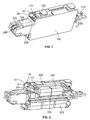
- Figure 1 is a three dimensional representation of the voice splitter according to one implementation of this utility model, where the door panel 110 is shown in the open position.
- a voice splitter is revealed. As shown in figure 1 , that voice splitter consists mainly of a circuit board 200, an insulation housing 100 and a gas discharge tube 201.
- the insulation housing 100 is positioned over the circuit board 200, being for the purpose of sealing in the electronic components on that circuit board 200.
- the gas discharge tube 201 is mounted on the circuit board 200, and is contained within the insulation housing 100.
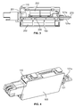
- Figure 4 is a three dimensional representation of the voice splitter according to one implementation of this utility model, where the door panel 110 is shown in the closed position.
- observation window 101 on the insulation housing 100 in a position close to the gas discharge tube 201; additionally there is a door panel 110 that can be opened and closed provided on the insulation housing 100, which is for the purpose of opening and closing the observation window 101.
- Figure 2 is a representation of the internal circuit board 200 and modular electronic function components 202 of the voice splitter shown in figure 1 .
- Figure 3 is the side view of the voice splitter shown in figure 2 .
- the door panel 110 is pivotally installed on the insulation housing 100, allowing it to open and close by rotation.
- pivot shaft 112 formed on the door panel 110, there being a pivot hole formed in the insulation housing 100, whereby the pivot shaft 112 fits into the pivot hole, thus allowing the door panel 110 to open and close by rotation.
- this utility model is not limited to the implementation shown in the diagrams, and it is possible to mount the door panel in a sliding arrangement on the insulation housing, sliding the door panel also allowing opening and closing of the observation window.
- a number of modular electronic function components 202 are mounted on the circuit board 200, these modular electronic function components 202 being distributed over both sides of the aforementioned circuit board 200, in addition to being contained within the insulation housing 100. In this manner, by applying modular design to the electronic components, space has been saved very effectively and assembly made more convenient.
- the circuit board 200 has an input terminal 210 for the purpose of inputting a voice signal and an output terminal 220 for the purpose of outputting a voice signal.
- the insulation housing 100 possesses a first terminal section 121 and a second terminal section 122 opposite the first terminal section 121; additionally the aforementioned input terminal 210 is located at the first terminal section 121 and the aforementioned output terminal 220 is located at the second terminal section 122 and are exposed externally.
- a pair of elastic clips 121a are formed on the first terminal section 121 of the insulation housing 100, this pair of elastic clips 121a being positioned on both sides of the aforementioned circuit board 200, allowing clipping onto the voice separator assembly module when inserted into its terminal; additionally, when the first terminal section 121 of the voice splitter is clipped onto such a voice separator assembly module when inserted into its terminal, the input terminal 210 of the aforementioned circuit board 200 forms an electrical contact with the corresponding terminal within the voice splitter assembly module (not shown).
- a wire connector cap 300 provided on the second terminal section 122 of the insulation housing 100, the wire connector cap 300 possessing a U-shaped slot 320, the output terminal 220 of the aforementioned circuit board 200 being located in that U-shaped slot 320, allowing it to grip the conductive wire (not shown) in the U-shaped slot 320 creating an electrical connection.
- the wire connector cap 300 it is possible to install the conductive wire in the wire connector cap 300 using a KRONE wiring tool, thus simplifying the process employed by operatives.
- the voice splitter relies on a compact paired wire voice splitter structure.
- tail end wire connector cap (otherwise known as a connector) 300 of the voice splitter relies on the patented KRONE LSA-PLUS IDC design, a design which allows the KRONE wiring tool to be used for the installation of the wire in this wire connector cap 300; this tool is generally used in wiring KRONE modules, and this voice splitter is specifically for installation on KRONE modules; as a result of this, only one cabling installation tool and one cabling installation process are necessary, thus simplifying the process employed by operatives.
- a conductive wire constraining channel 102 formed in the insulation housing 100, which constrains the conductive wire electrically connected to the output terminal 220 of the circuit board 200.
- that constraining channel 102 is bounded by the side panels of the insulation housing 100 and the outer wall of the insulation housing 100. This aids in conductive wire organisation, preventing the conductive wires from becoming tangled.
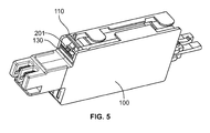
- Figure 5 is a three dimensional representation of the voice splitter according to another implementation of this utility model.
- thermochromic coating layer 130 the colour of which changes when exposed to heat, coated on the outer wall of the insulation housing 100 near the gas discharge tube 201.
- the gas discharge tube 201 is activated and causes a movement which protects the product from being damaged by the aforementioned dangers.
- the gas discharge tube 201 is subjected to all the energy created by such dangers, resulting in the gas discharge tube 201 accumulating thermal energy and increasing in temperature, the temperature of the insulation housing adjacent to the gas discharge tube 201 also increasing, therefore the colour of the thermochromic coating layer 130 coated on the external housing also changes.
- thermochromic material must first take into consideration the normal working temperature range, for instance the colour should not change between -40°C and 70°C, the colour only changing once a certain temperature has been exceeded, for instance when a temperature of 80°C is exceeded, with the colour change becoming greater as the temperature increases.
- thermochromic coating material allows the product operator to determine during maintenance whether or not the product has been endangered on the basis of changes to the colour of the thermochromic coating layer on the external housing of the product, thus this has a protective function, the extent of the colour change being an indication of the extent of the danger of damage to which it has been exposed, thus giving an indication of whether or not the function of the product in question requires testing and as to whether or not it requires replacement.
- thermochromic coating layer 130 may also be coated directly onto the outer wall of the door panel 110.
- a type of voice splitter comprising: a circuit board 200; an insulation housing 100 provided on the circuit board 200; and a gas discharge tube 201 mounted on the circuit board 200 and contained within the insulation housing 100.
- a thermochromic coating layer 130 the colour of which changes when exposed to heat, is coated on the outer wall of the insulation housing 100 near the gas discharge tube 201.
- the aforementioned voice splitter may be a single pair type VDSL2 voice splitter.
Landscapes
- Casings For Electric Apparatus (AREA)
- Insulating Bodies (AREA)
Abstract
Description
- This utility model relates to a type of voice splitter, in particular it relates to a type of single pair type VDSL2 voice splitter.
- In current technology, voice splitters mainly consist of an insulation housing and a number of electronic components contained within said insulation housing. These electronic components include at least one gas discharge tube (GDT). When a lightning strike or alternating current is sensed or there is a spike in electrical power or other such danger, the GDT is activated and causes a movement which protects the voice splitter product from being damaged by the aforementioned dangers. At the same time as the GDT is activated, the energy created by such dangers passes to the GDT, resulting in the GDT accumulating thermal energy and increasing in temperature; if the temperature exceeds a pre-set value, the GDT will fail.
- Where current technology is concerned, the GDT is contained within the insulation housing, thus it is not possible to observe from the exterior whether or not this has failed. When carrying out servicing or maintenance, specialist inspection equipment is required before it is possible to establish whether or not the GDT has failed, and due to this, checking of whether or not the GDT has failed is not convenient, increasing the difficulty of servicing and maintenance.
- The aims of this utility model are to resolve at least one aspect of the problems and drawbacks that exist in current technology mentioned above.
- One aim of this utility model is to provide a type of voice splitter that allows convenient observation of whether or not the GDT has failed.
- One aspect of this invention is to provide a type of voice splitter, comprising: a circuit board; an insulation housing provided on the circuit board; and a gas discharge tube mounted on the circuit board and contained within the insulation housing, whereby an observation window is formed in a location on the insulation housing near the gas discharge tube, and a door panel is provided on the insulation housing which may be opened and closed, for the purpose of opening and closing the aforementioned observation window.
- According to an example of an implementation of this invention, a thermochromic coating layer, the colour of which changes when exposed to heat, is coated either on the outer wall of the insulation housing near the gas discharge tube or on the outer wall of the door panel.
- According to another example of an implementation of this invention, the door panel is pivotally mounted on the insulation housing, allowing it to be opened or closed by rotating it.
- According to another example of an implementation of this invention, there is a pivot shaft formed in the door panel, and there is a pivot hole formed in the insulation housing, the aforementioned pivot shaft fitting into that pivot hole.
- According to another example of an implementation of this invention, there is an elastic catch formed on the aforementioned door panel, there being a recess formed in the insulation housing, the flexible catch clipping into that recess; wherein the elastic catch is captured within the recess when the door panel is in the closed position, thus retaining the door panel in the closed position.
- According to another example of an implementation of this invention, a number of modular electronic function components are mounted on the circuit board, these modular electronic function components being distributed over both sides of the aforementioned circuit board, in addition to being contained within the insulation housing.
- According to another example of an implementation of this invention, the circuit board has an input terminal for the purpose of inputting a voice signal and an output terminal or the purpose of outputting a voice signal.
- According to another example of an implementation of this invention, the insulation housing possesses a first terminal section and a second terminal section opposite the first terminal section; additionally the aforementioned input terminal is located in the position of the first terminal section and the aforementioned output terminal is located in the position of the second terminal section and they are exposed externally.
- According to another example of an implementation of this invention, a pair of elastic clips is formed on the first terminal section of the insulation housing, this pair of elastic clips being positioned on both sides of the aforementioned circuit board, allowing clipping onto the voice separator assembly module when inserted into its terminal; additionally, when the first terminal section of the voice splitter is clipped onto such a voice separator assembly module when inserted into its terminal, the input terminal of the aforementioned circuit board forms an electrical contact with the corresponding terminal within the voice splitter assembly module.
- According to another example of an implementation of this invention, there is a wire connector cap provided on the second terminal section of the insulation housing, the wire connector cap possessing a U-shaped slot, the output terminal of the aforementioned circuit board being located in that U-shaped slot, allowing it to grip the conductive wire within the U-shaped slot and creating an electrical connection.
- According to another example of an implementation of this invention, there is a conductive wire constraining channel formed in the insulation housing, which constrains the conductive wire electrically connected to the output terminal of the circuit board.
- According to another example of an implementation of this invention, the voice splitter is a single pair type VDSL2 voice splitter.
- Another aspect of this invention is to provide a type of voice splitter, comprising: a circuit board; an insulation housing provided on the circuit board; and a gas discharge tube mounted on the circuit board and contained within the insulation housing, whereby a thermochromic coating layer, the colour of which changes when exposed to heat, is coated on the outer wall of the insulation housing near the gas discharge tube.
- In all of the above mentioned implementations of this utility model, due to there being an observation window which can be opened and closed which is located on the insulation housing in a position near to the gas discharge tube, when this observation window is opened, it is possible to observe visually whether or not the gas discharge tube has failed, which is convenient in terms of servicing and maintenance.
- Apart from this, in an application of this invention, due to there being a thermochromic coating layer, the colour of which changes when exposed to heat, coated either on the outer wall of the insulation housing near the gas discharge tube or the outer wall of the door panel, it is possible to see by observing changes to the colour of the thermochromic coating layer whether the gas discharge tube has failed, which is convenient in terms of servicing and maintenance.
- The description of the utility model within the following text when taken in conjunction with the appended diagrams makes the other aims and advantages of this utility model easier to see and appreciate, thus aiding in providing a more complete understanding of this utility model.
-
-
Figure 1 is a three dimensional representation of the voice splitter according to one implementation of this utility model, where the door panel is shown in the open position; -
Figure 2 is a representation of the internal modular electronic function components and circuit board of the voice splitter shown infigure 1 ; -
Figure 3 is a side view of the voice splitter shown infigure 2 ; -
Figure 4 is a three dimensional representation of the voice splitter according to one implementation of this utility model, where the door panel is shown in the closed position; and -
Figure 5 is a three dimensional representation of the voice splitter according to another implementation of this utility model. - The following implementation, taken in conjunction with the appended diagrams, provides a more detailed description of the technical scheme according to this utility model. Identical or similar labelling in the appended diagrams refers to identical or similar components in the description. The aim of the following description of an implementation of this utility model given with reference to the appended diagrams is for the purpose of providing an understanding of the concepts of this utility model in the form of examples, and thus should not be understood as constituting any type of restriction to this utility model.
- Apart from this, in the following detailed descriptions, for convenience sake, many specific details are described in order to facilitate an overall understanding of the facets of the utility model here disclosed. But it is of course clear, that one or more implementations could be realised even in the absence of these specific details. Under other circumstances, known structures and assemblages could be represented graphically in order to simplify the appended diagrams.
- One of the overall technical concepts embodied in this utility model, is that it provides a voice splitter, comprising: a circuit board; an insulation housing provided on the circuit board; and a gas discharge tube mounted on the circuit board and contained within the insulation housing.
- An observation window is formed in a location on the insulation housing near the gas discharge tube, and a door panel is provided on the insulation housing which may be opened and closed, for the purpose of opening and closing the aforementioned observation window.
-
Figure 1 is a three dimensional representation of the voice splitter according to one implementation of this utility model, where thedoor panel 110 is shown in the open position. - In one example of an implementation of this invention, a voice splitter is revealed. As shown in
figure 1 , that voice splitter consists mainly of acircuit board 200, aninsulation housing 100 and agas discharge tube 201. - As shown in
figure 1 , theinsulation housing 100 is positioned over thecircuit board 200, being for the purpose of sealing in the electronic components on thatcircuit board 200. Thegas discharge tube 201 is mounted on thecircuit board 200, and is contained within theinsulation housing 100. -
Figure 4 is a three dimensional representation of the voice splitter according to one implementation of this utility model, where thedoor panel 110 is shown in the closed position. - As is clearly shown in
figures 1 and4 , in one implementation of this invention, there is anobservation window 101 on theinsulation housing 100 in a position close to thegas discharge tube 201; additionally there is adoor panel 110 that can be opened and closed provided on theinsulation housing 100, which is for the purpose of opening and closing theobservation window 101. -
Figure 2 is a representation of theinternal circuit board 200 and modularelectronic function components 202 of the voice splitter shown infigure 1 .Figure 3 is the side view of the voice splitter shown infigure 2 . - As shown in
figures 1 to 3 , in the diagrammatic depiction of this implementation, thedoor panel 110 is pivotally installed on theinsulation housing 100, allowing it to open and close by rotation. - As shown in
figure 2 , there is apivot shaft 112 formed on thedoor panel 110, there being a pivot hole formed in theinsulation housing 100, whereby thepivot shaft 112 fits into the pivot hole, thus allowing thedoor panel 110 to open and close by rotation. - However it should be made aware, this utility model is not limited to the implementation shown in the diagrams, and it is possible to mount the door panel in a sliding arrangement on the insulation housing, sliding the door panel also allowing opening and closing of the observation window.
- As shown in
figures 1 to 4 , in the implementation shown in the diagrams, there is anelastic catch 111 formed on theaforementioned door panel 110, there being a recess formed in theinsulation housing 100, theflexible catch 111 clipping into that recess. In this manner, when thedoor panel 110 is in the closed position, theelastic catch 111 is captured within the recess, thus retaining thedoor panel 110 in the closed position. - In an example of an implementation of this invention, as shown in
figures 2 and3 , a number of modularelectronic function components 202 are mounted on thecircuit board 200, these modularelectronic function components 202 being distributed over both sides of theaforementioned circuit board 200, in addition to being contained within theinsulation housing 100. In this manner, by applying modular design to the electronic components, space has been saved very effectively and assembly made more convenient. - As shown in
figures 1 to 4 , in an example of an implementation of this utility model, thecircuit board 200 has aninput terminal 210 for the purpose of inputting a voice signal and anoutput terminal 220 for the purpose of outputting a voice signal. - In the implementation shown by the diagrams, indicated by
figures 1 to 4 , theinsulation housing 100 possesses afirst terminal section 121 and asecond terminal section 122 opposite thefirst terminal section 121; additionally theaforementioned input terminal 210 is located at thefirst terminal section 121 and theaforementioned output terminal 220 is located at thesecond terminal section 122 and are exposed externally. - As shown in
figures 1 to 4 , in one example of an implementation of this invention, a pair ofelastic clips 121a are formed on thefirst terminal section 121 of theinsulation housing 100, this pair ofelastic clips 121a being positioned on both sides of theaforementioned circuit board 200, allowing clipping onto the voice separator assembly module when inserted into its terminal; additionally, when thefirst terminal section 121 of the voice splitter is clipped onto such a voice separator assembly module when inserted into its terminal, theinput terminal 210 of theaforementioned circuit board 200 forms an electrical contact with the corresponding terminal within the voice splitter assembly module (not shown). - As shown in
figures 1 to 4 , in an example of an implementation of this invention, there is awire connector cap 300 provided on thesecond terminal section 122 of theinsulation housing 100, thewire connector cap 300 possessing a U-shapedslot 320, theoutput terminal 220 of theaforementioned circuit board 200 being located in that U-shapedslot 320, allowing it to grip the conductive wire (not shown) in the U-shapedslot 320 creating an electrical connection. In this manner, it is possible to install the conductive wire in thewire connector cap 300 using a KRONE wiring tool, thus simplifying the process employed by operatives. - With the implementation shown in the diagrams, the voice splitter relies on a compact paired wire voice splitter structure. To be specific, tail end wire connector cap (otherwise known as a connector) 300 of the voice splitter relies on the patented KRONE LSA-PLUS IDC design, a design which allows the KRONE wiring tool to be used for the installation of the wire in this
wire connector cap 300; this tool is generally used in wiring KRONE modules, and this voice splitter is specifically for installation on KRONE modules; as a result of this, only one cabling installation tool and one cabling installation process are necessary, thus simplifying the process employed by operatives. - In the implementation shown by
figure 1 , there is a conductivewire constraining channel 102 formed in theinsulation housing 100, which constrains the conductive wire electrically connected to theoutput terminal 220 of thecircuit board 200. In the implementation shown byfigure 1 , that constrainingchannel 102 is bounded by the side panels of theinsulation housing 100 and the outer wall of theinsulation housing 100. This aids in conductive wire organisation, preventing the conductive wires from becoming tangled. -
Figure 5 is a three dimensional representation of the voice splitter according to another implementation of this utility model. - The main difference between the voice splitter shown in
figure 5 and the voice splitter shown infigures 1 to 4 is that: in the voice splitter shown infigure 5 , there is athermochromic coating layer 130, the colour of which changes when exposed to heat, coated on the outer wall of theinsulation housing 100 near thegas discharge tube 201. - During operation, when a lightning strike or alternating current is sensed or there is a spike in electrical power or other such danger is transmitted to the
gas discharge tube 201, thegas discharge tube 201 is activated and causes a movement which protects the product from being damaged by the aforementioned dangers. At the same time as thegas discharge tube 201 is activated, thegas discharge tube 201 is subjected to all the energy created by such dangers, resulting in thegas discharge tube 201 accumulating thermal energy and increasing in temperature, the temperature of the insulation housing adjacent to thegas discharge tube 201 also increasing, therefore the colour of thethermochromic coating layer 130 coated on the external housing also changes. The choice of thermochromic material must first take into consideration the normal working temperature range, for instance the colour should not change between -40°C and 70°C, the colour only changing once a certain temperature has been exceeded, for instance when a temperature of 80°C is exceeded, with the colour change becoming greater as the temperature increases. The adoption of such thermochromic coating material, allows the product operator to determine during maintenance whether or not the product has been endangered on the basis of changes to the colour of the thermochromic coating layer on the external housing of the product, thus this has a protective function, the extent of the colour change being an indication of the extent of the danger of damage to which it has been exposed, thus giving an indication of whether or not the function of the product in question requires testing and as to whether or not it requires replacement. - Apart from this, the voice splitter shown in
figure 5 is basically the same as the voice splitter shown infigures 1 to 4 , and for the sake of brevity, similar content will not be repeated. However it should be made aware that, this invention is not restricted to the implementations shown in the diagrams, for instance, thethermochromic coating layer 130 may also be coated directly onto the outer wall of thedoor panel 110. - In another implementation of this invention, a type of voice splitter is revealed, comprising: a
circuit board 200; aninsulation housing 100 provided on thecircuit board 200; and agas discharge tube 201 mounted on thecircuit board 200 and contained within theinsulation housing 100. Whereby athermochromic coating layer 130, the colour of which changes when exposed to heat, is coated on the outer wall of theinsulation housing 100 near thegas discharge tube 201. - In an example of an implementation of this invention, the aforementioned voice splitter may be a single pair type VDSL2 voice splitter.
- As can be appreciated by a technician in this field, the implementations described above are simply provided as examples, and it would be possible for a technician in this field to make improvements to these, and changes may be made freely to the structures described in these implementations where these do not conflict with the structure or principles embodied herein.
- Although description of the implementations is provided in conjunction with the appended diagrams, however the implementations described and revealed in the appended diagrams are purely typical examples of preferred implementations, and should not be understood as limiting this utility model.
- Although certain examples representative of the overall concepts that this utility model embodies have been revealed and described, as may be understood by a general technician in this field, where they not depart from the principles and essence of the overall concepts reflected by this utility model, it would be possible to carry out modification of these implementations, the scope of protection afforded to this utility model being based on the claims and their equivalents.
- It should be noted, that the wording "include" does not exclude other components or steps, the wording "a" or "one" does not exclude more than one. Additionally, the numbering of any component should not be understood as limiting the scope of this utility model.
Claims (13)
- A voice splitter, comprising:a circuit board (200);an insulation housing (100) provided on the circuit board (200); anda gas discharge tube (201) mounted on the circuit board (200) and contained within the insulation housing (100),whereby an observation window (101) is formed in a location on the insulation housing (100) near the gas discharge tube (201), anda door panel (110) is provided on the insulation housing (100) which may be opened and closed,for the purpose of opening and closing the aforementioned observation window (101).
- The voice splitter according to claim 1,
whereby a thermochromic coating layer (130), the colour of which changes when exposed to heat, is coated either on the outer wall of the insulation housing (100) near the gas discharge tube (201) or on the outer wall of the door panel (110). - The voice splitter according to claims 1 or 2,
whereby the door panel (110) is pivotally mounted on the insulation housing (100), allowing it to be opened or closed by rotating it. - The voice splitter according to claim 3,
whereby there is a pivot shaft (112) formed in the door panel (110), there being a pivot hole formed in the insulation housing (100), the aforementioned pivot shaft (112) fitting into that pivot hole. - The voice splitter according to claim 3,
whereby there is an elastic catch (111) formed on the aforementioned door panel (110), there being a recess formed in the insulation housing (100), the flexible catch (111) clipping into that recess;
wherein the elastic catch (111) is captured within the recess when the door panel (110) is in the closed position, thus retaining the door panel (110) in the closed position. - The voice splitter according to claims 1 or 2,
whereby a number of modular electronic function components (202) are mounted on the circuit board (200), these modular electronic function components (202) being distributed over both sides of the aforementioned circuit board (200), in addition to being contained within the insulation housing (100). - The voice splitter according to claim 6,
whereby the circuit board (200) has an input terminal (210) for the purpose of inputting a voice signal and an output terminal (220) for the purpose of outputting a voice signal. - The voice splitter according to claim 7,
whereby the insulation housing (100) possesses a first terminal section (121) and a second terminal section (122) opposite the first terminal section (121); additionally the aforementioned input terminal (210) is located in the position of the first terminal section (121) and the aforementioned output terminal (220) is located in the position of the second terminal section (122) and they are exposed externally. - The voice splitter according to claim 8,
whereby a pair of elastic clips (121a) is formed on the first terminal section (121) of the insulation housing (100), this pair of elastic clips (121a) being positioned on both sides of the aforementioned circuit board (200), allowing clipping onto the voice separator assembly module when inserted into its terminal; additionally,
when the first terminal section (121) of the voice splitter is clipped onto the voice separator assembly module when inserted into its terminal, the input terminal (210) of the aforementioned circuit board (200) forms an electrical contact with the corresponding terminal within the voice splitter assembly module. - The voice splitter according to claim 9,
whereby there is a wire connector cap (300) provided on the second terminal section (122) of the insulation housing (100), the wire connector cap (300) possessing a U-shaped slot (320), the output terminal (220) of the aforementioned circuit board (200) being located in that U-shaped slot (320), allowing it to grip the conductive wire within the U-shaped slot (320) and creating an electrical connection. - The voice splitter according to claim 10,
whereby there is a conductive wire constraining channel (102) formed in the insulation housing (100), which constrains the conductive wire electrically connected to the output terminal (220) of the circuit board (200). - The voice splitter according to claim 1, whereby that voice splitter is a single pair type VDSL2 voice splitter.
- A voice splitter, comprising:a circuit board (200);an insulation housing (100) provided on the circuit board (200); anda gas discharge tube (201) mounted on the circuit board (200) and contained within the insulation housing (100),whereby a thermochromic coating layer (130), the colour of which changes when exposed to heat, is coated on the outer wall of the insulation housing (100) near the gas discharge tube (201).
Applications Claiming Priority (1)
| Application Number | Priority Date | Filing Date | Title |
|---|---|---|---|
| CN201520424509.9U CN204857178U (en) | 2015-06-18 | 2015-06-18 | speech separator |
Publications (1)
| Publication Number | Publication Date |
|---|---|
| EP3109954A1 true EP3109954A1 (en) | 2016-12-28 |
Family
ID=54747706
Family Applications (1)
| Application Number | Title | Priority Date | Filing Date |
|---|---|---|---|
| EP16175359.5A Withdrawn EP3109954A1 (en) | 2015-06-18 | 2016-06-20 | A voice splitter |
Country Status (3)
| Country | Link |
|---|---|
| EP (1) | EP3109954A1 (en) |
| CN (1) | CN204857178U (en) |
| AU (1) | AU2016204139A1 (en) |
Cited By (1)
| Publication number | Priority date | Publication date | Assignee | Title |
|---|---|---|---|---|
| DE102018116208A1 (en) * | 2018-07-04 | 2020-01-09 | Phoenix Contact Gmbh & Co. Kg | Surge protection device |
Families Citing this family (2)
| Publication number | Priority date | Publication date | Assignee | Title |
|---|---|---|---|---|
| CN107229005A (en) * | 2017-05-24 | 2017-10-03 | 贵州电网有限责任公司电力科学研究院 | A kind of accurate quick method for determining GIS device discharge accident position |
| CN107202943A (en) * | 2017-05-24 | 2017-09-26 | 贵州电网有限责任公司电力科学研究院 | The method that GIS device discharge accident reason is quickly determined using heat indicating paint and digital radial |
Citations (4)
| Publication number | Priority date | Publication date | Assignee | Title |
|---|---|---|---|---|
| US5684667A (en) * | 1996-05-08 | 1997-11-04 | Hsieh; King-Long | Full failure protector module |
| EP0947836A2 (en) * | 1998-03-31 | 1999-10-06 | Tektronix, Inc. | Instrument with installation-evident accessory modules |
| DE202005009123U1 (en) * | 2005-05-18 | 2005-09-22 | Dehn + Söhne Gmbh + Co. Kg | Overvoltage disconnection device especially for telecommunications has protection and fault recognition units with visual color display according to device condition |
| TW201249289A (en) * | 2011-05-31 | 2012-12-01 | Kuo-Ching Chiang | Thermal color-changeable mobile phone |
-
2015
- 2015-06-18 CN CN201520424509.9U patent/CN204857178U/en not_active Expired - Fee Related
-
2016
- 2016-06-20 EP EP16175359.5A patent/EP3109954A1/en not_active Withdrawn
- 2016-06-20 AU AU2016204139A patent/AU2016204139A1/en not_active Abandoned
Patent Citations (5)
| Publication number | Priority date | Publication date | Assignee | Title |
|---|---|---|---|---|
| US5684667A (en) * | 1996-05-08 | 1997-11-04 | Hsieh; King-Long | Full failure protector module |
| EP0947836A2 (en) * | 1998-03-31 | 1999-10-06 | Tektronix, Inc. | Instrument with installation-evident accessory modules |
| DE202005009123U1 (en) * | 2005-05-18 | 2005-09-22 | Dehn + Söhne Gmbh + Co. Kg | Overvoltage disconnection device especially for telecommunications has protection and fault recognition units with visual color display according to device condition |
| TW201249289A (en) * | 2011-05-31 | 2012-12-01 | Kuo-Ching Chiang | Thermal color-changeable mobile phone |
| CN202799423U (en) * | 2011-05-31 | 2013-03-13 | 江国庆 | Hand-held communication device capable of changing color thermally |
Non-Patent Citations (1)
| Title |
|---|
| DATABASE WPI Week 201316, Derwent World Patents Index; AN 2013-C64914 * |
Cited By (1)
| Publication number | Priority date | Publication date | Assignee | Title |
|---|---|---|---|---|
| DE102018116208A1 (en) * | 2018-07-04 | 2020-01-09 | Phoenix Contact Gmbh & Co. Kg | Surge protection device |
Also Published As
| Publication number | Publication date |
|---|---|
| AU2016204139A1 (en) | 2017-01-12 |
| CN204857178U (en) | 2015-12-09 |
Similar Documents
| Publication | Publication Date | Title |
|---|---|---|
| US9380721B2 (en) | Cable clip for module electronics | |
| EP2806277A1 (en) | Closure | |
| EP3109954A1 (en) | A voice splitter | |
| KR20080103422A (en) | inverter | |
| US10182495B2 (en) | Ground terminal for an electronic device | |
| CA2775262C (en) | Intersystem grounding bridge and system | |
| US6734355B1 (en) | Ground connector | |
| US7140926B2 (en) | Telecommunications terminal module | |
| US20170141556A1 (en) | Riser glove, enclosure glove and strain releasing connectors | |
| CN109149230A (en) | Waterproof terminal plate | |
| US9234914B2 (en) | Apparatus to verify an electrically safe work condition | |
| WO2005027160A2 (en) | Arrangement for monitoring electric devices on stray light arcs | |
| CN207542737U (en) | A kind of Anti-creepage type bus duct | |
| US11381074B2 (en) | Electrical protection system and method for a high-voltage direct current system | |
| JP5869060B2 (en) | Ground resistance measurement terminal device | |
| EP1710868A2 (en) | Sealing element for terminal portions of multipolar cables | |
| EP2787584A1 (en) | Electrical switchgear with a built-in connection system for connecting measuring equipment and injecting and sensing low-frequency and high-frequency signals | |
| JP4401314B2 (en) | Bypass connection device | |
| ITMI981279A1 (en) | DEVICE FOR CABLE TIGHTENING AND DRAINAGE TOWARDS THE EDGE CURRENTS INDUCED ON SHIELDED CABLES WHEN CROSSING A | |
| WO2015117743A1 (en) | Perfected device for grounding cables, in particular coaxial cables | |
| KR200371605Y1 (en) | A switch board case with a support box for cable guide | |
| RU2006120C1 (en) | Cable stuffing arrangement | |
| DK154381B (en) | CONNECTION AND BRANCHING DASE TO TELECABLES | |
| US5503567A (en) | Termination module | |
| NO20060271L (en) | Cable end unit |
Legal Events
| Date | Code | Title | Description |
|---|---|---|---|
| PUAI | Public reference made under article 153(3) epc to a published international application that has entered the european phase |
Free format text: ORIGINAL CODE: 0009012 |
|
| STAA | Information on the status of an ep patent application or granted ep patent |
Free format text: STATUS: THE APPLICATION HAS BEEN PUBLISHED |
|
| AK | Designated contracting states |
Kind code of ref document: A1 Designated state(s): AL AT BE BG CH CY CZ DE DK EE ES FI FR GB GR HR HU IE IS IT LI LT LU LV MC MK MT NL NO PL PT RO RS SE SI SK SM TR |
|
| AX | Request for extension of the european patent |
Extension state: BA ME |
|
| RIN1 | Information on inventor provided before grant (corrected) |
Inventor name: NEUMETZLER, HEIKO Inventor name: ZHU, HUAISHENG Inventor name: FAN, WENYONG Inventor name: LIU, YAN Inventor name: ZHANG, WEILI Inventor name: ZHANG, LUJUN |
|
| RAP1 | Party data changed (applicant data changed or rights of an application transferred) |
Owner name: ADC TELECOMMUNICATIONS (SHANGHAI) DISTRIBUTION CO. Owner name: TYCO ELECTRONICS RAYCHEM GMBH |
|
| STAA | Information on the status of an ep patent application or granted ep patent |
Free format text: STATUS: THE APPLICATION IS DEEMED TO BE WITHDRAWN |
|
| 18D | Application deemed to be withdrawn |
Effective date: 20170629 |