EP3109828A1 - Vehicle-mounted recognition device - Google Patents
Vehicle-mounted recognition device Download PDFInfo
- Publication number
- EP3109828A1 EP3109828A1 EP15749369.3A EP15749369A EP3109828A1 EP 3109828 A1 EP3109828 A1 EP 3109828A1 EP 15749369 A EP15749369 A EP 15749369A EP 3109828 A1 EP3109828 A1 EP 3109828A1
- Authority
- EP
- European Patent Office
- Prior art keywords
- image
- disparity
- concealment
- standard
- target
- Prior art date
- Legal status (The legal status is an assumption and is not a legal conclusion. Google has not performed a legal analysis and makes no representation as to the accuracy of the status listed.)
- Granted
Links
Images






Classifications
-
- G—PHYSICS
- G06—COMPUTING OR CALCULATING; COUNTING
- G06V—IMAGE OR VIDEO RECOGNITION OR UNDERSTANDING
- G06V20/00—Scenes; Scene-specific elements
- G06V20/50—Context or environment of the image
- G06V20/56—Context or environment of the image exterior to a vehicle by using sensors mounted on the vehicle
- G06V20/58—Recognition of moving objects or obstacles, e.g. vehicles or pedestrians; Recognition of traffic objects, e.g. traffic signs, traffic lights or roads
-
- G—PHYSICS
- G01—MEASURING; TESTING
- G01C—MEASURING DISTANCES, LEVELS OR BEARINGS; SURVEYING; NAVIGATION; GYROSCOPIC INSTRUMENTS; PHOTOGRAMMETRY OR VIDEOGRAMMETRY
- G01C3/00—Measuring distances in line of sight; Optical rangefinders
- G01C3/02—Details
- G01C3/06—Use of electric means to obtain final indication
-
- G—PHYSICS
- G06—COMPUTING OR CALCULATING; COUNTING
- G06V—IMAGE OR VIDEO RECOGNITION OR UNDERSTANDING
- G06V10/00—Arrangements for image or video recognition or understanding
- G06V10/20—Image preprocessing
- G06V10/25—Determination of region of interest [ROI] or a volume of interest [VOI]
-
- G—PHYSICS
- G06—COMPUTING OR CALCULATING; COUNTING
- G06V—IMAGE OR VIDEO RECOGNITION OR UNDERSTANDING
- G06V10/00—Arrangements for image or video recognition or understanding
- G06V10/40—Extraction of image or video features
- G06V10/62—Extraction of image or video features relating to a temporal dimension, e.g. time-based feature extraction; Pattern tracking
-
- G—PHYSICS
- G06—COMPUTING OR CALCULATING; COUNTING
- G06V—IMAGE OR VIDEO RECOGNITION OR UNDERSTANDING
- G06V10/00—Arrangements for image or video recognition or understanding
- G06V10/70—Arrangements for image or video recognition or understanding using pattern recognition or machine learning
- G06V10/74—Image or video pattern matching; Proximity measures in feature spaces
-
- H—ELECTRICITY
- H04—ELECTRIC COMMUNICATION TECHNIQUE
- H04N—PICTORIAL COMMUNICATION, e.g. TELEVISION
- H04N13/00—Stereoscopic video systems; Multi-view video systems; Details thereof
- H04N13/10—Processing, recording or transmission of stereoscopic or multi-view image signals
- H04N13/106—Processing image signals
- H04N13/128—Adjusting depth or disparity
-
- H—ELECTRICITY
- H04—ELECTRIC COMMUNICATION TECHNIQUE
- H04N—PICTORIAL COMMUNICATION, e.g. TELEVISION
- H04N13/00—Stereoscopic video systems; Multi-view video systems; Details thereof
- H04N13/20—Image signal generators
- H04N13/204—Image signal generators using stereoscopic image cameras
- H04N13/239—Image signal generators using stereoscopic image cameras using two two-dimensional [2D] image sensors having a relative position equal to or related to the interocular distance
-
- G—PHYSICS
- G06—COMPUTING OR CALCULATING; COUNTING
- G06V—IMAGE OR VIDEO RECOGNITION OR UNDERSTANDING
- G06V2201/00—Indexing scheme relating to image or video recognition or understanding
- G06V2201/07—Target detection
-
- H—ELECTRICITY
- H04—ELECTRIC COMMUNICATION TECHNIQUE
- H04N—PICTORIAL COMMUNICATION, e.g. TELEVISION
- H04N13/00—Stereoscopic video systems; Multi-view video systems; Details thereof
- H04N2013/0074—Stereoscopic image analysis
- H04N2013/0081—Depth or disparity estimation from stereoscopic image signals
-
- H—ELECTRICITY
- H04—ELECTRIC COMMUNICATION TECHNIQUE
- H04N—PICTORIAL COMMUNICATION, e.g. TELEVISION
- H04N7/00—Television systems
- H04N7/18—Closed-circuit television [CCTV] systems, i.e. systems in which the video signal is not broadcast
Definitions
- the present invention relates to a vehicle-mounted recognition device which recognizes an object through image processing.
- a vehicle-mounted image recognition system which recognizes surrounding vehicles and running lane through a vehicle-mounted camera to prevent an accident from happening.
- the recognition target objects are diversified, and besides the vehicle, a pedestrian and a road speed sign are included as the recognition target.
- a stereo camera which measures a distance based on the principle of triangulation using two cameras.
- corresponding points of two cameras in a horizontal direction are obtained, and displacement therebetween is set as a disparity.
- a distance from the subject vehicle to the corresponding points is calculated based on the disparity and is held as a distance image.
- the object can be recognized using appearance pattern information itself captured by the camera.
- PTL 1 discloses a technique of recognizing a sign using the stereo camera.
- an area of the sign is first estimated in the distance image, an approximate size of the sign is estimated from the distance, and then a template matching is performed according to the size so as to recognize the sign.
- PTL 2 discloses a vehicle-mounted image recognition system using a plurality of cameras (not limited to the stereo camera) in which, when the object of the detection target cannot be recognized due to a stain of a lens in one camera, a recognition process is performed by another camera to find out the object of the detection target.
- a recognition process is performed by another camera to find out the object of the detection target.
- the object can be found in the other image, so that detection missing can be prevented.
- the detection missing can be prevented by recognizing both images.
- the recognition process is respectively performed on the plurality of images, a lot of processing time is taken compared to the recognition process which is performed on only one image.
- the invention has been made in view of the above problems, and an object thereof is to provide a vehicle-mounted recognition device which can recognize a target in a short processing time.
- a vehicle-mounted recognition device which recognizes a target from any one of a pair of images simultaneously captured by a pair of image capture units.
- the vehicle-mounted recognition device includes a disparity measurement unit which measures a disparity using the pair of images, an object information estimation unit which estimates a current position of the object from a past position of the object, a concealment determination unit which determines whether concealment of the target occurs in at least one of the pair of images based on a measurement result of the disparity measurement unit and an estimation result of the object information estimation unit, an image selection unit which selects an image, from which the target is recognizable, from the pair of images based on a determination result of the concealment determination unit, and an object recognition unit which recognizes the target using the selected image.
- FIG. 1 is a flowchart illustrating an exemplary process of an image recognition system using a stereo camera.
- the stereo camera is mounted in a vehicle, and includes a pair of right and left image capture units (cameras) which capture the front side of the vehicle.
- a right image and a left image are respectively acquired by the pair of image capture units (S101, S102).
- a distance up to an object captured by the principle of triangulation is measured based on a difference between appearance patterns in the right and left images.
- a disparity which is an index indicating a separation degree of the object on two image coordinates of the right and left images is obtained, and a disparity image is generated (S103).
- FIG. 2 is a diagram for describing a specific example of disparity deduction.
- any one of the right image and the left image is determined as an image serving as a standard, and the standard image is partitioned and divided into small rectangular block images.
- the image serving as a standard herein will be called as a standard image 201, and is set as a right image (IR(x, y)) in the following description if not otherwise specified.
- IR(x, y) right image
- an area matched with each rectangular block image is retrieved by a pixel length maxd in a horizontal direction (x direction) 203 from the other image 204.
- the other image thus retrieved is called a reference image 204, and is set as a left image (IL(x, y)) in the following description if not otherwise specified.
- (x, y) represents the image coordinates.
- argmax represents a function of outputting d (0 ⁇ d ⁇ maxd) causing the largest S.
- a relation between the disparity image coordinates u, v and the coordinates x, y of the standard image is set as the following equation (where, sx and sy represent horizontal and vertical block sizes).
- u x * sx
- v y * sy
- the disparity Dr may be used as a disparity image D as it is, but herein the disparity image D is generated as described below.
- the reference image is partitioned into blocks, and the retrieving is made in the horizontal direction with respect to the standard image.
- the retrieving direction is set to a direction opposed to the horizontal direction 203.
- Dl is obtained, and the final disparity image is obtained using an appropriate threshold Td as follows.
- D u v if Dr u v ⁇ Dl u ⁇ Dr u v , v ⁇ Td then Dr(u, v) else ⁇
- This process is called a right and left image check.
- the disparity image is generated, the block is created from the right image and the disparity image Dr is generated based on the right image, and the block is created from the left image and the disparity image Dl is generated based on the left image.
- the disparity image D is generated by comparing the disparity image Dr with the disparity image Dl (a disparity image generation unit).
- This method is used for suppressing a mismatching.
- " ⁇ " represents a state where the disparity is invalid. For example, in a case where an object is concealed by another object in front of the object in one image, it is not possible to obtain the disparity because there is no matched portion between the blocks at the time of the retrieving process.
- the determination of " ⁇ " is performed based on the size of S (x, y, d) which is minimized at the time of matching.
- the distance (Z) up to the object can be obtained by the following equation using the disparity, a focal distance (f) of a lens of the image capture unit, a pixel interval ( ⁇ ) of the capture element, and a baseline length (b) between the image capture units.
- Z b * f / D uo vo * ⁇
- an object information estimation process is performed in which narrowing is performed to find out an object (target) of a detection target (S104).
- a processing method for example, (1) near areas having a similar disparity are collected and labeled, and the areas are considered as one object. It is expected that the same object is assigned with the same label. (2) The approximated position of the detection target object is narrowed down from appearance pattern information. (3) When there is recognition information of the last frame, the current position is estimated from behavior of the subject vehicle based on the recognition information.
- a disparity label image in a case where the above (1) processing method is used is represented as L(u, v).
- object recognition for specifying an identity of the object is performed by analyzing the shape of the area assigned with the same label in L(u, v) with respect to the narrow-down area and the appearance pattern of the original standard image IR(x, y) (S105).
- the identity include a road sign, a pedestrian, a preceding vehicle, and the like.
- appearance information at a position (u, v) can be obtained directly from (Equation 2). The result is transferred to a display or a control device (S106).
- the detection target object Various objects are considered as the detection target object and, in this embodiment, the type of a road sign will be considered as a recognition target.
- the pattern displayed in the sign is necessarily recognized as 30 km/h, 40 km/h, or the like.
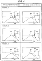
- FIG. 4 is a diagram illustrating an exemplary image in which the sign is invisible in the right image.
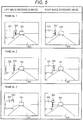
- FIG. 5 is a diagram illustrating an exemplary image in which the sign is invisible in the left image.
- FIG. 4 illustrates an example in which right and left images time-sequentially captured by the stereo camera are illustrated and an object 403 of the detection target is concealed by another object 402 in front thereof.
- the time-sequential images show an example in which the subject vehicle moves forward and the preceding vehicle 401 and the vehicle 402 on the right side also move forward in the same direction as the subject vehicle at a constant speed.
- Frame No. 1 to Frame No. 3 are sequentially captured in a predetermined time interval.
- An object drawn with rectangular and circle on the right side in each image indicates an example of a road sign 403.
- the road sign 403 is provided at the right end of a road 404, and displayed in both right and left images in Frame No. 1.
- the road sign is concealed by the shadow of the other vehicle 402 which moves forward together with the subject vehicle in the right image of Frame No. 2, and thus a portion of the road sign 403 becomes invisible.
- the entire road sign 403 gets out of the shadow of the shadow of the vehicle 402 and is visible in the left image of Frame No. 2.
- the sign 403 is concealed by the shadow of the vehicle 402 in the right image of Frame No. 3 and almost the entire sign 403 becomes invisible.
- the sign gets out of the shadow of the vehicle 402 and is visible in the left image of Frame No. 3.
- FIG. 5 illustrates an example in which the right and left of the invisible image is reversed to that of FIG. 4 .
- a road sign 503 is provided at the left end of a road 504, and the road sign 503 is visible in the right and left images in Frame No. 1.
- the sign 503 is concealed by the shadow of a vehicle 502 in the left image of Frame No. 3, and thus almost the entire sign 503 is invisible, and the sign 503 gets out of the shadow of the vehicle 502 and is visible in the right image of Frame No. 3.
- the position P(t) of the sign in the current frame can be expressed by P(t-1) + ⁇ P.
- the position of the detection object of the current frame in the image coordinate system can be predicted by converting the coordinates into the image coordinate system. The above example is not limited to the road sign, and may be applied to any object as long as the target is a stationary object.
- the position Q(t) of the moving object in the current frame can be expressed as Q(t-1) + ⁇ Q (where, ⁇ Q represents relative displacement of the subject vehicle with respect to the moving object between the frames, and Q(t-1) represents the position of the sign recognized in the last frame).
- ⁇ Q represents relative displacement of the subject vehicle with respect to the moving object between the frames
- Q(t-1) represents the position of the sign recognized in the last frame.
- the position predicted based on the past detection result and the vehicle behavior is denoted by a predicted position (up, vp).
- the disparity in the current frame can also be predicted based on the predicted position in a depth direction, and the disparity is described below as a predicted disparity dp.
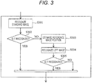
- FIG. 3 is a diagram illustrating a conventional exemplary process of recognizing the reference image after the standard image.
- the target is first recognized by the standard image.
- the appearance pattern information is present in the standard image, so that the target can be recognized (YES in S302).
- a predicted position when the target is shown in the reference image (IL) from the predicted disparity dp is estimated (S303).
- the position of the target in the reference image can be obtained as (IL(up + dp, vp)).
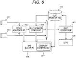
- FIG. 6 is a diagram illustrating an exemplary configuration of the image recognition system using the stereo camera in this embodiment.
- a pair of right and left images simultaneously captured by a pair of right and left image capture units 601 and 602 are input to a disparity measurement unit 603.
- the disparity measurement unit 603 calculates a disparity according to the input images, and generates the disparity image in which the disparity is expressed by shading.
- An object information estimation unit 604 estimates object information such as position, size, and distance of the target using the disparity image and the past object information registered in an object information table 606 described below.
- the past position of the target and a range occupied by the target on the image at that time are included.
- the predicted position (up, vp) and the predicted disparity dp are estimated.
- the size of the target to be estimated is a predicted range which is predicted to be occupied by the target on the image.
- an image selection unit 608 selects any one of the right and left images, and an object recognition unit 605 detects the object using the appearance pattern information and the estimated information in the object information estimation unit 604 in the selected image.
- the image selection unit 608 selects any one of the pair of images using the determination result of a concealment determination unit 607.
- the position information and the distance information detected by the object recognition unit 605 are stored in the object information table 606. Then, the recognition result of the object is output to an output unit 609.
- FIG. 7 is a flowchart illustrating an exemplary process of the object recognition based on the configuration of FIG. 6 .
- the initial detection indicates that the target is not detected in the past but new object is recognized in the frame for the first time.
- the information indicating whether the target is detected in the past is set to a detection flag (S704) and managed in the object information table 606.
- S704 detection flag
- the detection flag is set to ON and, if not, the detection flag is set to OFF. In the beginning, it is assumed that there is no information in the past.
- the right and left images are acquired (S702), and the disparity image is generated (S703).
- the detection flag is set to ON or OFF in order to determine whether there is the past information (S704). Since the detection flag at this time is OFF, the procedure moves to an initial detection flow.
- distance label information L and appearance information of the image are directly processed to perform the object information estimation process (S705).
- the standard image (the right image in this embodiment) in the pair of right and left images is selected as a detection target image (S706). This process corresponds to the process of the image selection unit 608 in FIG. 6 .
- the recognition process is performed in which the object is detected using the standard image (the detection target image) (S707).
- the object information of the target is registered in the object information table 606 (S709).
- the object information to be registered includes the information of the frame number, type/position/distance of the target with respect to the subject vehicle, and the size information of the target.
- the detection flag is changed to ON (S710).
- the detection flag is set to OFF (S713).
- the estimated size sxp indicates a size in the x direction of the target in the image
- the estimated size syp indicates a size in the y direction of the target in the image.
- the radius rp of the speed sign may be registered in the object information table 606.
- a concealment determination process is performed to determine whether there is another object at the predicted position (up, vp) of the target with respect to the subject vehicle so as to conceal the target (S715).
- the detailed content of the concealment determination process will be described below.
- one of the right and left images is determined as the detection target image from which the appearance pattern information is acquired (S716).
- the concealment determination process (S715) in a case where a visible image (an image in which the target is shown) is the standard image (the right image), the standard image is selected as the detection target image (S717).
- the visible image is the reference image (the left image)
- the reference image is selected as the detection target image (S718).
- the recognition process is not performed and the detection flag is set to OFF (S713).
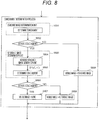
- FIG. 8 is a flowchart illustrating an exemplary process of the concealment determination process.
- the concealment determination unit 607 is divided into a standard image determination unit which determines the concealment with respect to the standard image (S801) and a reference image determination unit which determines the concealment with respect to the reference image (S803).
- the standard image determination unit obtains the current disparity information D (up, vp) from the predicted position (up, vp) predicted based on the detection information and the vehicle behavior information in the past, and determines whether the disparity in the peripheral position tends to be changed large compared to the predicted disparity dp.
- D up vp ⁇ dp > T 1
- T1 is a predetermined threshold.
- the peripheral position is set based on a predicted position of the target, a size of the target, and a predicted error.
- the peripheral position may be defined as a rectangular area having the left upper coordinates and the right lower coordinates as follows:
- the tendency of the disparity is determined based on excessiveness of the above condition in the rectangular area.
- the procedure moves to a reference image determination unit (S803).
- the visible image is output as the standard image.
- the disparity measurement unit In the stereo camera system, the disparity measurement unit generates the disparity image only based on any one of the images. Therefore, it cannot be confirmed whether the concealment occurs in the reference image. Therefore, a reverse standard disparity image D'(u',v') is generated in the reference image determination unit S803 (S804), and the concealment of the reference image is determined based on the reverse standard disparity image D' (u',v') (S805).
- the reverse standard disparity image D'(u',v') is generated by calculating a reverse standard disparity in which the left image of the reference image is changed into the standard image and the right image of the standard image is changed into the reference image.
- D' (up + dp, vp) is obtained using D' generated in the reverse standard disparity image generation unit S804, and it is determined whether the tendency of the disparity in the peripheral position is larger than the predicted disparity dp using the following (Equation 5).
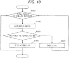
- FIGS. 9 and 10 While there are some methods of creating the reverse standard disparity image, the details of two types of reverse standard image generation units are illustrated in FIGS. 9 and 10 for example.
- FIG. 9 is a flowchart illustrating an example of a method of generating the reverse standard image
- FIG. 10 is a flowchart illustrating another example of a method of generating the reverse standard image.
- Such a reverse standard disparity image is locally generated with respect to the periphery of D' (up + dp, vp) which is obtained from the predicted position (up, vp) and the predicted disparity dp.
- a block is created from the right image generated by the disparity measurement unit and the disparity image Dr is generated based on the right image, and a block is created from the left image and the disparity image Dl is generated based on the left image.
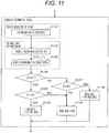
- FIG. 11 is another example of the concealment determination process.
- one of the pair of images, having a small concealment ratio of the target is selected.
- the concealment ratio indicates a degree that the object in front of the target blocks the target.
- the concealment ratio is determined by a ratio of pixels satisfying (Equation 4) and (Equation 5) within a range of the target.
- the concealment ratios can be expressed as follows (where, Cr is a concealment ratio in the standard image, and Cl is a concealment ratio in the reference image).
- Cr ⁇ U D up vp ⁇ dp ⁇ T / N
- Cl ⁇ U D ⁇ up ⁇ vp ⁇ ⁇ dp ⁇ T / N
- the function U in the above equation is a unit step function, and returns "1" when the content of the argument is equal to or more then "0" and returns "0" when the content is less than "0".
- "N" represents the number of pixels in an area of interest.
- the concealment ratio of the target in the standard image is calculated by the standard image determination unit (S1101)
- the concealment ratio of the target in the reference image is calculated by the reference image determination unit (S1103).
- the magnitude of the concealment ratios Cr and Cl is determined (S1104).
- the concealment ratio of the standard image is smaller than that of the reference image (Cr ⁇ Cl)
- the concealment ratio Cr is smaller than an appropriate threshold TC (Cr ⁇ TC) (YES in S1104 and YES in S1105)
- the concealment determination process sets the visible image as the standard image (S1106).
- the concealment determination process sets the visible image as the reference image (S1108). Then, in a case where the concealment ratio exceeds the threshold TC at any case, the output is made as no visible image (S1109).
- FIG. 12 is another example of the processing flow, and is a flowchart illustrating an exemplary process of the object recognition in a case where the reverse standard image is created for the first time.
- FIG. 13 is a flowchart illustrating an exemplary process of the concealment determination process in a case where the reverse standard image is created for the first time.
- the reverse standard disparity image is generated (S1204).
- a method of generating the reverse standard disparity image follows the flow of FIG. 9 or 10 but different in that the target area is the entire disparity image.
- the concealment determination process (S1216) at that time follows the flow illustrated in FIG. 13 .
- the concealment determination is performed based on a normal disparity image in S1301.
- the reverse standard disparity image is not generated unlike FIG. 8 , and the reverse standard disparity image generated in S1204 is used as it is.
- the reverse standard disparity image is generated at every time for the target. Therefore, when there are a lot of targets, the efficiency of the process illustrated in FIG. 12 may be reasonable.
- the recognition process is not performed on both image but only one image, so that a total processing time can be reduced.
Landscapes
- Engineering & Computer Science (AREA)
- Physics & Mathematics (AREA)
- Multimedia (AREA)
- General Physics & Mathematics (AREA)
- Theoretical Computer Science (AREA)
- Signal Processing (AREA)
- Computer Vision & Pattern Recognition (AREA)
- Electromagnetism (AREA)
- Radar, Positioning & Navigation (AREA)
- Remote Sensing (AREA)
- Health & Medical Sciences (AREA)
- Artificial Intelligence (AREA)
- Computing Systems (AREA)
- Databases & Information Systems (AREA)
- Evolutionary Computation (AREA)
- General Health & Medical Sciences (AREA)
- Medical Informatics (AREA)
- Software Systems (AREA)
- Image Analysis (AREA)
- Image Processing (AREA)
- Traffic Control Systems (AREA)
- Measurement Of Optical Distance (AREA)
- Closed-Circuit Television Systems (AREA)
Abstract
Description
- The present invention relates to a vehicle-mounted recognition device which recognizes an object through image processing.
- In recent years, a vehicle-mounted image recognition system is widely spread which recognizes surrounding vehicles and running lane through a vehicle-mounted camera to prevent an accident from happening. The recognition target objects are diversified, and besides the vehicle, a pedestrian and a road speed sign are included as the recognition target. As a solution, there is a technique of a stereo camera which measures a distance based on the principle of triangulation using two cameras. In the stereo camera, corresponding points of two cameras in a horizontal direction are obtained, and displacement therebetween is set as a disparity. A distance from the subject vehicle to the corresponding points is calculated based on the disparity and is held as a distance image. Then, since cameras are used in the stereo camera, besides the measurement of the distance by the disparity, for example, the object can be recognized using appearance pattern information itself captured by the camera.
-
PTL 1 discloses a technique of recognizing a sign using the stereo camera. In the technique ofPTL 1, an area of the sign is first estimated in the distance image, an approximate size of the sign is estimated from the distance, and then a template matching is performed according to the size so as to recognize the sign. -
PTL 2 discloses a vehicle-mounted image recognition system using a plurality of cameras (not limited to the stereo camera) in which, when the object of the detection target cannot be recognized due to a stain of a lens in one camera, a recognition process is performed by another camera to find out the object of the detection target. In the technique ofPTL 2, even when the object cannot be recognized in any one of images, the object can be found in the other image, so that detection missing can be prevented. -
- PTL 1:
Japanese Patent Application Laid-Open No. 2006-3994 - PTL 2: Publication of Patent No.
4,654,208 - However, in the method of recognizing the sign disclosed in
PTL 1, the sign is recognized only by one of two images. Therefore, in a case where the object is not shown in one image but found in the other image, the sign cannot be recognized. - In the case of the technique disclosed in
PTL 2, the detection missing can be prevented by recognizing both images. However, since the recognition process is respectively performed on the plurality of images, a lot of processing time is taken compared to the recognition process which is performed on only one image. In particular, in an embedded system of which calculation resources are tight, there is a request for reducing the processing time as short as possible. - The invention has been made in view of the above problems, and an object thereof is to provide a vehicle-mounted recognition device which can recognize a target in a short processing time.
- According to the invention in order to solve the above problems, there is provided a vehicle-mounted recognition device which recognizes a target from any one of a pair of images simultaneously captured by a pair of image capture units. The vehicle-mounted recognition device includes a disparity measurement unit which measures a disparity using the pair of images, an object information estimation unit which estimates a current position of the object from a past position of the object, a concealment determination unit which determines whether concealment of the target occurs in at least one of the pair of images based on a measurement result of the disparity measurement unit and an estimation result of the object information estimation unit, an image selection unit which selects an image, from which the target is recognizable, from the pair of images based on a determination result of the concealment determination unit, and an object recognition unit which recognizes the target using the selected image.
- According to the invention, even in a case where a target is captured only by one camera due to an object interposed with respect to the target, a recognition process is not performed on both image but only one image, so that a total processing time can be reduced. Further, objects, configurations, and features other than those described above will become clear through the explanation about the following embodiments.
-
- [
FIG. 1] FIG. 1 is a flowchart illustrating an exemplary process of an image recognition system using a stereo camera. - [
FIG. 2] FIG. 2 is a diagram for describing a specific example of disparity deduction. - [
FIG. 3] FIG. 3 is a diagram illustrating a conventional exemplary process of recognizing a reference image after a standard image. - [
FIG. 4] FIG. 4 is a diagram illustrating an exemplary image in which a sign becomes invisible in a right image. - [
FIG. 5] FIG. 5 is a diagram illustrating an exemplary image in which a sign becomes invisible in a left image. - [
FIG. 6] FIG. 6 is a diagram illustrating an exemplary configuration of the image recognition system using the stereo camera. - [
FIG. 7] FIG. 7 is a flowchart illustrating an exemplary process of object recognition. - [
FIG. 8] FIG. 8 is a flowchart illustrating an exemplary process of a concealment determination process. - [
FIG. 9] FIG. 9 is a flowchart illustrating an exemplary method of generating a reverse standard image. - [
FIG. 10] FIG. 10 is a flowchart illustrating another exemplary method of generating the reverse standard image. - [
FIG. 11] FIG. 11 is a flowchart illustrating an exemplary process of the concealment determination process based on a concealment ratio. - [
FIG. 12] FIG. 12 is a flowchart illustrating an exemplary process of the object recognition in a case where the reverse standard image is created for the first time. - [
FIG. 13] FIG. 13 is a flowchart illustrating an exemplary process of the concealment determination process in a case where the reverse standard image is created for the first time. - Hereinafter, embodiments of the invention will be described in detail with reference to the drawings.
FIG. 1 is a flowchart illustrating an exemplary process of an image recognition system using a stereo camera. - The stereo camera is mounted in a vehicle, and includes a pair of right and left image capture units (cameras) which capture the front side of the vehicle. In the stereo camera, a right image and a left image are respectively acquired by the pair of image capture units (S101, S102). Then, a distance up to an object captured by the principle of triangulation is measured based on a difference between appearance patterns in the right and left images. In order to measure a distance, when two image capture units capture the same object, a disparity which is an index indicating a separation degree of the object on two image coordinates of the right and left images is obtained, and a disparity image is generated (S103).
-
FIG. 2 is a diagram for describing a specific example of disparity deduction. First, any one of the right image and the left image is determined as an image serving as a standard, and the standard image is partitioned and divided into small rectangular block images. The image serving as a standard herein will be called as astandard image 201, and is set as a right image (IR(x, y)) in the following description if not otherwise specified. After thestandard image 201 is divided into the smallrectangular block images 202, an area matched with each rectangular block image is retrieved by a pixel length maxd in a horizontal direction (x direction) 203 from theother image 204. The other image thus retrieved is called areference image 204, and is set as a left image (IL(x, y)) in the following description if not otherwise specified. Further, (x, y) represents the image coordinates. When the coordinates from which the retrieving of a certain block starts in the left image is set to be equal to the coordinates of the right image from which the block is extracted, displacement in the retrieving from the coordinates is set as "d", and similarity indicating a matching rate between the blocks in the displacement d is set as S(x, y, d), a disparity Dr(u, v) is obtained as follows.
- Herein, argmax represents a function of outputting d (0 ≤ d < maxd) causing the largest S.
- In addition, a relation between the disparity image coordinates u, v and the coordinates x, y of the standard image is set as the following equation (where, sx and sy represent horizontal and vertical block sizes).

- The disparity Dr may be used as a disparity image D as it is, but herein the disparity image D is generated as described below.
- The reference image is partitioned into blocks, and the retrieving is made in the horizontal direction with respect to the standard image. In this case, the retrieving direction is set to a direction opposed to the
horizontal direction 203. Similarly to the disparity Dr, Dl is obtained, and the final disparity image is obtained using an appropriate threshold Td as follows.
else φ - This process is called a right and left image check. In other words, when the disparity image is generated, the block is created from the right image and the disparity image Dr is generated based on the right image, and the block is created from the left image and the disparity image Dl is generated based on the left image. Then, the disparity image D is generated by comparing the disparity image Dr with the disparity image Dl (a disparity image generation unit). This method is used for suppressing a mismatching. "φ" represents a state where the disparity is invalid. For example, in a case where an object is concealed by another object in front of the object in one image, it is not possible to obtain the disparity because there is no matched portion between the blocks at the time of the retrieving process. Besides the right and left image check, the determination of "φ" is performed based on the size of S (x, y, d) which is minimized at the time of matching.
- For example, assuming that the disparity of a detection target object is assigned with D(uo, vo), the distance (Z) up to the object can be obtained by the following equation using the disparity, a focal distance (f) of a lens of the image capture unit, a pixel interval (δ) of the capture element, and a baseline length (b) between the image capture units.

- After the disparity image D(u, v) is obtained, an object information estimation process is performed in which narrowing is performed to find out an object (target) of a detection target (S104). As a processing method, for example, (1) near areas having a similar disparity are collected and labeled, and the areas are considered as one object. It is expected that the same object is assigned with the same label. (2) The approximated position of the detection target object is narrowed down from appearance pattern information. (3) When there is recognition information of the last frame, the current position is estimated from behavior of the subject vehicle based on the recognition information.
- In the following description, a disparity label image in a case where the above (1) processing method is used is represented as L(u, v). Through the above processing method, object recognition for specifying an identity of the object is performed by analyzing the shape of the area assigned with the same label in L(u, v) with respect to the narrow-down area and the appearance pattern of the original standard image IR(x, y) (S105). Examples of the identity include a road sign, a pedestrian, a preceding vehicle, and the like. Further, appearance information at a position (u, v) can be obtained directly from (Equation 2). The result is transferred to a display or a control device (S106).
- Various objects are considered as the detection target object and, in this embodiment, the type of a road sign will be considered as a recognition target. For example, in the case of a speed sign, the pattern displayed in the sign is necessarily recognized as 30 km/h, 40 km/h, or the like.
-
FIG. 4 is a diagram illustrating an exemplary image in which the sign is invisible in the right image.FIG. 5 is a diagram illustrating an exemplary image in which the sign is invisible in the left image. -
FIG. 4 illustrates an example in which right and left images time-sequentially captured by the stereo camera are illustrated and anobject 403 of the detection target is concealed by anotherobject 402 in front thereof. The time-sequential images show an example in which the subject vehicle moves forward and the precedingvehicle 401 and thevehicle 402 on the right side also move forward in the same direction as the subject vehicle at a constant speed. Frame No. 1 to Frame No. 3 are sequentially captured in a predetermined time interval. - An object drawn with rectangular and circle on the right side in each image indicates an example of a
road sign 403. Theroad sign 403 is provided at the right end of aroad 404, and displayed in both right and left images in Frame No. 1. However, the road sign is concealed by the shadow of theother vehicle 402 which moves forward together with the subject vehicle in the right image of Frame No. 2, and thus a portion of theroad sign 403 becomes invisible. On the other hand, since the position of the left image capture unit is shifted and separated on the left side from the right image capture unit, theentire road sign 403 gets out of the shadow of the shadow of thevehicle 402 and is visible in the left image of Frame No. 2. Thesign 403 is concealed by the shadow of thevehicle 402 in the right image of Frame No. 3 and almost theentire sign 403 becomes invisible. On the other hand, the sign gets out of the shadow of thevehicle 402 and is visible in the left image of Frame No. 3. -
FIG. 5 illustrates an example in which the right and left of the invisible image is reversed to that ofFIG. 4 . Aroad sign 503 is provided at the left end of aroad 504, and theroad sign 503 is visible in the right and left images in Frame No. 1. However, thesign 503 is concealed by the shadow of avehicle 502 in the left image of Frame No. 3, and thus almost theentire sign 503 is invisible, and thesign 503 gets out of the shadow of thevehicle 502 and is visible in the right image of Frame No. 3. - For example, in the situations of Frame No. 2 and Frame No. 3 of
FIG. 4 or5 , the appearance pattern is different in the right and left images. Therefore, the disparity is not obtained (D(u, v) = φ), and it is not possible to narrow down the areas even simply using the label image generated based on the disparity image. In this case, the position and the distance in the current frame are predicted based on the past detection result and the vehicle behavior. - Specifically, when the vehicle behavior between the last frame and the current frame is expressed by ΔP on the world coordinate system based on a yaw rate sensor, a vehicle speed sensor, and information on the image, and the position of the sign recognized in the last frame is expressed by P(t-1), the position P(t) of the sign in the current frame can be expressed by P(t-1) + ΔP. The position of the detection object of the current frame in the image coordinate system can be predicted by converting the coordinates into the image coordinate system. The above example is not limited to the road sign, and may be applied to any object as long as the target is a stationary object.
- In a case where the target is a moving object, the position Q(t) of the moving object in the current frame can be expressed as Q(t-1) + ΔQ (where, ΔQ represents relative displacement of the subject vehicle with respect to the moving object between the frames, and Q(t-1) represents the position of the sign recognized in the last frame). In this way, the position predicted based on the past detection result and the vehicle behavior is denoted by a predicted position (up, vp). Further, the disparity in the current frame can also be predicted based on the predicted position in a depth direction, and the disparity is described below as a predicted disparity dp.
- When there is the predicted position, the areas can be narrowed down, so that the recognition process can be performed. A process flow of recognizing the sign in such a case is illustrated in
FIG. 3. FIG. 3 is a diagram illustrating a conventional exemplary process of recognizing the reference image after the standard image. - In the conventional example illustrated in
FIG. 3 , the target is first recognized by the standard image. Herein, as illustrated inFIG. 5 , when the target is concealed only in the reference image, the appearance pattern information is present in the standard image, so that the target can be recognized (YES in S302). - However, as illustrated in Frames No. 2 and 3 of
FIG. 4 , in a case where the target is concealed only in the standard image, there is no appearance pattern information, and thus the target cannot be recognized (NO in S302). - Therefore, in order to recognize the object in the reference image, first, a predicted position when the target is shown in the reference image (IL) from the predicted disparity dp is estimated (S303). The position of the target in the reference image can be obtained as (IL(up + dp, vp)). When the recognition process is performed in the reference image (the left image) using the appearance pattern information of the place, the target can be recognized even in such cases of Frames No. 2 and 3 of
FIG. 4 . In a case where the target is concealed in both right and left images (NO in S305), it is determined that the target cannot be recognized, and the recognition process is not performed. - In the case of the above-described conventional example, in the situations of Frames No. 2 and 3 of
FIG. 4 , there is a need to perform the recognition process twice in the standard image and the reference image. Therefore, there is a problem that it takes a processing time. It is desirable to shorten the processing time by suppressing the number of times of the recognition process. -
FIG. 6 is a diagram illustrating an exemplary configuration of the image recognition system using the stereo camera in this embodiment. First, a pair of right and left images simultaneously captured by a pair of right and leftimage capture units disparity measurement unit 603. Thedisparity measurement unit 603 calculates a disparity according to the input images, and generates the disparity image in which the disparity is expressed by shading. An objectinformation estimation unit 604 estimates object information such as position, size, and distance of the target using the disparity image and the past object information registered in an object information table 606 described below. In the past object information, the past position of the target and a range occupied by the target on the image at that time are included. Herein, the predicted position (up, vp) and the predicted disparity dp are estimated. In addition, the size of the target to be estimated is a predicted range which is predicted to be occupied by the target on the image. - Next, an
image selection unit 608 selects any one of the right and left images, and anobject recognition unit 605 detects the object using the appearance pattern information and the estimated information in the objectinformation estimation unit 604 in the selected image. Theimage selection unit 608 selects any one of the pair of images using the determination result of aconcealment determination unit 607. The position information and the distance information detected by theobject recognition unit 605 are stored in the object information table 606. Then, the recognition result of the object is output to anoutput unit 609. -
FIG. 7 is a flowchart illustrating an exemplary process of the object recognition based on the configuration ofFIG. 6 . First, the description will be made about a case where the target is initially detected in Frame No. 1. The initial detection indicates that the target is not detected in the past but new object is recognized in the frame for the first time. The information indicating whether the target is detected in the past is set to a detection flag (S704) and managed in the object information table 606. In general, there are a plurality of targets, but the description in this embodiment will be made about one object for the sake of simplicity in explanation. When there is a target, the detection flag is set to ON and, if not, the detection flag is set to OFF. In the beginning, it is assumed that there is no information in the past. - First, the right and left images are acquired (S702), and the disparity image is generated (S703). Next, it is determined whether the detection flag is set to ON or OFF in order to determine whether there is the past information (S704). Since the detection flag at this time is OFF, the procedure moves to an initial detection flow.
- In the initial detection flow, as described above, distance label information L and appearance information of the image are directly processed to perform the object information estimation process (S705). Then, the standard image (the right image in this embodiment) in the pair of right and left images is selected as a detection target image (S706). This process corresponds to the process of the
image selection unit 608 inFIG. 6 . - Next, the recognition process is performed in which the object is detected using the standard image (the detection target image) (S707). Herein, in a case where the target is detected from the standard image (YES in S708), the object information of the target is registered in the object information table 606 (S709). The object information to be registered includes the information of the frame number, type/position/distance of the target with respect to the subject vehicle, and the size information of the target. For example, in a case where the target is a road sign, the type/position/size/distance of the road sign are registered as the object information of Frame No. 1. At this time, the detection flag is changed to ON (S710). On the other hand, in a case where the target is not detected from the standard image (NO in S708), the detection flag is set to OFF (S713).
- Next, the description will be made about the case of Frame No. 2. Similarly to the case of Frame No. 1, the right and left images are acquired and the disparity is measured (S702, S703), and it is determined whether there is the past information (S704). In this process, since the detection flag is set to ON, the position/size/distance (disparity) of the object in the current frame is estimated from the past information in the object information estimation process (S714). Herein, in addition to the predicted position (up, vp) and the predicted disparity dp of the target described above, the estimated size (sxp, syp) is obtained. Herein, the estimated size sxp indicates a size in the x direction of the target in the image, and the estimated size syp indicates a size in the y direction of the target in the image. In a case where the target is circular like the speed sign (the case of a circle), the radius rp of the speed sign may be registered in the object information table 606.
- Next, a concealment determination process is performed to determine whether there is another object at the predicted position (up, vp) of the target with respect to the subject vehicle so as to conceal the target (S715). The detailed content of the concealment determination process will be described below. Based on the determination result of the concealment determination process (S715), one of the right and left images is determined as the detection target image from which the appearance pattern information is acquired (S716). For example, in the concealment determination process (S715), in a case where a visible image (an image in which the target is shown) is the standard image (the right image), the standard image is selected as the detection target image (S717). Then, in a case where the visible image is the reference image (the left image), the reference image is selected as the detection target image (S718). Then, in a case where it is determined in the concealment determination process (S715) that there is no visible image (that is, it is determined that the target is not shown in both of the standard image and the reference image), the recognition process is not performed and the detection flag is set to OFF (S713).
- Next, the detailed content of the concealment determination process in S715 will be described.
FIG. 8 is a flowchart illustrating an exemplary process of the concealment determination process. - The
concealment determination unit 607 is divided into a standard image determination unit which determines the concealment with respect to the standard image (S801) and a reference image determination unit which determines the concealment with respect to the reference image (S803). The standard image determination unit obtains the current disparity information D (up, vp) from the predicted position (up, vp) predicted based on the detection information and the vehicle behavior information in the past, and determines whether the disparity in the peripheral position tends to be changed large compared to the predicted disparity dp. As a criterion formula, the following (Equation 4) may be used.
- In the above (Equation 4), T1 is a predetermined threshold.
- Herein, in a case where the tendency of the disparity is larger than that of the predicted disparity dp (that is, the distance is shorter than predicted), it is determined that the target is concealed by the other object (that is, the concealment of the target occurs) (YES in S802). In a case where the tendency of the disparity is equal to or less than that of the predicted disparity dp, it is determined that the target is not concealed by the other object (that is, the concealment of the target does not occur) (NO in S802).
- Further, in a case where the tendency of the disparity at the peripheral position is D(up, vp) = φ (invalid disparity), it is determined that the concealment of the target does not occur. Herein, the peripheral position is set based on a predicted position of the target, a size of the target, and a predicted error. For example, when the predicted errors in the vertical and horizontal directions both are ±ep, the peripheral position may be defined as a rectangular area having the left upper coordinates and the right lower coordinates as follows:
- Left upper coordinates: (up - e, vp - e),
- Right lower coordinates: (up + sxp + e, vp + syp + e).
- The tendency of the disparity is determined based on excessiveness of the above condition in the rectangular area.
- In the standard image determination unit (S801), in a case where it is determined that the concealment occurs in the standard image (YES in S802), the procedure moves to a reference image determination unit (S803). In a case where it is determined that the concealment of the target does not occur in the standard image (NO in S802), the visible image is output as the standard image.
- In the stereo camera system, the disparity measurement unit generates the disparity image only based on any one of the images. Therefore, it cannot be confirmed whether the concealment occurs in the reference image. Therefore, a reverse standard disparity image D'(u',v') is generated in the reference image determination unit S803 (S804), and the concealment of the reference image is determined based on the reverse standard disparity image D' (u',v') (S805). The reverse standard disparity image D'(u',v') is generated by calculating a reverse standard disparity in which the left image of the reference image is changed into the standard image and the right image of the standard image is changed into the reference image.
- In the concealment determination of S805, D' (up + dp, vp) is obtained using D' generated in the reverse standard disparity image generation unit S804, and it is determined whether the tendency of the disparity in the peripheral position is larger than the predicted disparity dp using the following (Equation 5).

- In a case where the above (Equation 5) is established, it is determined that the concealment of the target occurs (YES in S806), and the output is made as no visible image (S807). On the other hand, in a case where (Equation 5) is not established, it is determined that the concealment of the target does not occur (NO in S806), and the visible image is output as the reference image (S808). The criterion formula at this time may be determined using an appropriate threshold T2 similarly to the standard image determination unit. The threshold T2 using in the above (Equation 5) is a predetermined threshold similarly to the standard image determination unit.
- While there are some methods of creating the reverse standard disparity image, the details of two types of reverse standard image generation units are illustrated in
FIGS. 9 and10 for example. -
FIG. 9 is a flowchart illustrating an example of a method of generating the reverse standard image, andFIG. 10 is a flowchart illustrating another example of a method of generating the reverse standard image. - First, in the example illustrated in
FIG. 9 , the reverse standard disparity image D'(u',v') is generated from the disparity image D(u, v). Even when any one of the right and left images is selected as the standard image, the distance up to the object is not changed, but only the position in each image of the object is changed in the horizontal direction. A correction amount in the horizontal direction is D(u, v) similarly to the disparity. In other words, the following equation is established.
- When D (u, v) = φ is satisfied, the object does not correspond to a conversion target. A plurality of values can be obtained for D(u', v') of the above equation. In that case, for example, a larger one of the values is selected as a disparity value.
- Such a reverse standard disparity image is locally generated with respect to the periphery of D' (up + dp, vp) which is obtained from the predicted position (up, vp) and the predicted disparity dp.
- Next, in the example illustrated in
FIG. 10 , a block is created from the right image generated by the disparity measurement unit and the disparity image Dr is generated based on the right image, and a block is created from the left image and the disparity image Dl is generated based on the left image. Then, the reverse standard image is created from the generated disparity images as follows.
else φ -
FIG. 11 is another example of the concealment determination process. In this example, one of the pair of images, having a small concealment ratio of the target, is selected. Herein, the concealment ratio indicates a degree that the object in front of the target blocks the target. For example, the concealment ratio is determined by a ratio of pixels satisfying (Equation 4) and (Equation 5) within a range of the target. In other words, the concealment ratios can be expressed as follows (where, Cr is a concealment ratio in the standard image, and Cl is a concealment ratio in the reference image).

- The function U in the above equation is a unit step function, and returns "1" when the content of the argument is equal to or more then "0" and returns "0" when the content is less than "0". "N" represents the number of pixels in an area of interest.
- Making an explanation using
FIG. 11 , the concealment ratio of the target in the standard image is calculated by the standard image determination unit (S1101), and the concealment ratio of the target in the reference image is calculated by the reference image determination unit (S1103). - Then, the magnitude of the concealment ratios Cr and Cl is determined (S1104). In a case where the concealment ratio of the standard image is smaller than that of the reference image (Cr < Cl), and the concealment ratio Cr is smaller than an appropriate threshold TC (Cr < TC) (YES in S1104 and YES in S1105), the concealment determination process sets the visible image as the standard image (S1106).
- On the other hand, in a case where the concealment ratio of the reference image is equal to or less than that of the standard image (Cr ≥ Cl) and the concealment ratio Cr is smaller than the appropriate threshold TC (Cr < TC) (NO in S1104 and YES in S1107) , the concealment determination process sets the visible image as the reference image (S1108). Then, in a case where the concealment ratio exceeds the threshold TC at any case, the output is made as no visible image (S1109).
-
FIG. 12 is another example of the processing flow, and is a flowchart illustrating an exemplary process of the object recognition in a case where the reverse standard image is created for the first time. Then,FIG. 13 is a flowchart illustrating an exemplary process of the concealment determination process in a case where the reverse standard image is created for the first time. - In the exemplary process illustrated in
FIG. 12 , after the disparity image is acquired (S1203), the reverse standard disparity image is generated (S1204). A method of generating the reverse standard disparity image follows the flow ofFIG. 9 or10 but different in that the target area is the entire disparity image. The concealment determination process (S1216) at that time follows the flow illustrated inFIG. 13 . The concealment determination is performed based on a normal disparity image in S1301. In S1303, the reverse standard disparity image is not generated unlikeFIG. 8 , and the reverse standard disparity image generated in S1204 is used as it is. InFIG. 8 , the reverse standard disparity image is generated at every time for the target. Therefore, when there are a lot of targets, the efficiency of the process illustrated inFIG. 12 may be reasonable. - According to the vehicle-mounted recognition device, even in a case where the target is shown only in one image due to the object interposed with respect to the target, the recognition process is not performed on both image but only one image, so that a total processing time can be reduced.
- Hitherto, while the embodiments of the invention have been described in detail, the invention is not limited to the embodiments, and various variations in design can be made within a scope not departing from the spirit of the invention described in claims. For example, the above embodiments have been described in detail in order to help with understanding of the invention, but there is no need to provide all the configurations. In addition, some configurations of a certain embodiment may be replaced with those of another embodiment, and the configurations of a certain embodiment may be added to another embodiment. Furthermore, additions, omissions, and substitutions may be made on some configurations of each embodiment using other configurations.
-
- 601
- image capture unit (left image capture unit)
- 602
- image capture unit (right image capture unit)
- 603
- disparity calculation unit
- 604
- object information estimation unit
- 605
- object recognition unit
- 606
- object information table
- 607
- concealment determination unit
- 608
- image selection unit
Claims (6)
- A vehicle-mounted recognition device which recognizes a target from any one of a pair of images simultaneously captured by a pair of image capture units, comprising:a disparity measurement unit which measures a disparity using the pair of images;an object information estimation unit which estimates a current position and a current range of the target as a predicted position and a predicted range from a past position and a past range of the target;a concealment determination unit which determines whether concealment of the target occurs in at least one of the pair of images based on a measurement result of the disparity measurement unit and an estimation result of the object information estimation unit;an image selection unit which selects a visible image, from which the target is recognizable, from the pair of images based on a determination result of the concealment determination unit; andan object recognition unit which recognizes the target using the selected visible image.
- The vehicle-mounted recognition device according to claim 1,
wherein the disparity measurement unit includes a disparity image generation unit which generates a disparity image by setting any one of the pair of images as a standard image and the other one as a reference image, and
wherein the concealment determination unit includes a reverse standard disparity image generation unit which generates a reverse standard disparity image by setting the predicted range of the other image as the standard image and the predicted range of the image as the reference image. - The vehicle-mounted recognition device according to claim 2,
wherein the reverse standard disparity image generation unit generates the reverse standard disparity image based on a disparity of the disparity image. - The vehicle-mounted recognition device according to claim 3,
wherein the object information estimation unit calculates a predicted disparity based on the predicted position, and
wherein the concealment determination unit includes
a standard image determination unit which compares the disparity of the disparity image with the predicted disparity to determine whether the concealment of the target occurs in the standard image, and
a reference image determination unit which, in a case where the standard image determination unit determines that the concealment of the target occurs, compares a disparity of the reverse standard disparity image with the predicted disparity to determine whether the concealment of the target occurs in the reference image. - The vehicle-mounted recognition device according to claim 4,
wherein, in a case where the standard image determination unit determines that the concealment of the target does not occur in the standard image,
the image selection unit selects the standard image as the visible image, and
wherein, in a case where the standard image determination unit determines that the concealment of the target occurs in the standard image and the reference image determination unit determines that the concealment of the target does not occur in the reference image,
the image selection unit selects the reference image as the visible image. - The vehicle-mounted recognition device according to claim 4,
wherein the standard image determination unit outputs a ratio, when the disparity of the disparity image is smaller than the predicted disparity in the predicted range, as a concealment ratio of the standard image,
wherein the reverse standard image determination unit calculates a ratio, when the disparity of the reverse standard disparity image is smaller than the predicted disparity in the predicted range, as a concealment ratio of the reverse standard image, and
wherein the concealment determination unit compares the concealment ratio of the standard image with the concealment ratio of the reverse standard image, and selects a small concealment ratio in the standard image and the reference image as the visible image.
Applications Claiming Priority (2)
| Application Number | Priority Date | Filing Date | Title |
|---|---|---|---|
| JP2014027791A JP6313063B2 (en) | 2014-02-17 | 2014-02-17 | In-vehicle recognition device |
| PCT/JP2015/050202 WO2015122212A1 (en) | 2014-02-17 | 2015-01-07 | Vehicle-mounted recognition device |
Publications (3)
| Publication Number | Publication Date |
|---|---|
| EP3109828A1 true EP3109828A1 (en) | 2016-12-28 |
| EP3109828A4 EP3109828A4 (en) | 2017-07-19 |
| EP3109828B1 EP3109828B1 (en) | 2024-04-24 |
Family
ID=53799960
Family Applications (1)
| Application Number | Title | Priority Date | Filing Date |
|---|---|---|---|
| EP15749369.3A Active EP3109828B1 (en) | 2014-02-17 | 2015-01-07 | Vehicle-mounted recognition device |
Country Status (4)
| Country | Link |
|---|---|
| US (1) | US10019635B2 (en) |
| EP (1) | EP3109828B1 (en) |
| JP (1) | JP6313063B2 (en) |
| WO (1) | WO2015122212A1 (en) |
Families Citing this family (4)
| Publication number | Priority date | Publication date | Assignee | Title |
|---|---|---|---|---|
| EP3136291A1 (en) * | 2015-08-31 | 2017-03-01 | Continental Automotive GmbH | Method and device for detecting objects in the dark by means of a vehicular camera and a vehicle lighting system |
| JP7291505B2 (en) * | 2019-03-19 | 2023-06-15 | 株式会社Subaru | External environment detection device |
| US11514594B2 (en) | 2019-10-30 | 2022-11-29 | Vergence Automation, Inc. | Composite imaging systems using a focal plane array with in-pixel analog storage elements |
| US12230649B2 (en) | 2020-05-19 | 2025-02-18 | Vergence Automation, Inc. | AI system on chip (SOC) for robotics vision applications |
Family Cites Families (12)
| Publication number | Priority date | Publication date | Assignee | Title |
|---|---|---|---|---|
| JPH08247775A (en) * | 1995-03-15 | 1996-09-27 | Toshiba Corp | Mobile body self-position identification device and self-position identification method |
| JP2002056377A (en) * | 2000-08-08 | 2002-02-20 | Alpine Electronics Inc | Image recognition device |
| US7003136B1 (en) * | 2002-04-26 | 2006-02-21 | Hewlett-Packard Development Company, L.P. | Plan-view projections of depth image data for object tracking |
| JP2006003994A (en) | 2004-06-15 | 2006-01-05 | Calsonic Kansei Corp | Road sign recognition device |
| JP4654208B2 (en) * | 2007-02-13 | 2011-03-16 | 日立オートモティブシステムズ株式会社 | Vehicle environment recognition device |
| JP4871909B2 (en) * | 2008-04-25 | 2012-02-08 | 日立オートモティブシステムズ株式会社 | Object recognition apparatus and object recognition method |
| EP2293588A1 (en) * | 2009-08-31 | 2011-03-09 | Robert Bosch GmbH | Method for using a stereovision camera arrangement |
| JP2013541915A (en) * | 2010-12-30 | 2013-11-14 | ワイズ オートモーティブ コーポレーション | Blind Spot Zone Display Device and Method |
| EP3869797B1 (en) * | 2012-08-21 | 2023-07-19 | Adeia Imaging LLC | Method for depth detection in images captured using array cameras |
| US9066085B2 (en) * | 2012-12-13 | 2015-06-23 | Delphi Technologies, Inc. | Stereoscopic camera object detection system and method of aligning the same |
| JP6550881B2 (en) * | 2014-07-14 | 2019-07-31 | 株式会社リコー | Three-dimensional object detection device, three-dimensional object detection method, three-dimensional object detection program, and mobile device control system |
| US9794543B2 (en) * | 2015-03-02 | 2017-10-17 | Ricoh Company, Ltd. | Information processing apparatus, image capturing apparatus, control system applicable to moveable apparatus, information processing method, and storage medium of program of method |
-
2014
- 2014-02-17 JP JP2014027791A patent/JP6313063B2/en active Active
-
2015
- 2015-01-07 WO PCT/JP2015/050202 patent/WO2015122212A1/en not_active Ceased
- 2015-01-07 EP EP15749369.3A patent/EP3109828B1/en active Active
- 2015-01-07 US US15/102,746 patent/US10019635B2/en active Active
Also Published As
| Publication number | Publication date |
|---|---|
| EP3109828B1 (en) | 2024-04-24 |
| JP2015153253A (en) | 2015-08-24 |
| US10019635B2 (en) | 2018-07-10 |
| WO2015122212A1 (en) | 2015-08-20 |
| JP6313063B2 (en) | 2018-04-18 |
| EP3109828A4 (en) | 2017-07-19 |
| US20160314364A1 (en) | 2016-10-27 |
Similar Documents
| Publication | Publication Date | Title |
|---|---|---|
| US10452931B2 (en) | Processing method for distinguishing a three dimensional object from a two dimensional object using a vehicular system | |
| US9659497B2 (en) | Lane departure warning system and lane departure warning method | |
| JP7675339B2 (en) | Object Tracking Device | |
| US8995714B2 (en) | Information creation device for estimating object position and information creation method and program for estimating object position | |
| EP3065087B1 (en) | Information processing apparatus, image capturing apparatus, control system applicable to moveable apparatus, information processing method, and carrier medium of program of method | |
| CN102194239B (en) | For the treatment of the method and system of view data | |
| EP1988505B1 (en) | Method and system for initializing templates of moving objects | |
| EP2696326A1 (en) | Object detection frame display device and object detection frame display method | |
| EP2858008A2 (en) | Target detecting method and system | |
| EP2557550A1 (en) | Vehicle periphery monitoring device, vehicle periphery monitoring method, and vehicle device | |
| EP3205084B1 (en) | Image processing method | |
| US10165246B2 (en) | Method and device for processing stereoscopic data | |
| CN103366155B (en) | Temporal coherence in unobstructed pathways detection | |
| JP2016148962A (en) | Object detection device | |
| US9747690B2 (en) | Image processing device, image processing method, and program | |
| KR20160088099A (en) | Method for determinating collision avoiding path of vehicle | |
| US7262710B2 (en) | Collision time estimation apparatus for vehicles, collision time estimation method for vehicles, collision alarm apparatus for vehicles, and collision alarm method for vehicles | |
| EP3109828B1 (en) | Vehicle-mounted recognition device | |
| EP2779024A1 (en) | Intersection recognizing apparatus and computer-readable storage medium | |
| KR102359083B1 (en) | Device for detecting moving object and method thereof | |
| Saleem et al. | Accuracy of free-space detection: monocular versus binocular vision | |
| JP2013069045A (en) | Image recognition device, image recognition method, and image recognition program | |
| JP2019191691A (en) | Image processing apparatus, mobile apparatus and method, and program | |
| EP3605015A1 (en) | Stereo image processing device | |
| JP5559121B2 (en) | Object type determination device |
Legal Events
| Date | Code | Title | Description |
|---|---|---|---|
| PUAI | Public reference made under article 153(3) epc to a published international application that has entered the european phase |
Free format text: ORIGINAL CODE: 0009012 |
|
| STAA | Information on the status of an ep patent application or granted ep patent |
Free format text: STATUS: REQUEST FOR EXAMINATION WAS MADE |
|
| 17P | Request for examination filed |
Effective date: 20160919 |
|
| AK | Designated contracting states |
Kind code of ref document: A1 Designated state(s): AL AT BE BG CH CY CZ DE DK EE ES FI FR GB GR HR HU IE IS IT LI LT LU LV MC MK MT NL NO PL PT RO RS SE SI SK SM TR |
|
| AX | Request for extension of the european patent |
Extension state: BA ME |
|
| DAX | Request for extension of the european patent (deleted) | ||
| A4 | Supplementary search report drawn up and despatched |
Effective date: 20170619 |
|
| RIC1 | Information provided on ipc code assigned before grant |
Ipc: H04N 7/18 20060101ALI20170612BHEP Ipc: G01C 3/06 20060101ALI20170612BHEP Ipc: G08G 1/09 20060101ALI20170612BHEP Ipc: H04N 13/02 20060101ALI20170612BHEP Ipc: B60R 1/00 20060101ALI20170612BHEP Ipc: H04N 13/00 20060101ALI20170612BHEP Ipc: G01C 21/26 20060101ALI20170612BHEP Ipc: G06K 9/00 20060101ALI20170612BHEP Ipc: G06T 7/60 20170101AFI20170612BHEP |
|
| STAA | Information on the status of an ep patent application or granted ep patent |
Free format text: STATUS: EXAMINATION IS IN PROGRESS |
|
| 17Q | First examination report despatched |
Effective date: 20200817 |
|
| RAP3 | Party data changed (applicant data changed or rights of an application transferred) |
Owner name: HITACHI ASTEMO, LTD. |
|
| REG | Reference to a national code |
Ref country code: DE Ref legal event code: R079 Free format text: PREVIOUS MAIN CLASS: G06T0007600000 Ipc: G06V0010250000 Ref country code: DE Ref legal event code: R079 Ref document number: 602015088431 Country of ref document: DE Free format text: PREVIOUS MAIN CLASS: G06T0007600000 Ipc: G06V0010250000 |
|
| GRAP | Despatch of communication of intention to grant a patent |
Free format text: ORIGINAL CODE: EPIDOSNIGR1 |
|
| STAA | Information on the status of an ep patent application or granted ep patent |
Free format text: STATUS: GRANT OF PATENT IS INTENDED |
|
| RIC1 | Information provided on ipc code assigned before grant |
Ipc: H04N 13/239 20180101ALI20231201BHEP Ipc: H04N 13/00 20060101ALI20231201BHEP Ipc: H04N 7/18 20060101ALI20231201BHEP Ipc: G01C 3/06 20060101ALI20231201BHEP Ipc: G06V 20/58 20220101ALI20231201BHEP Ipc: G06V 10/74 20220101ALI20231201BHEP Ipc: G06V 10/62 20220101ALI20231201BHEP Ipc: G06V 10/25 20220101AFI20231201BHEP |
|
| INTG | Intention to grant announced |
Effective date: 20231221 |
|
| GRAS | Grant fee paid |
Free format text: ORIGINAL CODE: EPIDOSNIGR3 |
|
| GRAA | (expected) grant |
Free format text: ORIGINAL CODE: 0009210 |
|
| STAA | Information on the status of an ep patent application or granted ep patent |
Free format text: STATUS: THE PATENT HAS BEEN GRANTED |
|
| AK | Designated contracting states |
Kind code of ref document: B1 Designated state(s): AL AT BE BG CH CY CZ DE DK EE ES FI FR GB GR HR HU IE IS IT LI LT LU LV MC MK MT NL NO PL PT RO RS SE SI SK SM TR |
|
| REG | Reference to a national code |
Ref country code: GB Ref legal event code: FG4D |
|
| REG | Reference to a national code |
Ref country code: CH Ref legal event code: EP |
|
| REG | Reference to a national code |
Ref country code: DE Ref legal event code: R096 Ref document number: 602015088431 Country of ref document: DE |
|
| REG | Reference to a national code |
Ref country code: IE Ref legal event code: FG4D |
|
| REG | Reference to a national code |
Ref country code: LT Ref legal event code: MG9D |
|
| REG | Reference to a national code |
Ref country code: NL Ref legal event code: MP Effective date: 20240424 |
|
| REG | Reference to a national code |
Ref country code: AT Ref legal event code: MK05 Ref document number: 1680454 Country of ref document: AT Kind code of ref document: T Effective date: 20240424 |
|
| PG25 | Lapsed in a contracting state [announced via postgrant information from national office to epo] |
Ref country code: NL Free format text: LAPSE BECAUSE OF FAILURE TO SUBMIT A TRANSLATION OF THE DESCRIPTION OR TO PAY THE FEE WITHIN THE PRESCRIBED TIME-LIMIT Effective date: 20240424 |
|
| PG25 | Lapsed in a contracting state [announced via postgrant information from national office to epo] |
Ref country code: NL Free format text: LAPSE BECAUSE OF FAILURE TO SUBMIT A TRANSLATION OF THE DESCRIPTION OR TO PAY THE FEE WITHIN THE PRESCRIBED TIME-LIMIT Effective date: 20240424 |
|
| PG25 | Lapsed in a contracting state [announced via postgrant information from national office to epo] |
Ref country code: IS Free format text: LAPSE BECAUSE OF FAILURE TO SUBMIT A TRANSLATION OF THE DESCRIPTION OR TO PAY THE FEE WITHIN THE PRESCRIBED TIME-LIMIT Effective date: 20240824 |
|
| PG25 | Lapsed in a contracting state [announced via postgrant information from national office to epo] |
Ref country code: BG Free format text: LAPSE BECAUSE OF FAILURE TO SUBMIT A TRANSLATION OF THE DESCRIPTION OR TO PAY THE FEE WITHIN THE PRESCRIBED TIME-LIMIT Effective date: 20240424 |
|
| PG25 | Lapsed in a contracting state [announced via postgrant information from national office to epo] |
Ref country code: HR Free format text: LAPSE BECAUSE OF FAILURE TO SUBMIT A TRANSLATION OF THE DESCRIPTION OR TO PAY THE FEE WITHIN THE PRESCRIBED TIME-LIMIT Effective date: 20240424 Ref country code: FI Free format text: LAPSE BECAUSE OF FAILURE TO SUBMIT A TRANSLATION OF THE DESCRIPTION OR TO PAY THE FEE WITHIN THE PRESCRIBED TIME-LIMIT Effective date: 20240424 |
|
| PG25 | Lapsed in a contracting state [announced via postgrant information from national office to epo] |
Ref country code: GR Free format text: LAPSE BECAUSE OF FAILURE TO SUBMIT A TRANSLATION OF THE DESCRIPTION OR TO PAY THE FEE WITHIN THE PRESCRIBED TIME-LIMIT Effective date: 20240725 |
|
| PG25 | Lapsed in a contracting state [announced via postgrant information from national office to epo] |
Ref country code: PT Free format text: LAPSE BECAUSE OF FAILURE TO SUBMIT A TRANSLATION OF THE DESCRIPTION OR TO PAY THE FEE WITHIN THE PRESCRIBED TIME-LIMIT Effective date: 20240826 |
|
| PG25 | Lapsed in a contracting state [announced via postgrant information from national office to epo] |
Ref country code: ES Free format text: LAPSE BECAUSE OF FAILURE TO SUBMIT A TRANSLATION OF THE DESCRIPTION OR TO PAY THE FEE WITHIN THE PRESCRIBED TIME-LIMIT Effective date: 20240424 |
|
| PG25 | Lapsed in a contracting state [announced via postgrant information from national office to epo] |
Ref country code: AT Free format text: LAPSE BECAUSE OF FAILURE TO SUBMIT A TRANSLATION OF THE DESCRIPTION OR TO PAY THE FEE WITHIN THE PRESCRIBED TIME-LIMIT Effective date: 20240424 |
|
| PG25 | Lapsed in a contracting state [announced via postgrant information from national office to epo] |
Ref country code: PL Free format text: LAPSE BECAUSE OF FAILURE TO SUBMIT A TRANSLATION OF THE DESCRIPTION OR TO PAY THE FEE WITHIN THE PRESCRIBED TIME-LIMIT Effective date: 20240424 |
|
| PG25 | Lapsed in a contracting state [announced via postgrant information from national office to epo] |
Ref country code: LV Free format text: LAPSE BECAUSE OF FAILURE TO SUBMIT A TRANSLATION OF THE DESCRIPTION OR TO PAY THE FEE WITHIN THE PRESCRIBED TIME-LIMIT Effective date: 20240424 |
|
| PG25 | Lapsed in a contracting state [announced via postgrant information from national office to epo] |
Ref country code: PT Free format text: LAPSE BECAUSE OF FAILURE TO SUBMIT A TRANSLATION OF THE DESCRIPTION OR TO PAY THE FEE WITHIN THE PRESCRIBED TIME-LIMIT Effective date: 20240826 Ref country code: PL Free format text: LAPSE BECAUSE OF FAILURE TO SUBMIT A TRANSLATION OF THE DESCRIPTION OR TO PAY THE FEE WITHIN THE PRESCRIBED TIME-LIMIT Effective date: 20240424 Ref country code: NO Free format text: LAPSE BECAUSE OF FAILURE TO SUBMIT A TRANSLATION OF THE DESCRIPTION OR TO PAY THE FEE WITHIN THE PRESCRIBED TIME-LIMIT Effective date: 20240724 Ref country code: LV Free format text: LAPSE BECAUSE OF FAILURE TO SUBMIT A TRANSLATION OF THE DESCRIPTION OR TO PAY THE FEE WITHIN THE PRESCRIBED TIME-LIMIT Effective date: 20240424 Ref country code: IS Free format text: LAPSE BECAUSE OF FAILURE TO SUBMIT A TRANSLATION OF THE DESCRIPTION OR TO PAY THE FEE WITHIN THE PRESCRIBED TIME-LIMIT Effective date: 20240824 Ref country code: HR Free format text: LAPSE BECAUSE OF FAILURE TO SUBMIT A TRANSLATION OF THE DESCRIPTION OR TO PAY THE FEE WITHIN THE PRESCRIBED TIME-LIMIT Effective date: 20240424 Ref country code: GR Free format text: LAPSE BECAUSE OF FAILURE TO SUBMIT A TRANSLATION OF THE DESCRIPTION OR TO PAY THE FEE WITHIN THE PRESCRIBED TIME-LIMIT Effective date: 20240725 Ref country code: FI Free format text: LAPSE BECAUSE OF FAILURE TO SUBMIT A TRANSLATION OF THE DESCRIPTION OR TO PAY THE FEE WITHIN THE PRESCRIBED TIME-LIMIT Effective date: 20240424 Ref country code: ES Free format text: LAPSE BECAUSE OF FAILURE TO SUBMIT A TRANSLATION OF THE DESCRIPTION OR TO PAY THE FEE WITHIN THE PRESCRIBED TIME-LIMIT Effective date: 20240424 Ref country code: BG Free format text: LAPSE BECAUSE OF FAILURE TO SUBMIT A TRANSLATION OF THE DESCRIPTION OR TO PAY THE FEE WITHIN THE PRESCRIBED TIME-LIMIT Effective date: 20240424 Ref country code: AT Free format text: LAPSE BECAUSE OF FAILURE TO SUBMIT A TRANSLATION OF THE DESCRIPTION OR TO PAY THE FEE WITHIN THE PRESCRIBED TIME-LIMIT Effective date: 20240424 Ref country code: RS Free format text: LAPSE BECAUSE OF FAILURE TO SUBMIT A TRANSLATION OF THE DESCRIPTION OR TO PAY THE FEE WITHIN THE PRESCRIBED TIME-LIMIT Effective date: 20240724 |
|
| PG25 | Lapsed in a contracting state [announced via postgrant information from national office to epo] |
Ref country code: DK Free format text: LAPSE BECAUSE OF FAILURE TO SUBMIT A TRANSLATION OF THE DESCRIPTION OR TO PAY THE FEE WITHIN THE PRESCRIBED TIME-LIMIT Effective date: 20240424 |
|
| PG25 | Lapsed in a contracting state [announced via postgrant information from national office to epo] |
Ref country code: EE Free format text: LAPSE BECAUSE OF FAILURE TO SUBMIT A TRANSLATION OF THE DESCRIPTION OR TO PAY THE FEE WITHIN THE PRESCRIBED TIME-LIMIT Effective date: 20240424 |
|
| PG25 | Lapsed in a contracting state [announced via postgrant information from national office to epo] |
Ref country code: CZ Free format text: LAPSE BECAUSE OF FAILURE TO SUBMIT A TRANSLATION OF THE DESCRIPTION OR TO PAY THE FEE WITHIN THE PRESCRIBED TIME-LIMIT Effective date: 20240424 |
|
| PG25 | Lapsed in a contracting state [announced via postgrant information from national office to epo] |
Ref country code: SK Free format text: LAPSE BECAUSE OF FAILURE TO SUBMIT A TRANSLATION OF THE DESCRIPTION OR TO PAY THE FEE WITHIN THE PRESCRIBED TIME-LIMIT Effective date: 20240424 Ref country code: RO Free format text: LAPSE BECAUSE OF FAILURE TO SUBMIT A TRANSLATION OF THE DESCRIPTION OR TO PAY THE FEE WITHIN THE PRESCRIBED TIME-LIMIT Effective date: 20240424 |
|
| REG | Reference to a national code |
Ref country code: DE Ref legal event code: R097 Ref document number: 602015088431 Country of ref document: DE |
|
| PG25 | Lapsed in a contracting state [announced via postgrant information from national office to epo] |
Ref country code: SM Free format text: LAPSE BECAUSE OF FAILURE TO SUBMIT A TRANSLATION OF THE DESCRIPTION OR TO PAY THE FEE WITHIN THE PRESCRIBED TIME-LIMIT Effective date: 20240424 |
|
| PG25 | Lapsed in a contracting state [announced via postgrant information from national office to epo] |
Ref country code: SM Free format text: LAPSE BECAUSE OF FAILURE TO SUBMIT A TRANSLATION OF THE DESCRIPTION OR TO PAY THE FEE WITHIN THE PRESCRIBED TIME-LIMIT Effective date: 20240424 Ref country code: SK Free format text: LAPSE BECAUSE OF FAILURE TO SUBMIT A TRANSLATION OF THE DESCRIPTION OR TO PAY THE FEE WITHIN THE PRESCRIBED TIME-LIMIT Effective date: 20240424 Ref country code: RO Free format text: LAPSE BECAUSE OF FAILURE TO SUBMIT A TRANSLATION OF THE DESCRIPTION OR TO PAY THE FEE WITHIN THE PRESCRIBED TIME-LIMIT Effective date: 20240424 Ref country code: EE Free format text: LAPSE BECAUSE OF FAILURE TO SUBMIT A TRANSLATION OF THE DESCRIPTION OR TO PAY THE FEE WITHIN THE PRESCRIBED TIME-LIMIT Effective date: 20240424 Ref country code: DK Free format text: LAPSE BECAUSE OF FAILURE TO SUBMIT A TRANSLATION OF THE DESCRIPTION OR TO PAY THE FEE WITHIN THE PRESCRIBED TIME-LIMIT Effective date: 20240424 Ref country code: CZ Free format text: LAPSE BECAUSE OF FAILURE TO SUBMIT A TRANSLATION OF THE DESCRIPTION OR TO PAY THE FEE WITHIN THE PRESCRIBED TIME-LIMIT Effective date: 20240424 |
|
| PLBE | No opposition filed within time limit |
Free format text: ORIGINAL CODE: 0009261 |
|
| STAA | Information on the status of an ep patent application or granted ep patent |
Free format text: STATUS: NO OPPOSITION FILED WITHIN TIME LIMIT |
|
| 26N | No opposition filed |
Effective date: 20250127 |
|
| PG25 | Lapsed in a contracting state [announced via postgrant information from national office to epo] |
Ref country code: SI Free format text: LAPSE BECAUSE OF FAILURE TO SUBMIT A TRANSLATION OF THE DESCRIPTION OR TO PAY THE FEE WITHIN THE PRESCRIBED TIME-LIMIT Effective date: 20240424 |
|
| REG | Reference to a national code |
Ref country code: CH Ref legal event code: PL |
|
| PG25 | Lapsed in a contracting state [announced via postgrant information from national office to epo] |
Ref country code: SE Free format text: LAPSE BECAUSE OF FAILURE TO SUBMIT A TRANSLATION OF THE DESCRIPTION OR TO PAY THE FEE WITHIN THE PRESCRIBED TIME-LIMIT Effective date: 20240424 |
|
| PG25 | Lapsed in a contracting state [announced via postgrant information from national office to epo] |
Ref country code: LU Free format text: LAPSE BECAUSE OF NON-PAYMENT OF DUE FEES Effective date: 20250107 Ref country code: MC Free format text: LAPSE BECAUSE OF FAILURE TO SUBMIT A TRANSLATION OF THE DESCRIPTION OR TO PAY THE FEE WITHIN THE PRESCRIBED TIME-LIMIT Effective date: 20240424 |
|
| GBPC | Gb: european patent ceased through non-payment of renewal fee |
Effective date: 20250107 |
|
| PG25 | Lapsed in a contracting state [announced via postgrant information from national office to epo] |
Ref country code: BE Free format text: LAPSE BECAUSE OF NON-PAYMENT OF DUE FEES Effective date: 20250131 Ref country code: GB Free format text: LAPSE BECAUSE OF NON-PAYMENT OF DUE FEES Effective date: 20250107 |
|
| PG25 | Lapsed in a contracting state [announced via postgrant information from national office to epo] |
Ref country code: FR Free format text: LAPSE BECAUSE OF NON-PAYMENT OF DUE FEES Effective date: 20250131 |
|
| PG25 | Lapsed in a contracting state [announced via postgrant information from national office to epo] |
Ref country code: CH Free format text: LAPSE BECAUSE OF NON-PAYMENT OF DUE FEES Effective date: 20250131 |
|
| REG | Reference to a national code |
Ref country code: BE Ref legal event code: MM Effective date: 20250131 |
|
| PG25 | Lapsed in a contracting state [announced via postgrant information from national office to epo] |
Ref country code: IE Free format text: LAPSE BECAUSE OF NON-PAYMENT OF DUE FEES Effective date: 20250107 |
|
| PG25 | Lapsed in a contracting state [announced via postgrant information from national office to epo] |
Ref country code: IT Free format text: LAPSE BECAUSE OF FAILURE TO SUBMIT A TRANSLATION OF THE DESCRIPTION OR TO PAY THE FEE WITHIN THE PRESCRIBED TIME-LIMIT Effective date: 20240424 |
|
| PGFP | Annual fee paid to national office [announced via postgrant information from national office to epo] |
Ref country code: DE Payment date: 20251203 Year of fee payment: 12 |
|
| PG25 | Lapsed in a contracting state [announced via postgrant information from national office to epo] |
Ref country code: CY Free format text: LAPSE BECAUSE OF FAILURE TO SUBMIT A TRANSLATION OF THE DESCRIPTION OR TO PAY THE FEE WITHIN THE PRESCRIBED TIME-LIMIT Effective date: 20240424 |
|
| PG25 | Lapsed in a contracting state [announced via postgrant information from national office to epo] |
Ref country code: TR Free format text: LAPSE BECAUSE OF FAILURE TO SUBMIT A TRANSLATION OF THE DESCRIPTION OR TO PAY THE FEE WITHIN THE PRESCRIBED TIME-LIMIT Effective date: 20240424 |
|
| PG25 | Lapsed in a contracting state [announced via postgrant information from national office to epo] |
Ref country code: LT Free format text: LAPSE BECAUSE OF FAILURE TO SUBMIT A TRANSLATION OF THE DESCRIPTION OR TO PAY THE FEE WITHIN THE PRESCRIBED TIME-LIMIT Effective date: 20240424 |