EP3109821A1 - Real-time light-field denoising - Google Patents
Real-time light-field denoising Download PDFInfo
- Publication number
- EP3109821A1 EP3109821A1 EP15306015.7A EP15306015A EP3109821A1 EP 3109821 A1 EP3109821 A1 EP 3109821A1 EP 15306015 A EP15306015 A EP 15306015A EP 3109821 A1 EP3109821 A1 EP 3109821A1
- Authority
- EP
- European Patent Office
- Prior art keywords
- reference pixel
- value
- light
- views
- pixel
- Prior art date
- Legal status (The legal status is an assumption and is not a legal conclusion. Google has not performed a legal analysis and makes no representation as to the accuracy of the status listed.)
- Withdrawn
Links
Images

Classifications
-
- G—PHYSICS
- G06—COMPUTING OR CALCULATING; COUNTING
- G06T—IMAGE DATA PROCESSING OR GENERATION, IN GENERAL
- G06T5/00—Image enhancement or restoration
- G06T5/70—Denoising; Smoothing
-
- G—PHYSICS
- G06—COMPUTING OR CALCULATING; COUNTING
- G06T—IMAGE DATA PROCESSING OR GENERATION, IN GENERAL
- G06T2207/00—Indexing scheme for image analysis or image enhancement
- G06T2207/10—Image acquisition modality
- G06T2207/10052—Images from lightfield camera
Definitions
- the field of the invention relates to light-field imaging. More particularly, the invention pertains to technologies for processing light-field data.
- aspects of the invention relate to a method for denoising in real-time light data acquired with a plenoptic camera.
- Conventional image capture devices render a three-dimensional scene onto a two-dimensional sensor.
- a conventional capture device captures a two-dimensional (2-D) image representing an amount of light that reaches each point on a photo-sensor (or photo-detector) within the device.
- this 2-D image contains no information about the directional distribution of the light rays that reach the photo-sensor (may be referred to as the light-field). Depth, for example, is lost during the acquisition.
- a conventional capture device does not store most of the information about the light distribution from the scene.
- Light-field capture devices (also referred to as “light-field data acquisition devices”) have been designed to measure a four-dimensional (4D) light-field of the scene by capturing the light from different viewpoints of that scene. Thus, by measuring the amount of light traveling along each beam of light that intersects the photo-sensor, these devices can capture additional optical information (information about the directional distribution of the bundle of light rays) for providing new imaging applications by post-processing.
- the information acquired/obtained by a light-field capture device is referred to as the light-field data.
- Light-field capture devices are defined herein as any devices that are capable of capturing light-field data.
- Light-field data processing comprises notably, but is not limited to, generating refocused images of a scene, generating perspective views of a scene, generating depth maps of a scene, generating extended depth of field (EDOF) images, generating stereoscopic images, and/or any combination of these.
- EEOF extended depth of field
- a first group of light-field capture device also referred to as "camera array” embodies an array of cameras that image onto a single shared image sensor or different image sensors. These devices require therefore an extremely accurate arrangement and orientation of cameras, which make their manufacturing often complex and costly.
- a second group of light-field capture device also referred to as “plenoptic device” or “plenoptic camera” embodies a micro-lens array positioned in the image focal field of the main lens, and before a photo-sensor on which one micro-image per micro-lens is projected.
- Plenoptic cameras are divided in two types depending on the distance between the micro-lens array and the photo-sensor. Regarding the “type 1 plenoptic cameras”, this distance is equal to the micro-lenses focal length (as presented in the article " Light-field photography with a hand-held plenoptic camera” by R. Ng et al., CSTR, 2(11), 2005 ).
- each microimage depicts a certain area of the captured scene and each pixel of this microimage depicts this certain area from the point of view of a certain sub-aperture location on the main lens exit pupil.
- adjacent microimages may partially overlap. One pixel located within such overlaying portions may therefore capture light rays refracted at different sub-aperture locations on the main lens exit pupil.
- the raw image of the scene obtained as a result is the sum of all the pixels of the photo-sensor belonging to one microimage and/or another.
- the angular information of the light-field is then given by the relative position of pixels in the microimages with respect to the center of these microimages.
- demultiplexing Based on this raw image, the extraction of an image of the captured scene from a certain point of view, also called “demultiplexing” in the following description, can be performed.
- demultiplexing step consists in reorganizing the pixels of this raw image in such a way that all pixels capturing the scene with a certain angle of incidence are stored in a same pixel grid (also commonly called “view” or “sub-aperture view” in the scientist language).
- this process also involves stitching the overlapping portions of the microimages and not only reorganizing pixels, as presented in the article " Generating EPI Representations of 4D Light Fields with a Single Lens Focused Plenoptic Camera", Wanner et al., ISCV 2011 ).
- the demultiplexing process can also be seen as a data conversion from the 2D raw image to the 4D light-field.
- the resulting demultiplexed light-field data can be represented by a matrix of views in which all the views are horizontally and vertically aligned.
- documents of the background art disclose a processing method performed on an input image before demultiplexing, which consists in averaging the value of a pixel group that depicts the same region of an object space.
- This method has several drawbacks. First, it induces a pre-processing step performed on the input image before demultiplexing. This additional step involves a significant increase of the corresponding computing load. In addition, this method cannot be implemented on a light-field data that has already been demultiplexed. Furthermore, this method involves an indistinct and irreversible reduction of the light-field workable data.
- references in the specification to "one embodiment”, “an embodiment”, “an example embodiment”, indicate that the embodiment described may include a particular feature, structure, or characteristic, but every embodiment may not necessarily include the particular feature, structure, or characteristic. Moreover, such phrases are not necessarily referring to the same embodiment. Further, when a particular feature, structure, or characteristic is described in connection with an embodiment, it is submitted that it is within the knowledge of one skilled in the art to affect such feature, structure, or characteristic in connection with other embodiments whether or not explicitly described.
- a method for determining the value of at least one reference pixel is disclosed, the reference pixel being part of a reference view of a matrix of views obtained from a given demultiplexed light-field data acquired with a plenoptic device.
- This method comprises calculating the value of the reference pixel by averaging the respective weighted values of a plurality of corresponding pixels, the reference pixel and the corresponding pixels depicting a same area of a scene captured while belonging to different views of the matrix of views.
- the expression "light-field data acquired with a plenoptic device” is also referred to under the terms “plenoptic image”.
- the expression “demultiplexed light-field data acquired with a plenoptic device” refers to the raw image of a scene acquired with a plenoptic device, whose pixels have been demultiplexed. Such demultiplexed light-field data are usually represented by a matrix of views in which all the views are horizontally and vertically aligned and depict the same scene with different angles of incidence.
- the expression “reference view” refers to a particular view of the matrix that comprises at least one pixel, referred to as "a reference pixel", whose value shall be determined.
- a method according to embodiments of the invention relies on a new and inventive approach of plenoptic image processing, which takes benefit on the specific layout of demultiplexed plenoptic images, and more precisely on the invariability of the disparity, in order to implement a method for determining the value of a pixel, which features a low computational load, while preserving the workable data of the light field.
- Another advantage of such a method is that it is adapted to denoise the value of at least one reference pixel of a demultiplexed plenoptic image.
- Another advantage of such a method is that it is adapted to be implemented on any demultiplexed plenoptic image.
- the demultiplexed plenoptic image is not displayed. Nevertheless, on an analytical point of view, the position of each corresponding pixel can be defined as a particular solution of the application of a disparity function of the light-field data on the position of the reference pixel.
- a method for determining the value of at least one reference pixel of a demultiplexed plenoptic image wherein the value of the reference pixel is equal to a weighted average of the respective values of a plurality of corresponding pixels, the coordinates of each corresponding pixel being a solution of the application of a disparity function of the light-field data on the coordinates of the reference pixel.
- the step of calculating implements a variable weight for each of the plurality of corresponding pixels.
- One advantage of this technical feature is the ability to adapt the weight, and therefore the method for determining the reference pixel value, according to specific parameters, including but not limited to the related value of the corresponding pixel compared with the reference pixel, the position of the reference pixel on the captured scene, and a modulation parameter pre-set by an operator.
- the method comprises a prior step of detecting discontinuities on the light-field data.
- This technical feature allows adapting the method for determining the reference pixel value according to the level of discontinuity detected in the reference pixel neighbourhood.
- this prior-step of detection is implemented by an edge detector, as described in the article entitled "A Computational Approach to
- the value of the variable weight is either:
- a threshold value above which the level of discontinuity is considered as high is pre-set by an operator.
- the risk of artifacts creation increases with the level of discontinuity, for example when the position of the reference pixel is getting closer to an image border. It is then beneficial to level up the accuracy of the weight in order to limit the creation of artifacts. On the other hand, such an increase of the weight accuracy also involves an increase of the computational load.
- the adaptation of the weight setting depending on the outcome of the discontinuities detection, has the double advantage to prevent the creation of artifacts at the edges of the captured image, while limiting the computational burden of the calculation process.
- I( x,y ) I'( x i ,y i) is the variation in pixel value between the reference pixel (x,y) and the corresponding pixel (x i ,y i ), and
- h is a variable modulation parameter
- variable weight is determined using a tabulated version of the exponential function.
- the method comprises setting the disparity function.
- a method allows determining in an autonomous way the disparity function of a demultiplexed plenoptic image, in order to determine the positions of the corresponding pixels, based on the position of the reference pixel.
- setting the disparity function is performed as described in ECCV 2014, "Accurate Disparity Estimation for Plenoptic Images" by N. Sabater, V. Drazic, M. Seifi, G. Sandri and P. Perez .
- setting the disparity function depends on the outcome of detecting discontinuities.
- This technical feature has the double advantage to allow setting a satisfactory disparity function, while limiting the computational burden of the calculation process.
- the value of the reference pixel depicts the value of a group of pixels surrounding the reference pixel
- the value of the at least one corresponding pixel depicts the value of a group of pixels surrounding the at least one corresponding pixel
- the light field data is of a video type.
- an apparatus for determining the value of at least one reference pixel the reference pixel being part of a reference view of a matrix of views obtained from a given demultiplexed light-field data acquired with a plenoptic device.
- Such an apparatus comprises a module for computing the respective weighted values of a plurality of corresponding pixels, the reference pixel and the corresponding pixels depicting a same area of a scene captured while belonging to different views of the matrix of views, in order to determine the value of the reference pixel.
- the apparatus embodies at least one sensor adapted to detect discontinuities on the light-field data.
- the present disclosure pertains a computer program product downloadable from a communication network and/or recorded on a medium readable by a computer and/or executable by a processor.
- a computer program product comprises program code instructions for implementing the method.
- the present disclosure pertains a non-transitory computer-readable carrier medium comprising a computer program product recorded thereon and capable of being run by a processor, including program code instructions for implementing the method.
- the present disclosure relates to methods for determining the processed value of at least one pixel of a matrix of views resulting from the demultiplexing of a light-field data acquired from a plenoptic camera.
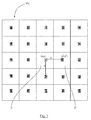
- Figure 1 illustrates a matrix of views M v , in this case, 5*5 views, obtained from a demultiplexed plenoptic image. Each of these views depicts a same captured scene, but from different point of views, corresponding to different sub-apertures of the plenoptic camera main lens. All the views are vertically and horizontally aligned.
- the central view is randomly designated as a reference view V, comprising a reference pixel of coordinates (x, y) whose value I(x, y) is intended to be denoised.
- the different pixels are referred to through their coordinates on the matrix of views M v .
- the reference pixel is referred to as (x, y).
- the reference view V is surrounded by corresponding views V i comprising for each of them one corresponding pixel (x i , y i ) whose value is I i (x i , y i ), with i being the view index.
- the shift d between corresponding pixels (x i , y i ) of two consecutive horizontal or vertical views V i also referred to under the terms "parallax” or "disparity", remain constant through the views.
- the demultiplexed plenoptic image is not displayed under the form of a matrix of corresponding views. Nevertheless, on an analytical point of view, the position of each corresponding pixel (x i , y i ) can therefore be defined as a particular solution of the application of a disparity function D(x, y) of the light-field data on the position of the reference pixel (x, y).
- Non-Local means processing method specific to demultiplexed plenoptic images, which consists in replacing the heavy loading algorithms of corresponding pixels mapping of background art by such a non-complex and invariable disparity function.
- Figure 2 illustrates in more details the successive steps implemented by a method for denoising a demultiplexed plenoptic image according to one embodiment of the disclosure.
- step INPUT 2 After an initialization step INIT 1, both a demultiplexed plenoptic image DmX_Img and the coordinates (x, y) of a reference pixel to be processed are inputted (step INPUT 2).
- step INPUT 2 may be conducted either automatically or by an operator.
- step DETECT 3 the level of discontinuities at the position of the reference pixel (x, y) is measured, for example by implementing an edge detector, as described in the article entitled " A Computational Approach to Edge Detection” by John Canny .
- edge detector as described in the article entitled " A Computational Approach to Edge Detection” by John Canny .
- the method for denoising may be implemented without running the step DETECT 3, therefore reducing on the one hand the corresponding computing load, while increasing on the other hand the risk of artifacts creation at the edges of the captured image.
- the disparity function D(x, y) is determined, depending on the outcome of the step DETECT 3. If the reference pixel (x, y) is not positioned at one edge of the captured image, the disparity estimation does not need to be very accurate, an integer accuracy being for example sufficient, and can therefore be performed by running a fast disparity estimation method, as the one presented in " A precise real-time stereo algorithm" by Neus Sabater, Valter Drazic, Proceedings of the 27th Conference on Image and Vision Computing New Zealand, ACM, 2012 .
- the reference pixel (x, y) is positioned at one edge of the image, as detected following the step DETECT 3, a more accurate disparity estimation can be performed, as described in ECCV2014, "Accurate Disparity Estimation for Plenoptic Images" by N. Sabater, V. Drazic, M. Seifi, G. Sandri and P. Perez .
- the step SETTING D(x, y) 4 could be run by conducting either a fast or a more accurate disparity estimation, depending on the assumption made on the position of the reference pixel (x, y) regarding the edges of the captured image.
- step SETTING W((x, y), (x i , y')) 5 the weight W between the reference pixel (x, y) and the corresponding pixel (x i , y i ) is determined depending on the outcome of the step DETECT 3. If the reference pixel (x, y) is not positioned at one edge of the captured image, we know by construction that the values I(x, y) and I i (x i , y i ) are similar. It is therefore reasonable to set a value of weight W equal to 1.
- the computation of the weight W regarding the formulation of Buades can be performed in an efficient way using a tabulated version of the exponential function.
- the step SETTING W((x, y), (x i , y i )) 5 could be run by choosing a weight value W equal either to 1, or to the formulation of Buades mentioned above, depending on the assumption made on the position of the reference pixel (x, y) regarding the edges of the captured image.
- ⁇ xy is the set of corresponding pixel positions (x i , y i ) in the other views V i of the matrix of views M v
- C ⁇ ( x i ,y i ) ⁇ ⁇ xy W (( x, y ),( x i , y i )) is the normalization factor.
- the present method for denoising the value of one reference pixel (x, y) is repeated for each pixel of the reference view V, in order to obtain a denoised demultiplexed plenoptic image.
- the present method is implemented for determining the value of a patch B (x, y) centered at the reference pixel (x, y) based on the respective values of patches B i (xi, yi) centered on the corresponding pixels (x i , y i ).
- the value I(x, y) of the reference pixel (x, y) depicts the value of a group B (x, y) of pixels surrounding the reference pixel (x, y), and the value I i (x i , y i ) of the reference pixel (x i , y i ) depicts the value of a group B i (xi, yi) of pixels surrounding the corresponding pixel (x i , y i ).
- the value of the patch B( x, y) is calculated by averaging the respective values of the pixels included in said patch B( x, y) .
- One of the main advantages of the present method is that it can be implemented on any demultiplexed plenoptic image, while limiting significantly the computing load of the corresponding process, and enabling the preservation of the workable data of the light field.
- Figure 3 is a schematic block diagram illustrating an example of an apparatus for determining the denoised value ⁇ (x, y) of at least one reference pixel (x, y) obtained from a given demultiplexed plenoptic image DmX-Img, in a way which limits significantly the computing load of the corresponding process, according to an embodiment of the present disclosure.
- An apparatus 7 illustrated in Figure 3 includes a processor 9, a storage unit 10, an interface unit 11 and a sensor 8, which are connected by a bus 12.
- a processor 9 a storage unit 10
- an interface unit 11 an interface unit 11
- a sensor 8 which are connected by a bus 12.
- constituent elements of the computer apparatus 7 may be connected by a connection other than a bus connection using the bus 12.
- the processor 9 controls operations of the apparatus 7.
- the storage unit 10 stores at least one program to be executed by the processor 9, and various data, including data of plenoptic images, parameters used by computations performed by the processor 9, intermediate data of computations performed by the processor 9, and so on.
- the storage unit 10 may notably store the value and the coordinates of a reference pixel (x, y), as provided by a plenoptic device.
- the processor 9 may be formed by any known and suitable hardware, or software, or by a combination of hardware and software.
- the processor 9 may be formed by dedicated hardware such as a processing circuit, or by a programmable processing unit such as a CPU (Central Processing Unit) that executes a program stored in a memory thereof.
- CPU Central Processing Unit
- the storage unit 10 may be formed by any suitable storage or means capable of storing the program, data, or the like in a computer-readable manner.
- Examples of the storage unit 10 include non-transitory computer-readable storage media such as semiconductor memory devices, and magnetic, optical, or magneto-optical recording media loaded into a read and write unit.
- the program causes the processor 9 to perform a process for determining the denoised value ⁇ (x, y) of at least one reference pixel (x, y) obtained from a given plenoptic image DmX-Img, by computing the respective weighted values I i (x i , y') of a plurality of corresponding pixels (x i , y i ) according to an embodiment of the present disclosure as described above with reference to Figure 2 .
- the interface unit 11 provides an interface between the apparatus 7 and an external apparatus.
- the interface unit 11 may be in communication with the external apparatus via cable or wireless communication.
- the external apparatus may be a plenoptic camera.
- plenoptic images can be input from the plenoptic camera to the apparatus 7 through the interface unit 11, and then stored in the storage unit 10.
- the apparatus 7 and the plenoptic camera may communicate with each other via cable or wireless communication.
- processor 9 may comprise different modules and units embodying the functions carried out by the apparatus 7 according to embodiments of the present disclosure, such as:
- modules may also be embodied in several processors 9 communicating and co-operating with each other.
- aspects of the present principles can be embodied as a system, method or computer readable medium. Accordingly, aspects of the present principles can take the form of an entirely hardware embodiment, an entirely software embodiment (including firmware, resident software, micro-code, and so forth), or an embodiment combining software and hardware aspects.
- a hardware component comprises a processor that is an integrated circuit such as a central processing unit, and/or a microprocessor, and/or an Application-specific integrated circuit (ASIC), and/or an Application-specific instruction-set processor (ASIP), and/or a graphics processing unit (GPU), and/or a physics processing unit (PPU), and/or a digital signal processor (DSP), and/or an image processor, and/or a coprocessor, and/or a floating-point unit, and/or a network processor, and/or an audio processor, and/or a multi-core processor.
- ASIC Application-specific integrated circuit
- ASIP Application-specific instruction-set processor
- GPU graphics processing unit
- PPU physics processing unit
- DSP digital signal processor
- image processor and/or a coprocessor, and/or a floating-point unit, and/or a network processor, and/or an audio processor, and/or a multi-core processor.
- the hardware component can also comprise a baseband processor (comprising for example memory units, and a firmware) and/or radio electronic circuits (that can comprise antennas), which receive or transmit radio signals.
- the hardware component is compliant with one or more standards such as ISO/IEC 18092 / ECMA-340, ISO/IEC 21481 / ECMA-352, GSMA, StoLPaN, ETSI / SCP (Smart Card Platform), GlobalPlatform (i.e. a secure element).
- the hardware component is a Radio-frequency identification (RFID) tag.
- a hardware component comprises circuits that enable Bluetooth communications, and/or Wi-fi communications, and/or Zigbee communications, and/or USB communications and/or Firewire communications and/or NFC (for Near Field) communications.
- aspects of the present principles can take the form of a computer readable storage medium. Any combination of one or more computer readable storage medium(s) may be utilized.
Landscapes
- Physics & Mathematics (AREA)
- General Physics & Mathematics (AREA)
- Engineering & Computer Science (AREA)
- Theoretical Computer Science (AREA)
- Studio Devices (AREA)
- Image Processing (AREA)
Abstract
Method for determining the value Φ(x, y) of at least one reference pixel (x, y), the reference pixel (x, y) being part of a reference view V of a matrix of views Mv obtained from a given demultiplexed light-field data DmX_Img acquired with a plenoptic device, wherein the method comprises calculating 6 the value Φ(x, y) by averaging the respective weighted values li(xi, y') of a plurality of corresponding pixels (xi, yi), the reference pixel (x, y) and the corresponding pixels (xi, yi) depicting a same area of a scene captured while belonging to different views (V, Vi) of the matrix of views Mv.
Description
- The field of the invention relates to light-field imaging. More particularly, the invention pertains to technologies for processing light-field data.
- Aspects of the invention relate to a method for denoising in real-time light data acquired with a plenoptic camera.
- This section is intended to introduce the reader to various aspects of art, which may be related to various aspects of the present disclosure that are described and/or claimed below. This discussion is believed to be helpful in providing the reader with background information to facilitate a better understanding of the various aspects of the present disclosure. Accordingly, it should be understood that these statements are to be read in this light, and not as admissions of prior art.
- Conventional image capture devices render a three-dimensional scene onto a two-dimensional sensor. During operation, a conventional capture device captures a two-dimensional (2-D) image representing an amount of light that reaches each point on a photo-sensor (or photo-detector) within the device. However, this 2-D image contains no information about the directional distribution of the light rays that reach the photo-sensor (may be referred to as the light-field). Depth, for example, is lost during the acquisition. Thus, a conventional capture device does not store most of the information about the light distribution from the scene.
- Light-field capture devices (also referred to as "light-field data acquisition devices") have been designed to measure a four-dimensional (4D) light-field of the scene by capturing the light from different viewpoints of that scene. Thus, by measuring the amount of light traveling along each beam of light that intersects the photo-sensor, these devices can capture additional optical information (information about the directional distribution of the bundle of light rays) for providing new imaging applications by post-processing. The information acquired/obtained by a light-field capture device is referred to as the light-field data. Light-field capture devices are defined herein as any devices that are capable of capturing light-field data.
- Light-field data processing comprises notably, but is not limited to, generating refocused images of a scene, generating perspective views of a scene, generating depth maps of a scene, generating extended depth of field (EDOF) images, generating stereoscopic images, and/or any combination of these.
- There are several groups of light-field capture device.
- A first group of light-field capture device, also referred to as "camera array", embodies an array of cameras that image onto a single shared image sensor or different image sensors. These devices require therefore an extremely accurate arrangement and orientation of cameras, which make their manufacturing often complex and costly.
- A second group of light-field capture device, also referred to as "plenoptic device" or "plenoptic camera", embodies a micro-lens array positioned in the image focal field of the main lens, and before a photo-sensor on which one micro-image per micro-lens is projected. Plenoptic cameras are divided in two types depending on the distance between the micro-lens array and the photo-sensor. Regarding the "
type 1 plenoptic cameras", this distance is equal to the micro-lenses focal length (as presented in the article " Light-field photography with a hand-held plenoptic camera" by R. Ng et al., CSTR, 2(11), 2005). Regarding the "type 2 plenoptic cameras", this distance differs from the micro-lenses focal length (as presented in the article " The focused plenoptic camera" by A. Lumsdaine and T. Georgiev, ICCP, 2009). For bothtype 1 andtype 2 plenoptic cameras, the area of the photo-sensor under each micro-lens is referred to as a microimage. Fortype 1 plenoptic cameras, each microimage depicts a certain area of the captured scene and each pixel of this microimage depicts this certain area from the point of view of a certain sub-aperture location on the main lens exit pupil. Fortype 2 plenoptic cameras, adjacent microimages may partially overlap. One pixel located within such overlaying portions may therefore capture light rays refracted at different sub-aperture locations on the main lens exit pupil. - The raw image of the scene obtained as a result is the sum of all the pixels of the photo-sensor belonging to one microimage and/or another. The angular information of the light-field is then given by the relative position of pixels in the microimages with respect to the center of these microimages.
- Based on this raw image, the extraction of an image of the captured scene from a certain point of view, also called "demultiplexing" in the following description, can be performed. For
type 1 plenoptic cameras, such demultiplexing step consists in reorganizing the pixels of this raw image in such a way that all pixels capturing the scene with a certain angle of incidence are stored in a same pixel grid (also commonly called "view" or "sub-aperture view" in the scientist language). Fortype 2 plenoptic cameras, this process also involves stitching the overlapping portions of the microimages and not only reorganizing pixels, as presented in the article " Generating EPI Representations of 4D Light Fields with a Single Lens Focused Plenoptic Camera", Wanner et al., ISCV 2011). The demultiplexing process can also be seen as a data conversion from the 2D raw image to the 4D light-field. The resulting demultiplexed light-field data can be represented by a matrix of views in which all the views are horizontally and vertically aligned. - One of the main challenges to overcome in light-field data processing arises from the observation that recovered images from plenoptic cameras suffer from several image artifacts and in particular from image noise. When considering the background art in computational imaging, a considerable amount of work has been produced in the field of image denoising. However, only a few address light-field data processing.
- Regarding the first group of light-field capture device (the camera arrays), documents of the background art, among which the article entitled " A non-local algorithm for image denoising", by Buades, Antoni (2005), disclose a denoising method based on the comparison of image patches applied on different 2D images. One significant drawback of this method lies into its high complexity burden. Indeed, in order to proceed to the building of the light-field data based on the different 2D images acquired from each camera of the cameras array, it is necessary to determine the position of the corresponding pixels in each 2D image. In the following description, the expression "corresponding pixels" refers to pixels of the light-field data, which depict a same area of the captured scene, but from different points of views. One significant drawback of this method lies into its high complexity burden. Indeed, in order to proceed to the building of the light-field data based on the different 2D images acquired from each camera of the cameras array, it is necessary to determine the position of these corresponding pixels in each 2D image. This step is usually conducted by comparing small patches in the same image, and induces a significant increase of the computing load. As a matter of example, taking an image of size N*M, comparing 7*7 pixel patches in a region of 21*21 pixels has a complexity of N*M*49*441 operations. Thus, a skilled person wishing to develop a method for denoising a light-field acquired with a plenoptic device, also referred to under the terms "plenoptic image", while keeping the corresponding computing load at the minimum, would be diverted from taking into consideration the teachings of a method for denoising a light-field acquired with a camera array.
- Regarding the plenoptic devices, documents of the background art disclose a processing method performed on an input image before demultiplexing, which consists in averaging the value of a pixel group that depicts the same region of an object space. This method has several drawbacks. First, it induces a pre-processing step performed on the input image before demultiplexing. This additional step involves a significant increase of the corresponding computing load. In addition, this method cannot be implemented on a light-field data that has already been demultiplexed. Furthermore, this method involves an indistinct and irreversible reduction of the light-field workable data. Indeed, when capturing a particular area of a scene featuring high discontinuities, for example at image borders, it is crucial to preserve the diversity of values of the pixels acquired in the input image, such workable data representing precious information to be revealed in further processing of the input image, after demultiplexing. When such information is lost and cannot be recovered at a later stage, it shall be made up by the implementation of a heavy resource-consuming interpolation process, which tend to further increase the computation load of the light-field image processing.
- It would hence be desirable to provide a method for processing a plenoptic image, which shows improvements over the background art.
- It would be desirable to provide such a method, which could be implemented on any demultiplexed plenoptic image, while limiting significantly the computing load of the corresponding process, and enabling the preservation of the workable data of the light field.
- References in the specification to "one embodiment", "an embodiment", "an example embodiment", indicate that the embodiment described may include a particular feature, structure, or characteristic, but every embodiment may not necessarily include the particular feature, structure, or characteristic. Moreover, such phrases are not necessarily referring to the same embodiment. Further, when a particular feature, structure, or characteristic is described in connection with an embodiment, it is submitted that it is within the knowledge of one skilled in the art to affect such feature, structure, or characteristic in connection with other embodiments whether or not explicitly described.
- According to a first aspect of the invention there is provided, a method for determining the value of at least one reference pixel is disclosed, the reference pixel being part of a reference view of a matrix of views obtained from a given demultiplexed light-field data acquired with a plenoptic device. This method comprises calculating the value of the reference pixel by averaging the respective weighted values of a plurality of corresponding pixels, the reference pixel and the corresponding pixels depicting a same area of a scene captured while belonging to different views of the matrix of views.
- In the following description, the expression "light-field data acquired with a plenoptic device" is also referred to under the terms "plenoptic image". The expression "demultiplexed light-field data acquired with a plenoptic device" refers to the raw image of a scene acquired with a plenoptic device, whose pixels have been demultiplexed. Such demultiplexed light-field data are usually represented by a matrix of views in which all the views are horizontally and vertically aligned and depict the same scene with different angles of incidence. In the following description, the expression "reference view" refers to a particular view of the matrix that comprises at least one pixel, referred to as "a reference pixel", whose value shall be determined.
- A skilled person will understand that neither the location, nor the value of such a "reference pixel" is set in time, the only purpose of this expression being, in the course of implementing the method according to the present disclosure, to distinguish a pixel, whose value is being determined, from the others.
- Given the particular properties of the demultiplexed plenoptic images, the shift between corresponding pixels of two consecutive horizontal or vertical views, also referred to under the terms "parallax" or "disparity", remain constant through the views.
- A method according to embodiments of the invention relies on a new and inventive approach of plenoptic image processing, which takes benefit on the specific layout of demultiplexed plenoptic images, and more precisely on the invariability of the disparity, in order to implement a method for determining the value of a pixel, which features a low computational load, while preserving the workable data of the light field.
- Another advantage of such a method is that it is adapted to denoise the value of at least one reference pixel of a demultiplexed plenoptic image.
- Another advantage of such a method is that it is adapted to be implemented on any demultiplexed plenoptic image.
- Due to its low complexity, such a method is also adapted to be implemented in real-time.
- A skilled person will understand that in some particular embodiment of the disclosure, the demultiplexed plenoptic image is not displayed. Nevertheless, on an analytical point of view, the position of each corresponding pixel can be defined as a particular solution of the application of a disparity function of the light-field data on the position of the reference pixel.
- Indeed, in one particular embodiment, a method for determining the value of at least one reference pixel of a demultiplexed plenoptic image is disclosed, wherein the value of the reference pixel is equal to a weighted average of the respective values of a plurality of corresponding pixels, the coordinates of each corresponding pixel being a solution of the application of a disparity function of the light-field data on the coordinates of the reference pixel.
- In one embodiment, the step of calculating implements a variable weight for each of the plurality of corresponding pixels.
- One advantage of this technical feature is the ability to adapt the weight, and therefore the method for determining the reference pixel value, according to specific parameters, including but not limited to the related value of the corresponding pixel compared with the reference pixel, the position of the reference pixel on the captured scene, and a modulation parameter pre-set by an operator.
- One drawback of such an adaptable weight is the corresponding increase of computational load.
- In one embodiment, the method comprises a prior step of detecting discontinuities on the light-field data.
- This technical feature allows adapting the method for determining the reference pixel value according to the level of discontinuity detected in the reference pixel neighbourhood.
- In one particular embodiment, this prior-step of detection is implemented by an edge detector, as described in the article entitled "A Computational Approach to
- In one embodiment, the value of the variable weight is either:
- equal to 1 when the reference pixel is not positioned on an area of high discontinuities, or
- lower than 1 otherwise.
- In one embodiment, a threshold value above which the level of discontinuity is considered as high is pre-set by an operator.
- On the one hand, it is well known that the risk of artifacts creation increases with the level of discontinuity, for example when the position of the reference pixel is getting closer to an image border. It is then beneficial to level up the accuracy of the weight in order to limit the creation of artifacts. On the other hand, such an increase of the weight accuracy also involves an increase of the computational load. Thus, the adaptation of the weight setting, depending on the outcome of the discontinuities detection, has the double advantage to prevent the creation of artifacts at the edges of the captured image, while limiting the computational burden of the calculation process.
- In one embodiment, the value of the variable weight is equal to the following equation when the reference pixel is not positioned on an area of high discontinuities:

- Where I(x,y) " I'(xi,yi) is the variation in pixel value between the reference pixel (x,y) and the corresponding pixel (xi,yi), and
- Where h is a variable modulation parameter.
- In one embodiment, the variable weight is determined using a tabulated version of the exponential function.
- The computation of the weight according to the above-mentioned formula is then improved.
- In one embodiment, the method comprises setting the disparity function.
- A method according to this embodiment allows determining in an autonomous way the disparity function of a demultiplexed plenoptic image, in order to determine the positions of the corresponding pixels, based on the position of the reference pixel.
- The implementation of a non-accurate disparity estimation is mostly sufficient to implement the method in a satisfactory way. However, a more accurate disparity estimation is preferentially implemented when the reference pixel neighbourhood features a high level of discontinuity.
- In one embodiment, setting the disparity function is performed as described in ECCV 2014, "Accurate Disparity Estimation for Plenoptic Images" by N. Sabater, V. Drazic, M. Seifi, G. Sandri and P. Perez .
- In one embodiment, setting the disparity function depends on the outcome of detecting discontinuities.
- This technical feature has the double advantage to allow setting a satisfactory disparity function, while limiting the computational burden of the calculation process.
- In one embodiment, the value of the reference pixel depicts the value of a group of pixels surrounding the reference pixel, and the value of the at least one corresponding pixel depicts the value of a group of pixels surrounding the at least one corresponding pixel.
- It is therefore possible to adopt a patch approach.
- In one embodiment, the light field data is of a video type.
- According to a second aspect of the invention there is provided, an apparatus for determining the value of at least one reference pixel, the reference pixel being part of a reference view of a matrix of views obtained from a given demultiplexed light-field data acquired with a plenoptic device. Such an apparatus comprises a module for computing the respective weighted values of a plurality of corresponding pixels, the reference pixel and the corresponding pixels depicting a same area of a scene captured while belonging to different views of the matrix of views, in order to determine the value of the reference pixel.
- In one embodiment, the apparatus embodies at least one sensor adapted to detect discontinuities on the light-field data.
- In one particular embodiment of the technique, the present disclosure pertains a computer program product downloadable from a communication network and/or recorded on a medium readable by a computer and/or executable by a processor. Such a computer program product comprises program code instructions for implementing the method.
- In one particular embodiment of the technique, the present disclosure pertains a non-transitory computer-readable carrier medium comprising a computer program product recorded thereon and capable of being run by a processor, including program code instructions for implementing the method.
- While not explicitly described, the present embodiments may be employed in any combination or sub-combination.
- The invention can be better understood with reference to the following description and drawings, given by way of example and not limiting the scope of protection, and in which:
-
Figure 1 is a diagram illustrating a matrix of views resulting from the demultiplexing of light-field data, -
Figure 2 is a flow chart of the successive steps implemented when performing a method for determining the value of a reference pixel, according to one embodiment of the disclosure, -
Figure 3 is a schematic block diagram illustrating an apparatus for determining the value of a reference pixel, according to one embodiment of the disclosure. - The components in the figures are not necessarily to scale, emphasis instead being placed upon illustrating the principles of the disclosure.
- The present disclosure relates to methods for determining the processed value of at least one pixel of a matrix of views resulting from the demultiplexing of a light-field data acquired from a plenoptic camera. Many specific details of certain embodiments of the disclosure are set forth in the following description and in
figures 2 to 3 to provide a thorough understanding of such embodiments. One skilled in the art, however, will understand that the present disclosure may have additional embodiments, or may be practiced without several of the details described in the following description. -
Figure 1 illustrates a matrix of views Mv, in this case, 5*5 views, obtained from a demultiplexed plenoptic image. Each of these views depicts a same captured scene, but from different point of views, corresponding to different sub-apertures of the plenoptic camera main lens. All the views are vertically and horizontally aligned. InFigure 1 , the central view is randomly designated as a reference view V, comprising a reference pixel of coordinates (x, y) whose value I(x, y) is intended to be denoised. In the following description, the different pixels are referred to through their coordinates on the matrix of views Mv. For example, the reference pixel is referred to as (x, y). InFigure 1 , the reference view V is surrounded by corresponding views Vi comprising for each of them one corresponding pixel (xi, yi) whose value is Ii(xi, yi), with i being the view index. - Given the properties of the plenoptic images, the shift d between corresponding pixels (xi, yi) of two consecutive horizontal or vertical views Vi, also referred to under the terms "parallax" or "disparity", remain constant through the views. A skilled person will understand that in some particular embodiment of the disclosure, the demultiplexed plenoptic image is not displayed under the form of a matrix of corresponding views. Nevertheless, on an analytical point of view, the position of each corresponding pixel (xi, yi) can therefore be defined as a particular solution of the application of a disparity function D(x, y) of the light-field data on the position of the reference pixel (x, y).
- The general principle of the disclosure relies on a new and inventive approach of Non-Local means processing method, specific to demultiplexed plenoptic images, which consists in replacing the heavy loading algorithms of corresponding pixels mapping of background art by such a non-complex and invariable disparity function.
-
Figure 2 illustrates in more details the successive steps implemented by a method for denoising a demultiplexed plenoptic image according to one embodiment of the disclosure. - After an
initialization step INIT 1, both a demultiplexed plenoptic image DmX_Img and the coordinates (x, y) of a reference pixel to be processed are inputted (step INPUT 2). A skilled person will understand that thestep INPUT 2 may be conducted either automatically or by an operator. - At step DETECT 3, the level of discontinuities at the position of the reference pixel (x, y) is measured, for example by implementing an edge detector, as described in the article entitled " A Computational Approach to Edge Detection" by John Canny . A skilled person will understand that in another embodiment of the present disclosure, the method for denoising may be implemented without running the step DETECT 3, therefore reducing on the one hand the corresponding computing load, while increasing on the other hand the risk of artifacts creation at the edges of the captured image.
- At step SETTING D(x, y) 4, the disparity function D(x, y) is determined, depending on the outcome of the step DETECT 3. If the reference pixel (x, y) is not positioned at one edge of the captured image, the disparity estimation does not need to be very accurate, an integer accuracy being for example sufficient, and can therefore be performed by running a fast disparity estimation method, as the one presented in " A precise real-time stereo algorithm" by Neus Sabater, Valter Drazic, Proceedings of the 27th Conference on Image and Vision Computing New Zealand, ACM, 2012. On the contrary, if the reference pixel (x, y) is positioned at one edge of the image, as detected following the step DETECT 3, a more accurate disparity estimation can be performed, as described in ECCV2014, "Accurate Disparity Estimation for Plenoptic Images" by N. Sabater, V. Drazic, M. Seifi, G. Sandri and P. Perez. A skilled person will understand that in the case the present method is implemented without running the step DETECT 3, the step SETTING D(x, y) 4 could be run by conducting either a fast or a more accurate disparity estimation, depending on the assumption made on the position of the reference pixel (x, y) regarding the edges of the captured image.
- At step SETTING W((x, y), (xi, y')) 5, the weight W between the reference pixel (x, y) and the corresponding pixel (xi, yi) is determined depending on the outcome of the step DETECT 3. If the reference pixel (x, y) is not positioned at one edge of the captured image, we know by construction that the values I(x, y) and Ii(xi, yi) are similar. It is therefore reasonable to set a value of weight W equal to 1. On the contrary, if the reference pixel (x, y) is positioned at one edge of the image, as detected following the step DETECT 3, it is relevant to consider more accurate weights as described in the article entitled " A non-local algorithm for image denoising", by Buades, Antoni (2005), with:

- Where |I(x,y)-Ii (x
i ,yi )| is the variation in pixel value between the reference pixel (x,y) and the corresponding pixel (xi,yi), and where h is a variable parameter of the algorithm used by an operator to modulate the sensitivity of the weight W to the pixel intensity variations. These second weights are obviously more accurate but also more computationally complex. Thus, choosing a weight value equal either to 1, or to the formulation of Buades mentioned above, depending on the outcome of the step DETECT 3, has the double advantage to prevent the creation of artifacts at the edges of the captured image, while limiting the computational burden of the calculation process. - In one embodiment of the disclosure, the computation of the weight W regarding the formulation of Buades can be performed in an efficient way using a tabulated version of the exponential function.
- A skilled person will understand that in the case the present method is implemented without running the step DETECT 3, the step SETTING W((x, y), (xi, yi)) 5 could be run by choosing a weight value W equal either to 1, or to the formulation of Buades mentioned above, depending on the assumption made on the position of the reference pixel (x, y) regarding the edges of the captured image.
- At
step CALCUL 6, the denoised value φ(x, y) of the reference pixel (x, y) is calculated based on the following equation:
Where θ xy is the set of corresponding pixel positions (xi, yi) in the other views Vi of the matrix of views Mv and
C=∑( xi ,yi )∈ θxy W((x, y),(xi ,yi )) is the normalization factor. - In one particular embodiment of the disclosure, the present method for denoising the value of one reference pixel (x, y) is repeated for each pixel of the reference view V, in order to obtain a denoised demultiplexed plenoptic image.
- In one particular embodiment of the disclosure, the present method is implemented for determining the value of a patch B(x, y) centered at the reference pixel (x, y) based on the respective values of patches Bi (xi, yi) centered on the corresponding pixels (xi, yi). Thus, in this particular embodiment, the value I(x, y) of the reference pixel (x, y) depicts the value of a group B(x, y) of pixels surrounding the reference pixel (x, y), and the value Ii(xi, yi) of the reference pixel (xi, yi) depicts the value of a group Bi (xi, yi) of pixels surrounding the corresponding pixel (xi, yi). In one particular embodiment, the value of the patch B(x, y) is calculated by averaging the respective values of the pixels included in said patch B(x, y).
- One of the main advantages of the present method is that it can be implemented on any demultiplexed plenoptic image, while limiting significantly the computing load of the corresponding process, and enabling the preservation of the workable data of the light field.
- Due to the non-complexity and the high speed of such a method, it can be implemented in real-time, for example for the processing of light-field data of a video type.
-
Figure 3 is a schematic block diagram illustrating an example of an apparatus for determining the denoised value φ(x, y) of at least one reference pixel (x, y) obtained from a given demultiplexed plenoptic image DmX-Img, in a way which limits significantly the computing load of the corresponding process, according to an embodiment of the present disclosure. - An
apparatus 7 illustrated inFigure 3 includes aprocessor 9, astorage unit 10, aninterface unit 11 and asensor 8, which are connected by abus 12. Of course, constituent elements of thecomputer apparatus 7 may be connected by a connection other than a bus connection using thebus 12. - The
processor 9 controls operations of theapparatus 7. Thestorage unit 10 stores at least one program to be executed by theprocessor 9, and various data, including data of plenoptic images, parameters used by computations performed by theprocessor 9, intermediate data of computations performed by theprocessor 9, and so on. Thestorage unit 10 may notably store the value and the coordinates of a reference pixel (x, y), as provided by a plenoptic device. Theprocessor 9 may be formed by any known and suitable hardware, or software, or by a combination of hardware and software. For example, theprocessor 9 may be formed by dedicated hardware such as a processing circuit, or by a programmable processing unit such as a CPU (Central Processing Unit) that executes a program stored in a memory thereof. - The
storage unit 10 may be formed by any suitable storage or means capable of storing the program, data, or the like in a computer-readable manner. Examples of thestorage unit 10 include non-transitory computer-readable storage media such as semiconductor memory devices, and magnetic, optical, or magneto-optical recording media loaded into a read and write unit. The program causes theprocessor 9 to perform a process for determining the denoised value φ(x, y) of at least one reference pixel (x, y) obtained from a given plenoptic image DmX-Img, by computing the respective weighted values Ii(xi, y') of a plurality of corresponding pixels (xi, yi) according to an embodiment of the present disclosure as described above with reference toFigure 2 . - The
interface unit 11 provides an interface between theapparatus 7 and an external apparatus. Theinterface unit 11 may be in communication with the external apparatus via cable or wireless communication. In this embodiment, the external apparatus may be a plenoptic camera. In this case, plenoptic images can be input from the plenoptic camera to theapparatus 7 through theinterface unit 11, and then stored in thestorage unit 10. - The
apparatus 7 and the plenoptic camera may communicate with each other via cable or wireless communication. - Although only one
processor 9 is shown onFigure 3 , a skilled person will understand that such a processor may comprise different modules and units embodying the functions carried out by theapparatus 7 according to embodiments of the present disclosure, such as: - A module for estimating the disparity function D(x, y);
- A module for estimating the weights W of the corresponding pixels (xi, yi);
- A module for computing the respective weighted values Ii(xi, yi) of the corresponding pixels (xi, yi) in order to determine 6 the value φ(x, y).
- These modules may also be embodied in
several processors 9 communicating and co-operating with each other. - As will be appreciated by one skilled in the art, aspects of the present principles can be embodied as a system, method or computer readable medium. Accordingly, aspects of the present principles can take the form of an entirely hardware embodiment, an entirely software embodiment (including firmware, resident software, micro-code, and so forth), or an embodiment combining software and hardware aspects.
- When the present principles are implemented by one or several hardware components, it can be noted that a hardware component comprises a processor that is an integrated circuit such as a central processing unit, and/or a microprocessor, and/or an Application-specific integrated circuit (ASIC), and/or an Application-specific instruction-set processor (ASIP), and/or a graphics processing unit (GPU), and/or a physics processing unit (PPU), and/or a digital signal processor (DSP), and/or an image processor, and/or a coprocessor, and/or a floating-point unit, and/or a network processor, and/or an audio processor, and/or a multi-core processor. Moreover, the hardware component can also comprise a baseband processor (comprising for example memory units, and a firmware) and/or radio electronic circuits (that can comprise antennas), which receive or transmit radio signals. In one embodiment, the hardware component is compliant with one or more standards such as ISO/IEC 18092 / ECMA-340, ISO/IEC 21481 / ECMA-352, GSMA, StoLPaN, ETSI / SCP (Smart Card Platform), GlobalPlatform (i.e. a secure element). In a variant, the hardware component is a Radio-frequency identification (RFID) tag. In one embodiment, a hardware component comprises circuits that enable Bluetooth communications, and/or Wi-fi communications, and/or Zigbee communications, and/or USB communications and/or Firewire communications and/or NFC (for Near Field) communications.
- Furthermore, aspects of the present principles can take the form of a computer readable storage medium. Any combination of one or more computer readable storage medium(s) may be utilized.
- Thus for example, it will be appreciated that any flow charts, flow diagrams, state transition diagrams, pseudo code, and the like represent various processes which may be substantially represented in computer readable storage media and so executed by a computer or a processor, whether or not such computer or processor is explicitly shown.
- Although the present disclosure has been described with reference to one or more examples, a skilled person will recognize that changes may be made in form and detail without departing from the scope of the disclosure and/or the appended claims.
Claims (14)
- Method for determining the value φ(x, y) of at least one reference pixel (x, y), the reference pixel (x, y) being part of a reference view (V) of a matrix of views (Mv) obtained from a given demultiplexed light-field data (DmX_Img) acquired with a plenoptic device, the method comprising calculating (6) the value φ(x, y) by averaging the respective weighted values li(xi, y') of a plurality of corresponding pixels (xi, yi), the reference pixel (x, y) and the corresponding pixels (xi, yi) depicting a same area of a scene captured while belonging to different views (V, Vi) of the matrix of views (Mv).
- Method according to claim 1, wherein calculating (6) implements a variable weight (W) for each of the plurality of corresponding pixels (xi, y1).
- Method according to claim 2, comprising a prior step of detecting (3) discontinuities on the light-field data.
- Method according to claim 3, wherein the value of the variable weight (W) is either:- equal to 1 when the reference pixel (x, y) is not positioned on an area of high discontinuities, or- lower than 1 otherwise.
- Method according to claim 3 or 4, wherein the value of the variable weight (W) is equal to the following equation when the reference pixel (x, y) is not positioned on an area of high discontinuities:

- Method according to claim 5, wherein the variable weight (W) is determined using a tabulated version of the exponential function.
- Method according to any one of claims 1 to 6, comprising setting (4) the disparity function D(x, y).
- Method according to claim 7, wherein setting (4) the disparity function D(x, y) depends on the outcome of detecting (3) discontinuities.
- Method according to any one of claims 1 to 8, wherein the value I(x, y) of the reference pixel (x, y) depicts the value of a group B(x, y) of pixels surrounding the reference pixel (x, y), and wherein the value Ii(xi, yi) of the at least one corresponding pixel (xi, yi) depicts the value of a group Bi (xi, yi) of pixels surrounding the at least one corresponding pixel (xi, yi).
- Method according to any one of claims 1 to 9, wherein the light field data is of a video type.
- An apparatus for determining the value φ(x, y) of at least one reference pixel (x, y), the reference pixel (x, y) being part of a reference view (V) of a matrix of views (Mv) obtained from a given demultiplexed light-field data (DmX_Img) acquired with a plenoptic device, wherein it comprises a module for computing the respective weighted values li(xi, yi) of a plurality of corresponding pixels (xi, yi), the reference pixel (x, y) and the corresponding pixels (xi, yi) depicting a same area of a scene captured while belonging to different views (V, Vi) of the matrix of views (Mv), in order to determine the value φ(x, y).
- An apparatus of claim 11, wherein it embodies at least one sensor adapted to detect discontinuities on the light-field data.
- A computer program product downloadable from a communication network and/or recorded on a medium readable by a computer and/or executable by a processor, comprising program code instructions for implementing a method according to any one of claims 1 to 10.
- A non-transitory computer-readable carrier medium comprising a computer program product recorded thereon and capable of being run by a processor, including program code instructions for implementing a method according to any of claim 1 to 10.
Priority Applications (1)
| Application Number | Priority Date | Filing Date | Title |
|---|---|---|---|
| EP15306015.7A EP3109821A1 (en) | 2015-06-26 | 2015-06-26 | Real-time light-field denoising |
Applications Claiming Priority (1)
| Application Number | Priority Date | Filing Date | Title |
|---|---|---|---|
| EP15306015.7A EP3109821A1 (en) | 2015-06-26 | 2015-06-26 | Real-time light-field denoising |
Publications (1)
| Publication Number | Publication Date |
|---|---|
| EP3109821A1 true EP3109821A1 (en) | 2016-12-28 |
Family
ID=53724146
Family Applications (1)
| Application Number | Title | Priority Date | Filing Date |
|---|---|---|---|
| EP15306015.7A Withdrawn EP3109821A1 (en) | 2015-06-26 | 2015-06-26 | Real-time light-field denoising |
Country Status (1)
| Country | Link |
|---|---|
| EP (1) | EP3109821A1 (en) |
Cited By (1)
| Publication number | Priority date | Publication date | Assignee | Title |
|---|---|---|---|---|
| CN117541501A (en) * | 2024-01-09 | 2024-02-09 | 清华大学 | Scanning light field self-supervision network denoising method and device, electronic equipment and medium |
-
2015
- 2015-06-26 EP EP15306015.7A patent/EP3109821A1/en not_active Withdrawn
Non-Patent Citations (12)
| Title |
|---|
| A. LUMSDAINE; T. GEORGIEV: "The focused plenoptic camera", ICCP, 2009 |
| BUADES, ANTONI, A NON-LOCAL ALGORITHM FOR IMAGE DENOISING, 2005 |
| GOLDLUECKE BASTIAN ET AL: "The Variational Structure of Disparity and Regularization of 4D Light Fields", IEEE COMPUTER SOCIETY CONFERENCE ON COMPUTER VISION AND PATTERN RECOGNITION. PROCEEDINGS, IEEE COMPUTER SOCIETY, US, 23 June 2013 (2013-06-23), pages 1003 - 1010, XP032492838, ISSN: 1063-6919, [retrieved on 20131002], DOI: 10.1109/CVPR.2013.134 * |
| JOHN CANNY. A, A COMPUTATIONAL APPROACH TO EDGE DETECTION |
| MARIANA BARAKCHIEVA: "Light Field Denoising and Upsampling Using Variations of the 4D Bilateral Filter", MSC PRACTICUM, 1 January 2013 (2013-01-01), pages 1 - 10, XP055236148, Retrieved from the Internet <URL:http://www.jku.at/cg/content/e48361/e60689/e228418/e228480/4DBilateralFilter.pdf> [retrieved on 20151214] * |
| N. SABATER; V. DRAZIC; M. SEIFI; G. SANDRI; P. PEREZ: "Accurate Disparity Estimation for Plenoptic Images", ECCV, 2014 |
| NEUS SABATER ET AL: "Light-Field Demultiplexing and Disparity Estimation", 8 January 2014 (2014-01-08), XP055099221, Retrieved from the Internet <URL:http://hal.archives-ouvertes.fr/docs/00/92/56/52/PDF/iccp2014_hal.pdf> [retrieved on 20140129] * |
| NEUS SABATER; VALTER DRAZIC: "Proceedings of the 27th Conference on Image and Vision Computing New Zealand", 2012, ACM, article "A precise real-time stereo algorithm" |
| PEYMAN MILANFAR: "A Tour of Modern Image Filtering: New Insights and Methods, Both Practical and Theoretical", IEEE SIGNAL PROCESSING MAGAZINE, IEEE SERVICE CENTER, PISCATAWAY, NJ, US, vol. 30, no. 1, 1 January 2013 (2013-01-01), pages 106 - 128, XP011476462, ISSN: 1053-5888, DOI: 10.1109/MSP.2011.2179329 * |
| R. NG ET AL.: "Light-field photography with a hand-held plenoptic camera", CSTR, vol. 2, no. 11, 2005 |
| WANNER ET AL.: "Generating EPI Representations of 4D Light Fields with a Single Lens Focused Plenoptic Camera", ISCV, 2011 |
| ZEYU LI: "Image patch modeling in a light field", TECHNICAL REPORT NO. UCB/EECS-2014-81, 15 May 2014 (2014-05-15), pages 1 - 114, XP055235685, ISBN: 978-1-321-26002-1, Retrieved from the Internet <URL:http://www.eecs.berkeley.edu/Pubs/TechRpts/2014/EECS-2014-81.pdf> [retrieved on 20151211] * |
Cited By (2)
| Publication number | Priority date | Publication date | Assignee | Title |
|---|---|---|---|---|
| CN117541501A (en) * | 2024-01-09 | 2024-02-09 | 清华大学 | Scanning light field self-supervision network denoising method and device, electronic equipment and medium |
| CN117541501B (en) * | 2024-01-09 | 2024-05-31 | 清华大学 | Scanning light field self-supervision network denoising method and device, electronic equipment and medium |
Similar Documents
| Publication | Publication Date | Title |
|---|---|---|
| US11854173B2 (en) | System and method for finding lines in an image with a vision system | |
| US10789719B2 (en) | Method and apparatus for detection of false alarm obstacle | |
| EP3190781B1 (en) | Autofocus method, device and electronic apparatus | |
| US11587248B2 (en) | Method and system for multiple stereo based depth estimation and collision warning/avoidance utilizing the same | |
| EP3099056B1 (en) | Method and apparatus for displaying a light field based image on a user's device, and corresponding computer program product | |
| US9305360B2 (en) | Method and apparatus for image enhancement and edge verification using at least one additional image | |
| US9240048B2 (en) | Depth estimation using three-dimensional epipolar data structures | |
| US9338437B2 (en) | Apparatus and method for reconstructing high density three-dimensional image | |
| US20150055824A1 (en) | Method of detecting a main subject in an image | |
| US10970528B2 (en) | Method for human motion analysis, apparatus for human motion analysis, device and storage medium | |
| CN113822942B (en) | Method for measuring object size by monocular camera based on two-dimensional code | |
| Baker et al. | Power line detection using Hough transform and line tracing techniques | |
| JP2017040642A (en) | Image processing apparatus and photographing apparatus | |
| US10936886B2 (en) | Method and system for stereo based vehicle pose estimation | |
| EP3249607A1 (en) | Method for obtaining a position of a main lens optical center of a plenoptic camera | |
| US10356394B2 (en) | Apparatus and method for measuring position of stereo camera | |
| JP2016505185A (en) | Image processor having edge selection function | |
| US10692235B2 (en) | Image processing apparatus and method for determining a depth of a pixel of a reference image | |
| EP3506206B1 (en) | Method and apparatus for depth-map estimation | |
| WO2017162596A1 (en) | Method for correcting aberration affecting light-field data | |
| CN105205459A (en) | Method and device for identifying type of image feature point | |
| US8520950B2 (en) | Image processing device, image processing method, program, and integrated circuit | |
| Song et al. | Depth completion for kinect v2 sensor | |
| Thaher et al. | Stereo vision distance estimation employing SAD with canny edge detector | |
| EP3099054A1 (en) | Method and apparatus for determining a focal stack of images from light field data associated with a scene, and corresponding computer program product |
Legal Events
| Date | Code | Title | Description |
|---|---|---|---|
| PUAI | Public reference made under article 153(3) epc to a published international application that has entered the european phase |
Free format text: ORIGINAL CODE: 0009012 |
|
| AK | Designated contracting states |
Kind code of ref document: A1 Designated state(s): AL AT BE BG CH CY CZ DE DK EE ES FI FR GB GR HR HU IE IS IT LI LT LU LV MC MK MT NL NO PL PT RO RS SE SI SK SM TR |
|
| AX | Request for extension of the european patent |
Extension state: BA ME |
|
| STAA | Information on the status of an ep patent application or granted ep patent |
Free format text: STATUS: THE APPLICATION IS DEEMED TO BE WITHDRAWN |
|
| 18D | Application deemed to be withdrawn |
Effective date: 20170629 |