EP3109708A1 - Image forming apparatus to which toner container is attachable - Google Patents
Image forming apparatus to which toner container is attachable Download PDFInfo
- Publication number
- EP3109708A1 EP3109708A1 EP16176007.9A EP16176007A EP3109708A1 EP 3109708 A1 EP3109708 A1 EP 3109708A1 EP 16176007 A EP16176007 A EP 16176007A EP 3109708 A1 EP3109708 A1 EP 3109708A1
- Authority
- EP
- European Patent Office
- Prior art keywords
- toner container
- toner
- attachment
- container
- lever
- Prior art date
- Legal status (The legal status is an assumption and is not a legal conclusion. Google has not performed a legal analysis and makes no representation as to the accuracy of the status listed.)
- Granted
Links
Images










Classifications
-
- G—PHYSICS
- G03—PHOTOGRAPHY; CINEMATOGRAPHY; ANALOGOUS TECHNIQUES USING WAVES OTHER THAN OPTICAL WAVES; ELECTROGRAPHY; HOLOGRAPHY
- G03G—ELECTROGRAPHY; ELECTROPHOTOGRAPHY; MAGNETOGRAPHY
- G03G21/00—Arrangements not provided for by groups G03G13/00 - G03G19/00, e.g. cleaning, elimination of residual charge
- G03G21/10—Collecting or recycling waste developer
- G03G21/12—Toner waste containers
-
- G—PHYSICS
- G03—PHOTOGRAPHY; CINEMATOGRAPHY; ANALOGOUS TECHNIQUES USING WAVES OTHER THAN OPTICAL WAVES; ELECTROGRAPHY; HOLOGRAPHY
- G03G—ELECTROGRAPHY; ELECTROPHOTOGRAPHY; MAGNETOGRAPHY
- G03G15/00—Apparatus for electrographic processes using a charge pattern
- G03G15/06—Apparatus for electrographic processes using a charge pattern for developing
- G03G15/08—Apparatus for electrographic processes using a charge pattern for developing using a solid developer, e.g. powder developer
- G03G15/0822—Arrangements for preparing, mixing, supplying or dispensing developer
- G03G15/0865—Arrangements for supplying new developer
-
- G—PHYSICS
- G03—PHOTOGRAPHY; CINEMATOGRAPHY; ANALOGOUS TECHNIQUES USING WAVES OTHER THAN OPTICAL WAVES; ELECTROGRAPHY; HOLOGRAPHY
- G03G—ELECTROGRAPHY; ELECTROPHOTOGRAPHY; MAGNETOGRAPHY
- G03G15/00—Apparatus for electrographic processes using a charge pattern
- G03G15/06—Apparatus for electrographic processes using a charge pattern for developing
- G03G15/08—Apparatus for electrographic processes using a charge pattern for developing using a solid developer, e.g. powder developer
- G03G15/0822—Arrangements for preparing, mixing, supplying or dispensing developer
- G03G15/0865—Arrangements for supplying new developer
- G03G15/0867—Arrangements for supplying new developer cylindrical developer cartridges, e.g. toner bottles for the developer replenishing opening
-
- G—PHYSICS
- G03—PHOTOGRAPHY; CINEMATOGRAPHY; ANALOGOUS TECHNIQUES USING WAVES OTHER THAN OPTICAL WAVES; ELECTROGRAPHY; HOLOGRAPHY
- G03G—ELECTROGRAPHY; ELECTROPHOTOGRAPHY; MAGNETOGRAPHY
- G03G21/00—Arrangements not provided for by groups G03G13/00 - G03G19/00, e.g. cleaning, elimination of residual charge
- G03G21/10—Collecting or recycling waste developer
-
- G—PHYSICS
- G03—PHOTOGRAPHY; CINEMATOGRAPHY; ANALOGOUS TECHNIQUES USING WAVES OTHER THAN OPTICAL WAVES; ELECTROGRAPHY; HOLOGRAPHY
- G03G—ELECTROGRAPHY; ELECTROPHOTOGRAPHY; MAGNETOGRAPHY
- G03G21/00—Arrangements not provided for by groups G03G13/00 - G03G19/00, e.g. cleaning, elimination of residual charge
- G03G21/16—Mechanical means for facilitating the maintenance of the apparatus, e.g. modular arrangements
- G03G21/1661—Mechanical means for facilitating the maintenance of the apparatus, e.g. modular arrangements means for handling parts of the apparatus in the apparatus
- G03G21/1676—Mechanical means for facilitating the maintenance of the apparatus, e.g. modular arrangements means for handling parts of the apparatus in the apparatus for the developer unit
-
- G—PHYSICS
- G03—PHOTOGRAPHY; CINEMATOGRAPHY; ANALOGOUS TECHNIQUES USING WAVES OTHER THAN OPTICAL WAVES; ELECTROGRAPHY; HOLOGRAPHY
- G03G—ELECTROGRAPHY; ELECTROPHOTOGRAPHY; MAGNETOGRAPHY
- G03G21/00—Arrangements not provided for by groups G03G13/00 - G03G19/00, e.g. cleaning, elimination of residual charge
- G03G21/16—Mechanical means for facilitating the maintenance of the apparatus, e.g. modular arrangements
- G03G21/1642—Mechanical means for facilitating the maintenance of the apparatus, e.g. modular arrangements for connecting the different parts of the apparatus
- G03G21/1647—Mechanical connection means
-
- G—PHYSICS
- G03—PHOTOGRAPHY; CINEMATOGRAPHY; ANALOGOUS TECHNIQUES USING WAVES OTHER THAN OPTICAL WAVES; ELECTROGRAPHY; HOLOGRAPHY
- G03G—ELECTROGRAPHY; ELECTROPHOTOGRAPHY; MAGNETOGRAPHY
- G03G2221/00—Processes not provided for by group G03G2215/00, e.g. cleaning or residual charge elimination
- G03G2221/16—Mechanical means for facilitating the maintenance of the apparatus, e.g. modular arrangements and complete machine concepts
- G03G2221/1651—Mechanical means for facilitating the maintenance of the apparatus, e.g. modular arrangements and complete machine concepts for connecting the different parts
- G03G2221/1654—Locks and means for positioning or alignment
Definitions
- the present disclosure relates to an image forming apparatus to which a toner container storing toner for supply and a toner container for storing collected waste toner can be attached.
- a developing device is mounted in an electrophotographic image forming apparatus. Developer containing toner is stored inside the developing device.
- the developing device develops an electrostatic latent image formed on an image carrying member such as a photoconductor drum, by the toner contained in the developer.
- a toner image developed on the image carrying member is fixed to a print sheet by a fixing device. After the fixing, toner that was not fixed to the print sheet by the fixing device may remain on the image carrying member.
- a waste toner collecting device for removing the toner remaining on the image carrying member and collecting the toner as waste toner.
- the waste toner collecting device of this type includes a waste toner container for storing removed waste toner.
- a waste toner container for storing removed waste toner.
- an image forming apparatus that can use, as a waste toner container, a toner supply container that had been used to supply toner to the developing device and had become empty.
- An image forming apparatus includes a toner supply portion, a waste toner collecting portion, and a toner container.
- the toner container is configured to be attachable to and detachable from the toner supply portion and the waste toner collecting portion.
- the toner container includes a second lever configured to be switchable between a third position and a fourth position.
- the toner supply portion includes a second actuating portion.
- the second actuating portion is configured to, during a process in which the toner container is attached to the toner supply portion, act on the second lever disposed at the third position and switch the second lever to the fourth position.
- the waste toner collecting portion includes a third actuating portion and a stopper member.
- the third actuating portion is configured to, during a process in which the toner container is attached to the waste toner collecting portion, act on the second lever disposed at the third position and prohibit an attachment of the toner container, and act on the second lever disposed at the fourth position and permit an attachment of the toner container.
- the stopper member is attachable to either a first attachment position or a second attachment position and configured to, in a state of having been attached to the first attachment position, act on the second lever disposed at the fourth position and prohibit an attachment of the toner container, and in a state of having been attached to the second attachment position, permit an attachment of the toner container in which the second lever is disposed at the fourth position.
- an up-down direction D1 is defined based on the state where the image forming apparatus 10 is installed.
- a front-rear direction D2 is defined such that a side at which insertion of a toner container 41 and a waste toner container 81 to the image forming apparatus 10 is performed is the front side.
- a left-right direction D3 is defined based on the image forming apparatus 10 viewed from the front side.
- the image forming apparatus 10 has at least a print function and is, for example, a color printer.
- the image forming apparatus 10 prints an image on a print sheet that is a sheet member, by using developer containing toner.
- a specific example of the image forming apparatus 10 according to the embodiments of the present disclosure is, for example, a printer, a copier, a facsimile, or a multifunction peripheral having functions of these apparatuses.
- the image forming apparatus 10 is configured to form a color image, the image forming apparatus of the present disclosure may be configured to form a monochrome image.
- the image forming apparatus 10 is a so-called tandem color image forming apparatus.
- the image forming apparatus 10 includes a plurality of image forming portions 1 to 4, an intermediate transfer unit 5, an exposure device 14, a secondary transfer device 15, a fixing device 16, a toner supply device 40 (an example of the toner supply portion of the present disclosure), a belt cleaning device 6, a waste toner collecting device 80 (an example of the waste toner collecting portion of the present disclosure), an operation/display portion 9 including a touch panel, a liquid crystal display portion and the like, a control portion 8, a sheet feed tray 17, and a sheet discharge tray 18. These components are attached to a housing 11 that constitutes an external frame (not shown), an internal frame and the like of the image forming apparatus 10.
- the image forming portions 1 to 4 respectively form toner images of different colors on a plurality of photoconductor drums 21 that are arranged in alignment, by a so-called electrophotography.
- the toner images are transferred to an intermediate transfer belt 5A while it is running (moving) such that the toner images are overlaid with each other.
- the image forming portions 1 to 4 for black, yellow, cyan, and magenta are arranged in alignment in the stated order from the downstream side in the moving direction (direction indicated by the arrow 19) of the intermediate transfer belt 5A.
- the image forming portions 1 to 4 are provided below the intermediate transfer belt 5A.
- Each of the image forming portions 1 to 4 includes a photoconductor drum 21 carrying a toner image thereon, a charging device 22, a developing device 23, and a primary transfer device 24.
- the surface of the photoconductor drum 21 is charged by the charging device 22, and the charged surface of the photoconductor drum 21 is exposure-scanned by the exposure device 14. This allows an electrostatic latent image to be formed on the surface of the photoconductor drum 21.
- the developing device 23 develops the electrostatic latent image with the toner. Subsequently, the toner image on the photoconductor drum 21 is transferred to the intermediate transfer belt 5A by the primary transfer device 24.
- the intermediate transfer unit 5 includes the intermediate transfer belt 5A, a driving roller 7A, and a driven roller 7B.
- the intermediate transfer belt 5A carries a toner image that is formed from toner images of a plurality of (in the present embodiment, four) colors.
- the intermediate transfer belt 5A is supported and rotationally driven by the driving roller 7A and the driven roller 7B so as to move while its surface is in contact with surfaces of the photoconductor drums 21.
- the intermediate transfer belt 5A is rotationally driven, its surface passes between the photoconductor drums 21 and the primary transfer devices 24. During that movement, the toner images of the different colors carried on the plurality of photoconductor drum 21 are transferred in sequence to the intermediate transfer belt 5A in such a way as to be overlaid with each other.
- the toner supply device 40 is provided above the intermediate transfer unit 5.
- the toner supply device 40 is configured to store four toner containers 41 for colors of black, yellow, cyan, and magenta that are attached thereto in a detachable manner.
- the configuration of the toner supply device 40 is described below.
- the secondary transfer device 15 transfers the toner image from the intermediate transfer belt 5A to a print sheet conveyed from the sheet feed tray 17.
- the print sheet on which the toner image is transferred is conveyed by a conveyance portion (not illustrated) to the fixing device 16.
- the fixing device 16 includes a heating roller 16A and a pressure roller 16B.
- the fixing device 16 conveys the print sheet on which the toner image has been transferred, while applying heat and pressure thereto. This allows the toner image to be fused and fixed to the print sheet.
- the print sheet to which the toner image has been fixed is further conveyed toward the downstream side, and discharged to and held by the sheet discharge tray 18 that is disposed above the intermediate transfer unit 5.
- the belt cleaning device 6 collects waste toner, namely toner that has remained on the surface of the intermediate transfer belt 5A, and conveys the collected waste toner to the waste toner collecting device 80.
- the belt cleaning device 6 is disposed on the left side of the intermediate transfer unit 5.
- the belt cleaning device 6 includes a cleaning roller 25 that is the cleaning member, a screw member 26, and a toner box 27.
- the cleaning roller 25 is disposed to face the driven roller 7B, and its surface is in contact with the intermediate transfer belt 5A.
- the length of the cleaning roller 25 in the front-rear direction D2 is approximately the same as that of the intermediate transfer belt 5A.
- the cleaning roller 25 is rotatably supported in the toner box 27. The cleaning roller 25 is rotated when a rotational driving force is input to the shaft of the cleaning roller 25.
- the cleaning roller 25 is rotated while it is in contact with the intermediate transfer belt 5A, thereby removing toner that has remained on the surface of the intermediate transfer belt 5A after the transfer by the secondary transfer device 15.
- the toner that has been removed by the cleaning roller 25 is referred to as "waste toner”.
- the waste toner is taken into the toner box 27 by the action of gravity or by the rotation of the cleaning roller 25, and collected therein.
- the waste toner collected in the toner box 27 is conveyed by the screw member 26.
- a discharge port (not illustrated) is formed on the bottom of the toner box 26 on the rear end side. The waste toner is conveyed in the toner box 27 toward the discharge port as the screw member 26 is rotated.
- the waste toner collecting device 80 is provided below the toner box 27.
- the waste toner collecting device 80 is configured to store the waste toner container 81 that is attached thereto in a detachable manner.
- the waste toner is reserved in the waste toner container 81 attached to the waste toner collecting device 80. That is, the toner that has remained on the surface of the intermediate transfer belt 5A is removed by the belt cleaning device 6 and then stored in the waste toner container 81 as the waste toner.
- an empty toner container 41 that was used in the toner supply device 40 can be used as the waste toner container 81 as well.
- the waste toner collecting device 80 is described below.
- the toner supply device 40 includes toner containers 41 and a container attachment portion 42 to which the toner containers 41 are attached.
- the vertical direction is defined as the up-down direction D1
- the attachment/detachment (insertion/removal) direction of the toner containers 41 to/from the housing 11 is defined as the front-rear direction D2
- the horizontal direction viewed from the front of the toner supply device 40 is defined as the left-right direction D3.
- the toner containers 41 store toner that is to be supplied to the developing device 23.
- four toner containers 41 corresponding to the colors of black, yellow, cyan and magenta are provided in the toner supply device 40.
- the toner container 41 for black has a larger external diameter than the toner containers 41 for the other colors, but except for this, all the toner containers 41 have the same configuration.
- the toner container 41 refers to the toner container 41 for black unless otherwise mentioned.
- the toner container 41 is elongated in the front-rear direction D2.
- the inside of the toner container 41 is a storage space for storing toner.
- the toner container 41 includes a container main body 52, a drive transmission portion 55, and a cover member 56.
- the container main body 52 is cylindrical, wherein an opening portion 51 (see FIG. 7 ) through which toner can flow in and out is formed at one (a rear end) of opposite ends thereof, and the other end (a front end) is closed.
- the rear-end portion of the container main body 52 is formed in a tapered shape, and the opening portion 51 is formed at the rear end thereof.
- the opening portion 51 is circular in a cross section.
- the inside of the container main body 52 is a storage space for storing toner. Toner is stored in the container main body 52.
- the container main body 52 is made of, for example, a synthetic resin such as polyethylene terephthalate (PET resin).
- the container main body 52 includes an angled rib 53 that is formed in a spiral shape on the inner surface of the container main body 52 (see FIG. 3 , FIG. 7 ).
- the angled rib 53 projects from the inner surface of the container main body 52 toward the center of the container main body 52.
- the angled rib 53 has a role of conveying the toner in the container main body 52 toward the opening portion 51 (see FIG. 7 ).
- the drive transmission portion 55 is attached to the opening portion 51 side of the container main body 52.
- the drive transmission portion 55 is fixed to the container main body 52.
- the drive transmission portion 55 is an annular member with a gear 54 formed on its circumferential surface. Upon receiving a rotational driving force from a drive source such as a motor, the drive transmission portion 55 transmits the rotational driving force to the toner container 41.
- the cover member 56 is provided more on the rear side than the drive transmission portion 55.
- the cover member 56 is provided to cover the opening portion 51.
- the cover member 56 includes a storage frame 58 of a cylindrical shape in which the opening portion 51 (see FIG. 7 ) is inserted. As shown in FIG. 7 , the opening portion 51 is inserted in the storage frame 58, thus the opening portion 51 is covered.
- the storage frame 58 supports the opening portion 51 in such a manner that the opening portion 51 can pivot in the circumferential direction. As a result, in the state where the opening portion 51 is inserted in the storage frame 58, the container main body 52 can pivot in the circumferential direction.
- the cover member 56 supports the opening portion 51 side of the container main body 52 in such a manner that the container main body 52 can pivot.
- a rear end portion 55A of the drive transmission portion 55 (see FIG. 7 ) is loosely fitted into a front end portion 56A of the cover member 56.
- the cover member 56 includes a toner discharge port 74 (see FIG. 7 ).
- the toner discharge port 74 is provided to discharge the toner from the inside of the container main body 52 to the outside, and is provided in the outer circumferential wall of the cover member 56.
- the toner discharge port 74 is provided below the cover member 56 in FIG. 7 .
- the toner discharge port 74 is a rectangular through hole penetrating through the wall of the cover member 56.
- a toner flow path 75 is formed between the opening portion 51 and the toner discharge port 74 inside the cover member 56.
- the toner having moved from the opening portion 51 of the container main body 52 to the toner flow path 75, moves through the toner flow path 75 downward and reaches the toner discharge port 74.
- the toner discharge port 74 is opened, the toner is discharged from the toner discharge port 74 to the lower outside. This allows the toner to be supplied to the developing device 23.
- the toner discharge port 74 is closed, the toner is not discharged, and the toner flow path 75 is filled with toner.
- the cover member 56 includes a slide-type opening/closing portion 76.
- the opening/closing portion 76 is a plate-like member, and is supported by the cover member 56 in such a way as to be slidable in the longitudinal direction of the container main body 52 (the front-rear direction D2).
- the opening/closing portion 76 opens or closes the toner discharge port 74 depending on the position of the toner container 41 with respect to the container attachment portion 42.
- the opening/closing portion 76 opens the toner discharge port 74.
- FIG. 7 shows a state where the opening/closing portion 76 has moved to the front side and opened the toner discharge port 74.
- the container attachment portion 42 includes a biasing member (not illustrated), and the movement of the opening/closing portion 76 from the opening position to the closing position is realized as the biasing member causes the opening/closing portion 76 to move relatively rearward in response to the removal operation of the toner container 41.
- the cover member 56 includes a support frame 59 (an example of the support portion of the present disclosure).
- the support frame 59 is disposed on an opposite side to the toner discharge port 74 (on the upper side in FIG. 7 ) in the cover member 56.
- the support frame 59 is integrally formed with the cover member 56.
- the support frame 59 includes a rectangular upper plate 64 and a pair of side plates 65 and 66 (an example of the pair of support surfaces of the present disclosure).
- the side plates 65 and 66 are located away from each other in the left-right direction D3, and are arranged to face each other as a pair.
- the side plates 65 and 66 extend downward from two ends of the upper plate 64 that are opposite in the left-right direction D3, and the lower ends of the side plates 65 and 66 are connected to the outer circumferential surface of the storage frame 58.
- a rear end portion 64A of the upper plate 64 is configured to abut on a first abutting portion 106 that is included in a first actuator 101 (an example of the first actuating portion of the present disclosure) that is described below.
- the support frame 59 includes an opening 59A (an example of the restriction portion of the present disclosure) between the side plate 65 and the side plate 66.
- the opening 59A is a through hole formed in the upper plate 64.
- the opening 59A faces a lower wall portion 85 of the waste toner collecting device 80 when the toner container 41 is inserted in the waste toner collecting device 80 along an attachment direction D21 with the upper plate 64 on the lower side.
- a second actuator 102 (an example of the third actuating portion of the present disclosure) is engaged with the opening 59A, thereby the insertion of the toner container 41 is restricted (prohibited), wherein the second actuator 102 is described below.
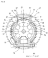
- the toner container 41 includes a first protruding portion 61 (an example of the first lever of the present disclosure) and a second protruding portion 62 (an example of the second lever of the present disclosure).
- the first protruding portion 61 and the second protruding portion 62 are provided on the cover member 56.
- the first protruding portion 61 and the second protruding portion 62 are provided on the support frame 59 of the cover member 56.
- the first protruding portion 61 is supported by the side plate 65 that is disposed on the left side and protrudes leftward from the side plate 65.
- the second protruding portion 62 is supported by the side plate 66 that is disposed on the right side and protrudes rightward from the side plate 66.
- a pair of guide grooves 67 extending in the front-rear direction D2 are formed in each of the side plates 65 and 66 (see FIG. 5 ).
- the guide grooves 67, in each pair, are located away from each other in the up-down direction D1.
- the first protruding portion 61 and the second protruding portion 62 are each attached in such a way as to be slidable (movable) in the corresponding pair of guide grooves 67. This allows the first protruding portion 61 to move in the front-rear direction D2 on the side plates 65, and the second protruding portion 62 to move in the front-rear direction D2 on the side plates 66.
- the first protruding portion 61 includes a base portion 70 and a projection 71, wherein the base portion 70 is slidably supported by the pair of guide grooves 67, and the projection 71 projects in the horizontal direction from the base portion 70.
- the base portion 70 includes two rails 72 that are respectively provided at its upper and lower ends.
- the rails 72 are slidably supported by the guide grooves 67.
- a latch mechanism is provided in the guide grooves 67 and the rails 72, wherein the latch mechanism is configured to temporarily hold the first protruding portion 61 at a first position P1 and a second position P2 that are described below. As a result, when the first protruding portion 61 is moved to any of the first position P1 and the second position P2, the first protruding portion 61 is held at that position by the latch mechanism.
- the support mechanism of the second protruding portion 62 has approximately the same configuration as the support mechanism of the first protruding portion 61, and the second protruding portion 62 includes a base portion 70 and a projection 71.
- the base portion 70 includes two rails 72 provided at the upper and lower ends thereof respectively.
- the rails 72 are slidably supported by the guide grooves 67.
- a latch mechanism is provided in the guide grooves 67 and the rails 72, wherein the latch mechanism is configured to temporarily hold the second protruding portion 62 at a third position P3 and a fourth position P4. As a result, when the second protruding portion 62 is moved to any of the third position P3 and the fourth position P4, the second protruding portion 62 is held at that position by the latch mechanism.
- the first protruding portion 61 is slidable between a predetermined first position P1 (see FIG. 6A to FIG. 6C ) and a second position P2 (see FIG. 6A to FIG. 6C ). In other words, the first protruding portion 61 is configured to switch between the first position P1 and the second position P2.
- the second protruding portion 62 is slidable between a predetermined third position P3 (see FIG. 6A to FIG. 6C ) and a fourth position P4 (see FIG. 6A to FIG. 6C ). In other words, the second protruding portion 62 is configured to switch between the third position P3 and the fourth position P4.
- the first position P1 is a position (an initial position) at which the first protruding portion 61 is disposed initially in an unused toner container 41 in which the container main body 52 is filled with unused toner.
- the third position P3 is a position (an initial position) at which the second protruding portion 62 is disposed initially in an unused toner container 41. That is, in an unused toner container 41 bought by the user, the first protruding portion 61 is disposed at the first position P1, and the second protruding portion 62 is disposed at the third position P3.
- the second position P2 is located more on the front side than the first position P1.
- the second position P2 is located away, by a predetermined interval, from the first position P1 in a removal direction (draw-out direction) D22 in which the toner container 41 is removed from the toner supply device 40.
- the fourth position P4 is located more on the front side than the third position P3. In other words, the fourth position P4 is located away from the third position P3 by a predetermined interval in the removal direction D22.
- the first position P1 and the third position P3 are approximately at the same position in the front-rear direction D2.
- the second position P2 and the fourth position P4 are approximately at the same position in the front-rear direction D2.
- the container attachment portion 42 includes four storage portions 44.
- the storage portions 44 respectively store the toner containers 41 of predetermined colors.
- the rightmost storage portion 44A (an example of the first storage portion of the present disclosure) stores the toner container 41 for black.
- FIG. 2 shows a state where a part of the rear-side portion of the toner container 41 for black is inserted in the storage portion 44.
- empty container 41 a used, empty toner container (hereinafter referred to as "empty container”) 41 can be used as a waste toner container.
- empty container 41 a used, empty toner container
- a part of the empty container 41 is deformed or cut.
- the container 41 cannot be used for the other purposes.
- a fragment broken off from an empty container 41 may remain in the waste toner collecting device 80 and obstruct the attachment or detachment of the waste toner container.
- the toner supply device 40 includes the first actuator 101 (an example of the first actuating portion of the present disclosure), and the waste toner collecting device 80 includes the second actuator 102 (an example of the third actuating portion of the present disclosure).
- a toner container 41 is maintained so that a waste toner container can be smoothly inserted and removed to/from the waste toner collecting device 80, and a same toner container 41 can be used both as a toner container for supplying toner and as a toner container for collecting waste toner, while the toner container 41 having collected the waste toner is prevented from being attached to the toner supply device 40, thereby preventing the waste toner from being reused.
- the storage portion 44A includes the first actuator 101.
- the first actuator 101 is configured to, when a toner container 41 is attempted to be inserted in the storage portion 44A, permit or restrict (prohibit) the attachment of the toner container 41 to the storage portion 44A, depending on the position of the first protruding portion 61.
- the first actuator 101 is mounted on an upper wall portion 45 (an example of the upper wall of the present disclosure) of the storage portion 44A.
- the first actuator 101 permits the attachment of the toner container 41 to the storage portion 44A.
- the first actuator 101 acts on the toner container 41 in the state where the first protruding portion 61 is disposed at the second position P2, and restricts (prohibits) the attachment of the toner container 41 to the storage portion 44A (see FIG. 10B ).
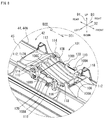
- the first actuator 101 includes a first movable portion 105, a first abutting portion 106, a second abutting portion 107 (see FIG. 9A to FIG. 9C ), and a first biasing member 108.
- the first movable portion 105 includes a pivotal shaft 110 and a base portion 111 that extends from the pivotal shaft 110 in an extension direction D31 that is perpendicular to the pivotal shaft 110.
- the base portion 111 is an approximately rectangular plate member.
- a plurality of ribs 112 are formed on one surface (in FIG. 9A , an upper surface) of the base portion 111, the ribs 112 extending in the extension direction D31.
- the pivotal shaft 110 is pivotably supported by the upper wall portion 45.
- a pair of bearing portions 114 that are located away from each other in the left-right direction D3 are provided on the upper wall portion 45, and the pivotal shaft 110 is pivotably supported by the bearing portions 114.
- an opening 116 is formed more on the front side than the bearing portions 114, the opening 116 communicating with the inside of the storage portion 44A.
- the base portion 111 is inserted in the opening 116 in the state where the pivotal shaft 110 is supported by the bearing portions 114.
- a pair of stoppers 118 are provided on an extension end of the base portion 111, the stoppers 118 extending in the same direction as an axis direction of the pivotal shaft 110.
- the stoppers 118 are hooked to the rim of the opening 116, and a part of the first movable portion 105 enters the opening 116.
- the first movable portion 105 in the entering attitude receives an upward pressing force from the inside of the storage portion 44A, the first movable portion 105 is displaced to a retreating attitude where it has retreated upward from the opening 116. That is, the first actuator 101 is configured to be able to enter from the upper wall portion 45 of the storage portion 44A to the inside of the storage portion 44A and retreat therefrom.
- the first biasing member 108 biases the first movable portion 105 from the upper wall portion 45 toward the inside of the storage portion 44A.
- the first biasing member 108 is attached to the upper wall portion 45.
- the first biasing member 108 is a wire-like steel bent in a rectangular shape.
- Two opposite ends of the first biasing member 108 constitute shafts 108A, and are pivotably attached to the upper wall portion 45.
- a pair of attachment portions 119 are provided in the upper wall portion 45 more on the front side than the bearing portions 114 on the rim of the opening 116.
- the shafts 108A are inserted in and supported by the shaft holes of the attachment portions 119.
- the first biasing member 108 includes arm portions 108B that respectively extend from the shafts 108A, and a straight connection portion 108C that connects the arm portions 108B.
- a rectangular portion is formed by the arm portions 108B and the connection portion 108C.
- a pair of locking pieces 120 are provided on the rim of the opening 116 between the bearing portions 114 and the attachment portions 119, the locking pieces 120 being configured to engage with the arm portions 108B of the first biasing member 108.
- the locking pieces 120 are projecting outward from the rim of the opening 116, and the first biasing member 108 is engaged with the lower surfaces of the locking pieces 120.
- the connection portion 108C of the first biasing member 108 elastically biases the ribs 112 of the first movable portion 105 downward.
- the first biasing member 108 biases the first movable portion 105 toward the entering attitude.
- the first movable portion 105 in the entering attitude receives an upward pressing force from the inside of the storage portion 44A, the first movable portion 105 is displaced from the entering attitude to the retreating attitude against the biasing force of the first biasing member 108.
- first biasing member 108 is not limited to a wire-like member as far as it can elastically bias the first movable portion 105 from the upper wall portion 45 toward the inside of the storage portion 44A.
- Springs and elastic members of various shapes and materials, such as a torsion coil spring and a plate spring, are applicable to the first biasing member 108.
- the first abutting portion 106 is provided in the first movable portion 105.
- the first abutting portion 106 is provided at an end of the base portion 111 in the extension direction D31.
- the first abutting portion 106 is configured to abut on the rear end portion 64A of the upper plate 64 of the support frame 59 of the toner container 41, when the first movable portion 105 is in the entering attitude.
- the first abutting portion 106 includes a locking piece 106A that projects in the extension direction D31 from the rear surface of the first movable portion 105.
- the locking piece 106A enters the rear side of the upper plate 64. This allows the locking piece 106A to engage with the rear end portion 64A of the upper plate 64, thereby preventing the first movable portion 105 from being displaced upward (toward the retreating attitude).
- the second abutting portion 107 is provided in the first movable portion 105.
- the second abutting portion 107 is provided on a rib 112A that is a rib 112 at the leftmost position among the four ribs 112 provided on the base portion 111.
- the second abutting portion 107 is provided at an end of the rib 112A in the extension direction D31, extending from the first abutting portion 106 in the extension direction D31.
- the second abutting portion 107 is an inclined portion having an inclined surface that is inclined from the rear surface of the first movable portion 105 toward the projection end.
- the second abutting portion 107 is configured to abut on the first protruding portion 61 of the support frame 59 of the toner container 41 when the first movable portion 105 is in the entering attitude.
- the first actuator 101 having the above-described configuration is provided in the storage portion 44A, when the toner container 41 is inserted in the storage portion 44A, either the first abutting portion 106 or the second abutting portion 107 abuts on the rear end portion 64A or the first protruding portion 61. Specifically, as shown in FIG. 10A , when the toner container 41 is inserted in the storage portion 44A in the state where the first protruding portion 61 is at the first position P1, the second abutting portion 107 abuts on the first protruding portion 61 before the first abutting portion 106 abuts.
- the first abutting portion 106 does not abut on the rear end portion 64A.
- the second abutting portion 107 receives an upward pressing force from the first protruding portion 61, and the first actuator 101 is displaced upward toward the retreating attitude. This allows the toner container 41 to be inserted in the storage portion 44A without interruption by the first abutting portion 106, to a predetermined attachment position in the storage portion 44A.
- the storage portion 44A includes a first pressing portion 121 (an example of the second actuating portion of the present disclosure).
- the first pressing portion 121 is integrally formed with the inner wall of the storage portion 44A.
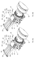
- the first pressing portion 121 acts on and presses the second protruding portion 62 frontward (see FIG. 11A, FIG. 11B ).
- This allows the second protruding portion 62 to move from the third position P3 to the fourth position P4 (see FIG. 11C ). That is, the second protruding portion 62 is switched from the third position P3 to the fourth position P4.
- the empty toner container 41 (hereinafter referred to as an "empty container 41") can be used in the waste toner collecting device 80.
- the empty container 41 to prevent a new, unused toner container 41 from being erroneously attached to the waste toner collecting device 80, it is configured so that a toner container 41 can be attached to the waste toner collecting device 80 only when it has become empty.
- the waste toner collecting device 80 is described with reference to FIG. 12 to FIG. 16C .
- the waste toner collecting device 80 is composed of the waste toner container 81 and a container attachment portion 82 to which the waste toner container 81 is attached.
- FIG. 12 shows a state where the waste toner container 81 is attached to the waste toner collecting device 80.
- the vertical direction is the up-down direction D1
- the attachment/detachment (insertion/removal) direction of the waste toner container 81 to/from the housing 11 is the front-rear direction D2
- the horizontal direction viewed from the front of the waste toner collecting device 80 is the left-right direction D3.
- the waste toner container 81 has the same shape as the toner container 41 that is configured to be attachable to the toner supply device 40.
- the waste toner container 81 is a used, empty toner container (empty container) 41 from which all the toner had been used in the toner supply device 40.
- the waste toner container 81 is a toner container 41 that had been attached to the storage portion 44A, and was removed from the storage portion 44A after it had become empty and the toner therein had been consumed completely.
- a new toner container 41 is in a state (an example of the first state of the present disclosure) where the first protruding portion 61 is disposed at the first position P1 and the second protruding portion 62 is disposed at the third position P3.
- the first protruding portion 61 maintains to be disposed at the first position P1
- the second protruding portion 62 is moved from the third position P3 to the fourth position P4. That is, the second protruding portion 62 is switched from the third position P3 to the fourth position P4.
- an empty container 41 immediately after removed from the storage portion 44A is in a state (an example of the second state of the present disclosure) where the first protruding portion 61 is disposed at the first position P1 and the second protruding portion 62 is disposed at the fourth position P4.
- a toner container 41 in this state can be attached to any of the toner supply device 40 or the waste toner collecting device 80. Since the waste toner container 81 has the same configuration as the toner container 41, in the following, the same reference signs are used and the description of the configuration is omitted.
- the waste toner container 81 is attached to the container attachment portion 82 in the state where the toner discharge port 74 faces up.
- the rotational driving force from a driving source such as a motor is transmitted to the gear 54 in the state where the waste toner container 81 is attached to a predetermined attachment position in the container attachment portion 82.
- a rotational driving force of a second rotation direction (see the arrow D12) is transmitted to the gear 54, wherein the second rotation direction is opposite to a first rotation direction (see the arrow D11) of the toner container 41.
- the waste toner container 81 is rotated in the second rotation direction indicated by the arrow D12.
- the waste toner container 81 is rotated in the second rotation direction (see the arrow D12) opposite to the first rotation direction in the state where the waste toner container 81 is attached to the container attachment portion 82, and the waste toner flows to the toner discharge port 74.
- This allows the waste toner stored in the waste toner container 81 to be pressed by the angled rib 53 and conveyed away from the opening portion 51 (frontward).
- the container attachment portion 82 is configured to store the waste toner container 81 that is attached therto in a detachable manner.
- the container attachment portion 82 is configured to guide the waste toner discharged from the belt cleaning device 6, from the toner discharge port 74 to the inside of the waste toner container 81.
- the waste toner container 81 is configured to be detached from the container attachment portion 82 and attached to the container attachment portion 82 as necessary. Specifically, when the waste toner container 81 is filled with the waste toner or when the amount of waste toner stored therein becomes equal to or larger than a predetermined amount (full amount), the waste toner container 81 is removed by the user. Subsequently, an empty waste toner container 81 is attached by the user.
- the container attachment portion 82 includes a storage portion 84 (an example of the second storage portion of the present disclosure).
- the storage portion 84 stores, as the waste toner container 81, an empty container 41 that had been attached to the storage portion 44A of the toner supply device 40.
- the storage portion 84 includes the second actuator 102.
- the second actuator 102 is configured to, when a waste toner container 81 is attempted to be inserted in the storage portion 84, permit or restrict (prohibit) the attachment of the waste toner container 81 to the storage portion 84, depending on the position of the second actuator 102.
- the second actuator 102 is mounted on a lower wall portion 85 (an example of the lower wall of the present disclosure) of the storage portion 84.
- the second actuator 102 permits the attachment of the waste toner container 81 to the storage portion 84.
- the second actuator 102 restricts (prohibits) the attachment of the waste toner container 81 to the storage portion 84 if the second protruding portion 62 is disposed at the third position P3.
- the second actuator 102 acts on the second protruding portion 62 disposed at the third position P3 and restricts (prohibits) the attachment of the waste toner container 81 to the storage portion 84.
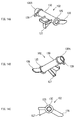
- the second actuator 102 includes a second movable portion 125, a first projection piece 126, a second projection piece 127, and a second biasing member 128.
- the second movable portion 125 includes a pivotal shaft 130.
- the pivotal shaft 130 is pivotably supported by the lower wall portion 85.
- a pair of bearing portions 134 that are located away from each other in the left-right direction D3 are provided on the lower wall portion 85, and the pivotal shaft 130 is pivotably supported by the bearing portions 134.
- the second movable portion 125 is supported by the lower wall portion 85 in such a way as to be pivotable around the pivotal shaft 130.
- Two openings 136 and 137 are formed in the lower wall portion 85.
- the opening 136 is formed more on the rear side than the bearing portions 134, the opening 136 communicating with the inside of the storage portion 84.
- the opening 137 is formed more on the front side than the bearing portions 134, the opening 137 communicating with the inside of the storage portion 84.
- the second movable portion 125 includes the first projection piece 126, the second projection piece 127, and the second biasing member 128.
- the first projection piece 126 projects outward from the pivotal shaft 130 in its radial direction.
- the second projection piece 127 projects outward from the pivotal shaft 130 in a radial direction thereof that is different from the projection direction of the first projection piece 126.
- the angle between the first projection piece 126 and the second projection piece 127 is set to be approximately 120 degrees.
- the first projection piece 126 can be inserted in the storage portion 84 from the lower wall portion 85 via the opening 136.
- the first projection piece 126 can be displaced to an entering attitude or to a retreating attitude, wherein in the entering attitude, the first projection piece 126 has entered the inside of the storage portion 84 from the opening 136, and in the retreating attitude, the first projection piece 126 has retreated from the inside of the storage portion 84. That is, the second actuator 102 is configured such that the second movable portion 125 can enter from the lower wall portion 85 of the storage portion 84 to the inside of the storage portion 84 and retreat therefrom.
- the second projection piece 127 when the first projection piece 126 is in a state (entering attitude) of having entered the inside of the storage portion 84 from the opening 136, the second projection piece 127 is in a state (retreating attitude) of having retreated from the opening 137 of the lower wall portion 85 to outside. Furthermore, when the first projection piece 126 retreats from the opening 136 to outside, the second projection piece 127 enters the inside of the storage portion 84 and is engaged with the opening 59A of the support frame 59.
- the second biasing member 128 biases the first projection piece 126 from the lower wall portion 85 toward the inside of the storage portion 84 via the opening 136.
- the second biasing member 128 is a torsion coil spring attached to an end portion 130A of the pivotal shaft 130. Near the end portion 130A, there is provided an attachment portion 139 to which an end of the second biasing member 128 is attached, and the other end abuts on the second movable portion 125 and biases the first projection piece 126 together with the second movable portion 125. That is, the second biasing member 128 biases the first projection piece 126 toward the entering attitude.
- the second actuator 102 pivots, and the first projection piece 126 retreats from the opening 136 to outside.
- the second projection piece 127 enters the inside of the storage portion 84 from the opening 137.
- the second biasing member 128 is not limited to a torsion coil spring as far as it can elastically bias the first projection piece 126 of the second movable portion 125 from the lower wall portion 85 toward the inside of the storage portion 84.
- Springs and elastic members of various shapes and materials, such as a plate spring, are applicable to the second biasing member 128.
- the second actuator 102 having the above-described configuration is provided in the storage portion 84, when the waste toner container 81 is inserted in the storage portion 84, the second protruding portion 62 of the support frame 59 abuts on the first projection piece 126. This causes the second actuator 102 to pivot, and the first projection piece 126 retreats from the opening 136 to outside.
- the second actuator 102 permits the insertion of the waste toner container 81 in the storage portion 84.
- the second actuator 102 acts on the second protruding portion 62 that is disposed at the third position P3, and restricts (prohibits) the attachment of the waste toner container 81.
- the second protruding portion 62 abuts on and causes the second actuator 102 to pivot.
- the first projection piece 126 projects from the opening 136 to outside of the lower wall portion 85, and the second projection piece 127 enters the inside of the storage portion 84.
- the second projection piece 127 enters the opening 59A and is engaged with the opening 59A.
- the second projection piece 127 restricts (prohibits) the toner container 41 from being inserted in the storage portion 84. This makes it possible to prevent a new, unused toner container 41 from being erroneously attached to the waste toner collecting device 80.
- the storage portion 84 includes a second pressing portion 142 (an example of the fourth actuating portion of the present disclosure).
- the second pressing portion 142 is a projection-like member that is integrally formed with the inner wall of the storage portion 84.
- the second pressing portion 142 acts on and switches the first protruding portion 61 disposed at the first position P1 to the second position P2 (see FIG. 16C ).
- the second pressing portion 142 presses the first protruding portion 61 frontward as the waste toner container 81 is attached to the storage portion 84 (see FIG. 16A, FIG. 16B ).
- an empty container 41 that has become empty with the toner therein having been consumed completely in the toner supply device 40 can be used as a waste toner container 81.
- the waste toner container 81 becomes full of waste toner, the waste toner container 81 is removed from the waste toner collecting device 80.
- the waste toner container 81 is configured such that it cannot be attached to the toner supply device 40 again.
- the waste toner container 81 having been removed from the waste toner collecting device 80 is in the state (an example of the third state of the present disclosure) where the first protruding portion 61 has been moved from the first position P1 to the second position P2 by the second pressing portion 142.
- the waste toner container 81 is restricted (prohibited) by the first actuator 101 from being inserted in the storage portion 44A (see FIG. 11A to FIG. 11C ).
- a removed waste toner container 81 cannot be attached to the storage portion 44A if it is in the state where the first protruding portion 61 is disposed at the second position P2. As a result, it is possible to prevent waste toner from being used by preventing the waste toner container 81 from being re-attached.
- the second embodiment of the present disclosure is different from the first embodiment in that a stopper member 200 is provided in the waste toner collecting device 80. Otherwise, the first and second embodiments have a common configuration. Accordingly, in the following description, description of the configuration common to the first and second embodiments is omitted.
- FIG. 17 is a partial perspective view showing a configuration of a rear end portion of the storage portion 84 of the waste toner collecting device 80.
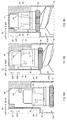
- FIG. 18A to FIG. 18C are schematic cross sectional views taken along a cut plane XVIII-XVIII of FIG. 17 and show an operational relationship between the second protruding portion 62 and the stopper member 200.
- the stopper member 200 is attached to the rear end side of the storage portion 84.
- the stopper member 200 is configured to be attachable to and detachable from a left side wall 84A on the rear end side of the storage portion 84 at either of predetermined two attachment positions (a first attachment position P11 and a second attachment position P12).
- Two rectangular openings 201 and 202 are formed in the left side wall 84A.
- the openings 201 and 202 are used to attach the stopper member 200 to the storage portion 84.
- the openings 201 and 202 are configured to position the stopper member 200 attached to the storage portion 84 to either the first attachment position P11 or the second attachment position P12.
- the openings 201 and 202 are formed at positions located away from each other in the front-rear direction D2.
- the opening 201 is formed more on the downstream side in an opposite direction to a direction in which the waste toner container 81 is inserted in the storage portion 84 (in FIG. 17 , more on the front side) than the opening 202.
- the opening 202 is formed at a position that is (in FIG. 17 , on the rear side) located away from the opening 201 by a predetermined distance in the direction in which the waste toner container 81 is inserted in the storage portion 84.
- the stopper member 200 is configured to, when the waste toner container 81 is inserted in the storage portion 84, permit or restrict (prohibit) the attachment of the waste toner container 81 to the storage portion 84, depending on the position of the second protruding portion 62.
- the second actuator 102 in the first embodiment is also configured to permit or restrict the attachment of the waste toner container 81 to the storage portion 84.
- the stopper member 200 is configured to restrict the insertion of the waste toner container 81 even when the second actuator 102 permits the insertion of the waste toner container 81.
- the stopper member 200 has an elongated shape.
- the stopper member 200 includes a protruding portion 205 at one end (a front end in FIG. 17 ) in the longitudinal direction thereof, wherein the protruding portion 205 has an approximately square shape and can be inserted in the opening 201 and the opening 202 one at a time.
- the stopper member 200 includes a gripping portion 209 at the other end (a rear end in FIG. 17 ) in the longitudinal direction thereof.
- the gripping portion 209 is a portion that is gripped by the worker when, as described below, the worker attaches the stopper member 200 to the first attachment position P11 or the second attachment position P12.
- the stopper member 200 includes an arm portion 206 that extends from the protruding portion 205 to the gripping portion 209.
- a long hole 207 is formed in the arm portion 206, wherein the long hole 207 is a long, rectangular through hole extending in the extension direction of the arm portion 206.
- the arm portion 206 also includes two engaging portions 206A and 206B that are bar-like members located away from each other in the width direction thereof. The engaging portions 206A and 206B are located away from each other in the width direction with the long hole 207 of the arm portion 206 in between.
- a plurality of engaging claws 208 are provided on the left side wall 84A of the storage portion 84, wherein the engaging claws 208 are used to attach the engaging portions 206A and 206B of the arm portion 206 to the left side wall 84A.
- the engaging claws 208 are located more on the downstream side in the direction in which the waste toner container 81 is inserted in the storage portion 84 (in FIG. 17 , more on the rear side) than the opening 202.
- the engaging claws 208 are formed at a rear end of the left side wall 84A on the downstream side in the insertion direction.
- the arm portion 206 When the engaging portions 206A and 206B of the arm portion 206 enter the gaps between the engaging claws 208 and are engaged with the engaging claws 208, the arm portion 206 is attached to the left side wall 84A.
- the stopper member 200 is attached to the left side wall 84A when the protruding portion 205 is inserted in the opening 201 or the opening 202 in the state where the arm portion 206 is engaged with the engaging claws 208.
- the stopper member 200 when attached in the state where the protruding portion 205 is inserted in the opening 201, the stopper member 200 is positioned to the first attachment position P11. That is, the stopper member 200 is attached to the first attachment position P11.
- the stopper member 200 when attached in the state where the protruding portion 205 is inserted in the opening 202, the stopper member 200 is positioned to the second attachment position P12. That is, the stopper member 200 is attached to the second attachment position P12.
- the stopper member 200 is removed from the left side wall 84A.
- the positional change between the first attachment position P11 and the second attachment position P12 is performed while the arm portion 206 is engaged with the engaging claws 208.
- FIG. 18A to FIG. 18C schematic diagrams of FIG. 18A to FIG. 18C . It is noted that in FIG. 18A to FIG. 18C , for convenience of explanation, only the first protruding portion 61 and the second protruding portion 62 of the waste toner container 81 are represented by a real line, and the other portions of the waste toner container 81 are represented by a dotted line.
- FIG. 18A shows an operation example in a case where a waste toner container 81 is attempted to be inserted in the storage portion 84 in a state where the stopper member 200 has been attached to the first attachment position P11 and the first protruding portion 61 and the second protruding portion 62 are disposed at the first position P1 and the fourth position P4, respectively. As shown in FIG.
- the protruding portion 205 abuts on the second protruding portion 62.
- the second protruding portion 62 can move to the third position P3, but while being disposed at the fourth position P4, cannot move to a side opposite to the third position P3.
- the second protruding portion 62 at the fourth position P4 abuts on the protruding portion 205 of the stopper member 200, the movement of the waste toner container 81 toward the attachment direction with regard to the storage portion 84 is restricted. This restricts (prohibits) the attachment of the waste toner container 81 to the storage portion 84.
- the worker in response to the user's request, changes the attachment position of the stopper member 200 to the first attachment position P11 in advance. This makes it possible to prohibit the empty container 41 from being used as the waste toner container 81 in the image forming apparatus 10. It is noted that in that case, the user needs to buy a waste toner container dedicated to collecting the waste toner and attach it to the storage portion 84, wherein the dedicated waste toner container can be attached to the attachment position of the storage portion 84 without being restricted by the stopper member 200. In addition, the user needs to store an unused, dedicated waste toner container for replacement in case the dedicated waste toner container becomes full of waste toner.
- FIG. 18B shows a waste toner container 81 in which the stopper member 200 has been attached to the second attachment position P12 and the first protruding portion 61 and the second protruding portion 62 are disposed at the first position P1 and the fourth position P4, respectively.
- the following describes an operation example where this waste toner container 81 is attempted to be inserted in the storage portion 84. As shown in FIG.
- the protruding portion 205 does not abut on the second protruding portion 62.
- the waste toner container 81 is inserted to the attachment position of the storage portion 84 without being restricted by the stopper member 200. It is noted that, as shown in FIG. 18C , during the insertion process, the first protruding portion 61 is moved from the first position P1 to the second position P2 by the second pressing portion 142.
- the stopper member 200 can be attached to either the first attachment position P11 or the second attachment position P12.
- the image forming apparatus 10 it is possible to perform a setting to restrict the attachment of the toner container 41 to the waste toner collecting device 80 or perform a setting to permit the attachment of the toner container 41 to the waste toner collecting device 80, depending on the use form of the image forming apparatus 10.
- the user may use the image forming apparatus 10 in which the stopper member 200 has been attached to the first attachment position P11, thereby preventing the toner container 41 from being erroneously attached to the storage portion 84.
Landscapes
- Physics & Mathematics (AREA)
- General Physics & Mathematics (AREA)
- Life Sciences & Earth Sciences (AREA)
- Engineering & Computer Science (AREA)
- Environmental & Geological Engineering (AREA)
- Sustainable Development (AREA)
- Cleaning In Electrography (AREA)
- Dry Development In Electrophotography (AREA)
- Electrophotography Configuration And Component (AREA)
Abstract
Description
- The present disclosure relates to an image forming apparatus to which a toner container storing toner for supply and a toner container for storing collected waste toner can be attached.
- A developing device is mounted in an electrophotographic image forming apparatus. Developer containing toner is stored inside the developing device. The developing device develops an electrostatic latent image formed on an image carrying member such as a photoconductor drum, by the toner contained in the developer. A toner image developed on the image carrying member is fixed to a print sheet by a fixing device. After the fixing, toner that was not fixed to the print sheet by the fixing device may remain on the image carrying member. With regard to this problem, there is known a waste toner collecting device for removing the toner remaining on the image carrying member and collecting the toner as waste toner.
- The waste toner collecting device of this type includes a waste toner container for storing removed waste toner. Conventionally, there is known an image forming apparatus that can use, as a waste toner container, a toner supply container that had been used to supply toner to the developing device and had become empty.
- Meanwhile, in the conventional image forming apparatus, when an empty toner supply container is used as a waste toner container, it is necessary to reserve the empty container. Since the empty container is a used toner suppy container, toner is adhered to a toner supply port or the like. As a result, to prevent floating toner and smear of toner while an empty container is reserved, the empty container needs to be sealed in a bag or the like. This is troublesome to the user. In addition, when removing the empty container from the bag or the like, toner may be scattered to smear the surrounding. A user who dislikes such a smear prefers the use of a dedicated waste toner container provided to collect the waste toner, rather than an empty container of a toner supply container.
- An image forming apparatus according to an aspect of the present disclosure includes a toner supply portion, a waste toner collecting portion, and a toner container. The toner container is configured to be attachable to and detachable from the toner supply portion and the waste toner collecting portion. The toner container includes a second lever configured to be switchable between a third position and a fourth position. The toner supply portion includes a second actuating portion. The second actuating portion is configured to, during a process in which the toner container is attached to the toner supply portion, act on the second lever disposed at the third position and switch the second lever to the fourth position. The waste toner collecting portion includes a third actuating portion and a stopper member. The third actuating portion is configured to, during a process in which the toner container is attached to the waste toner collecting portion, act on the second lever disposed at the third position and prohibit an attachment of the toner container, and act on the second lever disposed at the fourth position and permit an attachment of the toner container. The stopper member is attachable to either a first attachment position or a second attachment position and configured to, in a state of having been attached to the first attachment position, act on the second lever disposed at the fourth position and prohibit an attachment of the toner container, and in a state of having been attached to the second attachment position, permit an attachment of the toner container in which the second lever is disposed at the fourth position.
- This Summary is provided to introduce a selection of concepts in a simplified form that are further described below in the Detailed Description with reference where appropriate to the accompanying drawings. This Summary is not intended to identify key features or essential features of the claimed subject matter, nor is it intended to be used to limit the scope of the claimed subject matter. Furthermore, the claimed subject matter is not limited to implementations that solve any or all disadvantages noted in any part of this disclosure.
-
-
FIG. 1 is a diagram showing an image forming apparatus according to an embodiment of the present disclosure. -
FIG. 2 is a perspective view of a toner supply device included in the image forming apparatus. -
FIG. 3 is a perspective view of a toner container included in the image forming apparatus. -
FIG. 4 is an enlarged perspective view of a cover member of the toner container. -
FIG. 5 is a diagram showing the cover member of the toner container. -
FIG. 6A, FIG. 6B, and FIG. 6C are diagrams for explaining the operation of a protruding portion of the cover member of the toner container. -
FIG. 7 is a cross section of the cover member of the toner container. -
FIG. 8 is an enlarged perspective view of a first actuator included in a toner supply device. -
FIG. 9A, FIG. 9B, and FIG. 9C are diagrams showing a configuration of the first actuator. -
FIG. 10A and FIG. 10B are diagrams showing an operational relationship between the first actuator and a first protruding portion of the cover member. -
FIG. 11A, FIG. 11B, and FIG. 11C are diagrams showing an operational relationship between a second protruding portion of the cover member and a first pressing portion. -
FIG. 12 is a perspective view of a waste toner collecting device included in the image forming apparatus. -
FIG. 13 is an enlarged perspective view of a second actuator included in the waste toner collecting device. -
FIG. 14A, FIG. 14B, and FIG. 14C are diagrams showing a configuration of the second actuator. -
FIG. 15A and FIG. 15B are diagrams showing an operational relationship between the second actuator and the second protruding portion of the cover member. -
FIG. 16A, FIG. 16B, and FIG. 16C are diagrams showing an operational relationship between the first protruding portion of the cover member and a second pressing portion. -
FIG. 17 is a partial perspective view showing a configuration of a rear end portion of a storage portion of the waste toner collecting device. -
FIG. 18A, FIG. 18B, and FIG. 18C are schematic cross sectional views taken along a cut plane XVIII-XVIII ofFIG. 17 and show an operational relationship between the second protruding portion and a stopper member. - The following describes, with reference to the drawings, an
image forming apparatus 10 according to a first embodiment of the present disclosure. For the sake of explanation in the following description, an up-down direction D1 is defined based on the state where theimage forming apparatus 10 is installed. In addition, a front-rear direction D2 is defined such that a side at which insertion of atoner container 41 and awaste toner container 81 to theimage forming apparatus 10 is performed is the front side. Furthermore, a left-right direction D3 is defined based on theimage forming apparatus 10 viewed from the front side. - The
image forming apparatus 10 has at least a print function and is, for example, a color printer. Theimage forming apparatus 10 prints an image on a print sheet that is a sheet member, by using developer containing toner. It is noted that a specific example of theimage forming apparatus 10 according to the embodiments of the present disclosure is, for example, a printer, a copier, a facsimile, or a multifunction peripheral having functions of these apparatuses. In addition, although theimage forming apparatus 10 is configured to form a color image, the image forming apparatus of the present disclosure may be configured to form a monochrome image. - As shown in
FIG. 1 , theimage forming apparatus 10 is a so-called tandem color image forming apparatus. Theimage forming apparatus 10 includes a plurality ofimage forming portions 1 to 4, anintermediate transfer unit 5, an exposure device 14, asecondary transfer device 15, a fixingdevice 16, a toner supply device 40 (an example of the toner supply portion of the present disclosure), abelt cleaning device 6, a waste toner collecting device 80 (an example of the waste toner collecting portion of the present disclosure), an operation/display portion 9 including a touch panel, a liquid crystal display portion and the like, a control portion 8, asheet feed tray 17, and asheet discharge tray 18. These components are attached to ahousing 11 that constitutes an external frame (not shown), an internal frame and the like of theimage forming apparatus 10. - The
image forming portions 1 to 4 respectively form toner images of different colors on a plurality ofphotoconductor drums 21 that are arranged in alignment, by a so-called electrophotography. The toner images are transferred to anintermediate transfer belt 5A while it is running (moving) such that the toner images are overlaid with each other. In the example shown inFIG. 1 , theimage forming portions 1 to 4 for black, yellow, cyan, and magenta are arranged in alignment in the stated order from the downstream side in the moving direction (direction indicated by the arrow 19) of theintermediate transfer belt 5A. - The
image forming portions 1 to 4 are provided below theintermediate transfer belt 5A. Each of theimage forming portions 1 to 4 includes aphotoconductor drum 21 carrying a toner image thereon, a chargingdevice 22, a developingdevice 23, and aprimary transfer device 24. The surface of thephotoconductor drum 21 is charged by the chargingdevice 22, and the charged surface of thephotoconductor drum 21 is exposure-scanned by the exposure device 14. This allows an electrostatic latent image to be formed on the surface of thephotoconductor drum 21. The developingdevice 23 develops the electrostatic latent image with the toner. Subsequently, the toner image on thephotoconductor drum 21 is transferred to theintermediate transfer belt 5A by theprimary transfer device 24. - The
intermediate transfer unit 5 includes theintermediate transfer belt 5A, a drivingroller 7A, and a drivenroller 7B. Theintermediate transfer belt 5A carries a toner image that is formed from toner images of a plurality of (in the present embodiment, four) colors. Theintermediate transfer belt 5A is supported and rotationally driven by the drivingroller 7A and the drivenroller 7B so as to move while its surface is in contact with surfaces of the photoconductor drums 21. When theintermediate transfer belt 5A is rotationally driven, its surface passes between the photoconductor drums 21 and theprimary transfer devices 24. During that movement, the toner images of the different colors carried on the plurality ofphotoconductor drum 21 are transferred in sequence to theintermediate transfer belt 5A in such a way as to be overlaid with each other. - The
toner supply device 40 is provided above theintermediate transfer unit 5. Thetoner supply device 40 is configured to store fourtoner containers 41 for colors of black, yellow, cyan, and magenta that are attached thereto in a detachable manner. The configuration of thetoner supply device 40 is described below. - The
secondary transfer device 15 transfers the toner image from theintermediate transfer belt 5A to a print sheet conveyed from thesheet feed tray 17. The print sheet on which the toner image is transferred is conveyed by a conveyance portion (not illustrated) to the fixingdevice 16. The fixingdevice 16 includes aheating roller 16A and apressure roller 16B. The fixingdevice 16 conveys the print sheet on which the toner image has been transferred, while applying heat and pressure thereto. This allows the toner image to be fused and fixed to the print sheet. The print sheet to which the toner image has been fixed is further conveyed toward the downstream side, and discharged to and held by thesheet discharge tray 18 that is disposed above theintermediate transfer unit 5. - The
belt cleaning device 6 collects waste toner, namely toner that has remained on the surface of theintermediate transfer belt 5A, and conveys the collected waste toner to the wastetoner collecting device 80. Thebelt cleaning device 6 is disposed on the left side of theintermediate transfer unit 5. Thebelt cleaning device 6 includes a cleaningroller 25 that is the cleaning member, ascrew member 26, and atoner box 27. The cleaningroller 25 is disposed to face the drivenroller 7B, and its surface is in contact with theintermediate transfer belt 5A. The length of the cleaningroller 25 in the front-rear direction D2 is approximately the same as that of theintermediate transfer belt 5A. The cleaningroller 25 is rotatably supported in thetoner box 27. The cleaningroller 25 is rotated when a rotational driving force is input to the shaft of the cleaningroller 25. - The cleaning
roller 25 is rotated while it is in contact with theintermediate transfer belt 5A, thereby removing toner that has remained on the surface of theintermediate transfer belt 5A after the transfer by thesecondary transfer device 15. Hereinafter, the toner that has been removed by the cleaningroller 25 is referred to as "waste toner". The waste toner is taken into thetoner box 27 by the action of gravity or by the rotation of the cleaningroller 25, and collected therein. The waste toner collected in thetoner box 27 is conveyed by thescrew member 26. A discharge port (not illustrated) is formed on the bottom of thetoner box 26 on the rear end side. The waste toner is conveyed in thetoner box 27 toward the discharge port as thescrew member 26 is rotated. - The waste
toner collecting device 80 is provided below thetoner box 27. The wastetoner collecting device 80 is configured to store thewaste toner container 81 that is attached thereto in a detachable manner. When the waste toner is discharged from the discharge port of thebelt cleaning device 6, the waste toner is reserved in thewaste toner container 81 attached to the wastetoner collecting device 80. That is, the toner that has remained on the surface of theintermediate transfer belt 5A is removed by thebelt cleaning device 6 and then stored in thewaste toner container 81 as the waste toner. In the present embodiment, anempty toner container 41 that was used in thetoner supply device 40 can be used as thewaste toner container 81 as well. The wastetoner collecting device 80 is described below. - In the following, the
toner supply device 40 is described with reference toFIG. 2 to FIG. 11C . As shown inFIG. 2 , thetoner supply device 40 includestoner containers 41 and acontainer attachment portion 42 to which thetoner containers 41 are attached. It is noted that in these drawings, based on the attachment attitude where thetoner supply device 40 is attached to thehousing 11, the vertical direction is defined as the up-down direction D1, the attachment/detachment (insertion/removal) direction of thetoner containers 41 to/from thehousing 11 is defined as the front-rear direction D2, and the horizontal direction viewed from the front of thetoner supply device 40 is defined as the left-right direction D3. - The
toner containers 41 store toner that is to be supplied to the developingdevice 23. In the present embodiment, fourtoner containers 41 corresponding to the colors of black, yellow, cyan and magenta are provided in thetoner supply device 40. It is noted that thetoner container 41 for black has a larger external diameter than thetoner containers 41 for the other colors, but except for this, all thetoner containers 41 have the same configuration. In the following description, thetoner container 41 refers to thetoner container 41 for black unless otherwise mentioned. - The
toner container 41 is elongated in the front-rear direction D2. The inside of thetoner container 41 is a storage space for storing toner. Thetoner container 41 includes a containermain body 52, adrive transmission portion 55, and acover member 56. The containermain body 52 is cylindrical, wherein an opening portion 51 (seeFIG. 7 ) through which toner can flow in and out is formed at one (a rear end) of opposite ends thereof, and the other end (a front end) is closed. The rear-end portion of the containermain body 52 is formed in a tapered shape, and the openingportion 51 is formed at the rear end thereof. The openingportion 51 is circular in a cross section. The inside of the containermain body 52 is a storage space for storing toner. Toner is stored in the containermain body 52. The containermain body 52 is made of, for example, a synthetic resin such as polyethylene terephthalate (PET resin). - The container
main body 52 includes anangled rib 53 that is formed in a spiral shape on the inner surface of the container main body 52 (seeFIG. 3 ,FIG. 7 ). Theangled rib 53 projects from the inner surface of the containermain body 52 toward the center of the containermain body 52. Theangled rib 53 has a role of conveying the toner in the containermain body 52 toward the opening portion 51 (seeFIG. 7 ). - As shown in
FIG. 4 , thedrive transmission portion 55 is attached to the openingportion 51 side of the containermain body 52. Thedrive transmission portion 55 is fixed to the containermain body 52. Thedrive transmission portion 55 is an annular member with agear 54 formed on its circumferential surface. Upon receiving a rotational driving force from a drive source such as a motor, thedrive transmission portion 55 transmits the rotational driving force to thetoner container 41. - In the container
main body 52, thecover member 56 is provided more on the rear side than thedrive transmission portion 55. Thecover member 56 is provided to cover theopening portion 51. Thecover member 56 includes astorage frame 58 of a cylindrical shape in which the opening portion 51 (seeFIG. 7 ) is inserted. As shown inFIG. 7 , the openingportion 51 is inserted in thestorage frame 58, thus the openingportion 51 is covered. Thestorage frame 58 supports the openingportion 51 in such a manner that the openingportion 51 can pivot in the circumferential direction. As a result, in the state where the openingportion 51 is inserted in thestorage frame 58, the containermain body 52 can pivot in the circumferential direction. That is, thecover member 56 supports the openingportion 51 side of the containermain body 52 in such a manner that the containermain body 52 can pivot. Arear end portion 55A of the drive transmission portion 55 (seeFIG. 7 ) is loosely fitted into afront end portion 56A of thecover member 56. As a result, when the rotational driving force is transmitted to thegear 54 in the state where thetoner container 41 is attached to thecontainer attachment portion 42, the containermain body 52 is rotated by the rotational driving force, in a rotation direction indicated by the arrow D11 (seeFIG. 4 ). That is, thetoner container 41 rotates around its longitudinal direction in the state where toner can be supplied to the developingdevice 23. When the containermain body 52 of thetoner container 41 rotates in this way, the toner is pressed by theangled rib 53 and conveyed toward the openingportion 51 side (the rear side). - The
cover member 56 includes a toner discharge port 74 (seeFIG. 7 ). Thetoner discharge port 74 is provided to discharge the toner from the inside of the containermain body 52 to the outside, and is provided in the outer circumferential wall of thecover member 56. Thetoner discharge port 74 is provided below thecover member 56 inFIG. 7 . Specifically, thetoner discharge port 74 is a rectangular through hole penetrating through the wall of thecover member 56. As shown inFIG. 7 , atoner flow path 75 is formed between the openingportion 51 and thetoner discharge port 74 inside thecover member 56. When thetoner container 41 is attached to the container attachment portion 42 (seeFIG. 2 ) with thetoner discharge port 74 on the lower side, the toner, having moved from the openingportion 51 of the containermain body 52 to thetoner flow path 75, moves through thetoner flow path 75 downward and reaches thetoner discharge port 74. Here, when thetoner discharge port 74 is opened, the toner is discharged from thetoner discharge port 74 to the lower outside. This allows the toner to be supplied to the developingdevice 23. On the other hand, when thetoner discharge port 74 is closed, the toner is not discharged, and thetoner flow path 75 is filled with toner. - As shown in
FIG. 7 , thecover member 56 includes a slide-type opening/closingportion 76. The opening/closingportion 76 is a plate-like member, and is supported by thecover member 56 in such a way as to be slidable in the longitudinal direction of the container main body 52 (the front-rear direction D2). The opening/closingportion 76 opens or closes thetoner discharge port 74 depending on the position of thetoner container 41 with respect to thecontainer attachment portion 42. When thetoner container 41 is attached to thecontainer attachment portion 42, the opening/closingportion 76 opens thetoner discharge port 74. Specifically, when thetoner container 41 is attached to thecontainer attachment portion 42, the opening/closingportion 76 receives, from thecontainer attachment portion 42, a pressing force that is generated by the attachment operation, and is moved to a position (opening position) where the opening/closingportion 76 opens thetoner discharge port 74.FIG. 7 shows a state where the opening/closingportion 76 has moved to the front side and opened thetoner discharge port 74. When thetoner container 41 is removed from thecontainer attachment portion 42, the opening/closingportion 76 is moved rearward by the removal operation, from the opening position to a position (closing position) where the opening/closingportion 76 closes thetoner discharge port 74. It is noted that thecontainer attachment portion 42 includes a biasing member (not illustrated), and the movement of the opening/closingportion 76 from the opening position to the closing position is realized as the biasing member causes the opening/closingportion 76 to move relatively rearward in response to the removal operation of thetoner container 41. - The
cover member 56 includes a support frame 59 (an example of the support portion of the present disclosure). Thesupport frame 59 is disposed on an opposite side to the toner discharge port 74 (on the upper side inFIG. 7 ) in thecover member 56. Thesupport frame 59 is integrally formed with thecover member 56. As shown inFIG. 4 , thesupport frame 59 includes a rectangularupper plate 64 and a pair ofside plates 65 and 66 (an example of the pair of support surfaces of the present disclosure). Theside plates side plates upper plate 64 that are opposite in the left-right direction D3, and the lower ends of theside plates storage frame 58. Arear end portion 64A of theupper plate 64 is configured to abut on a firstabutting portion 106 that is included in a first actuator 101 (an example of the first actuating portion of the present disclosure) that is described below. - The
support frame 59 includes anopening 59A (an example of the restriction portion of the present disclosure) between theside plate 65 and theside plate 66. Theopening 59A is a through hole formed in theupper plate 64. Theopening 59A faces alower wall portion 85 of the wastetoner collecting device 80 when thetoner container 41 is inserted in the wastetoner collecting device 80 along an attachment direction D21 with theupper plate 64 on the lower side. When thetoner container 41 is inserted in this state, a second actuator 102 (an example of the third actuating portion of the present disclosure) is engaged with theopening 59A, thereby the insertion of thetoner container 41 is restricted (prohibited), wherein thesecond actuator 102 is described below. - The
toner container 41 includes a first protruding portion 61 (an example of the first lever of the present disclosure) and a second protruding portion 62 (an example of the second lever of the present disclosure). The first protrudingportion 61 and the second protrudingportion 62 are provided on thecover member 56. Specifically, the first protrudingportion 61 and the second protrudingportion 62 are provided on thesupport frame 59 of thecover member 56. The first protrudingportion 61 is supported by theside plate 65 that is disposed on the left side and protrudes leftward from theside plate 65. The second protrudingportion 62 is supported by theside plate 66 that is disposed on the right side and protrudes rightward from theside plate 66. - A pair of
guide grooves 67 extending in the front-rear direction D2 are formed in each of theside plates 65 and 66 (seeFIG. 5 ). Theguide grooves 67, in each pair, are located away from each other in the up-down direction D1. The first protrudingportion 61 and the second protrudingportion 62 are each attached in such a way as to be slidable (movable) in the corresponding pair ofguide grooves 67. This allows the first protrudingportion 61 to move in the front-rear direction D2 on theside plates 65, and the second protrudingportion 62 to move in the front-rear direction D2 on theside plates 66. - Specifically, as shown in
FIG. 5 , the first protrudingportion 61 includes abase portion 70 and aprojection 71, wherein thebase portion 70 is slidably supported by the pair ofguide grooves 67, and theprojection 71 projects in the horizontal direction from thebase portion 70. Thebase portion 70 includes tworails 72 that are respectively provided at its upper and lower ends. Therails 72 are slidably supported by theguide grooves 67. It is noted that a latch mechanism is provided in theguide grooves 67 and therails 72, wherein the latch mechanism is configured to temporarily hold the first protrudingportion 61 at a first position P1 and a second position P2 that are described below. As a result, when the first protrudingportion 61 is moved to any of the first position P1 and the second position P2, the first protrudingportion 61 is held at that position by the latch mechanism. - The support mechanism of the second protruding
portion 62 has approximately the same configuration as the support mechanism of the first protrudingportion 61, and the second protrudingportion 62 includes abase portion 70 and aprojection 71. Thebase portion 70 includes tworails 72 provided at the upper and lower ends thereof respectively. Therails 72 are slidably supported by theguide grooves 67. It is noted that a latch mechanism is provided in theguide grooves 67 and therails 72, wherein the latch mechanism is configured to temporarily hold the second protrudingportion 62 at a third position P3 and a fourth position P4. As a result, when the second protrudingportion 62 is moved to any of the third position P3 and the fourth position P4, the second protrudingportion 62 is held at that position by the latch mechanism. - The first protruding
portion 61 is slidable between a predetermined first position P1 (seeFIG. 6A to FIG. 6C ) and a second position P2 (seeFIG. 6A to FIG. 6C ). In other words, the first protrudingportion 61 is configured to switch between the first position P1 and the second position P2. The second protrudingportion 62 is slidable between a predetermined third position P3 (seeFIG. 6A to FIG. 6C ) and a fourth position P4 (seeFIG. 6A to FIG. 6C ). In other words, the second protrudingportion 62 is configured to switch between the third position P3 and the fourth position P4. The first position P1 is a position (an initial position) at which the first protrudingportion 61 is disposed initially in anunused toner container 41 in which the containermain body 52 is filled with unused toner. In addition, the third position P3 is a position (an initial position) at which the second protrudingportion 62 is disposed initially in anunused toner container 41. That is, in anunused toner container 41 bought by the user, the first protrudingportion 61 is disposed at the first position P1, and the second protrudingportion 62 is disposed at the third position P3. The second position P2 is located more on the front side than the first position P1. In other words, the second position P2 is located away, by a predetermined interval, from the first position P1 in a removal direction (draw-out direction) D22 in which thetoner container 41 is removed from thetoner supply device 40. The fourth position P4 is located more on the front side than the third position P3. In other words, the fourth position P4 is located away from the third position P3 by a predetermined interval in the removal direction D22. In the present embodiment, the first position P1 and the third position P3 are approximately at the same position in the front-rear direction D2. In addition, the second position P2 and the fourth position P4 are approximately at the same position in the front-rear direction D2. - As shown in
FIG. 2 , thecontainer attachment portion 42 includes fourstorage portions 44. Thestorage portions 44 respectively store thetoner containers 41 of predetermined colors. Therightmost storage portion 44A (an example of the first storage portion of the present disclosure) stores thetoner container 41 for black.FIG. 2 shows a state where a part of the rear-side portion of thetoner container 41 for black is inserted in thestorage portion 44. - Meanwhile, there is known a conventional image forming apparatus in which a used, empty toner container (hereinafter referred to as "empty container") 41 can be used as a waste toner container. However, according to the conventional configuration, a part of the
empty container 41 is deformed or cut. As a result, once anempty container 41 is used as a waste toner container, thecontainer 41 cannot be used for the other purposes. In addition, there is a possibility that a fragment broken off from anempty container 41 may remain in the wastetoner collecting device 80 and obstruct the attachment or detachment of the waste toner container. In view of these, in theimage forming apparatus 10 of the present embodiment, thetoner supply device 40 includes the first actuator 101 (an example of the first actuating portion of the present disclosure), and the wastetoner collecting device 80 includes the second actuator 102 (an example of the third actuating portion of the present disclosure). With this configuration, it is possible to perform a setting in theimage forming apparatus 10 to restrict or permit an attachment of anempty toner container 41 to the wastetoner collecting device 80, wherein theempty toner container 41 had been used for supply of toner. More specifically, the same structure of atoner container 41 is maintained so that a waste toner container can be smoothly inserted and removed to/from the wastetoner collecting device 80, and asame toner container 41 can be used both as a toner container for supplying toner and as a toner container for collecting waste toner, while thetoner container 41 having collected the waste toner is prevented from being attached to thetoner supply device 40, thereby preventing the waste toner from being reused. - The
storage portion 44A includes thefirst actuator 101. Thefirst actuator 101 is configured to, when atoner container 41 is attempted to be inserted in thestorage portion 44A, permit or restrict (prohibit) the attachment of thetoner container 41 to thestorage portion 44A, depending on the position of the first protrudingportion 61. - As shown in
FIG. 8 , thefirst actuator 101 is mounted on an upper wall portion 45 (an example of the upper wall of the present disclosure) of thestorage portion 44A. When the first protrudingportion 61 is disposed at the first position P1, thefirst actuator 101 permits the attachment of thetoner container 41 to thestorage portion 44A. In addition, thefirst actuator 101 acts on thetoner container 41 in the state where the first protrudingportion 61 is disposed at the second position P2, and restricts (prohibits) the attachment of thetoner container 41 to thestorage portion 44A (seeFIG. 10B ). Specifically, thefirst actuator 101 includes a firstmovable portion 105, a firstabutting portion 106, a second abutting portion 107 (seeFIG. 9A to FIG. 9C ), and afirst biasing member 108. - As shown in
FIG. 9A to FIG. 9C , the firstmovable portion 105 includes apivotal shaft 110 and abase portion 111 that extends from thepivotal shaft 110 in an extension direction D31 that is perpendicular to thepivotal shaft 110. Thebase portion 111 is an approximately rectangular plate member. A plurality ofribs 112 are formed on one surface (inFIG. 9A , an upper surface) of thebase portion 111, theribs 112 extending in the extension direction D31. Thepivotal shaft 110 is pivotably supported by theupper wall portion 45. Specifically, a pair of bearingportions 114 that are located away from each other in the left-right direction D3 are provided on theupper wall portion 45, and thepivotal shaft 110 is pivotably supported by the bearingportions 114. - In the
upper wall portion 45, anopening 116 is formed more on the front side than the bearingportions 114, theopening 116 communicating with the inside of thestorage portion 44A. As shown inFIG. 8 , in the firstmovable portion 105, thebase portion 111 is inserted in theopening 116 in the state where thepivotal shaft 110 is supported by the bearingportions 114. A pair ofstoppers 118 are provided on an extension end of thebase portion 111, thestoppers 118 extending in the same direction as an axis direction of thepivotal shaft 110. As a result, when the firstmovable portion 105 is inserted in theopening 116 of theupper wall portion 45, the firstmovable portion 105 is held in an entering attitude (the attitude shown inFIG. 8 ) where thestoppers 118 are hooked to the rim of theopening 116, and a part of the firstmovable portion 105 enters theopening 116. In addition, when the firstmovable portion 105 in the entering attitude receives an upward pressing force from the inside of thestorage portion 44A, the firstmovable portion 105 is displaced to a retreating attitude where it has retreated upward from theopening 116. That is, thefirst actuator 101 is configured to be able to enter from theupper wall portion 45 of thestorage portion 44A to the inside of thestorage portion 44A and retreat therefrom. - The
first biasing member 108 biases the firstmovable portion 105 from theupper wall portion 45 toward the inside of thestorage portion 44A. Thefirst biasing member 108 is attached to theupper wall portion 45. As shown inFIG. 8 , thefirst biasing member 108 is a wire-like steel bent in a rectangular shape. Two opposite ends of thefirst biasing member 108 constituteshafts 108A, and are pivotably attached to theupper wall portion 45. Specifically, a pair ofattachment portions 119 are provided in theupper wall portion 45 more on the front side than the bearingportions 114 on the rim of theopening 116. Theshafts 108A are inserted in and supported by the shaft holes of theattachment portions 119. Thefirst biasing member 108 includesarm portions 108B that respectively extend from theshafts 108A, and astraight connection portion 108C that connects thearm portions 108B. A rectangular portion is formed by thearm portions 108B and theconnection portion 108C. - A pair of locking
pieces 120 are provided on the rim of theopening 116 between the bearingportions 114 and theattachment portions 119, the lockingpieces 120 being configured to engage with thearm portions 108B of thefirst biasing member 108. The lockingpieces 120 are projecting outward from the rim of theopening 116, and thefirst biasing member 108 is engaged with the lower surfaces of the lockingpieces 120. In the state where theshafts 108A are supported by theattachment portions 119, and thearm portions 108B are engaed with the lockingpieces 120, theconnection portion 108C of thefirst biasing member 108 elastically biases theribs 112 of the firstmovable portion 105 downward. That is, thefirst biasing member 108 biases the firstmovable portion 105 toward the entering attitude. When the firstmovable portion 105 in the entering attitude receives an upward pressing force from the inside of thestorage portion 44A, the firstmovable portion 105 is displaced from the entering attitude to the retreating attitude against the biasing force of thefirst biasing member 108. - It is noted that the
first biasing member 108 is not limited to a wire-like member as far as it can elastically bias the firstmovable portion 105 from theupper wall portion 45 toward the inside of thestorage portion 44A. Springs and elastic members of various shapes and materials, such as a torsion coil spring and a plate spring, are applicable to thefirst biasing member 108. - As shown in
FIG. 9A to FIG. 9C , the first abuttingportion 106 is provided in the firstmovable portion 105. The firstabutting portion 106 is provided at an end of thebase portion 111 in the extension direction D31. The firstabutting portion 106 is configured to abut on therear end portion 64A of theupper plate 64 of thesupport frame 59 of thetoner container 41, when the firstmovable portion 105 is in the entering attitude. The firstabutting portion 106 includes alocking piece 106A that projects in the extension direction D31 from the rear surface of the firstmovable portion 105. When the first abuttingportion 106 abuts on therear end portion 64A, thelocking piece 106A enters the rear side of theupper plate 64. This allows thelocking piece 106A to engage with therear end portion 64A of theupper plate 64, thereby preventing the firstmovable portion 105 from being displaced upward (toward the retreating attitude). - The second
abutting portion 107 is provided in the firstmovable portion 105. The secondabutting portion 107 is provided on a rib 112A that is arib 112 at the leftmost position among the fourribs 112 provided on thebase portion 111. Specifically, the second abuttingportion 107 is provided at an end of the rib 112A in the extension direction D31, extending from the first abuttingportion 106 in the extension direction D31. The secondabutting portion 107 is an inclined portion having an inclined surface that is inclined from the rear surface of the firstmovable portion 105 toward the projection end. The secondabutting portion 107 is configured to abut on the first protrudingportion 61 of thesupport frame 59 of thetoner container 41 when the firstmovable portion 105 is in the entering attitude. - According to the present embodiment, since the
first actuator 101 having the above-described configuration is provided in thestorage portion 44A, when thetoner container 41 is inserted in thestorage portion 44A, either the first abuttingportion 106 or the second abuttingportion 107 abuts on therear end portion 64A or the first protrudingportion 61. Specifically, as shown inFIG. 10A , when thetoner container 41 is inserted in thestorage portion 44A in the state where the first protrudingportion 61 is at the first position P1, the second abuttingportion 107 abuts on the first protrudingportion 61 before the first abuttingportion 106 abuts. In this case, the first abuttingportion 106 does not abut on therear end portion 64A. At this time, the second abuttingportion 107 receives an upward pressing force from the first protrudingportion 61, and thefirst actuator 101 is displaced upward toward the retreating attitude. This allows thetoner container 41 to be inserted in thestorage portion 44A without interruption by the first abuttingportion 106, to a predetermined attachment position in thestorage portion 44A. - In addition, as shown in
FIG. 10B , when thetoner container 41 is inserted in thestorage portion 44A in the state where the first protrudingportion 61 is at the second position P2, the first abuttingportion 106 abuts on therear end portion 64A before the second abuttingportion 107 abuts. In this case, the second abuttingportion 107 does not abut on the first protrudingportion 61. At this time, thefirst actuator 101 maintains the entering attitude since the first abuttingportion 106 abuts on therear end portion 64A. This restricts (prohibits) thetoner container 41 from being inserted further in thestorage portion 44A, and thetoner container 41 cannot be inserted to the attachment position of thestorage portion 44A. It is noted that, when the first abuttingportion 106 abuts on therear end portion 64A, thelocking piece 106A enters the rear side of theupper plate 64 and engages with therear end portion 64A. As a result, even if an upward pressing force is given to the firstmovable portion 105 due to the shock that is generated when the first abuttingportion 106 abuts on therear end portion 64A by the insertion of thetoner container 41, thelocking piece 106A allows the firstmovable portion 105 to maintain the entering attitude. - Here, as shown in
FIG. 11A to FIG. 11C , thestorage portion 44A includes a first pressing portion 121 (an example of the second actuating portion of the present disclosure). The firstpressing portion 121 is integrally formed with the inner wall of thestorage portion 44A. During a process in which thetoner container 41 is attached to thestorage portion 44A, the firstpressing portion 121 acts on and presses the second protrudingportion 62 frontward (seeFIG. 11A, FIG. 11B ). This allows the second protrudingportion 62 to move from the third position P3 to the fourth position P4 (seeFIG. 11C ). That is, the second protrudingportion 62 is switched from the third position P3 to the fourth position P4. According to the present embodiment, when thetoner container 41 attached to thestorage portion 44A becomes empty, the empty toner container 41 (hereinafter referred to as an "empty container 41") can be used in the wastetoner collecting device 80. On the other hand, to prevent a new,unused toner container 41 from being erroneously attached to the wastetoner collecting device 80, it is configured so that atoner container 41 can be attached to the wastetoner collecting device 80 only when it has become empty. A detailed description of that configuration is provided below, but it is configured so that thetoner container 41 cannot be attached to the wastetoner collecting device 80 when the second protrudingportion 62 is disposed at the third position P3, and thetoner container 41 can be attached to the wastetoner collecting device 80 when the second protrudingportion 62 is disposed at the fourth position P4. - In the following, the waste
toner collecting device 80 is described with reference toFIG. 12 to FIG. 16C . As shown inFIG. 12 , the wastetoner collecting device 80 is composed of thewaste toner container 81 and acontainer attachment portion 82 to which thewaste toner container 81 is attached. Here,FIG. 12 shows a state where thewaste toner container 81 is attached to the wastetoner collecting device 80. It is noted that in these drawings, in the state where the wastetoner collecting device 80 is attached to thehousing 11, the vertical direction is the up-down direction D1, the attachment/detachment (insertion/removal) direction of thewaste toner container 81 to/from thehousing 11 is the front-rear direction D2, and the horizontal direction viewed from the front of the wastetoner collecting device 80 is the left-right direction D3. - The
waste toner container 81 has the same shape as thetoner container 41 that is configured to be attachable to thetoner supply device 40. In the present embodiment, thewaste toner container 81 is a used, empty toner container (empty container) 41 from which all the toner had been used in thetoner supply device 40. Specifically, thewaste toner container 81 is atoner container 41 that had been attached to thestorage portion 44A, and was removed from thestorage portion 44A after it had become empty and the toner therein had been consumed completely. As described above, anew toner container 41 is in a state (an example of the first state of the present disclosure) where the first protrudingportion 61 is disposed at the first position P1 and the second protrudingportion 62 is disposed at the third position P3. When thenew toner container 41 is inserted in thestorage portion 44A, the first protrudingportion 61 maintains to be disposed at the first position P1, and the second protrudingportion 62 is moved from the third position P3 to the fourth position P4. That is, the second protrudingportion 62 is switched from the third position P3 to the fourth position P4. As a result, anempty container 41 immediately after removed from thestorage portion 44A is in a state (an example of the second state of the present disclosure) where the first protrudingportion 61 is disposed at the first position P1 and the second protrudingportion 62 is disposed at the fourth position P4. Atoner container 41 in this state can be attached to any of thetoner supply device 40 or the wastetoner collecting device 80. Since thewaste toner container 81 has the same configuration as thetoner container 41, in the following, the same reference signs are used and the description of the configuration is omitted. - The
waste toner container 81 is attached to thecontainer attachment portion 82 in the state where thetoner discharge port 74 faces up. The rotational driving force from a driving source such as a motor is transmitted to thegear 54 in the state where thewaste toner container 81 is attached to a predetermined attachment position in thecontainer attachment portion 82. At this time, a rotational driving force of a second rotation direction (see the arrow D12) is transmitted to thegear 54, wherein the second rotation direction is opposite to a first rotation direction (see the arrow D11) of thetoner container 41. Upon receiving the rotational driving force, thewaste toner container 81 is rotated in the second rotation direction indicated by the arrow D12. That is, thewaste toner container 81 is rotated in the second rotation direction (see the arrow D12) opposite to the first rotation direction in the state where thewaste toner container 81 is attached to thecontainer attachment portion 82, and the waste toner flows to thetoner discharge port 74. This allows the waste toner stored in thewaste toner container 81 to be pressed by theangled rib 53 and conveyed away from the opening portion 51 (frontward). - The
container attachment portion 82 is configured to store thewaste toner container 81 that is attached therto in a detachable manner. In the state where thewaste toner container 81 is attached to thecontainer attachment portion 82, thecontainer attachment portion 82 is configured to guide the waste toner discharged from thebelt cleaning device 6, from thetoner discharge port 74 to the inside of thewaste toner container 81. Thewaste toner container 81 is configured to be detached from thecontainer attachment portion 82 and attached to thecontainer attachment portion 82 as necessary. Specifically, when thewaste toner container 81 is filled with the waste toner or when the amount of waste toner stored therein becomes equal to or larger than a predetermined amount (full amount), thewaste toner container 81 is removed by the user. Subsequently, an emptywaste toner container 81 is attached by the user. - As shown in
FIG. 12 , thecontainer attachment portion 82 includes a storage portion 84 (an example of the second storage portion of the present disclosure). Thestorage portion 84 stores, as thewaste toner container 81, anempty container 41 that had been attached to thestorage portion 44A of thetoner supply device 40. - The
storage portion 84 includes thesecond actuator 102. Thesecond actuator 102 is configured to, when awaste toner container 81 is attempted to be inserted in thestorage portion 84, permit or restrict (prohibit) the attachment of thewaste toner container 81 to thestorage portion 84, depending on the position of thesecond actuator 102. - As shown in
FIG. 12 , thesecond actuator 102 is mounted on a lower wall portion 85 (an example of the lower wall of the present disclosure) of thestorage portion 84. When the second protrudingportion 62 is disposed at the fourth position P4, thesecond actuator 102 permits the attachment of thewaste toner container 81 to thestorage portion 84. In addition, thesecond actuator 102 restricts (prohibits) the attachment of thewaste toner container 81 to thestorage portion 84 if the second protrudingportion 62 is disposed at the third position P3. In other words, when thewaste toner container 81 is attempted to be attached to thestorage portion 84, thesecond actuator 102 acts on the second protrudingportion 62 disposed at the third position P3 and restricts (prohibits) the attachment of thewaste toner container 81 to thestorage portion 84. Specifically, thesecond actuator 102 includes a secondmovable portion 125, afirst projection piece 126, asecond projection piece 127, and asecond biasing member 128. - As shown in
FIG. 13 andFIG. 14A to FIG. 14C , the secondmovable portion 125 includes apivotal shaft 130. Thepivotal shaft 130 is pivotably supported by thelower wall portion 85. Specifically, a pair of bearingportions 134 that are located away from each other in the left-right direction D3 are provided on thelower wall portion 85, and thepivotal shaft 130 is pivotably supported by the bearingportions 134. In this way, the secondmovable portion 125 is supported by thelower wall portion 85 in such a way as to be pivotable around thepivotal shaft 130. - Two
openings lower wall portion 85. Theopening 136 is formed more on the rear side than the bearingportions 134, theopening 136 communicating with the inside of thestorage portion 84. Theopening 137 is formed more on the front side than the bearingportions 134, theopening 137 communicating with the inside of thestorage portion 84. - The second
movable portion 125 includes thefirst projection piece 126, thesecond projection piece 127, and thesecond biasing member 128. Thefirst projection piece 126 projects outward from thepivotal shaft 130 in its radial direction. Thesecond projection piece 127 projects outward from thepivotal shaft 130 in a radial direction thereof that is different from the projection direction of thefirst projection piece 126. The angle between thefirst projection piece 126 and thesecond projection piece 127 is set to be approximately 120 degrees. - In the state where the
pivotal shaft 130 is supported by the bearingportions 134, thefirst projection piece 126 can be inserted in thestorage portion 84 from thelower wall portion 85 via theopening 136. As a result, when the secondmovable portion 125 is pivoted around thepivotal shaft 130, thefirst projection piece 126 can be displaced to an entering attitude or to a retreating attitude, wherein in the entering attitude, thefirst projection piece 126 has entered the inside of thestorage portion 84 from theopening 136, and in the retreating attitude, thefirst projection piece 126 has retreated from the inside of thestorage portion 84. That is, thesecond actuator 102 is configured such that the secondmovable portion 125 can enter from thelower wall portion 85 of thestorage portion 84 to the inside of thestorage portion 84 and retreat therefrom. - In addition, when the
first projection piece 126 is in a state (entering attitude) of having entered the inside of thestorage portion 84 from theopening 136, thesecond projection piece 127 is in a state (retreating attitude) of having retreated from theopening 137 of thelower wall portion 85 to outside. Furthermore, when thefirst projection piece 126 retreats from theopening 136 to outside, thesecond projection piece 127 enters the inside of thestorage portion 84 and is engaged with theopening 59A of thesupport frame 59. - The
second biasing member 128 biases thefirst projection piece 126 from thelower wall portion 85 toward the inside of thestorage portion 84 via theopening 136. Thesecond biasing member 128 is a torsion coil spring attached to anend portion 130A of thepivotal shaft 130. Near theend portion 130A, there is provided anattachment portion 139 to which an end of thesecond biasing member 128 is attached, and the other end abuts on the secondmovable portion 125 and biases thefirst projection piece 126 together with the secondmovable portion 125. That is, thesecond biasing member 128 biases thefirst projection piece 126 toward the entering attitude. When thefirst projection piece 126 in the entering attitude receives a downward pressing force from the inside of thestorage portion 84, thesecond actuator 102 pivots, and thefirst projection piece 126 retreats from theopening 136 to outside. As thefirst projection piece 126 retreats, thesecond projection piece 127 enters the inside of thestorage portion 84 from theopening 137. - It is noted that the
second biasing member 128 is not limited to a torsion coil spring as far as it can elastically bias thefirst projection piece 126 of the secondmovable portion 125 from thelower wall portion 85 toward the inside of thestorage portion 84. Springs and elastic members of various shapes and materials, such as a plate spring, are applicable to thesecond biasing member 128. - According to the present embodiment, since the
second actuator 102 having the above-described configuration is provided in thestorage portion 84, when thewaste toner container 81 is inserted in thestorage portion 84, the second protrudingportion 62 of thesupport frame 59 abuts on thefirst projection piece 126. This causes thesecond actuator 102 to pivot, and thefirst projection piece 126 retreats from theopening 136 to outside. When thewaste toner container 81 is inserted in thestorage portion 84, if thefirst projection piece 126 abuts on the second protrudingportion 62 after theopening 59A passes thesecond projection piece 127, thesecond actuator 102 permits the insertion of thewaste toner container 81 in thestorage portion 84. On the other hand, if thefirst projection piece 126 abuts on the second protrudingportion 62 before theopening 59A passes thesecond projection piece 127, thesecond projection piece 127 is engaged with theopening 59A, and the insertion of thewaste toner container 81 in thestorage portion 84 is restricted (prohibited). - Specifically, as shown in
FIG. 15A , when awaste toner container 81 is attempted to be inserted in thestorage portion 84 in the state where the second protrudingportion 62 is disposed at the fourth position P4, the second protrudingportion 62 abuts on thefirst projection piece 126. This causes thesecond actuator 102 to pivot. Subsequently, thefirst projection piece 126 projects from theopening 136 to outside of thelower wall portion 85, and thesecond projection piece 127 enters the inside of thestorage portion 84. At this time, thesecond projection piece 127 is disposed more on the downstream side than theopening 59A in the removal direction D22, thus thesecond projection piece 127 is not engaged with theopening 59A. As a result, thewaste toner container 81 is permitted to be inserted in thestorage portion 84 without being restricted (prohibited) by thesecond projection piece 127, and is inserted to a predetermined attachment position in thestorage portion 84. - In addition, to prevent a new,
unused toner container 41 from being erroneously attached to the wastetoner collecting device 80, when thewaste toner container 81 is attempted to be attached to thestorage portion 84, thesecond actuator 102 acts on the second protrudingportion 62 that is disposed at the third position P3, and restricts (prohibits) the attachment of thewaste toner container 81. Specifically, as shown inFIG. 15B , when atoner container 41 is attempted to be inserted in thestorage portion 84 in the state where the second protrudingportion 62 is disposed at the third position P3, the second protrudingportion 62 abuts on and causes thesecond actuator 102 to pivot. Subsequently, thefirst projection piece 126 projects from theopening 136 to outside of thelower wall portion 85, and thesecond projection piece 127 enters the inside of thestorage portion 84. At this time, thesecond projection piece 127 enters theopening 59A and is engaged with theopening 59A. As a result, thesecond projection piece 127 restricts (prohibits) thetoner container 41 from being inserted in thestorage portion 84. This makes it possible to prevent a new,unused toner container 41 from being erroneously attached to the wastetoner collecting device 80. - Here, as shown in
FIG. 16A to FIG. 16C , thestorage portion 84 includes a second pressing portion 142 (an example of the fourth actuating portion of the present disclosure). The secondpressing portion 142 is a projection-like member that is integrally formed with the inner wall of thestorage portion 84. During a process in which thewaste toner container 81 is attached to thestorage portion 84, the secondpressing portion 142 acts on and switches the first protrudingportion 61 disposed at the first position P1 to the second position P2 (seeFIG. 16C ). Specifically, the secondpressing portion 142 presses the first protrudingportion 61 frontward as thewaste toner container 81 is attached to the storage portion 84 (seeFIG. 16A, FIG. 16B ). This allows the first protrudingportion 61 to move from the first position P1 to the second position P2 (seeFIG. 16C ). That is, the first protrudingportion 61 is switched from the first position P1 to the second position P2. According to the present embodiment, anempty container 41 that has become empty with the toner therein having been consumed completely in thetoner supply device 40 can be used as awaste toner container 81. When thewaste toner container 81 becomes full of waste toner, thewaste toner container 81 is removed from the wastetoner collecting device 80. To prevent the waste toner in the removedwaste toner container 81 from being used in thetoner supply device 40, thewaste toner container 81 is configured such that it cannot be attached to thetoner supply device 40 again. That is, thewaste toner container 81 having been removed from the wastetoner collecting device 80 is in the state (an example of the third state of the present disclosure) where the first protrudingportion 61 has been moved from the first position P1 to the second position P2 by the secondpressing portion 142. As a result, as described above, when awaste toner container 81 is in the state where the first protrudingportion 61 is disposed at the second position P2, thewaste toner container 81 is restricted (prohibited) by thefirst actuator 101 from being inserted in thestorage portion 44A (seeFIG. 11A to FIG. 11C ). That is, a removedwaste toner container 81 cannot be attached to thestorage portion 44A if it is in the state where the first protrudingportion 61 is disposed at the second position P2. As a result, it is possible to prevent waste toner from being used by preventing thewaste toner container 81 from being re-attached. - The following describes a second embodiment of the present disclosure. The second embodiment of the present disclosure is different from the first embodiment in that a
stopper member 200 is provided in the wastetoner collecting device 80. Otherwise, the first and second embodiments have a common configuration. Accordingly, in the following description, description of the configuration common to the first and second embodiments is omitted. -
FIG. 17 is a partial perspective view showing a configuration of a rear end portion of thestorage portion 84 of the wastetoner collecting device 80. In addition,FIG. 18A to FIG. 18C are schematic cross sectional views taken along a cut plane XVIII-XVIII ofFIG. 17 and show an operational relationship between the second protrudingportion 62 and thestopper member 200. As shown inFIG. 17 , thestopper member 200 is attached to the rear end side of thestorage portion 84. Thestopper member 200 is configured to be attachable to and detachable from aleft side wall 84A on the rear end side of thestorage portion 84 at either of predetermined two attachment positions (a first attachment position P11 and a second attachment position P12). - Two
rectangular openings left side wall 84A. Theopenings stopper member 200 to thestorage portion 84. In addition, theopenings stopper member 200 attached to thestorage portion 84 to either the first attachment position P11 or the second attachment position P12. In theleft side wall 84A, theopenings opening 201 is formed more on the downstream side in an opposite direction to a direction in which thewaste toner container 81 is inserted in the storage portion 84 (inFIG. 17 , more on the front side) than theopening 202. In addition, theopening 202 is formed at a position that is (inFIG. 17 , on the rear side) located away from theopening 201 by a predetermined distance in the direction in which thewaste toner container 81 is inserted in thestorage portion 84. - The
stopper member 200 is configured to, when thewaste toner container 81 is inserted in thestorage portion 84, permit or restrict (prohibit) the attachment of thewaste toner container 81 to thestorage portion 84, depending on the position of the second protrudingportion 62. Thesecond actuator 102 in the first embodiment is also configured to permit or restrict the attachment of thewaste toner container 81 to thestorage portion 84. However, thestopper member 200 is configured to restrict the insertion of thewaste toner container 81 even when thesecond actuator 102 permits the insertion of thewaste toner container 81. - As shown in
FIG. 17 , thestopper member 200 has an elongated shape. Thestopper member 200 includes a protrudingportion 205 at one end (a front end inFIG. 17 ) in the longitudinal direction thereof, wherein the protrudingportion 205 has an approximately square shape and can be inserted in theopening 201 and theopening 202 one at a time. In addition, thestopper member 200 includes agripping portion 209 at the other end (a rear end inFIG. 17 ) in the longitudinal direction thereof. The grippingportion 209 is a portion that is gripped by the worker when, as described below, the worker attaches thestopper member 200 to the first attachment position P11 or the second attachment position P12. Furthermore, thestopper member 200 includes anarm portion 206 that extends from the protrudingportion 205 to thegripping portion 209. Along hole 207 is formed in thearm portion 206, wherein thelong hole 207 is a long, rectangular through hole extending in the extension direction of thearm portion 206. Thearm portion 206 also includes twoengaging portions portions long hole 207 of thearm portion 206 in between. - A plurality of engaging
claws 208 are provided on theleft side wall 84A of thestorage portion 84, wherein the engagingclaws 208 are used to attach the engagingportions arm portion 206 to theleft side wall 84A. The engagingclaws 208 are located more on the downstream side in the direction in which thewaste toner container 81 is inserted in the storage portion 84 (inFIG. 17 , more on the rear side) than theopening 202. Specifically, as shown inFIG. 17 , the engagingclaws 208 are formed at a rear end of theleft side wall 84A on the downstream side in the insertion direction. When the engagingportions arm portion 206 enter the gaps between the engagingclaws 208 and are engaged with the engagingclaws 208, thearm portion 206 is attached to theleft side wall 84A. Thestopper member 200 is attached to theleft side wall 84A when the protrudingportion 205 is inserted in theopening 201 or theopening 202 in the state where thearm portion 206 is engaged with the engagingclaws 208. In the present embodiment, when attached in the state where the protrudingportion 205 is inserted in theopening 201, thestopper member 200 is positioned to the first attachment position P11. That is, thestopper member 200 is attached to the first attachment position P11. In addition, when attached in the state where the protrudingportion 205 is inserted in theopening 202, thestopper member 200 is positioned to the second attachment position P12. That is, thestopper member 200 is attached to the second attachment position P12. - It is noted that when the
arm portion 206 is removed by releasing the engagement with the engagingclaws 208, and the protrudingportion 205 is removed from theopening stopper member 200 is removed from theleft side wall 84A. In addition, the positional change between the first attachment position P11 and the second attachment position P12 is performed while thearm portion 206 is engaged with the engagingclaws 208. Specifically, it is possible to move the protrudingportion 205 to an arbitrary one of theopening 201 or theopening 202 by sliding thearm portion 206 with respect to the engagingclaws 208 in the state where thestopper member 200 is bent and the protrudingportion 205 has been removed from theopening portion 205 in an arbitrary one of theopening 201 or theopening 202, it is possible to change the attachment position of thestopper member 200 to the first attachment position P11 or the second attachment position P12 while engaging with theleft side wall 84A. - Next, the operation of the
stopper member 200 and the second protrudingportion 62 is described with reference to schematic diagrams ofFIG. 18A to FIG. 18C . It is noted that inFIG. 18A to FIG. 18C , for convenience of explanation, only the first protrudingportion 61 and the second protrudingportion 62 of thewaste toner container 81 are represented by a real line, and the other portions of thewaste toner container 81 are represented by a dotted line. -
FIG. 18A shows an operation example in a case where awaste toner container 81 is attempted to be inserted in thestorage portion 84 in a state where thestopper member 200 has been attached to the first attachment position P11 and the first protrudingportion 61 and the second protrudingportion 62 are disposed at the first position P1 and the fourth position P4, respectively. As shown inFIG. 18A , when awaste toner container 81 is attempted to be inserted in thestorage portion 84 in a state where thestopper member 200 has been attached to the first attachment position P11, thewaste toner container 81 enters the attachment process of reaching the attachment position that is deep in thestorage portion 84, and the protrudingportion 205 of thestopper member 200 acts on the second protrudingportion 62 disposed at the fourth position P4 and restricts (prohibits) thewaste toner container 81 from being attached to thestorage portion 84. Specifically, when thewaste toner container 81 is attempted to be inserted in thestorage portion 84, before thewaste toner container 81 reaches the attachment position, the protrudingportion 205 abuts on the second protrudingportion 62. The second protrudingportion 62 can move to the third position P3, but while being disposed at the fourth position P4, cannot move to a side opposite to the third position P3. As a result, when the second protrudingportion 62 at the fourth position P4 abuts on the protrudingportion 205 of thestopper member 200, the movement of thewaste toner container 81 toward the attachment direction with regard to thestorage portion 84 is restricted. This restricts (prohibits) the attachment of thewaste toner container 81 to thestorage portion 84. - Therefore, when the user does not want to use a used,
empty container 41 as thewaste toner container 81, the worker, in response to the user's request, changes the attachment position of thestopper member 200 to the first attachment position P11 in advance. This makes it possible to prohibit theempty container 41 from being used as thewaste toner container 81 in theimage forming apparatus 10. It is noted that in that case, the user needs to buy a waste toner container dedicated to collecting the waste toner and attach it to thestorage portion 84, wherein the dedicated waste toner container can be attached to the attachment position of thestorage portion 84 without being restricted by thestopper member 200. In addition, the user needs to store an unused, dedicated waste toner container for replacement in case the dedicated waste toner container becomes full of waste toner. -
FIG. 18B shows awaste toner container 81 in which thestopper member 200 has been attached to the second attachment position P12 and the first protrudingportion 61 and the second protrudingportion 62 are disposed at the first position P1 and the fourth position P4, respectively. The following describes an operation example where thiswaste toner container 81 is attempted to be inserted in thestorage portion 84. As shown inFIG. 18B , when awaste toner container 81 is attempted to be inserted in thestorage portion 84 in a state where thestopper member 200 has been attached to the second attachment position P12, thewaste toner container 81 enters the attachment process of reaching the attachment position that is deep in thestorage portion 84, and the protrudingportion 205 of thestopper member 200 does not act on the second protrudingportion 62, but permits the attachment of thewaste toner container 81 to thestorage portion 84. Specifically, when thewaste toner container 81 is inserted in thestorage portion 84 and reaches the attachment position, the protrudingportion 205 of thestopper member 200 is located more on the downstream side in the insertion direction (the rear side) than the second protrudingportion 62. As a result, during the attachment process of thewaste toner container 81, the protrudingportion 205 does not abut on the second protrudingportion 62. As a result, thewaste toner container 81 is inserted to the attachment position of thestorage portion 84 without being restricted by thestopper member 200. It is noted that, as shown inFIG. 18C , during the insertion process, the first protrudingportion 61 is moved from the first position P1 to the second position P2 by the secondpressing portion 142. - Therefore, when the user wants to use a used, empty container 41 (a
toner container 41 that has become empty) as thewaste toner container 81, the worker, in response to the user's request, changes the attachment position of thestopper member 200 to the second attachment position P12 in advance. This enables theempty container 41 to be used as thewaste toner container 81 in theimage forming apparatus 10. It is noted that in that case, a waste toner container not including the second protrudingportion 62 can be used as well. - As described above, according to the present embodiment, the
stopper member 200 can be attached to either the first attachment position P11 or the second attachment position P12. As a result, in theimage forming apparatus 10, it is possible to perform a setting to restrict the attachment of thetoner container 41 to the wastetoner collecting device 80 or perform a setting to permit the attachment of thetoner container 41 to the wastetoner collecting device 80, depending on the use form of theimage forming apparatus 10. With this configuration, when the user does not want to use a used, empty container 41 (atoner container 41 that has become empty) as thewaste toner container 81, the user may use theimage forming apparatus 10 in which thestopper member 200 has been attached to the first attachment position P11, thereby preventing thetoner container 41 from being erroneously attached to thestorage portion 84. - It is to be understood that the embodiments herein are illustrative and not restrictive, since the scope of the disclosure is defined by the appended claims rather than by the description preceding them, and all changes that fall within metes and bounds of the claims, or equivalence of such metes and bounds thereof are therefore intended to be embraced by the claims.
Claims (5)
- An image forming apparatus (10) comprising:a toner supply portion (40);a waste toner collecting portion (80); anda toner container (41) configured to be attachable to and detachable from the toner supply portion (40) and the waste toner collecting portion (80), whereinthe toner container (41) includes a second lever (62) configured to be switchable between a third position and a fourth position,the toner supply portion (40) includes a second actuating portion (121) configured to, during a process in which the toner container (41) is attached to the toner supply portion (40), act on the second lever (62) disposed at the third position and switch the second lever (62) to the fourth position, andthe waste toner collecting portion (80) includes:a third actuating portion (102) configured to, during a process in which the toner container (41) is attached to the waste toner collecting portion (80), act on the second lever (62) disposed at the third position and prohibit an attachment of the toner container (41), and act on the second lever (62) disposed at the fourth position and permit an attachment of the toner container (41); anda stopper member (200) attachable to either a first attachment position (P11) or a second attachment position (P12) and configured to, in a state of having been attached to the first attachment position (P11), act on the second lever (62) disposed at the fourth position and prohibit an attachment of the toner container (41), and in a state of having been attached to the second attachment position (P12), permit an attachment of the toner container (41) in which the second lever (62) is disposed at the fourth position.
- The image forming apparatus (10) according to claim 1, wherein
the stopper member (200) includes a protruding portion (205) that protrudes toward an insertion path in which the toner container (41) is inserted in the waste toner collecting portion (80) in the state where the stopper member (200) is attached to the first attachment position (P11), and during a process in which the toner container (41) in which the second lever (62) is disposed at the fourth position is attached to the toner supply portion (40), the protruding portion (205) abuts on the second lever (62) and restricts a movement of the toner container (41) in an attachment direction. - The image forming apparatus (10) according to claim 1 or 2, wherein
the toner container (41) includesa first lever (61) configured to be switchable between a first position and a second position,the toner supply portion (40) includesa first actuating portion (101) configured to, during a process in which the toner container (41) is attached to the toner supply portion (40), act on the toner container (41) in which the first lever (61) is disposed at the second position and prohibit an attachment of the toner container (41), andthe waste toner collecting portion (80) includesa fourth actuating portion (142) configured to act on the first lever (61) disposed at the first position and switch the first lever (61) to the second position. - The image forming apparatus (10) according to claim 3, wherein
the toner container (41) includes a support portion (59) having a pair of support surfaces (65, 66) that are located away from each other in a direction perpendicular to an attachment direction to the toner supply portion (40) and to the waste toner collecting portion (80), the first lever (61) being supported by one of the pair of support surfaces (65, 66), the second lever (62) being supported by the other of the pair of support surfaces (65, 66),
the toner supply portion (40) includes a first storage portion (44A) configured to store the toner container (41) that has been inserted in the attachment direction,
the first actuating portion (101) includes:a first movable portion (105) configured to enter from an upper wall of the first storage portion (44A) to an inside of the first storage portion (44A) and retreat therefrom;a first abutting portion (106) provided on the first movable portion (105) and configured to abut on a front end of the support portion (59) in the attachment direction;a second abutting portion (107) projecting from the first abutting portion (106) in a removal direction in which the toner container (41) is removed from the toner supply portion (40), and configured to abut on the first lever (61); anda first biasing member configured to bias the first movable portion (105) from the upper wall toward the inside, whereinwhen the toner container (41) is attempted to be inserted in the first storage portion (44A), the first actuating portion (101) permits an insertion of the toner container (41) in the first storage portion (44A) in a case where the second abutting portion (107) abuts on the first lever (61) before the first abutting portion (106) abuts, and prohibits an insertion of the toner container (41) in the first storage portion (44A) in a case where the first abutting portion (106) abuts on the front end before the second abutting portion (107) abuts. - The image forming apparatus (10) according to claim 3 or 4, wherein
the toner container (41) includes a support portion (59) having a pair of support surfaces (65, 66) that are located away from each other in a direction perpendicular to an attachment direction to the toner supply portion (40) and to the waste toner collecting portion (80), the first lever (61) being supported by one of the pair of support surfaces (65, 66), the second lever (62) being supported by the other of the pair of support surfaces (65, 66),
the waste toner collecting portion (80) includes a second storage portion (84) configured to store the toner container (41) that has been inserted in the attachment direction,
the support portion (59) includes a restriction portion (59A) provided between the pair of support surfaces (65, 66) in such a way as to face a lower wall of the second storage portion (84),
the third actuating portion (102) includes:a second movable portion (125) having a first projection piece (126) configured to enter from the lower wall of the second storage portion (84) to an inside of the second storage portion (84) and retreat therefrom;a second projection piece (127) provided on the second movable portion (125) and configured to retreat to outside from the lower wall when the first projection piece (126) enters the inside of the second storage portion (84), and enter the inside of the second storage portion (84) and be engaged with the restriction portion (59A) when the first projection piece (126) retreats to outside from the lower wall; anda second biasing member (128) configured to bias the first projection piece (126) from the lower wall toward the inside, andwhen the toner container (41) is attempted to be inserted in the second storage portion (84): the third actuating portion (102) permits an insertion of the toner container (41) in the second storage portion (84) in a case where the first projection piece (126) abuts on the second lever (62) after the restriction portion (59A) passes the second projection piece (127); and the second projection piece (127) is engaged with the restriction portion (59A) and prohibits an insertion of the toner container (41) in the second storage portion (84) in a case where the first projection piece (126) abuts on the second lever (62) before the restriction portion (59A) passes the second projection piece (127).
Applications Claiming Priority (1)
| Application Number | Priority Date | Filing Date | Title |
|---|---|---|---|
| JP2015128137A JP6292180B2 (en) | 2015-06-25 | 2015-06-25 | Image forming apparatus |
Publications (2)
| Publication Number | Publication Date |
|---|---|
| EP3109708A1 true EP3109708A1 (en) | 2016-12-28 |
| EP3109708B1 EP3109708B1 (en) | 2018-12-26 |
Family
ID=56203250
Family Applications (1)
| Application Number | Title | Priority Date | Filing Date |
|---|---|---|---|
| EP16176007.9A Active EP3109708B1 (en) | 2015-06-25 | 2016-06-23 | Image forming apparatus to which toner container is attachable |
Country Status (4)
| Country | Link |
|---|---|
| US (1) | US9625871B2 (en) |
| EP (1) | EP3109708B1 (en) |
| JP (1) | JP6292180B2 (en) |
| CN (1) | CN106292222B (en) |
Families Citing this family (4)
| Publication number | Priority date | Publication date | Assignee | Title |
|---|---|---|---|---|
| JP6083954B2 (en) | 2011-06-06 | 2017-02-22 | キヤノン株式会社 | Developer supply container and developer supply system |
| US10133233B2 (en) * | 2015-06-25 | 2018-11-20 | Kyocera Document Solutions Inc. | Toner container configured to be attachable to and detachable from a toner replenishing portion and a waste toner collecting portion |
| JP6642511B2 (en) * | 2017-04-27 | 2020-02-05 | 京セラドキュメントソリューションズ株式会社 | Image forming device |
| JP7484519B2 (en) * | 2020-07-15 | 2024-05-16 | 京セラドキュメントソリューションズ株式会社 | Image forming device |
Citations (4)
| Publication number | Priority date | Publication date | Assignee | Title |
|---|---|---|---|---|
| JPH08114976A (en) * | 1994-10-14 | 1996-05-07 | Fuji Xerox Co Ltd | Electrostatic copier |
| JPH08262954A (en) * | 1995-03-28 | 1996-10-11 | Seiko Denshi Kiki Kk | Electrophotographic recording device |
| JP2008197595A (en) * | 2007-02-16 | 2008-08-28 | Konica Minolta Business Technologies Inc | Toner container and image forming apparatus suitable for the same |
| US20150003870A1 (en) * | 2013-06-28 | 2015-01-01 | Kyocera Document Solutions Inc. | Image forming apparatus and toner case |
Family Cites Families (6)
| Publication number | Priority date | Publication date | Assignee | Title |
|---|---|---|---|---|
| JPH11223984A (en) * | 1998-02-09 | 1999-08-17 | Toshiba Corp | Developer storage container |
| KR100457540B1 (en) * | 2002-12-30 | 2004-11-17 | 삼성전자주식회사 | Image-forming apparatus |
| JP2005352319A (en) * | 2004-06-11 | 2005-12-22 | Ricoh Co Ltd | Supply recycling system and valuable metal recovery system |
| JP4930565B2 (en) * | 2009-09-30 | 2012-05-16 | ブラザー工業株式会社 | Developer container and image forming apparatus |
| JP4927214B2 (en) * | 2010-01-13 | 2012-05-09 | 株式会社カランテ | Food |
| JP6075842B2 (en) * | 2012-09-25 | 2017-02-08 | キヤノン株式会社 | Image forming apparatus, cartridge, image forming apparatus main body, and cartridge erroneous insertion prevention system |
-
2015
- 2015-06-25 JP JP2015128137A patent/JP6292180B2/en active Active
-
2016
- 2016-06-22 CN CN201610460698.4A patent/CN106292222B/en active Active
- 2016-06-23 EP EP16176007.9A patent/EP3109708B1/en active Active
- 2016-06-23 US US15/191,233 patent/US9625871B2/en active Active
Patent Citations (4)
| Publication number | Priority date | Publication date | Assignee | Title |
|---|---|---|---|---|
| JPH08114976A (en) * | 1994-10-14 | 1996-05-07 | Fuji Xerox Co Ltd | Electrostatic copier |
| JPH08262954A (en) * | 1995-03-28 | 1996-10-11 | Seiko Denshi Kiki Kk | Electrophotographic recording device |
| JP2008197595A (en) * | 2007-02-16 | 2008-08-28 | Konica Minolta Business Technologies Inc | Toner container and image forming apparatus suitable for the same |
| US20150003870A1 (en) * | 2013-06-28 | 2015-01-01 | Kyocera Document Solutions Inc. | Image forming apparatus and toner case |
Also Published As
| Publication number | Publication date |
|---|---|
| CN106292222A (en) | 2017-01-04 |
| CN106292222B (en) | 2019-09-24 |
| JP6292180B2 (en) | 2018-03-14 |
| US9625871B2 (en) | 2017-04-18 |
| US20160378054A1 (en) | 2016-12-29 |
| EP3109708B1 (en) | 2018-12-26 |
| JP2017009931A (en) | 2017-01-12 |
Similar Documents
| Publication | Publication Date | Title |
|---|---|---|
| US9857728B2 (en) | Toner container attachable to and detachable from image forming apparatus | |
| JP6443357B2 (en) | Image forming apparatus | |
| CN101211146A (en) | Developer storage container, method of assembling and regenerating the developer storage container | |
| US9625871B2 (en) | Image forming apparatus to which toner container is attachable | |
| EP3316041B1 (en) | Image forming device to which toner container can be mounted | |
| CN107479343B (en) | image forming apparatus | |
| US9182702B2 (en) | Toner case for image forming apparatus | |
| JP6610519B2 (en) | Image forming apparatus and toner container that can be attached to image forming apparatus | |
| US8958719B2 (en) | Image forming apparatus having replaceable modules | |
| JP2018017749A (en) | Toner container and image forming apparatus | |
| US9280091B2 (en) | Toner conveying device and image forming apparatus including the same | |
| US11366421B2 (en) | Toner container configured to be attachable to and detachable from a toner supplying portion and a waste toner collecting portion in an image forming apparatus | |
| CN110320768B (en) | Toner container and image forming apparatus | |
| JP6508387B2 (en) | Toner container | |
| CN112596358B (en) | Toner container and image forming apparatus |
Legal Events
| Date | Code | Title | Description |
|---|---|---|---|
| PUAI | Public reference made under article 153(3) epc to a published international application that has entered the european phase |
Free format text: ORIGINAL CODE: 0009012 |
|
| STAA | Information on the status of an ep patent application or granted ep patent |
Free format text: STATUS: THE APPLICATION HAS BEEN PUBLISHED |
|
| AK | Designated contracting states |
Kind code of ref document: A1 Designated state(s): AL AT BE BG CH CY CZ DE DK EE ES FI FR GB GR HR HU IE IS IT LI LT LU LV MC MK MT NL NO PL PT RO RS SE SI SK SM TR |
|
| AX | Request for extension of the european patent |
Extension state: BA ME |
|
| STAA | Information on the status of an ep patent application or granted ep patent |
Free format text: STATUS: REQUEST FOR EXAMINATION WAS MADE |
|
| 17P | Request for examination filed |
Effective date: 20170627 |
|
| RBV | Designated contracting states (corrected) |
Designated state(s): AL AT BE BG CH CY CZ DE DK EE ES FI FR GB GR HR HU IE IS IT LI LT LU LV MC MK MT NL NO PL PT RO RS SE SI SK SM TR |
|
| GRAP | Despatch of communication of intention to grant a patent |
Free format text: ORIGINAL CODE: EPIDOSNIGR1 |
|
| STAA | Information on the status of an ep patent application or granted ep patent |
Free format text: STATUS: GRANT OF PATENT IS INTENDED |
|
| GRAS | Grant fee paid |
Free format text: ORIGINAL CODE: EPIDOSNIGR3 |
|
| GRAA | (expected) grant |
Free format text: ORIGINAL CODE: 0009210 |
|
| STAA | Information on the status of an ep patent application or granted ep patent |
Free format text: STATUS: THE PATENT HAS BEEN GRANTED |
|
| INTG | Intention to grant announced |
Effective date: 20181030 |
|
| AK | Designated contracting states |
Kind code of ref document: B1 Designated state(s): AL AT BE BG CH CY CZ DE DK EE ES FI FR GB GR HR HU IE IS IT LI LT LU LV MC MK MT NL NO PL PT RO RS SE SI SK SM TR |
|
| REG | Reference to a national code |
Ref country code: GB Ref legal event code: FG4D |
|
| REG | Reference to a national code |
Ref country code: CH Ref legal event code: EP |
|
| REG | Reference to a national code |
Ref country code: AT Ref legal event code: REF Ref document number: 1082231 Country of ref document: AT Kind code of ref document: T Effective date: 20190115 |
|
| REG | Reference to a national code |
Ref country code: DE Ref legal event code: R096 Ref document number: 602016008604 Country of ref document: DE |
|
| REG | Reference to a national code |
Ref country code: IE Ref legal event code: FG4D |
|
| PG25 | Lapsed in a contracting state [announced via postgrant information from national office to epo] |
Ref country code: LV Free format text: LAPSE BECAUSE OF FAILURE TO SUBMIT A TRANSLATION OF THE DESCRIPTION OR TO PAY THE FEE WITHIN THE PRESCRIBED TIME-LIMIT Effective date: 20181226 Ref country code: LT Free format text: LAPSE BECAUSE OF FAILURE TO SUBMIT A TRANSLATION OF THE DESCRIPTION OR TO PAY THE FEE WITHIN THE PRESCRIBED TIME-LIMIT Effective date: 20181226 Ref country code: BG Free format text: LAPSE BECAUSE OF FAILURE TO SUBMIT A TRANSLATION OF THE DESCRIPTION OR TO PAY THE FEE WITHIN THE PRESCRIBED TIME-LIMIT Effective date: 20190326 Ref country code: HR Free format text: LAPSE BECAUSE OF FAILURE TO SUBMIT A TRANSLATION OF THE DESCRIPTION OR TO PAY THE FEE WITHIN THE PRESCRIBED TIME-LIMIT Effective date: 20181226 Ref country code: FI Free format text: LAPSE BECAUSE OF FAILURE TO SUBMIT A TRANSLATION OF THE DESCRIPTION OR TO PAY THE FEE WITHIN THE PRESCRIBED TIME-LIMIT Effective date: 20181226 Ref country code: NO Free format text: LAPSE BECAUSE OF FAILURE TO SUBMIT A TRANSLATION OF THE DESCRIPTION OR TO PAY THE FEE WITHIN THE PRESCRIBED TIME-LIMIT Effective date: 20190326 |
|
| REG | Reference to a national code |
Ref country code: NL Ref legal event code: MP Effective date: 20181226 |
|
| REG | Reference to a national code |
Ref country code: LT Ref legal event code: MG4D |
|
| PG25 | Lapsed in a contracting state [announced via postgrant information from national office to epo] |
Ref country code: RS Free format text: LAPSE BECAUSE OF FAILURE TO SUBMIT A TRANSLATION OF THE DESCRIPTION OR TO PAY THE FEE WITHIN THE PRESCRIBED TIME-LIMIT Effective date: 20181226 Ref country code: GR Free format text: LAPSE BECAUSE OF FAILURE TO SUBMIT A TRANSLATION OF THE DESCRIPTION OR TO PAY THE FEE WITHIN THE PRESCRIBED TIME-LIMIT Effective date: 20190327 Ref country code: AL Free format text: LAPSE BECAUSE OF FAILURE TO SUBMIT A TRANSLATION OF THE DESCRIPTION OR TO PAY THE FEE WITHIN THE PRESCRIBED TIME-LIMIT Effective date: 20181226 Ref country code: SE Free format text: LAPSE BECAUSE OF FAILURE TO SUBMIT A TRANSLATION OF THE DESCRIPTION OR TO PAY THE FEE WITHIN THE PRESCRIBED TIME-LIMIT Effective date: 20181226 |
|
| REG | Reference to a national code |
Ref country code: AT Ref legal event code: MK05 Ref document number: 1082231 Country of ref document: AT Kind code of ref document: T Effective date: 20181226 |
|
| PG25 | Lapsed in a contracting state [announced via postgrant information from national office to epo] |
Ref country code: NL Free format text: LAPSE BECAUSE OF FAILURE TO SUBMIT A TRANSLATION OF THE DESCRIPTION OR TO PAY THE FEE WITHIN THE PRESCRIBED TIME-LIMIT Effective date: 20181226 |
|
| PG25 | Lapsed in a contracting state [announced via postgrant information from national office to epo] |
Ref country code: PL Free format text: LAPSE BECAUSE OF FAILURE TO SUBMIT A TRANSLATION OF THE DESCRIPTION OR TO PAY THE FEE WITHIN THE PRESCRIBED TIME-LIMIT Effective date: 20181226 Ref country code: IT Free format text: LAPSE BECAUSE OF FAILURE TO SUBMIT A TRANSLATION OF THE DESCRIPTION OR TO PAY THE FEE WITHIN THE PRESCRIBED TIME-LIMIT Effective date: 20181226 Ref country code: CZ Free format text: LAPSE BECAUSE OF FAILURE TO SUBMIT A TRANSLATION OF THE DESCRIPTION OR TO PAY THE FEE WITHIN THE PRESCRIBED TIME-LIMIT Effective date: 20181226 Ref country code: PT Free format text: LAPSE BECAUSE OF FAILURE TO SUBMIT A TRANSLATION OF THE DESCRIPTION OR TO PAY THE FEE WITHIN THE PRESCRIBED TIME-LIMIT Effective date: 20190426 Ref country code: ES Free format text: LAPSE BECAUSE OF FAILURE TO SUBMIT A TRANSLATION OF THE DESCRIPTION OR TO PAY THE FEE WITHIN THE PRESCRIBED TIME-LIMIT Effective date: 20181226 |
|
| PG25 | Lapsed in a contracting state [announced via postgrant information from national office to epo] |
Ref country code: SK Free format text: LAPSE BECAUSE OF FAILURE TO SUBMIT A TRANSLATION OF THE DESCRIPTION OR TO PAY THE FEE WITHIN THE PRESCRIBED TIME-LIMIT Effective date: 20181226 Ref country code: EE Free format text: LAPSE BECAUSE OF FAILURE TO SUBMIT A TRANSLATION OF THE DESCRIPTION OR TO PAY THE FEE WITHIN THE PRESCRIBED TIME-LIMIT Effective date: 20181226 Ref country code: SM Free format text: LAPSE BECAUSE OF FAILURE TO SUBMIT A TRANSLATION OF THE DESCRIPTION OR TO PAY THE FEE WITHIN THE PRESCRIBED TIME-LIMIT Effective date: 20181226 Ref country code: RO Free format text: LAPSE BECAUSE OF FAILURE TO SUBMIT A TRANSLATION OF THE DESCRIPTION OR TO PAY THE FEE WITHIN THE PRESCRIBED TIME-LIMIT Effective date: 20181226 Ref country code: IS Free format text: LAPSE BECAUSE OF FAILURE TO SUBMIT A TRANSLATION OF THE DESCRIPTION OR TO PAY THE FEE WITHIN THE PRESCRIBED TIME-LIMIT Effective date: 20190426 |
|
| REG | Reference to a national code |
Ref country code: DE Ref legal event code: R097 Ref document number: 602016008604 Country of ref document: DE |
|
| PG25 | Lapsed in a contracting state [announced via postgrant information from national office to epo] |
Ref country code: AT Free format text: LAPSE BECAUSE OF FAILURE TO SUBMIT A TRANSLATION OF THE DESCRIPTION OR TO PAY THE FEE WITHIN THE PRESCRIBED TIME-LIMIT Effective date: 20181226 Ref country code: DK Free format text: LAPSE BECAUSE OF FAILURE TO SUBMIT A TRANSLATION OF THE DESCRIPTION OR TO PAY THE FEE WITHIN THE PRESCRIBED TIME-LIMIT Effective date: 20181226 |
|
| PLBE | No opposition filed within time limit |
Free format text: ORIGINAL CODE: 0009261 |
|
| STAA | Information on the status of an ep patent application or granted ep patent |
Free format text: STATUS: NO OPPOSITION FILED WITHIN TIME LIMIT |
|
| 26N | No opposition filed |
Effective date: 20190927 |
|
| PG25 | Lapsed in a contracting state [announced via postgrant information from national office to epo] |
Ref country code: MC Free format text: LAPSE BECAUSE OF FAILURE TO SUBMIT A TRANSLATION OF THE DESCRIPTION OR TO PAY THE FEE WITHIN THE PRESCRIBED TIME-LIMIT Effective date: 20181226 |
|
| REG | Reference to a national code |
Ref country code: CH Ref legal event code: PL |
|
| PG25 | Lapsed in a contracting state [announced via postgrant information from national office to epo] |
Ref country code: SI Free format text: LAPSE BECAUSE OF FAILURE TO SUBMIT A TRANSLATION OF THE DESCRIPTION OR TO PAY THE FEE WITHIN THE PRESCRIBED TIME-LIMIT Effective date: 20181226 |
|
| REG | Reference to a national code |
Ref country code: BE Ref legal event code: MM Effective date: 20190630 |
|
| PG25 | Lapsed in a contracting state [announced via postgrant information from national office to epo] |
Ref country code: TR Free format text: LAPSE BECAUSE OF FAILURE TO SUBMIT A TRANSLATION OF THE DESCRIPTION OR TO PAY THE FEE WITHIN THE PRESCRIBED TIME-LIMIT Effective date: 20181226 |
|
| PG25 | Lapsed in a contracting state [announced via postgrant information from national office to epo] |
Ref country code: IE Free format text: LAPSE BECAUSE OF NON-PAYMENT OF DUE FEES Effective date: 20190623 |
|
| PG25 | Lapsed in a contracting state [announced via postgrant information from national office to epo] |
Ref country code: BE Free format text: LAPSE BECAUSE OF NON-PAYMENT OF DUE FEES Effective date: 20190630 Ref country code: CH Free format text: LAPSE BECAUSE OF NON-PAYMENT OF DUE FEES Effective date: 20190630 Ref country code: LI Free format text: LAPSE BECAUSE OF NON-PAYMENT OF DUE FEES Effective date: 20190630 Ref country code: LU Free format text: LAPSE BECAUSE OF NON-PAYMENT OF DUE FEES Effective date: 20190623 |
|
| PG25 | Lapsed in a contracting state [announced via postgrant information from national office to epo] |
Ref country code: CY Free format text: LAPSE BECAUSE OF FAILURE TO SUBMIT A TRANSLATION OF THE DESCRIPTION OR TO PAY THE FEE WITHIN THE PRESCRIBED TIME-LIMIT Effective date: 20181226 |
|
| PG25 | Lapsed in a contracting state [announced via postgrant information from national office to epo] |
Ref country code: HU Free format text: LAPSE BECAUSE OF FAILURE TO SUBMIT A TRANSLATION OF THE DESCRIPTION OR TO PAY THE FEE WITHIN THE PRESCRIBED TIME-LIMIT; INVALID AB INITIO Effective date: 20160623 Ref country code: MT Free format text: LAPSE BECAUSE OF FAILURE TO SUBMIT A TRANSLATION OF THE DESCRIPTION OR TO PAY THE FEE WITHIN THE PRESCRIBED TIME-LIMIT Effective date: 20181226 |
|
| PG25 | Lapsed in a contracting state [announced via postgrant information from national office to epo] |
Ref country code: MK Free format text: LAPSE BECAUSE OF FAILURE TO SUBMIT A TRANSLATION OF THE DESCRIPTION OR TO PAY THE FEE WITHIN THE PRESCRIBED TIME-LIMIT Effective date: 20181226 |
|
| P01 | Opt-out of the competence of the unified patent court (upc) registered |
Effective date: 20230420 |
|
| PGFP | Annual fee paid to national office [announced via postgrant information from national office to epo] |
Ref country code: GB Payment date: 20260520 Year of fee payment: 11 |
|
| PGFP | Annual fee paid to national office [announced via postgrant information from national office to epo] |
Ref country code: DE Payment date: 20260520 Year of fee payment: 11 |
|
| PGFP | Annual fee paid to national office [announced via postgrant information from national office to epo] |
Ref country code: FR Payment date: 20260520 Year of fee payment: 11 |