EP3109450A1 - Segmented multi-lobe mixer - Google Patents
Segmented multi-lobe mixer Download PDFInfo
- Publication number
- EP3109450A1 EP3109450A1 EP16176115.0A EP16176115A EP3109450A1 EP 3109450 A1 EP3109450 A1 EP 3109450A1 EP 16176115 A EP16176115 A EP 16176115A EP 3109450 A1 EP3109450 A1 EP 3109450A1
- Authority
- EP
- European Patent Office
- Prior art keywords
- lobe
- segments
- lobes
- exhaust mixer
- individual
- Prior art date
- Legal status (The legal status is an assumption and is not a legal conclusion. Google has not performed a legal analysis and makes no representation as to the accuracy of the status listed.)
- Withdrawn
Links
- 239000000463 material Substances 0.000 claims abstract description 12
- 239000011153 ceramic matrix composite Substances 0.000 claims abstract description 8
- 238000011144 upstream manufacturing Methods 0.000 claims description 8
- 238000013016 damping Methods 0.000 claims description 7
- 239000002184 metal Substances 0.000 claims description 5
- 229910052751 metal Inorganic materials 0.000 claims description 5
- 239000000919 ceramic Substances 0.000 claims description 4
- 239000000835 fiber Substances 0.000 claims description 3
- 239000003570 air Substances 0.000 description 8
- 239000007789 gas Substances 0.000 description 8
- 239000000567 combustion gas Substances 0.000 description 4
- 238000004519 manufacturing process Methods 0.000 description 3
- 239000002131 composite material Substances 0.000 description 2
- 238000012986 modification Methods 0.000 description 2
- 230000004048 modification Effects 0.000 description 2
- OKTJSMMVPCPJKN-UHFFFAOYSA-N Carbon Chemical compound [C] OKTJSMMVPCPJKN-UHFFFAOYSA-N 0.000 description 1
- 229910000990 Ni alloy Inorganic materials 0.000 description 1
- 239000012080 ambient air Substances 0.000 description 1
- 230000009286 beneficial effect Effects 0.000 description 1
- 229910052799 carbon Inorganic materials 0.000 description 1
- 238000004891 communication Methods 0.000 description 1
- 238000010276 construction Methods 0.000 description 1
- 239000012530 fluid Substances 0.000 description 1
- 239000000446 fuel Substances 0.000 description 1
- 238000012423 maintenance Methods 0.000 description 1
- 239000011159 matrix material Substances 0.000 description 1
- 239000012783 reinforcing fiber Substances 0.000 description 1
- 239000003351 stiffener Substances 0.000 description 1
- 230000008646 thermal stress Effects 0.000 description 1
Images



Classifications
-
- B—PERFORMING OPERATIONS; TRANSPORTING
- B01—PHYSICAL OR CHEMICAL PROCESSES OR APPARATUS IN GENERAL
- B01F—MIXING, e.g. DISSOLVING, EMULSIFYING OR DISPERSING
- B01F23/00—Mixing according to the phases to be mixed, e.g. dispersing or emulsifying
- B01F23/10—Mixing gases with gases
- B01F23/19—Mixing systems, i.e. flow charts or diagrams; Arrangements, e.g. comprising controlling means
-
- F—MECHANICAL ENGINEERING; LIGHTING; HEATING; WEAPONS; BLASTING
- F02—COMBUSTION ENGINES; HOT-GAS OR COMBUSTION-PRODUCT ENGINE PLANTS
- F02K—JET-PROPULSION PLANTS
- F02K1/00—Plants characterised by the form or arrangement of the jet pipe or nozzle; Jet pipes or nozzles peculiar thereto
- F02K1/38—Introducing air inside the jet
- F02K1/386—Introducing air inside the jet mixing devices in the jet pipe, e.g. for mixing primary and secondary flow
-
- F—MECHANICAL ENGINEERING; LIGHTING; HEATING; WEAPONS; BLASTING
- F02—COMBUSTION ENGINES; HOT-GAS OR COMBUSTION-PRODUCT ENGINE PLANTS
- F02K—JET-PROPULSION PLANTS
- F02K1/00—Plants characterised by the form or arrangement of the jet pipe or nozzle; Jet pipes or nozzles peculiar thereto
- F02K1/46—Nozzles having means for adding air to the jet or for augmenting the mixing region between the jet and the ambient air, e.g. for silencing
- F02K1/48—Corrugated nozzles
-
- F—MECHANICAL ENGINEERING; LIGHTING; HEATING; WEAPONS; BLASTING
- F05—INDEXING SCHEMES RELATING TO ENGINES OR PUMPS IN VARIOUS SUBCLASSES OF CLASSES F01-F04
- F05D—INDEXING SCHEME FOR ASPECTS RELATING TO NON-POSITIVE-DISPLACEMENT MACHINES OR ENGINES, GAS-TURBINES OR JET-PROPULSION PLANTS
- F05D2240/00—Components
- F05D2240/40—Use of a multiplicity of similar components
-
- F—MECHANICAL ENGINEERING; LIGHTING; HEATING; WEAPONS; BLASTING
- F05—INDEXING SCHEMES RELATING TO ENGINES OR PUMPS IN VARIOUS SUBCLASSES OF CLASSES F01-F04
- F05D—INDEXING SCHEME FOR ASPECTS RELATING TO NON-POSITIVE-DISPLACEMENT MACHINES OR ENGINES, GAS-TURBINES OR JET-PROPULSION PLANTS
- F05D2300/00—Materials; Properties thereof
- F05D2300/60—Properties or characteristics given to material by treatment or manufacturing
- F05D2300/603—Composites; e.g. fibre-reinforced
- F05D2300/6033—Ceramic matrix composites [CMC]
-
- Y—GENERAL TAGGING OF NEW TECHNOLOGICAL DEVELOPMENTS; GENERAL TAGGING OF CROSS-SECTIONAL TECHNOLOGIES SPANNING OVER SEVERAL SECTIONS OF THE IPC; TECHNICAL SUBJECTS COVERED BY FORMER USPC CROSS-REFERENCE ART COLLECTIONS [XRACs] AND DIGESTS
- Y02—TECHNOLOGIES OR APPLICATIONS FOR MITIGATION OR ADAPTATION AGAINST CLIMATE CHANGE
- Y02T—CLIMATE CHANGE MITIGATION TECHNOLOGIES RELATED TO TRANSPORTATION
- Y02T50/00—Aeronautics or air transport
- Y02T50/60—Efficient propulsion technologies, e.g. for aircraft
Definitions
- the application relates generally to aircraft gas turbine engines and, more particularly, to a multi-lobe exhaust mixer.
- turbofan engines high velocity air from the turbofan core is mixed with low velocity air from the bypass duct, and this mixed air is then exhausted from the engine.
- Turbofan engines generally use exhaust mixers in order to increase the mixing of the high and low velocity fluid flows.
- exhaust mixers are typically made out of metal, such as nickel alloy.
- metal exhaust mixers add non-negligible weight to the engines.
- exhaust mixers are exposed to important thermal gradients and, thus, the ability of being able to use thermo structural composite materials, such as a ceramic matrix composite material (CMC), would be beneficial.
- CMC ceramic matrix composite material
- a multi-lobe exhaust mixer for a gas turbine engine, the multi-lobe exhaust mixer comprising: an annular body having an array of circumferentially distributed alternating inner and outer lobes, the inner lobes including troughs forming an inner radial portion thereof and the outer lobes including crests forming an outer radial portion thereof, the annular body being segmented into a plurality of individual lobe segments, and wherein the individual lobe segments overlap at the crests or the troughs.
- a multi-lobe exhaust mixer for a gas turbine engine, the multi-lobe exhaust mixer comprising: an annular body composed of a plurality of circumferentially adjacent lobe segments, each lobe segment having partial lobes at circumferentially opposed ends thereof and at least one complete lobe therebetween, the partial lobes of the circumferentially adjacent lobe segments combining to conjointly form complete lobes at the junction between the circumferentially adjacent lobe segments.
- a multi-lobe exhaust mixer for a gas turbine engine of the type having an annular core flow passage for channelling a high temperature core flow along an axis of the engine, and a bypass passage extending concentrically about the core flow passage for axially channelling bypass air;
- the multi-lobe exhaust mixer comprising: an annular body having an array of circumferentially distributed alternating inner and outer lobes, the outer lobes protruding radially outwardly into the bypass passage and the inner lobes protruding radially inwardly into the core flow passage, the annular body being composed of a plurality of individual lobe segments which alternately radially outwardly and radially inwardly overlap each other around the annular body.
- a lobe segment adapted to be assembled to similar circumferentially adjacent lobe segments to form a multi-lobe exhaust mixer of a gas turbine engine, the lobe segment having partial lobes at circumferentially opposed ends thereof and at least one complete lobe therebetween, the partial lobes of the lobe segment being nestable into corresponding partial lobes of circumferentially adjacent lobe segments.
- Fig. 1 illustrates a turbofan gas turbine engine 10 of a type preferably provided for use in subsonic flight, generally comprising in serial flow communication a fan 12 through which ambient air is propelled, a multistage compressor 14 for pressurizing the air, a combustor 16 in which the compressed air is mixed with fuel and ignited for generating an annular stream of hot combustion gases, and a turbine section 18 for extracting energy from the combustion gases.
- the gas turbine engine 10 includes a first casing 20 which encloses the turbo machinery of the engine 10, and a second, outer casing 22 extending outwardly of the first casing 20 such as to define an annular bypass passage 24 therebetween.
- the air propelled by the fan 12 is split into a first portion which flows around the first casing 20 within the bypass passage 24, and a second portion which flows through a core flow path 26 which is defined within the first casing 20 and allows the flow to circulate through the multistage compressor 14, combustor 16 and turbine section 18 as described above.
- an axisymmetrical bullet 28 is centered on a longitudinal axis 30 of the engine 10 and defines an inner wall of the core flow path 26 so that the combustion gases flow therearound.
- a multi-lobe exhaust mixer 32 surrounds at least a portion of the bullet 28, the mixer 32 acting as a rearmost portion of the outer wall defining the core flow path 26 and a rearmost portion of the inner wall defining the bypass passage 24. The hot combustion gases from the core flow path 26 and the cooler air from the bypass passage 24 are thus mixed together by the mixer 32 at the exit thereof such as to produce an exhaust with a reduced temperature.
- the mixer 32 has a generally annular body 34 extending from an upstream end 36 along which the flows from the core flow path 26 and from the bypass passage 24 are received to a downstream end 38 where the two flows meet and are mixed together.
- the annular body 34 defines a plurality of circumferentially distributed lobes.
- the lobes include alternating inner and outer lobes 42, 44, with the outer lobes 44 extending radially outwardly into the bypass passage 24 and the inner lobes 42 extending radially inwardly into the core flow path 26.
- Each inner lobe 42 has a trough 42a forming an inner radial portion thereof.
- each outer lobe 44 has a crest 44a forming an outer radial portion thereof.
- Adjacent inner and outer lobes 42, 44 have radially extending sidewalls 46 interconnecting adjacent troughs 42a and crests 44a, one sidewall being positioned between each trough 42a and each crest 44a, a complete lobe being formed by a pair of sidewalls and a trough or a crest.
- each lobe segment has a pair of partial outer lobes 44' ( Figs. 4a and 4b ) at circumferentially opposed ends and a complete inner lobe 42 therebetween.
- each lobe segment 50 could comprise one or more complete outer lobe bordered by two partial inner lobes.
- each lobe segment 50a, 50b, 50c, 50d ...could include more than one complete lobe.
- one segment could comprise a series of three lobes bordered at opposed circumferential ends by a pair of partial lobes.
- the partial outer lobes 44' include one sidewall 46 and a crest 44a.
- the lobe segments 50 are connected together at the crests 44a of the partial outer lobes 44'.
- the partial outer lobes 44' are nested into each other.
- the partial outer lobes 44' of adjacent lobe segments combine to form a complete outer lobe 44 with the sidewalls of the complete lobe forming part of different lobe segments 50a, 50a, 50b, 50c, 50d.
- This nesting arrangement provides damping benefits when the exhaust mixer 32 is subjected to vibrations.
- the partial lobe 144' at a first circumferential end of a given lobe segment 50b may extend radially outwardly over an adjoining partial lobe 244' of a first adjacent lobe segment 50a while the partial lobe 344' at the opposed circumferential end of the lobe segment 50b extends radially inwardly underneath the adjoining partial lobe 444' of a second adjacent lobe segment 50c.
- the radially inwardly and radially outwardly overlapping arrangement alternate all around the segmented multi-lobe exhaust mixer 32.
- the lobe segments are configured to comprise at least one complete outer lobe bordered by two partial inner lobes then the above described overlapping and nesting relationships of the individual lobe segments would take place at the troughs 42a instead of at the crests 44a.
- each individual lobe segment 50a, 50b, 50c, 50d ... can be made of a thermo-structural composite material known to have good mechanical properties at high temperature.
- the individual lobe segments could be made of a ceramic matrix composite (CMC) material, i.e. a material made of refractory reinforcing fibers (e.g. carbon or ceramic fibers) densified by a matrix constituted at least in part by ceramic.
- CMC ceramic matrix composite
- the modularity also allows to individually replace the lobes, thereby reducing replacement and maintenance costs.
- the use of individual lobe segments also provides for variable pitch and lobe shapes around the multi-lobe exhaust mixer 32. For instance, the lobes could have various curvatures to perform a tailored de-swirling function.
- the individual lobe segments 50a, 50b, 50c, 50d ... are mounted at their upstream end 36 to a support ring 60 adapted to be bolted or otherwise secured to the turbine exhaust case (not shown) of the engine 10.
- the support ring 60 may have a sheet metal spring loaded flange 62 upon which the individual lobe segments 50a, 50b, 50c, 50d ... rest, thereby providing a vibration damping function.
- a separate flange 64 may be bolted or otherwise detachably mounted to the support ring 60 to axially retain and clamp the individual lobe segments 50a, 50b, 50c, 50d... on the support ring 60.
- a damping material such as a resilient and high temperature resistant tape 66 or rope seal, may also be wrapped around the upstream end 36 of the individual lobe segments 50a, 50b, 50c, 50d ...on the support ring 60 to increase radial damping.
- the resilient and high temperature resistant tape 66 may consist of a ceramic fiber tape, such as the one commercialized under the trade mark CerMax TM .
- lobe supporting structures could be provided as well.
- a second support or stiffener ring (not shown) could be provided at the downstream end 38 of the multi-lobe exhaust mixer 32.
Landscapes
- Engineering & Computer Science (AREA)
- Chemical & Material Sciences (AREA)
- Mechanical Engineering (AREA)
- General Engineering & Computer Science (AREA)
- Combustion & Propulsion (AREA)
- Chemical Kinetics & Catalysis (AREA)
- Turbine Rotor Nozzle Sealing (AREA)
- Materials Engineering (AREA)
- Exhaust Silencers (AREA)
Abstract
Description
- The application relates generally to aircraft gas turbine engines and, more particularly, to a multi-lobe exhaust mixer.
- In turbofan engines, high velocity air from the turbofan core is mixed with low velocity air from the bypass duct, and this mixed air is then exhausted from the engine. Turbofan engines generally use exhaust mixers in order to increase the mixing of the high and low velocity fluid flows.
- For manufacturability reasons, exhaust mixers are typically made out of metal, such as nickel alloy. However, such metal exhaust mixers add non-negligible weight to the engines. Also exhaust mixers are exposed to important thermal gradients and, thus, the ability of being able to use thermo structural composite materials, such as a ceramic matrix composite material (CMC), would be beneficial. There is, thus, a need for a new multi-lobe exhaust mixer construction allowing for the use of different thermally stable materials in the fabrication of an exhaust mixer.
- In one aspect, there is provided a multi-lobe exhaust mixer for a gas turbine engine, the multi-lobe exhaust mixer comprising: an annular body having an array of circumferentially distributed alternating inner and outer lobes, the inner lobes including troughs forming an inner radial portion thereof and the outer lobes including crests forming an outer radial portion thereof, the annular body being segmented into a plurality of individual lobe segments, and wherein the individual lobe segments overlap at the crests or the troughs.
- In another aspect, there is provided a multi-lobe exhaust mixer for a gas turbine engine, the multi-lobe exhaust mixer comprising: an annular body composed of a plurality of circumferentially adjacent lobe segments, each lobe segment having partial lobes at circumferentially opposed ends thereof and at least one complete lobe therebetween, the partial lobes of the circumferentially adjacent lobe segments combining to conjointly form complete lobes at the junction between the circumferentially adjacent lobe segments.
- In a further aspect, there is provided a multi-lobe exhaust mixer for a gas turbine engine of the type having an annular core flow passage for channelling a high temperature core flow along an axis of the engine, and a bypass passage extending concentrically about the core flow passage for axially channelling bypass air; the multi-lobe exhaust mixer comprising: an annular body having an array of circumferentially distributed alternating inner and outer lobes, the outer lobes protruding radially outwardly into the bypass passage and the inner lobes protruding radially inwardly into the core flow passage, the annular body being composed of a plurality of individual lobe segments which alternately radially outwardly and radially inwardly overlap each other around the annular body.
- In a still further aspect, which the Applicant expressly reserves the right to claim independently, there is provided a lobe segment adapted to be assembled to similar circumferentially adjacent lobe segments to form a multi-lobe exhaust mixer of a gas turbine engine, the lobe segment having partial lobes at circumferentially opposed ends thereof and at least one complete lobe therebetween, the partial lobes of the lobe segment being nestable into corresponding partial lobes of circumferentially adjacent lobe segments.
- Reference is now made to the accompanying figures in which:
-
Fig. 1 is a schematic cross-sectional view of a turbofan gas turbine engine having a segmented multi-lobe exhaust mixer; -
Fig. 2 is a front isometric view of the segmented multi-lobe exhaust mixer; -
Fig. 3 is an enlarged view of a portion of the exhaust mixer illustrating the nesting assembly of individual loge segments; -
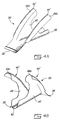
Fig. 4a is a front isometric view of an example of an individual lobe segment comprising a pair of partial outer lobes at circumferentially opposed ends thereof and a complete inner lobe therebetween; -
Fig. 4b is a rear isometric view of the individual lobe segment shown inFig. 4a ; -
Fig. 5 is an enlarged rear isometric view of an individual lobe segment mounted at an upstream end thereof to a support ring or flange adapted to be bolted to the turbine exhaust casing; and -
Fig. 6 is an enlarged side cross-section view illustrating one possible mounting arrangement of the upstream end of the lobe segments. -
Fig. 1 illustrates a turbofangas turbine engine 10 of a type preferably provided for use in subsonic flight, generally comprising in serial flow communication afan 12 through which ambient air is propelled, amultistage compressor 14 for pressurizing the air, acombustor 16 in which the compressed air is mixed with fuel and ignited for generating an annular stream of hot combustion gases, and aturbine section 18 for extracting energy from the combustion gases. - The
gas turbine engine 10 includes afirst casing 20 which encloses the turbo machinery of theengine 10, and a second,outer casing 22 extending outwardly of thefirst casing 20 such as to define anannular bypass passage 24 therebetween. The air propelled by thefan 12 is split into a first portion which flows around thefirst casing 20 within thebypass passage 24, and a second portion which flows through acore flow path 26 which is defined within thefirst casing 20 and allows the flow to circulate through themultistage compressor 14,combustor 16 andturbine section 18 as described above. - At the aft end of the
engine 10, anaxisymmetrical bullet 28 is centered on alongitudinal axis 30 of theengine 10 and defines an inner wall of thecore flow path 26 so that the combustion gases flow therearound. Amulti-lobe exhaust mixer 32 surrounds at least a portion of thebullet 28, themixer 32 acting as a rearmost portion of the outer wall defining thecore flow path 26 and a rearmost portion of the inner wall defining thebypass passage 24. The hot combustion gases from thecore flow path 26 and the cooler air from thebypass passage 24 are thus mixed together by themixer 32 at the exit thereof such as to produce an exhaust with a reduced temperature. - Referring to
Fig. 2 , themixer 32 has a generallyannular body 34 extending from anupstream end 36 along which the flows from thecore flow path 26 and from thebypass passage 24 are received to adownstream end 38 where the two flows meet and are mixed together. Theannular body 34 defines a plurality of circumferentially distributed lobes. The lobes include alternating inner andouter lobes outer lobes 44 extending radially outwardly into thebypass passage 24 and theinner lobes 42 extending radially inwardly into thecore flow path 26. Eachinner lobe 42 has atrough 42a forming an inner radial portion thereof. Likewise, eachouter lobe 44 has acrest 44a forming an outer radial portion thereof. Adjacent inner andouter lobes sidewalls 46 interconnectingadjacent troughs 42a andcrests 44a, one sidewall being positioned between eachtrough 42a and eachcrest 44a, a complete lobe being formed by a pair of sidewalls and a trough or a crest. - Referring now concurrently to
Figs. 3 ,4a and 4b , it can be appreciated that theannular body 34 is segmented into a plurality ofindividual lobe segments Figs. 4a and 4b ) at circumferentially opposed ends and a completeinner lobe 42 therebetween. However, it is understood eachlobe segment 50 could comprise one or more complete outer lobe bordered by two partial inner lobes. It is also understood that eachlobe segment sidewall 46 and acrest 44a. - As shown in
Fig. 3 , thelobe segments 50 are connected together at thecrests 44a of the partial outer lobes 44'. Thecrests 44a of the partial outer lobes 44' ofadjacent lobe segments outer lobe 44 with the sidewalls of the complete lobe forming part ofdifferent lobe segments exhaust mixer 32 is subjected to vibrations. As illustrated in the enlarged views ofFig. 3 , the partial lobe 144' at a first circumferential end of a givenlobe segment 50b may extend radially outwardly over an adjoining partial lobe 244' of a firstadjacent lobe segment 50a while the partial lobe 344' at the opposed circumferential end of thelobe segment 50b extends radially inwardly underneath the adjoining partial lobe 444' of a secondadjacent lobe segment 50c. The radially inwardly and radially outwardly overlapping arrangement alternate all around the segmentedmulti-lobe exhaust mixer 32. - It is understood that if the lobe segments are configured to comprise at least one complete outer lobe bordered by two partial inner lobes then the above described overlapping and nesting relationships of the individual lobe segments would take place at the
troughs 42a instead of at thecrests 44a. - The nested crest or trough arrangement provides for a stable while flexible lobe assembly which is well suited for accommodating thermal stresses and vibrations. Also, the modularity of the
multi-lobe exhaust mixer 32 simplify the fabrication of the lobe structure, thereby providing more flexibility in the choice of material that can be used for manufacturing themixer 32. According to one embodiment, eachindividual lobe segment exhaust mixer 32 compared with conventional metal exhaust mixers. - The modularity also allows to individually replace the lobes, thereby reducing replacement and maintenance costs. The use of individual lobe segments also provides for variable pitch and lobe shapes around the
multi-lobe exhaust mixer 32. For instance, the lobes could have various curvatures to perform a tailored de-swirling function. - As shown in
Figs. 5 and 6 , theindividual lobe segments upstream end 36 to asupport ring 60 adapted to be bolted or otherwise secured to the turbine exhaust case (not shown) of theengine 10. Thesupport ring 60 may have a sheet metal spring loadedflange 62 upon which the individual lobe segments 50a, 50b, 50c, 50d ... rest, thereby providing a vibration damping function. Aseparate flange 64 may be bolted or otherwise detachably mounted to thesupport ring 60 to axially retain and clamp theindividual lobe segments support ring 60. A damping material, such as a resilient and high temperatureresistant tape 66 or rope seal, may also be wrapped around theupstream end 36 of theindividual lobe segments support ring 60 to increase radial damping. The resilient and high temperatureresistant tape 66 may consist of a ceramic fiber tape, such as the one commercialized under the trade mark CerMax™. - Other lobe supporting structures (not shown) could be provided as well. For instance, a second support or stiffener ring (not shown) could be provided at the
downstream end 38 of themulti-lobe exhaust mixer 32. - The above description is meant to be exemplary only, and one skilled in the art will recognize that changes may be made to the embodiments described without departing from the scope of the invention disclosed. Modifications which fall within the scope of the present invention will be apparent to those skilled in the art, in light of a review of this disclosure, and such modifications are intended to fall within the appended claims.
Claims (15)
- A multi-lobe exhaust mixer (32) for a gas turbine engine (10), the multi-lobe exhaust mixer (32) comprising: an annular body (34) having an array of circumferentially distributed alternating inner and outer lobes (42, 44), the inner lobes (42) including troughs forming an inner radial portion thereof and the outer lobes (44) including crests forming an outer radial portion thereof, the annular body (34) being segmented into a plurality of individual lobe segments (50a, 50b, 50c, 50d...), and wherein the individual lobe segments (50a, 50b, 50c, 50d...) overlap at the crests or the troughs.
- The multi-lobe exhaust mixer (32) as defined in claim 1, wherein each of the individual lobe segments (50a, 50b, 50c, 50d...) has partial lobes (44') at circumferentially opposed ends and at least one complete lobe (42) therebetween, and wherein the partial lobes (44') of circumferentially adjacent lobe segments (50a, 50b, 50c, 50d...) are nested into each other.
- The multi-lobe exhaust mixer (32) defined in claim 2, wherein the inner or outer lobe (42, 44) formed at a junction of circumferentially adjacent first and second individual lobe segments (50a, 50b) has a first sidewall which is part of the first lobe segment (50a) and a second sidewall which is part of the second lobe segment (50b).
- The multi-lobe exhaust mixer (32) defined in claim 2 or 3, wherein the individual lobe segments comprise an intermediate lobe segment disposed between first and second adjacent lobe segments, and wherein the partial lobes of the intermediate lobe segment respectively extend radially outwardly over and radially inwardly under the first and second adjacent lobe segments.
- The multi-lobe exhaust mixer (32) defined in any preceding claim, wherein the individual lobe segments (50a, 50b, 50c, 50d...) are made of a ceramic matrix composite (CMC) material.
- The multi-lobe exhaust mixer (32) defined in any preceding claim, wherein the individual lobe segments (50a, 50b, 50c, 50d...) are mounted at an upstream end thereof to a support ring (60), and wherein the individual lobe segments (50a, 50b, 50c, 50d...) are preferably spring loaded on the support ring (60).
- The multi-lobe exhaust mixer (32) defined in claim 6, wherein the support ring (60) has a sheet metal spring loaded flange (62) upon which the individual lobe segments (50a, 50b, 50c, 50d...) rest, and wherein a separate flange (64) detachably mounted to support ring (60) axially retain and clamp the individual lobe segments (50a, 50b, 50c, 50d...) on the support ring (60)
- The multi-lobe exhaust mixer (32) defined in claim 7, wherein a damping material is wrapped around the upstream end of the individual lobe segments (50a, 50b, 50c, 50d...) on the support ring (60) and wherein the separate flange (64) preferably extends over the damping material, wherein the damping material is most preferably a ceramic fiber tape (66).
- A multi-lobe exhaust mixer (32) for a gas turbine engine (10), the multi-lobe exhaust mixer comprising: an annular body (34) composed of a plurality of circumferentially adjacent lobe segments (50a, 50b, 50c, 50d...), each lobe segment having partial lobes (44') at circumferentially opposed ends thereof and at least one complete lobe (42) therebetween, the partial lobes (44') of the circumferentially adjacent lobe segments (50a, 50b, 50c, 50d...) combining to conjointly form complete lobes at the junction between the circumferentially adjacent lobe segments (50a, 50b, 50c, 50d...).
- The multi-lobe exhaust mixer (32) defined in claim 9, wherein the partial lobes (44') of the circumferentially adjacent lobe segments (50a, 50b, 50c, 50d...) overlap each other, and wherein the partial lobes (44') preferably overlap at a crest or a trough.
- The multi-lobe exhaust mixer defined in claim 10, wherein the partial lobes (44') of circumferentially adjacent lobe segments (50a, 50b, 50c, 50d...) nest within each other.
- A multi-lobe exhaust mixer (32) for a gas turbine engine (10) of the type having an annular core flow passage for channelling a high temperature core flow along an axis of the engine, and a bypass passage (24) extending concentrically about the core flow passage for axially channelling bypass air; the multi-lobe exhaust mixer (32) comprising: an annular body (34) having an array of circumferentially distributed alternating inner and outer lobes (42, 44), the outer lobes (44) configured to protrude radially outwardly into the bypass passage (24) and the inner lobes (42) configured to protrude radially inwardly into the core flow passage, the annular body (34) being composed of a plurality of individual lobe segments (50a, 50b, 50c, 50d...) which alternately radially outwardly and radially inwardly overlap each other around the annular body (34).
- The multi-lobe exhaust mixer (32) defined in claim 12, wherein the inner lobes (42) include troughs forming an inner radial portion thereof and the outer lobes(44) include crests forming an outer radial portion thereof, and wherein circumferentially adjacent lobe segments (50a, 50b, 50c, 50d...) overlap each other at the crests or the troughs.
- The multi-lobe exhaust mixer (32) defined in claim 13, wherein each of the individual lobe segments (50a, 50b, 50c, 50d...) has partial lobes (44') at circumferentially opposed ends and at least one complete lobe therebetween, and wherein the partial lobes (44') of circumferentially adjacent lobe segments (50a, 50b, 50c, 50d...) are nested into each other.
- The multi-lobe exhaust mixer (32) defined in claim 12, 13 or 14, wherein the individual lobe segments (50a, 50b, 50c, 50d...) comprise an intermediate lobe (50b) segment disposed between first and second adjacent lobe segments (50a, 50c), and wherein the partial lobes (44') of the intermediate lobe segment (50b) respectively extend radially outwardly over and radially inwardly under the first and second adjacent lobe segments (50a, 50c), and wherein the individual lobe segments (50a, 50b, 50c, 50d...) are preferably clamped at an upstream end thereof to a support ring (60).
Applications Claiming Priority (1)
| Application Number | Priority Date | Filing Date | Title |
|---|---|---|---|
| US14/750,094 US10082043B2 (en) | 2015-06-25 | 2015-06-25 | Segmented multi-lobe mixer |
Publications (1)
| Publication Number | Publication Date |
|---|---|
| EP3109450A1 true EP3109450A1 (en) | 2016-12-28 |
Family
ID=56235695
Family Applications (1)
| Application Number | Title | Priority Date | Filing Date |
|---|---|---|---|
| EP16176115.0A Withdrawn EP3109450A1 (en) | 2015-06-25 | 2016-06-24 | Segmented multi-lobe mixer |
Country Status (3)
| Country | Link |
|---|---|
| US (1) | US10082043B2 (en) |
| EP (1) | EP3109450A1 (en) |
| CA (1) | CA2933350C (en) |
Cited By (1)
| Publication number | Priority date | Publication date | Assignee | Title |
|---|---|---|---|---|
| DE102016222583A1 (en) * | 2016-11-16 | 2018-05-17 | Rolls-Royce Deutschland Ltd & Co Kg | Mixer for an engine made of at least one composite material, manufacturing method and manufacturing device |
Families Citing this family (5)
| Publication number | Priority date | Publication date | Assignee | Title |
|---|---|---|---|---|
| FR3066714B1 (en) * | 2017-05-23 | 2021-01-08 | Safran Nacelles | TUBULAR PART WITH VOLUTES IN COMPOSITE AND FIBROUS STRUCTURE FOR DRAPING |
| US10801441B2 (en) | 2018-02-20 | 2020-10-13 | Pratt & Whitney Canada Corp. | Flow mixer stiffener ring segmented springs |
| US12181151B2 (en) | 2021-07-29 | 2024-12-31 | General Electric Company | Mixer vanes having a waveform profile |
| US12442532B2 (en) * | 2023-01-10 | 2025-10-14 | Pratt & Whitney Canada Corp. | Exhaust mixer with protrusions |
| US12565847B1 (en) * | 2024-10-25 | 2026-03-03 | Pratt & Whitney Canada Corp. | Aircraft engine having a scroll case and a turbine support case secured together |
Citations (4)
| Publication number | Priority date | Publication date | Assignee | Title |
|---|---|---|---|---|
| US5666802A (en) * | 1993-02-08 | 1997-09-16 | Lair; Jean-Pierre | Turbine engine equipped with thrust reverser |
| US20080115484A1 (en) * | 2004-09-29 | 2008-05-22 | Eric Conete | Mixer For Separate-Stream Nozzle |
| US8584356B2 (en) * | 2007-02-12 | 2013-11-19 | Snecma Propulsion Solide | Method of manufacturing a CMC flow mixer lobed structure for a gas turbine aeroengine |
| US20140075919A1 (en) * | 2012-09-17 | 2014-03-20 | Pratt & Whitney Canada Corp. | Tec mixer with variable thicknesses |
Family Cites Families (8)
| Publication number | Priority date | Publication date | Assignee | Title |
|---|---|---|---|---|
| US4240252A (en) * | 1978-01-19 | 1980-12-23 | General Electric Company | Acoustically-treated mixer for a mixed flow gas turbine engine |
| US4335801A (en) * | 1980-12-15 | 1982-06-22 | The Boeing Company | Noise suppressing nozzle |
| US7043898B2 (en) | 2003-06-23 | 2006-05-16 | Pratt & Whitney Canada Corp. | Combined exhaust duct and mixer for a gas turbine engine |
| FR2908465B1 (en) * | 2006-11-14 | 2011-12-23 | Snecma | VARIABLE FLOW MIXER WITH DEPLOYABLE LOBES IN FAN FOR DOUBLE FLOW TURBOREACTOR. |
| FR2914955B1 (en) | 2007-04-10 | 2009-07-10 | Snecma Propulsion Solide Sa | CMC MIXER WITH STRUCTURAL EXTERNAL COVERAGE |
| US8984890B2 (en) | 2011-10-31 | 2015-03-24 | General Electric Company | Turbofan engine mixer assembly |
| DE102013205911A1 (en) | 2013-04-04 | 2014-10-09 | MTU Aero Engines AG | Mixing device and turbofan engine with such a mixing device |
| US9745919B2 (en) * | 2014-07-30 | 2017-08-29 | Pratt & Whitney Canada Corp. | Gas turbine engine exhaust ejector/mixer |
-
2015
- 2015-06-25 US US14/750,094 patent/US10082043B2/en active Active
-
2016
- 2016-06-15 CA CA2933350A patent/CA2933350C/en active Active
- 2016-06-24 EP EP16176115.0A patent/EP3109450A1/en not_active Withdrawn
Patent Citations (4)
| Publication number | Priority date | Publication date | Assignee | Title |
|---|---|---|---|---|
| US5666802A (en) * | 1993-02-08 | 1997-09-16 | Lair; Jean-Pierre | Turbine engine equipped with thrust reverser |
| US20080115484A1 (en) * | 2004-09-29 | 2008-05-22 | Eric Conete | Mixer For Separate-Stream Nozzle |
| US8584356B2 (en) * | 2007-02-12 | 2013-11-19 | Snecma Propulsion Solide | Method of manufacturing a CMC flow mixer lobed structure for a gas turbine aeroengine |
| US20140075919A1 (en) * | 2012-09-17 | 2014-03-20 | Pratt & Whitney Canada Corp. | Tec mixer with variable thicknesses |
Cited By (3)
| Publication number | Priority date | Publication date | Assignee | Title |
|---|---|---|---|---|
| DE102016222583A1 (en) * | 2016-11-16 | 2018-05-17 | Rolls-Royce Deutschland Ltd & Co Kg | Mixer for an engine made of at least one composite material, manufacturing method and manufacturing device |
| EP3324026A3 (en) * | 2016-11-16 | 2018-08-15 | Rolls-Royce Deutschland Ltd & Co KG | Mixer for an engine made from at least one composite material, manufacturing method and manufacturing apparatus |
| US10947927B2 (en) | 2016-11-16 | 2021-03-16 | Rolls-Royce Deutschland Ltd & Co Kg | Mixer for an engine manufactured from at least one composite material, manufacturing method and manufacturing device |
Also Published As
| Publication number | Publication date |
|---|---|
| CA2933350A1 (en) | 2016-12-25 |
| US10082043B2 (en) | 2018-09-25 |
| US20160376928A1 (en) | 2016-12-29 |
| CA2933350C (en) | 2023-08-15 |
Similar Documents
| Publication | Publication Date | Title |
|---|---|---|
| CA2933350C (en) | Segmented multi-lobe mixer | |
| US20140260283A1 (en) | Gas turbine engine exhaust mixer with aerodynamic struts | |
| EP2770190A2 (en) | Exhaust section for bypass gas turbine engines | |
| EP2546574A2 (en) | Ceramic matrix composite combustor vane ring assembly | |
| US10619596B2 (en) | Gas turbine engine exhaust ejector/mixer | |
| CN107120690B (en) | burner assembly | |
| CA2952704C (en) | Combustor assembly | |
| CA2940706C (en) | Gas turbine engine exhaust mixer with lobes cross-over offset | |
| EP3044441B1 (en) | Shielding pockets for case holes | |
| US11286882B2 (en) | Exhaust casing for a gas turbine engine | |
| US10801441B2 (en) | Flow mixer stiffener ring segmented springs | |
| EP3211310B1 (en) | Combustor assembly | |
| US20160333890A1 (en) | Gas turbine engine inner case with non-integral vanes | |
| EP3225784B1 (en) | Flowpath assembly for a gas turbine engine | |
| WO2015084450A2 (en) | Shielding pockets for case holes | |
| US20240229738A1 (en) | Aircraft engine exhaust mixer | |
| US20180149169A1 (en) | Support structure for radial inlet of gas turbine engine |
Legal Events
| Date | Code | Title | Description |
|---|---|---|---|
| PUAI | Public reference made under article 153(3) epc to a published international application that has entered the european phase |
Free format text: ORIGINAL CODE: 0009012 |
|
| STAA | Information on the status of an ep patent application or granted ep patent |
Free format text: STATUS: THE APPLICATION HAS BEEN PUBLISHED |
|
| AK | Designated contracting states |
Kind code of ref document: A1 Designated state(s): AL AT BE BG CH CY CZ DE DK EE ES FI FR GB GR HR HU IE IS IT LI LT LU LV MC MK MT NL NO PL PT RO RS SE SI SK SM TR |
|
| AX | Request for extension of the european patent |
Extension state: BA ME |
|
| STAA | Information on the status of an ep patent application or granted ep patent |
Free format text: STATUS: REQUEST FOR EXAMINATION WAS MADE |
|
| 17P | Request for examination filed |
Effective date: 20170628 |
|
| RBV | Designated contracting states (corrected) |
Designated state(s): AL AT BE BG CH CY CZ DE DK EE ES FI FR GB GR HR HU IE IS IT LI LT LU LV MC MK MT NL NO PL PT RO RS SE SI SK SM TR |
|
| STAA | Information on the status of an ep patent application or granted ep patent |
Free format text: STATUS: EXAMINATION IS IN PROGRESS |
|
| 17Q | First examination report despatched |
Effective date: 20180508 |
|
| STAA | Information on the status of an ep patent application or granted ep patent |
Free format text: STATUS: THE APPLICATION IS DEEMED TO BE WITHDRAWN |
|
| 18D | Application deemed to be withdrawn |
Effective date: 20200603 |