EP3109052A1 - Liquid discharging apparatus - Google Patents
Liquid discharging apparatus Download PDFInfo
- Publication number
- EP3109052A1 EP3109052A1 EP16161705.5A EP16161705A EP3109052A1 EP 3109052 A1 EP3109052 A1 EP 3109052A1 EP 16161705 A EP16161705 A EP 16161705A EP 3109052 A1 EP3109052 A1 EP 3109052A1
- Authority
- EP
- European Patent Office
- Prior art keywords
- intersecting direction
- medium
- liquid
- scan sensor
- discharging
- Prior art date
- Legal status (The legal status is an assumption and is not a legal conclusion. Google has not performed a legal analysis and makes no representation as to the accuracy of the status listed.)
- Granted
Links
Images

Classifications
-
- B—PERFORMING OPERATIONS; TRANSPORTING
- B41—PRINTING; LINING MACHINES; TYPEWRITERS; STAMPS
- B41J—TYPEWRITERS; SELECTIVE PRINTING MECHANISMS, i.e. MECHANISMS PRINTING OTHERWISE THAN FROM A FORME; CORRECTION OF TYPOGRAPHICAL ERRORS
- B41J11/00—Devices or arrangements of selective printing mechanisms, e.g. ink-jet printers or thermal printers, for supporting or handling copy material in sheet or web form
- B41J11/0095—Detecting means for copy material, e.g. for detecting or sensing presence of copy material or its leading or trailing end
-
- B—PERFORMING OPERATIONS; TRANSPORTING
- B41—PRINTING; LINING MACHINES; TYPEWRITERS; STAMPS
- B41J—TYPEWRITERS; SELECTIVE PRINTING MECHANISMS, i.e. MECHANISMS PRINTING OTHERWISE THAN FROM A FORME; CORRECTION OF TYPOGRAPHICAL ERRORS
- B41J11/00—Devices or arrangements of selective printing mechanisms, e.g. ink-jet printers or thermal printers, for supporting or handling copy material in sheet or web form
- B41J11/008—Controlling printhead for accurately positioning print image on printing material, e.g. with the intention to control the width of margins
-
- B—PERFORMING OPERATIONS; TRANSPORTING
- B41—PRINTING; LINING MACHINES; TYPEWRITERS; STAMPS
- B41J—TYPEWRITERS; SELECTIVE PRINTING MECHANISMS, i.e. MECHANISMS PRINTING OTHERWISE THAN FROM A FORME; CORRECTION OF TYPOGRAPHICAL ERRORS
- B41J11/00—Devices or arrangements of selective printing mechanisms, e.g. ink-jet printers or thermal printers, for supporting or handling copy material in sheet or web form
- B41J11/0025—Handling copy materials differing in width
- B41J11/003—Paper-size detection, i.e. automatic detection of the length and/or width of copy material
-
- B—PERFORMING OPERATIONS; TRANSPORTING
- B41—PRINTING; LINING MACHINES; TYPEWRITERS; STAMPS
- B41J—TYPEWRITERS; SELECTIVE PRINTING MECHANISMS, i.e. MECHANISMS PRINTING OTHERWISE THAN FROM A FORME; CORRECTION OF TYPOGRAPHICAL ERRORS
- B41J11/00—Devices or arrangements of selective printing mechanisms, e.g. ink-jet printers or thermal printers, for supporting or handling copy material in sheet or web form
- B41J11/007—Conveyor belts or like feeding devices
-
- B—PERFORMING OPERATIONS; TRANSPORTING
- B41—PRINTING; LINING MACHINES; TYPEWRITERS; STAMPS
- B41J—TYPEWRITERS; SELECTIVE PRINTING MECHANISMS, i.e. MECHANISMS PRINTING OTHERWISE THAN FROM A FORME; CORRECTION OF TYPOGRAPHICAL ERRORS
- B41J15/00—Devices or arrangements of selective printing mechanisms, e.g. ink-jet printers or thermal printers, specially adapted for supporting or handling copy material in continuous form, e.g. webs
- B41J15/04—Supporting, feeding, or guiding devices; Mountings for web rolls or spindles
-
- B—PERFORMING OPERATIONS; TRANSPORTING
- B41—PRINTING; LINING MACHINES; TYPEWRITERS; STAMPS
- B41J—TYPEWRITERS; SELECTIVE PRINTING MECHANISMS, i.e. MECHANISMS PRINTING OTHERWISE THAN FROM A FORME; CORRECTION OF TYPOGRAPHICAL ERRORS
- B41J2/00—Typewriters or selective printing mechanisms characterised by the printing or marking process for which they are designed
- B41J2/005—Typewriters or selective printing mechanisms characterised by the printing or marking process for which they are designed characterised by bringing liquid or particles selectively into contact with a printing material
- B41J2/01—Ink jet
- B41J2/135—Nozzles
- B41J2/165—Prevention or detection of nozzle clogging, e.g. cleaning, capping or moistening for nozzles
- B41J2/16585—Prevention or detection of nozzle clogging, e.g. cleaning, capping or moistening for nozzles for paper-width or non-reciprocating print heads
- B41J2/16588—Print heads movable towards the cleaning unit
-
- B—PERFORMING OPERATIONS; TRANSPORTING
- B41—PRINTING; LINING MACHINES; TYPEWRITERS; STAMPS
- B41J—TYPEWRITERS; SELECTIVE PRINTING MECHANISMS, i.e. MECHANISMS PRINTING OTHERWISE THAN FROM A FORME; CORRECTION OF TYPOGRAPHICAL ERRORS
- B41J2/00—Typewriters or selective printing mechanisms characterised by the printing or marking process for which they are designed
- B41J2/005—Typewriters or selective printing mechanisms characterised by the printing or marking process for which they are designed characterised by bringing liquid or particles selectively into contact with a printing material
- B41J2/01—Ink jet
- B41J2/21—Ink jet for multi-colour printing
- B41J2/2132—Print quality control characterised by dot disposition, e.g. for reducing white stripes or banding
- B41J2/2146—Print quality control characterised by dot disposition, e.g. for reducing white stripes or banding for line print heads
-
- B—PERFORMING OPERATIONS; TRANSPORTING
- B41—PRINTING; LINING MACHINES; TYPEWRITERS; STAMPS
- B41J—TYPEWRITERS; SELECTIVE PRINTING MECHANISMS, i.e. MECHANISMS PRINTING OTHERWISE THAN FROM A FORME; CORRECTION OF TYPOGRAPHICAL ERRORS
- B41J29/00—Details of, or accessories for, typewriters or selective printing mechanisms not otherwise provided for
- B41J29/38—Drives, motors, controls or automatic cut-off devices for the entire printing mechanism
- B41J29/393—Devices for controlling or analysing the entire machine ; Controlling or analysing mechanical parameters involving printing of test patterns
-
- B—PERFORMING OPERATIONS; TRANSPORTING
- B41—PRINTING; LINING MACHINES; TYPEWRITERS; STAMPS
- B41J—TYPEWRITERS; SELECTIVE PRINTING MECHANISMS, i.e. MECHANISMS PRINTING OTHERWISE THAN FROM A FORME; CORRECTION OF TYPOGRAPHICAL ERRORS
- B41J2/00—Typewriters or selective printing mechanisms characterised by the printing or marking process for which they are designed
- B41J2/005—Typewriters or selective printing mechanisms characterised by the printing or marking process for which they are designed characterised by bringing liquid or particles selectively into contact with a printing material
- B41J2/01—Ink jet
- B41J2/135—Nozzles
- B41J2/165—Prevention or detection of nozzle clogging, e.g. cleaning, capping or moistening for nozzles
- B41J2/16505—Caps, spittoons or covers for cleaning or preventing drying out
- B41J2/16508—Caps, spittoons or covers for cleaning or preventing drying out connected with the printer frame
-
- B—PERFORMING OPERATIONS; TRANSPORTING
- B41—PRINTING; LINING MACHINES; TYPEWRITERS; STAMPS
- B41J—TYPEWRITERS; SELECTIVE PRINTING MECHANISMS, i.e. MECHANISMS PRINTING OTHERWISE THAN FROM A FORME; CORRECTION OF TYPOGRAPHICAL ERRORS
- B41J2/00—Typewriters or selective printing mechanisms characterised by the printing or marking process for which they are designed
- B41J2/005—Typewriters or selective printing mechanisms characterised by the printing or marking process for which they are designed characterised by bringing liquid or particles selectively into contact with a printing material
- B41J2/01—Ink jet
- B41J2/135—Nozzles
- B41J2/165—Prevention or detection of nozzle clogging, e.g. cleaning, capping or moistening for nozzles
- B41J2/16517—Cleaning of print head nozzles
- B41J2/16535—Cleaning of print head nozzles using wiping constructions
Definitions
- the present invention relates to a liquid discharging apparatus.
- a liquid discharging apparatus which includes a transport section for a medium, and a line head extending in a direction intersecting a direction of transporting the medium.
- a liquid discharging apparatus in a case in which a position of a transported medium is deviated from an original position where the medium is intended to be transported, an image may not be capable of being formed on a desired position of the medium. Therefore, for example, JP-A-2011-126204 discloses, an edge sensor, which is capable of detecting an end portion of a medium in a direction intersecting the direction of transporting the medium, and a recording apparatus (liquid discharging apparatus), which is capable of moving a head unit based on a detection result of the edge sensor.
- JP-A-2011-126204 is capable of controlling formation of an image on a desired position of the medium.
- an image may not be formed on a desired position of the medium in a case in which the medium is transported while being so deviated from the original position as greatly as being deviated from a position detectable by the edge sensor.
- An advantage of some aspects of the invention is that a discharging position of liquid with respect to a position of a medium by a line head can be accurately arranged.
- a liquid discharging apparatus includes a transport section for a medium, a line head in which nozzles discharging liquid in an intersecting direction that intersects a direction of transporting the medium are arrayed, a scan sensor that is moved in the intersecting direction and is capable of detecting an end portion of the medium in the intersecting direction, and a controller that controls movement of the scan sensor in the intersecting direction, and controls discharging of the liquid based on a detection result of the scan sensor.
- the controller may select nozzles to be used from the nozzles based on the detection result of the scan sensor.
- the line head may be configured to have a plurality of head units arranged in the intersecting direction, each head unit including the nozzles are arrayed in the intersecting direction, and the controller may select head units to be used from the head units based on the detection result of the scan sensor.
- the controller may output an error, in a case in which a length in the intersecting direction of the medium based on discharging data of the liquid is different from a length in the intersecting direction of the medium based on the detection result of the scan sensor.
- the controller may calculate a discharging width in the intersecting direction based on discharging data of the liquid and, in a case in which the calculated discharging width is longer than a length in the intersecting direction of the medium based on the detection result of the scan sensor, the controller may output an error.
- the controller controls discharging of the liquid based on the detection result.
- one end side in the intersecting direction may become a reference position for matching a position in the intersecting direction of the medium, and the controller may set a movement range in the intersecting direction of the scan sensor corresponding to a length of the medium in the intersecting direction based on discharging data of the liquid.
- the liquid discharging apparatus of an eighth aspect of the invention according to the first aspect may further include a meandering detection sensor that, when being disposed at a predetermined position, is capable of detecting whether or not the medium is transported in a meandering manner, by detecting the end portion at the predetermined position, and the controller may set the movement range in the intersecting direction of the scan sensor, based on the position of the meandering detection sensor.
- the scan sensor may be disposed at an upstream side further than the line head in the transport direction.
- the transport section may be a transporting belt causing the medium to be attached to and transported by the transporting belt.
- the liquid discharging apparatus of an eleventh aspect of the invention according to the eighth aspect may further include a cleaning section that is capable of cleaning the transporting belt and changing a cleaning region of the transporting belt in the intersecting direction, and the controller may set the cleaning region based on the detection result of the scan sensor.
- the discharging position of the liquid using the line head with respect to the position of the medium can be accurately arranged.
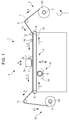
- Fig. 1 is a schematic side view of the recording apparatus 1 of the embodiment.
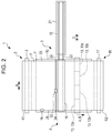
- Fig. 2 is a schematic plan view of the recording apparatus 1 of the embodiment.
- a part of configuration members are omitted in Fig. 2 .
- the recording apparatus 1 of the embodiment includes a feeding section 2 which is capable of feeding a roll R1 of a recording medium (medium) P for recording. Also, a transport mechanism 3 is included, which transports the recording medium P in the transport direction A by an adhesive belt 10 (endless belt) supporting the recording medium P on a supporting surface F to which an adhesive is attached. In addition, a recording mechanism 4 is included, which performs recording by discharging ink, which is an example of liquid, onto the recording medium P from nozzles N (refer to Figs. 4A to 5B ) of the line head 19 including the head unit 7 as a discharging section. Moreover, a cleaning mechanism 15 for the adhesive belt 10 is also included. Further, a winding mechanism 18 is included, which includes a winding shaft 17 winding the recording medium P.
- the feeding section 2 includes a rotating shaft 5, which serves as a setting position of the roll R1 of the recording medium P for recording, and is capable of feeding the recording medium P to the transport mechanism 3 through a driven roller 6 from the roll R1, which is set on the rotating shaft 5.
- the rotating shaft 5 is rotated in a rotating direction C.
- the transport mechanism 3 includes an adhesive belt 10 which mounts and transports the recording medium P fed from the feeding section 2, a driving roller 8 which drives the adhesive belt 10 in a direction E, and a driven roller 9.
- the recording medium P is pressed and attached onto the supporting surface F of the adhesive belt 10 by a pressing roller 12 so as to be mounted on the supporting surface.
- the driving roller 8 is rotated in the rotating direction C.
- the endless belt as a transporting belt is not limited to the adhesive belt.
- an electrostatic chuck endless belt may be used.
- a configuration in which the recording medium P is supported and transported by a moving support tray, or the like may be adopted, or a configuration in which the recording medium P is transported by a pair of rollers may be adopted.
- a so-called flatbed type recording apparatus may be used, which performs recording by fixing the recording medium P to a supporting section and moving the line head 19 with respect to the fixed recording medium.
- the recording mechanism 4 includes the line head 19 in which the nozzles N, which discharge liquid in the intersecting direction B intersecting the transport direction A of the recording medium P, are arranged (refer to Figs. 4A to 5B ).
- the line head 19 includes multiple head units 7 arranged in the intersecting direction B, in each of which the nozzles N are arranged in the intersecting direction B (refer to Figs. 4A to 5B ).
- the "line head” is a recording head, which is used to the recording apparatus in which a region of the nozzles N formed in the intersecting direction B intersecting the transport direction A of the recording medium P is provided to be capable of covering the entirety in the intersecting direction B of the recording medium P so that an image is formed by relatively moving the recording head or the recording medium P.
- a region of the nozzles N in the intersecting direction B of the line head 19 may not be capable of covering the entirety in the intersecting direction B of the entirety of the recording medium P supported by the recording apparatus 1.
- the line head 19 can be moved in the intersecting direction B along guide rails 22 and 23 between a recording position (position illustrated by solid line in Fig. 2 ) and a maintenance position (position illustrated by broken line in Fig. 2 ).
- a maintenance section 21 corresponding to the maintenance position of the line head 19 is provided, and the maintenance section 21 is capable of performing capping of the head unit 7, suctioning ink from the nozzles N of the head unit 7, wiping of the head unit 7 by a cap, a suctioning mechanism, a wiper, and the like (not illustrated) in a state in which the line head 19 is in the maintenance position.
- a meandering detection sensor 16 which is capable of detecting whether or not the recording medium P is meandered is provided at an upstream side of the line head 19 in the transport direction A.
- the meandering detection sensor 16 of the embodiment is configured so as to be capable of being moved to any position in the intersecting direction B manually by a user.
- the meandering detection sensor 16 detects whether or not the recording medium P is meandered and transported according to an absence/presence of the end portion 25 in a detection range of the meandering detection sensor 16 while transporting the recording medium P.
- a meandering control is capable of being executed by moving the roll R1 of the feeding section 2 in a direction of the rotating shaft 5, for example, based on a detection result using the meandering detection sensor 16.
- a scan sensor 20 which is capable of reciprocating (reciprocate-scanning) in the intersecting direction B along the guide rail 24 extending in the intersecting direction B, is provided downstream of the line head 19 in the transport direction A.
- the scan sensor 20 detects the end portion 25 in the intersecting direction B of the recording medium P by performing reciprocate-scanning in the intersecting direction B.
- the cleaning mechanism 15 for the adhesive belt 10 includes a cleaning brush 13 (refer to Fig. 2 ) in which a plurality of cleaning rollers 13a, 13b, 13c, and 13d are arranged in a rotating shaft direction (intersecting direction B), and a tray 14 containing detergent for cleaning the cleaning brush 13.
- the cleaning brush 13 of the embodiment is configured to have the cleaning rollers 13a, 13b, 13c, and 13d which are capable of being rotated in the rotating direction C and a reverse direction of the rotating direction C and arranged in the intersecting direction B.
- the cleaning rollers 13a, 13b, 13c, and 13d are individually moved in a direction D, and the cleaning rollers 13a, 13b, 13c, and 13d can be individually brought into contact with and separated from the adhesive belt 10.
- the winding mechanism 18 is a mechanism winding the recording medium P on which recording is performed, which is transported from the transport mechanism 3 through the driven roller 11, and is capable of winding as the roll R2 of the recording medium P by setting a paper tube, or the like for winding over the winding shaft 17 and winding the recording medium P.
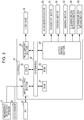
- Fig. 3 is a block diagram of the recording apparatus 1 of the embodiment.
- the controller 34 is provided with a CPU 35 which has in charge of controlling the entirety of the recording apparatus 1.
- the CPU 35 is connected to a ROM 26 in which various control programs, and the like executed by the CPU 35 are stored, and a RAM 27 which is capable of temporarily storing data, through a system bus 36.
- the CPU 35 is connected to the head driving section 28 for driving the line head 19, through the system bus 36.
- the CPU 35 is connected to a motor driving section 29 for driving a scan sensor motor 30, a transport motor 31, a feeding motor 32, a winding motor 33, a cleaning brush rotating motor 39, and a cleaning brush moving motor 40 through the system bus 36.
- the scan sensor motor 30 is a motor for reciprocating the scan sensor 20 in the intersecting direction B.
- the transport motor 31 is a motor for driving the driving roller 8.
- the feeding motor 32 is a rotation mechanism of the rotating shaft 5 and is a motor driving the rotating shaft 5 for feeding out the recording medium P to the transport mechanism 3.
- the winding motor 33 is a driving motor for rotating the winding shaft 17.
- the cleaning brush rotating motor 39 is a motor for rotating the cleaning brush 13 (cleaning rollers 13a, 13b, 13c, and 13d).
- the cleaning brush moving motor 40 is a motor which is a driving source for individually moving the cleaning rollers 13a, 13b, 13c, and 13d in the direction D.
- the CPU 35 is connected to the input/output section 37 through the system bus 36, and the input/output section 37 is connected to the meandering detection sensor 16, the scan sensor 20, and a PC 38 for receiving and transmitting data such as recording data and signals.
- the controller 23 controls movement of the scan sensor 20 in the intersecting direction B, and is capable of controlling discharging of the ink in the line head 19 based on a detection result of the scan sensor 20.
- the recording apparatus 1 of the embodiment includes the adhesive belt 10 which is the transport section of the recording medium P, and the line head 19 of which the nozzles N for discharging the ink in the intersecting direction B intersecting the transport direction A of the recording medium P are arranged.
- the recording apparatus 1 of the embodiment is capable of suppressing the deviation from a position where the medium can be detected for detecting transporting the recording medium P by making the scan region wide, even in a case where the recording medium P is transported by being greatly deviated from the original position where the medium is intended to be transported.
- the recording apparatus 1 of the embodiment is capable of accurately arranging the discharging position of the ink using the line head 19 with respect to the position of the recording medium P (position of medium).
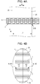
- Figs. 4A and 4B illustrate schematic view for describing the example of the control method of the recording apparatus 1 of the embodiment.
- Fig. 4A illustrates an arrangement of the head units 7 in the line head 19 and an example of a positional relationship between the line head 19 and the recording medium P in a state of being transported.
- Fig. 4B is an enlarged view of an IVB region of a part of Fig. 4A , and illustrates a positional relationship between the nozzles N of the head units 7 and the end portion 25 of the recording medium P in a state of being transported.
- Figs. 5A and 5B illustrate schematic views for describing another example of the control method in the recording apparatus 1 of the embodiment.
- Fig. 5A illustrates an arrangement of the head units 7 in the line head 19, and an example of a positional relationship between the line head 19 and the recording medium P in a state of being transported.
- Fig. 5B illustrates an enlarged view of a VB region of a part of Fig. 5A , and illustrates a positional relationship between the head units 7 and the end portion 25 of the recording medium P in a state of being transported.
- the controller 34 of the embodiment is capable of selecting the nozzles N1 to be used in the nozzles N based on the detection result of the scan sensor 20 (refer to Figs. 4A and 4B ). Specifically, based on the detection result of the scan sensor 20, the controller 34 determines whether or not the end portion 25 is positioned at which position of the line head 19 in the intersecting direction B. Also, as illustrated in Fig. 4B , the controller 34 sets the nozzles N at the position facing the recording medium P of an arrow R1 side further than the end portion 25 to the nozzles N1 to be used, and sets the nozzles N at the position not facing the recording medium P of an arrow R2 side further than the end portion 25 to the nozzles N2 not to be used.
- the recording apparatus 1 of the embodiment is capable of easily accurately arranging the discharging position of the ink using the line head 19 with respect to the position of the medium.
- the recording apparatus 1 of the embodiment is configured to have the head units 7 in which the nozzles N are arranged in the intersecting direction B, which are arranged multiple in the intersecting direction B; however, the controller 34 of the embodiment is capable of selecting the head units 7a which are used from the head units 7, based on the detection result of the scan sensor 20 (refer to Figs. 5A and 5B ). Specifically, based on the detection result of the scan sensor 20, the controller 34 determines whether or not the end portion 25 is positioned at which position of the line head 19 in the intersecting direction B. Also, as illustrated in Fig.
- the controller 34 sets the head units 7 of the arrow R1 side further than the end portion 25 and the head units 7 disposed at a position including the end portion 25 to the head units 7a being using, and sets the head units 7, which is not including the end portion 25, of the arrow R2 side further than the end portion 25 to the head units 7b not to be used. Accordingly, by selecting such a control method, that is, when the head units 7a to be used from the head units 7 are selected, the recording apparatus 1 of the embodiment is capable of easily accurately arranging the discharging position of the ink using the line head 19 with respect to the position of the medium.
- the controller 34 of the embodiment is capable of outputting an error, in a case in which a length in the intersecting direction B of the recording medium P based on recording data (data of ink discharging) is different from the length L1 (refer to Fig. 4A ) in the intersecting direction B of the recording medium P based on the detection result of the scan sensor 20.
- the recording apparatus 1 of the embodiment is capable of suppressing recording on the recording medium P different from the recording medium P to be assumed.
- the controller 34 of the embodiment is capable of outputting an error to the PC 38 serving as an alarm section. Accordingly, in a case in which the discharging width is longer than the length L1, it is possible to urge the user to modify the recording data so as to reduce the discharging width, or to change into the recording medium P having a wide width. Accordingly, the recording apparatus 1 of the embodiment is capable of suppressing the fact that an image formed using the ink discharged from the line head 19 is not fit into the recording medium P.
- the controller 34 of the embodiment is capable of suppressing discharging of the ink based on the detection result. Accordingly, at the time of the recording operation, the recording apparatus 1 of the embodiment is capable of accurately efficiently arranging the discharging position of the ink using the line head 19 with respect to the position of the medium by suppressing discharging of the ink in real time based on the detection result of the scan sensor 20.
- the controller 34 of the embodiment is capable of recognizing the position of the end portion 25, without detecting the end portion 25 in real time at the time of recording operation.
- the recording apparatus 1 of the embodiment has a configuration in which one end side (left side in Fig. 2 ) in the intersecting direction B becomes a reference position for arranging the position in the intersecting direction B of the recording medium P.
- the controller 34 is capable of setting a movement range in the intersecting direction B of the scan sensor 20, according to a length in the intersecting direction B of the recording medium P based on the recording data (ink discharging data). Accordingly, the recording apparatus 1 of the embodiment is capable of suppressing a movement in which the scan sensor 20 is moved to an unnecessary range (a range where the recording medium P absences) according to the length in the intersecting direction B of the recording medium P based on the recording data.
- the recording apparatus 1 of the embodiment includes the meandering detection sensor 16.
- the meandering detection sensor 16 of the embodiment is capable of detecting whether or not the recording medium P is meandered and transported by detecting the end portion 25 at the predetermined position.
- the controller 34 is capable of setting a movement range in the intersecting direction B of the scan sensor 20, based on a position of the meandering detection sensor 16 which is disposed by the user. Specifically, the controller 34 is capable of setting a movement range in the intersecting direction B of the scan sensor 20, so as not to include a range of the outside in the intersecting direction B further than the position of the meandering detection sensor 16 where the recording medium P is not exist. Accordingly, the recording apparatus 1 of the embodiment is capable of suppressing the fact that the scan sensor 20 is moved from the position of the meandering detection sensor 16 to an unnecessary range.
- the scan sensor 20 of the embodiment is disposed at an upstream side further than the line head 19 in the transport direction A. Accordingly, the recording apparatus 1 of the embodiment is capable of detecting a position of the recording medium P before the ink is discharged from the line head 19.
- the adhesive belt 10 which is the transport section of the embodiment, is a transporting belt which transports the recording medium P while being attached thereto.
- the transporting belt which transports the recording medium P while being attached thereto, once the recording medium P is attached thereto (supporting recording medium P), it is suppressed that the recording medium P is deviated from the transporting belt. After detecting a transporting deviation of the recording medium P from the original position where the medium is intended to be transported, the recording medium P is suppressed to be further deviated therefrom.
- the scan sensor 20 is provided at a plurality of positions, such as a upstream side and a downstream side further than the line head 19.
- the recording apparatus 1 of the embodiment includes the transporting belt which transports the recording medium P while being attached thereto, and thus the recording apparatus is capable of sufficiently accurately detecting the transporting deviation of the recording medium P from the original position where the medium is intended to be transported with only one scan sensor 20.
- the recording apparatus 1 of the embodiment includes the cleaning brush 13 as a cleaning section of the adhesive belt 10.
- the cleaning brush 13 changes a cleaning region of the adhesive belt 10 in the intersecting direction B.
- the controller 34 of the embodiment is capable of setting the cleaning region based on the detection result of the scan sensor 20. Specifically, based on the detection result of the scan sensor 20, the controller determines a region (a region is to be concerned of being contaminated due to the ink), where the ink is discharged, on the supporting surface F of the adhesive belt 10, and is capable of setting cleaning regions (selecting the cleaning rollers to be in contact with the adhesive belt 10 among the cleaning rollers 13a, 13b, 13c, and 13d) based on the determined result.
- the controller 34 allows the cleaning rollers, which are disposed at a position including a region in the inside further than the end portion 25 in the intersecting direction B, to be in contact with the adhesive belt 10, and allows the cleaning rollers, which are not disposed at a position including a region in the inside further than the end portion 25 in the intersecting direction B, not to be in contact with the adhesive belt 10.
- the transporting position of the recording medium P with respect to the adhesive belt 10 and the cleaning brush 13 is the positional relationship illustrated in Fig.
- all of the cleaning rollers 13a, 13b, 13c, and 13d are disposed at the position including the region in the inside further than the end portion 25 in the intersecting direction B, and thus all of them are in contact with the adhesive belt 10.
- the recording medium P having a width thereof narrower than the recording medium P for example, when the cleaning rollers 13c and 13d correspond to cleaning rollers, which are disposed at a position including a region of an inside further than the end portion 25, in a case in which the cleaning rollers 13a and 13b correspond to cleaning rollers, which are not disposed at the position including a region of an inside further than the end portion 25, the cleaning rollers 13c and 13d are in contact with the adhesive belt 10, and the cleaning rollers 13a and 13b are not in contact with the adhesive belt 10.
- the recording apparatus 1 of the embodiment is capable of suppressing inefficiency of cleaning the unnecessary region (region not contaminated with ink) in the adhesive belt 10.
- the invention is not limited to the embodiment described above, and can be variously changed within a range of the invention disclosed in Claims, further, it is needless to say that resultants thereof are also included in the range of the invention.
- the scan sensor 20 is stopped at the position of the end portion, and the recording medium P can be detected at the position where the sensor is stopped.
- the recording medium P is determined to be meandered, and thus a predetermined meandering control can be performed or an error can be detected.
- the meandering control can be performed with high accuracy, and the meandering control can be simply performed even in a case where the meandering detection sensor 16 is not provided as described above embodiment.
- the liquid discharging apparatus 1 of a first aspect of the invention includes the transport section 10 for the medium P, and the line head 19 in which the nozzles N discharging the liquid in intersecting direction B that intersects the transport direction A of the medium P are arrayed, the scan sensor 20 which is capable of detecting the end portion 25 of the medium P in the intersecting direction B by being moved in the intersecting direction B, and the controller 34 which controls a movement in the intersecting direction B of the scan sensor 20 and controls discharging of the liquid based on the detection result of the scan sensor 20.
- the scan sensor 20 which is capable of detecting the end portion 25 of the medium P in the intersecting direction B by being moved in the intersecting direction B, is included. Accordingly, even in a case where the medium P is transported by being greatly deviated from the original position where the medium is intended to be transported, deviation from the detectable position can be suppressed.
- the controller 34 controls a movement in the intersecting direction B of the scan sensor 20 and controls discharging of the liquid based on the detection result of the scan sensor 20. Accordingly, the discharging position of the liquid using the line head 19 with respect to the position of the medium can be accurately arranged.
- the controller 34 selects the nozzles N1 to be used from the nozzles N based on the detection result of the scan sensor 20.
- the controller 34 selects the nozzles N1 to be used from the nozzles N based on the detection result of the scan sensor 20. Accordingly, when the nozzles N1 to be used are selected from the nozzles N, simply, the discharging position of the liquid using the line head 19 with respect to the position of the medium can be accurately arranged.
- the line head 19 is configured to have the head units 7 which are arranged in the intersecting direction B and in each of which the nozzles N are arrayed in the intersecting direction B, and the controller 34 selects the head unit 7a to be used from the head units 7, based on the detection result of the scan sensor 20.
- the line head 19 is configured to have the head units 7 which are arranged in the intersecting direction B and in each of which the nozzles N are arranged in the intersecting direction B. Also, the controller 34 selects the head unit 7a to be used from the head units 7, based on the detection result of the scan sensor 20. Accordingly, when selecting the head unit 7a to be used from the head units 7, simply, the discharging position of the liquid using the line head 19 with respect to the position of the medium can be accurately arranged.
- the controller 34 outputs an error, in a case in which a length in the intersecting direction B of the medium P based on discharging data of the liquid is different from the length L1 in the intersecting direction B of the medium P based on the detection result of the scan sensor 20.
- the controller 34 outputs an error in a case in which a length in the intersecting direction B of the medium P based on the discharging data of the liquid is different from the length L1 in the intersecting direction B of the medium P based on the detection result of the scan sensor 20. Accordingly, in a case in which the width in the intersecting direction B of the medium P which is input to the controller 34 is different from the length L1, that is, a case in which the medium P being assumed is different from the medium P set in the liquid discharging apparatus 1, the user is urged to change the medium into an appropriate medium P, or the like. Therefore, discharging of the liquid onto the medium P which is different from the medium P being assumed can be suppressed.
- the controller 34 calculates a discharging width in the intersecting direction B based on discharging data of the liquid and, in a case in which the calculated discharging width is longer than the length L1 in the intersecting direction B of the medium P based on the detection result of the scan sensor 20, the controller outputs an error.
- the controller 34 calculates a discharging width in the intersecting direction B based on the discharging data of the liquid and, in a case in which the calculated discharging width is longer than the length L1 in the intersecting direction B of the medium P based on the detection result of the scan sensor 20, the controller outputs an error. Accordingly, it is possible to suppress an image formed by the liquid being formed outside of the medium P.
- the controller 34 controls discharging of the liquid based on the detection result.
- the controller 34 controls discharging of the liquid based on the detection result. Accordingly, at the time of the discharging operation of the liquid, when discharging of the liquid is controlled in real time based on the detection result of the scan sensor 20, efficiently, the discharging position of the liquid with respect to the position of the medium using the line head 19 can be accurately arranged.
- liquid discharging apparatus 1 of a seventh aspect of the invention in any one of the first aspect to the sixth aspect described above, one end side in the intersecting direction B becomes a reference position for matching the position in the intersecting direction B of the medium P, and the controller 34 sets a movement range in the intersecting direction B of the scan sensor 20 corresponding to a length of the medium P in the intersecting direction B based on discharging data of the liquid.
- one end side in the intersecting direction B is a reference position for matching the position in the intersecting direction B of the medium P
- the controller 34 sets the movement range in the intersecting direction B of the scan sensor 20 corresponding to the length in the intersecting direction B of the medium P based on the discharging data of the liquid. Accordingly, corresponding to the length in the intersecting direction B of the medium P based on the discharging data of the liquid, a movement of the scan sensor 20 to an unnecessary range can be suppressed.
- a meandering detection sensor 16 is further included, that, when being disposed at a predetermined position, is capable of detecting whether or not the medium P is meandered and transported by detecting the end portion 25 at the predetermined position, and the controller 34 sets the movement range in the intersecting direction B of the scan sensor 20 based on the position of the meandering detection sensor 16.
- the meandering detection sensor 16 is included, and the controller 34 sets the movement range in the intersecting direction B of the scan sensor 20 based on the position of the meandering detection sensor 16. Accordingly, a movement of the scan sensor 20 to an unnecessary range from the position of the meandering detection sensor 16 can be suppressed.
- the scan sensor 20 is disposed at an upstream side further than the line head 19 in the transport direction A.
- the scan sensor 20 is disposed at an upstream side further than the line head 19 in the transport direction A. Accordingly, the position of the medium P can be detected before discharging the liquid.
- the transport section 10 is a transporting belt which causes the medium P to be attached to and transported by the transporting belt.
- the transport section 10 is a transporting belt which transports the medium P while being attached thereto.
- the transporting belt transporting the medium P while being attached thereto, once the medium P is attached thereto (medium P is supported), the deviation of the medium P from the transporting belt can be suppressed, and thus the deviation of the medium P can be further suppressed, after detecting the transporting deviation of the medium P from the original position where the medium is intended to be transported. Accordingly, with only one scan sensor 20, the transporting deviation of the medium P from the original position where the medium is intended to be transported can be detected with a high accuracy.
- the cleaning section 13 is included, which is capable of cleaning the transporting belt and changing the cleaning region of the transporting belt in the intersecting direction B, and the controller 34 sets the cleaning region based on the detection result of the scan sensor 20.
- the cleaning section 13 which changes the cleaning region of the transporting belt in the intersecting direction B is included, and the controller 34 sets the cleaning region based on the detection result of the scan sensor 20. That is, the discharging region of the liquid is determined based on the detection result of the scan sensor 20, and the cleaning region can be set based on such a determined result. Accordingly, inefficiency of cleaning an unnecessary region of the transporting belt can be suppressed.
Landscapes
- Engineering & Computer Science (AREA)
- Quality & Reliability (AREA)
- Ink Jet (AREA)
- Particle Formation And Scattering Control In Inkjet Printers (AREA)
- Handling Of Sheets (AREA)
- Controlling Rewinding, Feeding, Winding, Or Abnormalities Of Webs (AREA)
Abstract
Description
- The present invention relates to a liquid discharging apparatus.
- In the related art, a liquid discharging apparatus, which includes a transport section for a medium, and a line head extending in a direction intersecting a direction of transporting the medium, is used. In such a liquid discharging apparatus, in a case in which a position of a transported medium is deviated from an original position where the medium is intended to be transported, an image may not be capable of being formed on a desired position of the medium. Therefore, for example,
JP-A-2011-126204 - The recording apparatus disclosed in
JP-A-2011-126204 - An advantage of some aspects of the invention is that a discharging position of liquid with respect to a position of a medium by a line head can be accurately arranged.
- According to a first aspect of the invention, a liquid discharging apparatus includes a transport section for a medium, a line head in which nozzles discharging liquid in an intersecting direction that intersects a direction of transporting the medium are arrayed, a scan sensor that is moved in the intersecting direction and is capable of detecting an end portion of the medium in the intersecting direction, and a controller that controls movement of the scan sensor in the intersecting direction, and controls discharging of the liquid based on a detection result of the scan sensor.
- In the liquid discharging apparatus of a second aspect of the invention according to the first aspect, the controller may select nozzles to be used from the nozzles based on the detection result of the scan sensor.
- In the liquid discharging apparatus of a third aspect of the invention according to the first aspect, the line head may be configured to have a plurality of head units arranged in the intersecting direction, each head unit including the nozzles are arrayed in the intersecting direction, and the controller may select head units to be used from the head units based on the detection result of the scan sensor.
- In the liquid discharging apparatus of a fourth aspect of the invention according to the first aspect, the controller may output an error, in a case in which a length in the intersecting direction of the medium based on discharging data of the liquid is different from a length in the intersecting direction of the medium based on the detection result of the scan sensor.
- In the liquid discharging apparatus of a fifth aspect of the invention according to the first aspect, the controller may calculate a discharging width in the intersecting direction based on discharging data of the liquid and, in a case in which the calculated discharging width is longer than a length in the intersecting direction of the medium based on the detection result of the scan sensor, the controller may output an error.
- In the liquid discharging apparatus of a sixth aspect of the invention according to the first aspect, at the time of the discharging operation of the liquid, when the scan sensor is reciprocated in the intersecting direction and the detection result of the scan sensor is input, the controller controls discharging of the liquid based on the detection result.
- In the liquid discharging apparatus of a seventh aspect of the invention according to the first aspect, one end side in the intersecting direction may become a reference position for matching a position in the intersecting direction of the medium, and the controller may set a movement range in the intersecting direction of the scan sensor corresponding to a length of the medium in the intersecting direction based on discharging data of the liquid.
- The liquid discharging apparatus of an eighth aspect of the invention according to the first aspect may further include a meandering detection sensor that, when being disposed at a predetermined position, is capable of detecting whether or not the medium is transported in a meandering manner, by detecting the end portion at the predetermined position, and the controller may set the movement range in the intersecting direction of the scan sensor, based on the position of the meandering detection sensor.
- In the liquid discharging apparatus of a ninth aspect of the invention according to the first aspect, the scan sensor may be disposed at an upstream side further than the line head in the transport direction.
- In the liquid discharging apparatus of a tenth aspect of the invention according to the first aspect, the transport section may be a transporting belt causing the medium to be attached to and transported by the transporting belt.
- The liquid discharging apparatus of an eleventh aspect of the invention according to the eighth aspect may further include a cleaning section that is capable of cleaning the transporting belt and changing a cleaning region of the transporting belt in the intersecting direction, and the controller may set the cleaning region based on the detection result of the scan sensor.
- According to the invention, the discharging position of the liquid using the line head with respect to the position of the medium can be accurately arranged.
- Embodiments of the invention will now be described by way of example only with reference to the accompanying drawings, wherein like numbers reference like elements.
-
Fig. 1 is a schematic side view illustrating a recording apparatus according to a first embodiment of the invention. -
Fig. 2 is a schematic plan view illustrating the recording apparatus according to the first embodiment of the invention. -
Fig. 3 is a block diagram illustrating the recording apparatus according to the first embodiment of the invention. -
Figs. 4A and 4B are schematic views for describing an example of a control method in the recording apparatus according to the first embodiment of the invention. -
Figs. 5A and 5B are schematic views for describing an example of a control method in the recording apparatus according to the first embodiment of the invention. - Hereinafter, a recording apparatus according to a first embodiment as a liquid discharging apparatus of the invention will be described with reference to attached drawings in detail.
- First, an outline of a
recording apparatus 1 according to the first embodiment of the invention will be described. -
Fig. 1 is a schematic side view of therecording apparatus 1 of the embodiment. In addition,Fig. 2 is a schematic plan view of therecording apparatus 1 of the embodiment. In order to easily describe main parts of therecording apparatus 1 of the embodiment, a part of configuration members are omitted inFig. 2 . - The
recording apparatus 1 of the embodiment includes a feeding section 2 which is capable of feeding a roll R1 of a recording medium (medium) P for recording. Also, atransport mechanism 3 is included, which transports the recording medium P in the transport direction A by an adhesive belt 10 (endless belt) supporting the recording medium P on a supporting surface F to which an adhesive is attached. In addition, arecording mechanism 4 is included, which performs recording by discharging ink, which is an example of liquid, onto the recording medium P from nozzles N (refer toFigs. 4A to 5B ) of theline head 19 including thehead unit 7 as a discharging section. Moreover, acleaning mechanism 15 for theadhesive belt 10 is also included. Further, awinding mechanism 18 is included, which includes awinding shaft 17 winding the recording medium P. - The feeding section 2 includes a
rotating shaft 5, which serves as a setting position of the roll R1 of the recording medium P for recording, and is capable of feeding the recording medium P to thetransport mechanism 3 through a drivenroller 6 from the roll R1, which is set on the rotatingshaft 5. When the recording medium P is fed to thetransport mechanism 3, the rotatingshaft 5 is rotated in a rotating direction C. - The
transport mechanism 3 includes anadhesive belt 10 which mounts and transports the recording medium P fed from the feeding section 2, adriving roller 8 which drives theadhesive belt 10 in a direction E, and a drivenroller 9. The recording medium P is pressed and attached onto the supporting surface F of theadhesive belt 10 by apressing roller 12 so as to be mounted on the supporting surface. Moreover, when the recording medium P is transported, thedriving roller 8 is rotated in the rotating direction C. - However, the endless belt as a transporting belt is not limited to the adhesive belt. For example, an electrostatic chuck endless belt may be used.
- In addition, a configuration in which the recording medium P is supported and transported by a moving support tray, or the like may be adopted, or a configuration in which the recording medium P is transported by a pair of rollers may be adopted. Further, a so-called flatbed type recording apparatus may be used, which performs recording by fixing the recording medium P to a supporting section and moving the
line head 19 with respect to the fixed recording medium. - The
recording mechanism 4 includes theline head 19 in which the nozzles N, which discharge liquid in the intersecting direction B intersecting the transport direction A of the recording medium P, are arranged (refer toFigs. 4A to 5B ). Theline head 19 includesmultiple head units 7 arranged in the intersecting direction B, in each of which the nozzles N are arranged in the intersecting direction B (refer toFigs. 4A to 5B ). - Here, the "line head" is a recording head, which is used to the recording apparatus in which a region of the nozzles N formed in the intersecting direction B intersecting the transport direction A of the recording medium P is provided to be capable of covering the entirety in the intersecting direction B of the recording medium P so that an image is formed by relatively moving the recording head or the recording medium P. A region of the nozzles N in the intersecting direction B of the
line head 19 may not be capable of covering the entirety in the intersecting direction B of the entirety of the recording medium P supported by therecording apparatus 1. - In addition, as illustrated in
Fig. 2 , theline head 19 can be moved in the intersecting direction B alongguide rails Fig. 2 ) and a maintenance position (position illustrated by broken line inFig. 2 ). In addition, as illustrated inFig. 2 , amaintenance section 21 corresponding to the maintenance position of theline head 19 is provided, and themaintenance section 21 is capable of performing capping of thehead unit 7, suctioning ink from the nozzles N of thehead unit 7, wiping of thehead unit 7 by a cap, a suctioning mechanism, a wiper, and the like (not illustrated) in a state in which theline head 19 is in the maintenance position. - In addition, a
meandering detection sensor 16 which is capable of detecting whether or not the recording medium P is meandered is provided at an upstream side of theline head 19 in the transport direction A. Themeandering detection sensor 16 of the embodiment is configured so as to be capable of being moved to any position in the intersecting direction B manually by a user. When the user disposes themeandering detection sensor 16 at a position where anend portion 25 of the recording medium P in the intersecting direction B can be detected, themeandering detection sensor 16 detects whether or not the recording medium P is meandered and transported according to an absence/presence of theend portion 25 in a detection range of themeandering detection sensor 16 while transporting the recording medium P. A meandering control is capable of being executed by moving the roll R1 of the feeding section 2 in a direction of the rotatingshaft 5, for example, based on a detection result using themeandering detection sensor 16. - In addition, downstream of the
line head 19 in the transport direction A, ascan sensor 20, which is capable of reciprocating (reciprocate-scanning) in the intersecting direction B along theguide rail 24 extending in the intersecting direction B, is provided. Thescan sensor 20 detects theend portion 25 in the intersecting direction B of the recording medium P by performing reciprocate-scanning in the intersecting direction B. - The
cleaning mechanism 15 for theadhesive belt 10 includes a cleaning brush 13 (refer toFig. 2 ) in which a plurality of cleaning rollers 13a, 13b, 13c, and 13d are arranged in a rotating shaft direction (intersecting direction B), and atray 14 containing detergent for cleaning the cleaningbrush 13. - As described above, the cleaning
brush 13 of the embodiment is configured to have the cleaning rollers 13a, 13b, 13c, and 13d which are capable of being rotated in the rotating direction C and a reverse direction of the rotating direction C and arranged in the intersecting direction B. In addition, the cleaning rollers 13a, 13b, 13c, and 13d are individually moved in a direction D, and the cleaning rollers 13a, 13b, 13c, and 13d can be individually brought into contact with and separated from theadhesive belt 10. - The winding
mechanism 18 is a mechanism winding the recording medium P on which recording is performed, which is transported from thetransport mechanism 3 through the drivenroller 11, and is capable of winding as the roll R2 of the recording medium P by setting a paper tube, or the like for winding over the windingshaft 17 and winding the recording medium P. - Next, an electric configuration of the
recording apparatus 1 of the embodiment will be described. -
Fig. 3 is a block diagram of therecording apparatus 1 of the embodiment. - The
controller 34 is provided with aCPU 35 which has in charge of controlling the entirety of therecording apparatus 1. TheCPU 35 is connected to aROM 26 in which various control programs, and the like executed by theCPU 35 are stored, and aRAM 27 which is capable of temporarily storing data, through asystem bus 36. - Also, the
CPU 35 is connected to thehead driving section 28 for driving theline head 19, through thesystem bus 36. - In addition, the
CPU 35 is connected to a motor driving section 29 for driving ascan sensor motor 30, atransport motor 31, a feedingmotor 32, a windingmotor 33, a cleaningbrush rotating motor 39, and a cleaningbrush moving motor 40 through thesystem bus 36. - Here, the
scan sensor motor 30 is a motor for reciprocating thescan sensor 20 in the intersecting direction B. In addition, thetransport motor 31 is a motor for driving the drivingroller 8. In addition, the feedingmotor 32 is a rotation mechanism of therotating shaft 5 and is a motor driving therotating shaft 5 for feeding out the recording medium P to thetransport mechanism 3. In addition, the windingmotor 33 is a driving motor for rotating the windingshaft 17. In addition, the cleaningbrush rotating motor 39 is a motor for rotating the cleaning brush 13 (cleaning rollers 13a, 13b, 13c, and 13d). In addition, the cleaningbrush moving motor 40 is a motor which is a driving source for individually moving the cleaning rollers 13a, 13b, 13c, and 13d in the direction D. - The
CPU 35 is connected to the input/output section 37 through thesystem bus 36, and the input/output section 37 is connected to the meanderingdetection sensor 16, thescan sensor 20, and aPC 38 for receiving and transmitting data such as recording data and signals. - Because of such a configuration, the
controller 23 controls movement of thescan sensor 20 in the intersecting direction B, and is capable of controlling discharging of the ink in theline head 19 based on a detection result of thescan sensor 20. - That is, the
recording apparatus 1 of the embodiment includes theadhesive belt 10 which is the transport section of the recording medium P, and theline head 19 of which the nozzles N for discharging the ink in the intersecting direction B intersecting the transport direction A of the recording medium P are arranged. In addition, thescan sensor 20, which is capable of detecting theend portion 25 of the recording medium P in the intersecting direction B by being moved in the intersecting direction B, is included, and thecontroller 34 controls a movement in the intersecting direction B of thescan sensor 20 and controls discharging of the ink based on the detection result of thescan sensor 20. - Accordingly, since the
scan sensor 20, which is capable of detecting theend portion 25 of the recording medium P in the intersecting direction B by being moved in the intersecting direction B, is included, therecording apparatus 1 of the embodiment is capable of suppressing the deviation from a position where the medium can be detected for detecting transporting the recording medium P by making the scan region wide, even in a case where the recording medium P is transported by being greatly deviated from the original position where the medium is intended to be transported. In addition, since thecontroller 34 controls the movement in the intersecting direction B of thescan sensor 20 and controls discharging of the ink based on the detection result of thescan sensor 20, therecording apparatus 1 of the embodiment is capable of accurately arranging the discharging position of the ink using theline head 19 with respect to the position of the recording medium P (position of medium). - Next, an example of a control method of the
recording apparatus 1 of the embodiment will be described. -
Figs. 4A and 4B illustrate schematic view for describing the example of the control method of therecording apparatus 1 of the embodiment. InFigs. 4A and 4B, Fig. 4A illustrates an arrangement of thehead units 7 in theline head 19 and an example of a positional relationship between theline head 19 and the recording medium P in a state of being transported. In addition,Fig. 4B is an enlarged view of an IVB region of a part ofFig. 4A , and illustrates a positional relationship between the nozzles N of thehead units 7 and theend portion 25 of the recording medium P in a state of being transported. -
Figs. 5A and 5B illustrate schematic views for describing another example of the control method in therecording apparatus 1 of the embodiment. InFigs. 5A and 5B, Fig. 5A illustrates an arrangement of thehead units 7 in theline head 19, and an example of a positional relationship between theline head 19 and the recording medium P in a state of being transported. In addition,Fig. 5B illustrates an enlarged view of a VB region of a part ofFig. 5A , and illustrates a positional relationship between thehead units 7 and theend portion 25 of the recording medium P in a state of being transported. - The
controller 34 of the embodiment is capable of selecting the nozzles N1 to be used in the nozzles N based on the detection result of the scan sensor 20 (refer toFigs. 4A and 4B ). Specifically, based on the detection result of thescan sensor 20, thecontroller 34 determines whether or not theend portion 25 is positioned at which position of theline head 19 in the intersecting direction B. Also, as illustrated inFig. 4B , thecontroller 34 sets the nozzles N at the position facing the recording medium P of an arrow R1 side further than theend portion 25 to the nozzles N1 to be used, and sets the nozzles N at the position not facing the recording medium P of an arrow R2 side further than theend portion 25 to the nozzles N2 not to be used. Accordingly, by selecting such a control method, that is, when the nozzles N1 to be used from the nozzles N are selected, therecording apparatus 1 of the embodiment is capable of easily accurately arranging the discharging position of the ink using theline head 19 with respect to the position of the medium. - In addition, the
recording apparatus 1 of the embodiment is configured to have thehead units 7 in which the nozzles N are arranged in the intersecting direction B, which are arranged multiple in the intersecting direction B; however, thecontroller 34 of the embodiment is capable of selecting the head units 7a which are used from thehead units 7, based on the detection result of the scan sensor 20 (refer toFigs. 5A and 5B ). Specifically, based on the detection result of thescan sensor 20, thecontroller 34 determines whether or not theend portion 25 is positioned at which position of theline head 19 in the intersecting direction B. Also, as illustrated inFig. 5B , thecontroller 34 sets thehead units 7 of the arrow R1 side further than theend portion 25 and thehead units 7 disposed at a position including theend portion 25 to the head units 7a being using, and sets thehead units 7, which is not including theend portion 25, of the arrow R2 side further than theend portion 25 to the head units 7b not to be used. Accordingly, by selecting such a control method, that is, when the head units 7a to be used from thehead units 7 are selected, therecording apparatus 1 of the embodiment is capable of easily accurately arranging the discharging position of the ink using theline head 19 with respect to the position of the medium. - In addition, the
controller 34 of the embodiment is capable of outputting an error, in a case in which a length in the intersecting direction B of the recording medium P based on recording data (data of ink discharging) is different from the length L1 (refer toFig. 4A ) in the intersecting direction B of the recording medium P based on the detection result of thescan sensor 20. Therefore, in a case in which a width of the medium in the intersecting direction B of the recording medium P, which is input to thecontroller 34 set when a user selects the recording medium P to be used by using thePC 38, or the like, is different from the length L1, that is, in a case in which the recording medium P to be assumed is different from the recording medium P set in therecording apparatus 1, it is possible to urge the user to change an appropriate recording medium P. Therefore, therecording apparatus 1 of the embodiment is capable of suppressing recording on the recording medium P different from the recording medium P to be assumed. - In addition, in a case in which a discharging width in the intersecting direction B is calculated based on the recording data (ink discharging data) and the calculated discharging width is longer than the length L1 (refer to
Fig. 4A ) in the intersecting direction B of the recording medium P based on the detection result of thescan sensor 20, thecontroller 34 of the embodiment is capable of outputting an error to thePC 38 serving as an alarm section. Accordingly, in a case in which the discharging width is longer than the length L1, it is possible to urge the user to modify the recording data so as to reduce the discharging width, or to change into the recording medium P having a wide width. Accordingly, therecording apparatus 1 of the embodiment is capable of suppressing the fact that an image formed using the ink discharged from theline head 19 is not fit into the recording medium P. - In addition, when the detection result of the
scan sensor 20 is input while reciprocating thescan sensor 20 in the intersecting direction B at the time of recording operation (ink discharging operation), thecontroller 34 of the embodiment is capable of suppressing discharging of the ink based on the detection result. Accordingly, at the time of the recording operation, therecording apparatus 1 of the embodiment is capable of accurately efficiently arranging the discharging position of the ink using theline head 19 with respect to the position of the medium by suppressing discharging of the ink in real time based on the detection result of thescan sensor 20. - Also, when the
scan sensor 20 is reciprocated in the intersecting direction B before the recording operation, thecontroller 34 of the embodiment is capable of recognizing the position of theend portion 25, without detecting theend portion 25 in real time at the time of recording operation. - In addition, the
recording apparatus 1 of the embodiment has a configuration in which one end side (left side inFig. 2 ) in the intersecting direction B becomes a reference position for arranging the position in the intersecting direction B of the recording medium P. Also, thecontroller 34 is capable of setting a movement range in the intersecting direction B of thescan sensor 20, according to a length in the intersecting direction B of the recording medium P based on the recording data (ink discharging data). Accordingly, therecording apparatus 1 of the embodiment is capable of suppressing a movement in which thescan sensor 20 is moved to an unnecessary range (a range where the recording medium P absences) according to the length in the intersecting direction B of the recording medium P based on the recording data. - In addition, as described above, the
recording apparatus 1 of the embodiment includes the meanderingdetection sensor 16. Here, when the user moves the meandering detection sensor in manual and disposes it at a predetermined position, the meanderingdetection sensor 16 of the embodiment is capable of detecting whether or not the recording medium P is meandered and transported by detecting theend portion 25 at the predetermined position. - The
controller 34 is capable of setting a movement range in the intersecting direction B of thescan sensor 20, based on a position of the meanderingdetection sensor 16 which is disposed by the user. Specifically, thecontroller 34 is capable of setting a movement range in the intersecting direction B of thescan sensor 20, so as not to include a range of the outside in the intersecting direction B further than the position of the meanderingdetection sensor 16 where the recording medium P is not exist. Accordingly, therecording apparatus 1 of the embodiment is capable of suppressing the fact that thescan sensor 20 is moved from the position of the meanderingdetection sensor 16 to an unnecessary range. - Also, as illustrated in
Fig. 1 andFig. 2 , thescan sensor 20 of the embodiment is disposed at an upstream side further than theline head 19 in the transport direction A. Accordingly, therecording apparatus 1 of the embodiment is capable of detecting a position of the recording medium P before the ink is discharged from theline head 19. - In addition, as illustrated in
Fig. 1 andFig. 2 , theadhesive belt 10, which is the transport section of the embodiment, is a transporting belt which transports the recording medium P while being attached thereto. - In the transporting belt which transports the recording medium P while being attached thereto, once the recording medium P is attached thereto (supporting recording medium P), it is suppressed that the recording medium P is deviated from the transporting belt. After detecting a transporting deviation of the recording medium P from the original position where the medium is intended to be transported, the recording medium P is suppressed to be further deviated therefrom.
- Here, after detecting a transporting deviation of the recording medium P from the original position where the medium is intended to be transported, and if there is a concern that the recording medium P is deviated, for example, it is preferable that the
scan sensor 20 is provided at a plurality of positions, such as a upstream side and a downstream side further than theline head 19. - However, the
recording apparatus 1 of the embodiment includes the transporting belt which transports the recording medium P while being attached thereto, and thus the recording apparatus is capable of sufficiently accurately detecting the transporting deviation of the recording medium P from the original position where the medium is intended to be transported with only onescan sensor 20. - In addition, as described above, the
recording apparatus 1 of the embodiment includes the cleaningbrush 13 as a cleaning section of theadhesive belt 10. The cleaningbrush 13 changes a cleaning region of theadhesive belt 10 in the intersecting direction B. - Also, the
controller 34 of the embodiment is capable of setting the cleaning region based on the detection result of thescan sensor 20. Specifically, based on the detection result of thescan sensor 20, the controller determines a region (a region is to be concerned of being contaminated due to the ink), where the ink is discharged, on the supporting surface F of theadhesive belt 10, and is capable of setting cleaning regions (selecting the cleaning rollers to be in contact with theadhesive belt 10 among the cleaning rollers 13a, 13b, 13c, and 13d) based on the determined result. In more detail, thecontroller 34 allows the cleaning rollers, which are disposed at a position including a region in the inside further than theend portion 25 in the intersecting direction B, to be in contact with theadhesive belt 10, and allows the cleaning rollers, which are not disposed at a position including a region in the inside further than theend portion 25 in the intersecting direction B, not to be in contact with theadhesive belt 10. For example, in a case in which the transporting position of the recording medium P with respect to theadhesive belt 10 and the cleaningbrush 13 is the positional relationship illustrated inFig. 2 , all of the cleaning rollers 13a, 13b, 13c, and 13d are disposed at the position including the region in the inside further than theend portion 25 in the intersecting direction B, and thus all of them are in contact with theadhesive belt 10. Meanwhile, when the recording medium P having a width thereof narrower than the recording medium P is used, for example, when the cleaning rollers 13c and 13d correspond to cleaning rollers, which are disposed at a position including a region of an inside further than theend portion 25, in a case in which the cleaning rollers 13a and 13b correspond to cleaning rollers, which are not disposed at the position including a region of an inside further than theend portion 25, the cleaning rollers 13c and 13d are in contact with theadhesive belt 10, and the cleaning rollers 13a and 13b are not in contact with theadhesive belt 10. - Accordingly, the
recording apparatus 1 of the embodiment is capable of suppressing inefficiency of cleaning the unnecessary region (region not contaminated with ink) in theadhesive belt 10. - Also, the invention is not limited to the embodiment described above, and can be variously changed within a range of the invention disclosed in Claims, further, it is needless to say that resultants thereof are also included in the range of the invention.
- For example, after detecting the position of the end portion of the recording medium P while moving the
scan sensor 20 like the above described embodiment, thescan sensor 20 is stopped at the position of the end portion, and the recording medium P can be detected at the position where the sensor is stopped. - In such a case, in a case in which the recording medium P is deviated from a detecting region where the
scan sensor 20 is stopped, or a case in which the position of the end portion is deviated from the position of the initially detected end portion further than a preset value, the recording medium P is determined to be meandered, and thus a predetermined meandering control can be performed or an error can be detected. When performing such a control, the meandering control can be performed with high accuracy, and the meandering control can be simply performed even in a case where the meanderingdetection sensor 16 is not provided as described above embodiment. - Hitherto, the invention has been described based on specific examples. Here, the outline of the invention will be described once more.
- According to the
liquid discharging apparatus 1 of a first aspect of the invention includes thetransport section 10 for the medium P, and theline head 19 in which the nozzles N discharging the liquid in intersecting direction B that intersects the transport direction A of the medium P are arrayed, thescan sensor 20 which is capable of detecting theend portion 25 of the medium P in the intersecting direction B by being moved in the intersecting direction B, and thecontroller 34 which controls a movement in the intersecting direction B of thescan sensor 20 and controls discharging of the liquid based on the detection result of thescan sensor 20. - According to the aspect, the
scan sensor 20 which is capable of detecting theend portion 25 of the medium P in the intersecting direction B by being moved in the intersecting direction B, is included. Accordingly, even in a case where the medium P is transported by being greatly deviated from the original position where the medium is intended to be transported, deviation from the detectable position can be suppressed. In addition, thecontroller 34 controls a movement in the intersecting direction B of thescan sensor 20 and controls discharging of the liquid based on the detection result of thescan sensor 20. Accordingly, the discharging position of the liquid using theline head 19 with respect to the position of the medium can be accurately arranged. - According to the
liquid discharging apparatus 1 of a second aspect of the invention, in the first aspect described above, thecontroller 34 selects the nozzles N1 to be used from the nozzles N based on the detection result of thescan sensor 20. - According to the aspect, the
controller 34 selects the nozzles N1 to be used from the nozzles N based on the detection result of thescan sensor 20. Accordingly, when the nozzles N1 to be used are selected from the nozzles N, simply, the discharging position of the liquid using theline head 19 with respect to the position of the medium can be accurately arranged. - According to the
liquid discharging apparatus 1 of a third aspect of the invention, in the first aspect described above, theline head 19 is configured to have thehead units 7 which are arranged in the intersecting direction B and in each of which the nozzles N are arrayed in the intersecting direction B, and thecontroller 34 selects the head unit 7a to be used from thehead units 7, based on the detection result of thescan sensor 20. - According to the aspect, the
line head 19 is configured to have thehead units 7 which are arranged in the intersecting direction B and in each of which the nozzles N are arranged in the intersecting direction B. Also, thecontroller 34 selects the head unit 7a to be used from thehead units 7, based on the detection result of thescan sensor 20. Accordingly, when selecting the head unit 7a to be used from thehead units 7, simply, the discharging position of the liquid using theline head 19 with respect to the position of the medium can be accurately arranged. - According to the
liquid discharging apparatus 1 of a fourth aspect of the invention, in any one of the first aspect to the third aspect described above, thecontroller 34 outputs an error, in a case in which a length in the intersecting direction B of the medium P based on discharging data of the liquid is different from the length L1 in the intersecting direction B of the medium P based on the detection result of thescan sensor 20. - According to the aspect, the
controller 34 outputs an error in a case in which a length in the intersecting direction B of the medium P based on the discharging data of the liquid is different from the length L1 in the intersecting direction B of the medium P based on the detection result of thescan sensor 20. Accordingly, in a case in which the width in the intersecting direction B of the medium P which is input to thecontroller 34 is different from the length L1, that is, a case in which the medium P being assumed is different from the medium P set in theliquid discharging apparatus 1, the user is urged to change the medium into an appropriate medium P, or the like. Therefore, discharging of the liquid onto the medium P which is different from the medium P being assumed can be suppressed. - According to the
liquid discharging apparatus 1 of an fifth aspect of the invention, in any one of the first aspect to the fourth aspect described above, thecontroller 34 calculates a discharging width in the intersecting direction B based on discharging data of the liquid and, in a case in which the calculated discharging width is longer than the length L1 in the intersecting direction B of the medium P based on the detection result of thescan sensor 20, the controller outputs an error. - According to the aspect, the
controller 34 calculates a discharging width in the intersecting direction B based on the discharging data of the liquid and, in a case in which the calculated discharging width is longer than the length L1 in the intersecting direction B of the medium P based on the detection result of thescan sensor 20, the controller outputs an error. Accordingly, it is possible to suppress an image formed by the liquid being formed outside of the medium P. - According to the
liquid discharging apparatus 1 of a sixth aspect of the invention, in any one of the first aspect to the fifth aspect described above, at the time of a discharging operation of the liquid, when thescan sensor 20 is reciprocated in the intersecting direction B and the detection result of thescan sensor 20 is input, thecontroller 34 controls discharging of the liquid based on the detection result. - According to the aspect, at the time of the discharging operation of the liquid, when the
scan sensor 20 is reciprocated in the intersecting direction B and the detection result of thescan sensor 20 is input, thecontroller 34 controls discharging of the liquid based on the detection result. Accordingly, at the time of the discharging operation of the liquid, when discharging of the liquid is controlled in real time based on the detection result of thescan sensor 20, efficiently, the discharging position of the liquid with respect to the position of the medium using theline head 19 can be accurately arranged. - According to the
liquid discharging apparatus 1 of a seventh aspect of the invention, in any one of the first aspect to the sixth aspect described above, one end side in the intersecting direction B becomes a reference position for matching the position in the intersecting direction B of the medium P, and thecontroller 34 sets a movement range in the intersecting direction B of thescan sensor 20 corresponding to a length of the medium P in the intersecting direction B based on discharging data of the liquid. - According to the aspect, one end side in the intersecting direction B is a reference position for matching the position in the intersecting direction B of the medium P, and the
controller 34 sets the movement range in the intersecting direction B of thescan sensor 20 corresponding to the length in the intersecting direction B of the medium P based on the discharging data of the liquid. Accordingly, corresponding to the length in the intersecting direction B of the medium P based on the discharging data of the liquid, a movement of thescan sensor 20 to an unnecessary range can be suppressed. - According to the
liquid discharging apparatus 1 of an eighth aspect of the invention, in any one of the first aspect to the sixth aspect described above, a meanderingdetection sensor 16 is further included, that, when being disposed at a predetermined position, is capable of detecting whether or not the medium P is meandered and transported by detecting theend portion 25 at the predetermined position, and thecontroller 34 sets the movement range in the intersecting direction B of thescan sensor 20 based on the position of the meanderingdetection sensor 16. - According to the aspect, the meandering
detection sensor 16 is included, and thecontroller 34 sets the movement range in the intersecting direction B of thescan sensor 20 based on the position of the meanderingdetection sensor 16. Accordingly, a movement of thescan sensor 20 to an unnecessary range from the position of the meanderingdetection sensor 16 can be suppressed. - According to the
liquid discharging apparatus 1 of a ninth aspect of the invention, in any one of the first aspect to the eighth aspect described above, thescan sensor 20 is disposed at an upstream side further than theline head 19 in the transport direction A. - According to the aspect, the
scan sensor 20 is disposed at an upstream side further than theline head 19 in the transport direction A. Accordingly, the position of the medium P can be detected before discharging the liquid. - According to the
liquid discharging apparatus 1 of a tenth aspect of the invention, in any one of the first aspect to the ninth aspect described above, thetransport section 10 is a transporting belt which causes the medium P to be attached to and transported by the transporting belt. - According to the aspect, the
transport section 10 is a transporting belt which transports the medium P while being attached thereto. In the transporting belt transporting the medium P while being attached thereto, once the medium P is attached thereto (medium P is supported), the deviation of the medium P from the transporting belt can be suppressed, and thus the deviation of the medium P can be further suppressed, after detecting the transporting deviation of the medium P from the original position where the medium is intended to be transported. Accordingly, with only onescan sensor 20, the transporting deviation of the medium P from the original position where the medium is intended to be transported can be detected with a high accuracy. - According to the
liquid discharging apparatus 1 of an eleventh aspect of the invention, in the tenth aspect described above, thecleaning section 13 is included, which is capable of cleaning the transporting belt and changing the cleaning region of the transporting belt in the intersecting direction B, and thecontroller 34 sets the cleaning region based on the detection result of thescan sensor 20. - According to the aspect, the
cleaning section 13 which changes the cleaning region of the transporting belt in the intersecting direction B is included, and thecontroller 34 sets the cleaning region based on the detection result of thescan sensor 20. That is, the discharging region of the liquid is determined based on the detection result of thescan sensor 20, and the cleaning region can be set based on such a determined result. Accordingly, inefficiency of cleaning an unnecessary region of the transporting belt can be suppressed.
Claims (11)
- A liquid discharging apparatus comprising:a transport section for a medium;a line head in which nozzles discharging liquid in an intersecting direction that intersects a direction of transporting the medium are arrayed;a scan sensor that is moved in the intersecting direction and is capable of detecting an end portion of the medium in the intersecting direction; anda controller that controls movement of the scan sensor in the intersecting direction, and controls discharging of the liquid based on a detection result of the scan sensor.
- The liquid discharging apparatus according to Claim 1,
wherein the controller selects nozzles to be used from the nozzles based on the detection result of the scan sensor. - The liquid discharging apparatus according to Claim 1,
wherein the line head is configured to have a plurality of head units arranged in the intersecting direction, each head unit including the nozzles arrayed in the intersecting direction and
wherein the controller selects head units to be used from the head units based on the detection result of the scan sensor. - The liquid discharging apparatus according to Claim 1,
wherein the controller outputs an error, in a case in which a length in the intersecting direction of the medium based on discharging data of the liquid is different from a length in the intersecting direction of the medium based on the detection result of the scan sensor. - The liquid discharging apparatus according to Claim 1,
wherein the controller calculates a discharging width in the intersecting direction based on discharging data of the liquid and in a case in which the calculated discharging width is longer than a length in the intersecting direction of the medium based on the detection result of the scan sensor, the controller outputs an error. - The liquid discharging apparatus according to Claim 1,
wherein, at the time of the discharging operation of the liquid, when the scan sensor is reciprocated in the intersecting direction and the detection result of the scan sensor is input, the controller controls discharging of the liquid based on the detection result. - The liquid discharging apparatus according to Claim 1,
wherein one end side in the intersecting direction is a reference position for matching a position in the intersecting direction of the medium and
wherein the controller sets a movement range in the intersecting direction of the scan sensor corresponding to a length of the medium in the intersecting direction based on discharging data of the liquid. - The liquid discharging apparatus according to Claim 1, further comprising:a meandering detection sensor that when being disposed at a predetermined position is capable of detecting whether or not the medium is transported in a meandering manner by detecting the end portion at the predetermined position,wherein the controller sets the movement range of the scan sensor in the intersecting direction, based on the position of the meandering detection sensor.
- The liquid discharging apparatus according to Claim 1,
wherein the scan sensor is disposed at an upstream side further than the line head in the transport direction. - The liquid discharging apparatus according to Claim 1,
wherein the transport section includes a transporting belt causing the medium to be attached to and transported by the transporting belt. - The liquid discharging apparatus according to Claim 10, further comprising:a cleaning section that is capable of cleaning the transporting belt and changing a cleaning region of the transporting belt in the intersecting direction,wherein the controller sets the cleaning region based on the detection result of the scan sensor.
Applications Claiming Priority (1)
| Application Number | Priority Date | Filing Date | Title |
|---|---|---|---|
| JP2015108554A JP6528944B2 (en) | 2015-05-28 | 2015-05-28 | Liquid discharge device |
Publications (2)
| Publication Number | Publication Date |
|---|---|
| EP3109052A1 true EP3109052A1 (en) | 2016-12-28 |
| EP3109052B1 EP3109052B1 (en) | 2020-02-12 |
Family
ID=55588138
Family Applications (1)
| Application Number | Title | Priority Date | Filing Date |
|---|---|---|---|
| EP16161705.5A Active EP3109052B1 (en) | 2015-05-28 | 2016-03-22 | Liquid discharging apparatus |
Country Status (3)
| Country | Link |
|---|---|
| EP (1) | EP3109052B1 (en) |
| JP (1) | JP6528944B2 (en) |
| CN (1) | CN106183452B (en) |
Cited By (3)
| Publication number | Priority date | Publication date | Assignee | Title |
|---|---|---|---|---|
| US11727234B2 (en) | 2019-09-13 | 2023-08-15 | Seiko Epson Corporation | Performance of printing based on detected end portions of medium |
| WO2024100167A1 (en) * | 2022-11-08 | 2024-05-16 | Dover Europe Sarl | Printing apparatus and printing method |
| WO2024100163A1 (en) * | 2022-11-08 | 2024-05-16 | Dover Europe Sarl | Printing apparatus and printing method |
Citations (2)
| Publication number | Priority date | Publication date | Assignee | Title |
|---|---|---|---|---|
| US20090092404A1 (en) * | 2007-10-05 | 2009-04-09 | Tashiro Kazuya | Image forming apparatus and image forming method |
| JP2011126204A (en) | 2009-12-18 | 2011-06-30 | Seiko Epson Corp | Recording position correcting device, and recording apparatus |
Family Cites Families (12)
| Publication number | Priority date | Publication date | Assignee | Title |
|---|---|---|---|---|
| JPS6280081A (en) * | 1985-10-02 | 1987-04-13 | Canon Inc | recording device |
| JP2001096874A (en) * | 1999-09-30 | 2001-04-10 | Fuji Photo Film Co Ltd | Method and apparatus for recording image |
| WO2004018218A1 (en) * | 2002-08-21 | 2004-03-04 | Seiko Epson Corporation | Printer, program, and printing method |
| JP4608847B2 (en) * | 2003-05-01 | 2011-01-12 | セイコーエプソン株式会社 | Liquid ejection apparatus, correction pattern, correction pattern forming method, and liquid ejection system |
| US20050062780A1 (en) * | 2003-09-18 | 2005-03-24 | Chee Chong Hin | Print mechanism utilizing an optical imaging sensor to sense the print medium |
| JP2005096135A (en) * | 2003-09-22 | 2005-04-14 | Fuji Photo Film Co Ltd | Carrying apparatus for recording medium and image forming apparatus |
| JP4306700B2 (en) * | 2006-07-13 | 2009-08-05 | セイコーエプソン株式会社 | Printing apparatus and printing method |
| JP5326418B2 (en) * | 2007-10-05 | 2013-10-30 | 株式会社リコー | Image forming apparatus and image forming method |
| JP5538835B2 (en) * | 2008-12-02 | 2014-07-02 | キヤノン株式会社 | Printing device |
| JP5803315B2 (en) * | 2011-06-17 | 2015-11-04 | セイコーエプソン株式会社 | Image recording apparatus and image recording method |
| US20150138292A1 (en) * | 2013-10-21 | 2015-05-21 | Mark Andy, Inc. | System for aligning a media web in a printing press |
| JP6269926B2 (en) * | 2013-10-22 | 2018-01-31 | セイコーエプソン株式会社 | Recording device |
-
2015
- 2015-05-28 JP JP2015108554A patent/JP6528944B2/en active Active
-
2016
- 2016-03-22 EP EP16161705.5A patent/EP3109052B1/en active Active
- 2016-03-23 CN CN201610168855.4A patent/CN106183452B/en active Active
Patent Citations (2)
| Publication number | Priority date | Publication date | Assignee | Title |
|---|---|---|---|---|
| US20090092404A1 (en) * | 2007-10-05 | 2009-04-09 | Tashiro Kazuya | Image forming apparatus and image forming method |
| JP2011126204A (en) | 2009-12-18 | 2011-06-30 | Seiko Epson Corp | Recording position correcting device, and recording apparatus |
Cited By (3)
| Publication number | Priority date | Publication date | Assignee | Title |
|---|---|---|---|---|
| US11727234B2 (en) | 2019-09-13 | 2023-08-15 | Seiko Epson Corporation | Performance of printing based on detected end portions of medium |
| WO2024100167A1 (en) * | 2022-11-08 | 2024-05-16 | Dover Europe Sarl | Printing apparatus and printing method |
| WO2024100163A1 (en) * | 2022-11-08 | 2024-05-16 | Dover Europe Sarl | Printing apparatus and printing method |
Also Published As
| Publication number | Publication date |
|---|---|
| EP3109052B1 (en) | 2020-02-12 |
| JP6528944B2 (en) | 2019-06-12 |
| CN106183452B (en) | 2019-03-01 |
| JP2016221752A (en) | 2016-12-28 |
| CN106183452A (en) | 2016-12-07 |
Similar Documents
| Publication | Publication Date | Title |
|---|---|---|
| US8783817B2 (en) | Recording device and recording method | |
| EP3109052A1 (en) | Liquid discharging apparatus | |
| CN102935766A (en) | Method of controlling a printing device, and a printing device | |
| EP3047977B1 (en) | Liquid ejecting apparatus and method of detection | |
| EP3109051A1 (en) | Liquid discharging apparatus | |
| EP3109053A1 (en) | Liquid discharging apparatus | |
| EP2923849B1 (en) | Recording apparatus and method for cleaning transport belt | |
| JP2011073841A (en) | Image forming device | |
| EP2754557A1 (en) | Recording apparatus and recording method | |
| JP6079683B2 (en) | Electronics | |
| EP2857335B1 (en) | Recording apparatus and recording method | |
| JP6646249B2 (en) | Liquid ejection device and transport amount adjustment method | |
| JP6558186B2 (en) | Velocity detection device and liquid ejection device | |
| JP5838698B2 (en) | Measuring device and electrical device | |
| JP2018052090A (en) | Inkjet recording device | |
| EP2921308B1 (en) | Recording apparatus and method for transporting recording medium | |
| US10960693B2 (en) | Image forming system | |
| JP5962390B2 (en) | Sheet conveying apparatus and image forming system | |
| JP6759727B2 (en) | Printing equipment, programs | |
| EP3549774A1 (en) | Recording apparatus | |
| JP2017081069A (en) | Liquid ejecting apparatus and method for controlling liquid ejecting apparatus | |
| JP2016137579A (en) | Printing device and printing control device | |
| CN104742522B (en) | Recording equipment | |
| JP2013193392A (en) | Image forming apparatus | |
| JP2017087474A (en) | Liquid ejecting apparatus and method for controlling liquid ejecting apparatus |
Legal Events
| Date | Code | Title | Description |
|---|---|---|---|
| PUAI | Public reference made under article 153(3) epc to a published international application that has entered the european phase |
Free format text: ORIGINAL CODE: 0009012 |
|
| STAA | Information on the status of an ep patent application or granted ep patent |
Free format text: STATUS: THE APPLICATION HAS BEEN PUBLISHED |
|
| AK | Designated contracting states |
Kind code of ref document: A1 Designated state(s): AL AT BE BG CH CY CZ DE DK EE ES FI FR GB GR HR HU IE IS IT LI LT LU LV MC MK MT NL NO PL PT RO RS SE SI SK SM TR |
|
| AX | Request for extension of the european patent |
Extension state: BA ME |
|
| STAA | Information on the status of an ep patent application or granted ep patent |
Free format text: STATUS: REQUEST FOR EXAMINATION WAS MADE |
|
| 17P | Request for examination filed |
Effective date: 20170518 |
|
| RBV | Designated contracting states (corrected) |
Designated state(s): AL AT BE BG CH CY CZ DE DK EE ES FI FR GB GR HR HU IE IS IT LI LT LU LV MC MK MT NL NO PL PT RO RS SE SI SK SM TR |
|
| STAA | Information on the status of an ep patent application or granted ep patent |
Free format text: STATUS: EXAMINATION IS IN PROGRESS |
|
| 17Q | First examination report despatched |
Effective date: 20190326 |
|
| REG | Reference to a national code |
Ref country code: DE Ref legal event code: R079 Ref document number: 602016029346 Country of ref document: DE Free format text: PREVIOUS MAIN CLASS: B41J0011000000 Ipc: B41J0002165000 |
|
| GRAP | Despatch of communication of intention to grant a patent |
Free format text: ORIGINAL CODE: EPIDOSNIGR1 |
|
| STAA | Information on the status of an ep patent application or granted ep patent |
Free format text: STATUS: GRANT OF PATENT IS INTENDED |
|
| RIC1 | Information provided on ipc code assigned before grant |
Ipc: B41J 2/21 20060101ALI20191101BHEP Ipc: B41J 2/165 20060101AFI20191101BHEP Ipc: B41J 15/04 20060101ALI20191101BHEP Ipc: B41J 11/00 20060101ALI20191101BHEP |
|
| INTG | Intention to grant announced |
Effective date: 20191118 |
|
| GRAS | Grant fee paid |
Free format text: ORIGINAL CODE: EPIDOSNIGR3 |
|
| GRAA | (expected) grant |
Free format text: ORIGINAL CODE: 0009210 |
|
| STAA | Information on the status of an ep patent application or granted ep patent |
Free format text: STATUS: THE PATENT HAS BEEN GRANTED |
|
| AK | Designated contracting states |
Kind code of ref document: B1 Designated state(s): AL AT BE BG CH CY CZ DE DK EE ES FI FR GB GR HR HU IE IS IT LI LT LU LV MC MK MT NL NO PL PT RO RS SE SI SK SM TR |
|
| REG | Reference to a national code |
Ref country code: GB Ref legal event code: FG4D |
|
| REG | Reference to a national code |
Ref country code: CH Ref legal event code: EP |
|
| REG | Reference to a national code |
Ref country code: AT Ref legal event code: REF Ref document number: 1231580 Country of ref document: AT Kind code of ref document: T Effective date: 20200215 |
|
| REG | Reference to a national code |
Ref country code: IE Ref legal event code: FG4D |
|
| REG | Reference to a national code |
Ref country code: DE Ref legal event code: R096 Ref document number: 602016029346 Country of ref document: DE |
|
| PG25 | Lapsed in a contracting state [announced via postgrant information from national office to epo] |
Ref country code: RS Free format text: LAPSE BECAUSE OF FAILURE TO SUBMIT A TRANSLATION OF THE DESCRIPTION OR TO PAY THE FEE WITHIN THE PRESCRIBED TIME-LIMIT Effective date: 20200212 Ref country code: FI Free format text: LAPSE BECAUSE OF FAILURE TO SUBMIT A TRANSLATION OF THE DESCRIPTION OR TO PAY THE FEE WITHIN THE PRESCRIBED TIME-LIMIT Effective date: 20200212 Ref country code: NO Free format text: LAPSE BECAUSE OF FAILURE TO SUBMIT A TRANSLATION OF THE DESCRIPTION OR TO PAY THE FEE WITHIN THE PRESCRIBED TIME-LIMIT Effective date: 20200512 |
|
| REG | Reference to a national code |
Ref country code: LT Ref legal event code: MG4D |
|
| REG | Reference to a national code |
Ref country code: NL Ref legal event code: MP Effective date: 20200212 |
|
| PG25 | Lapsed in a contracting state [announced via postgrant information from national office to epo] |
Ref country code: LV Free format text: LAPSE BECAUSE OF FAILURE TO SUBMIT A TRANSLATION OF THE DESCRIPTION OR TO PAY THE FEE WITHIN THE PRESCRIBED TIME-LIMIT Effective date: 20200212 Ref country code: SE Free format text: LAPSE BECAUSE OF FAILURE TO SUBMIT A TRANSLATION OF THE DESCRIPTION OR TO PAY THE FEE WITHIN THE PRESCRIBED TIME-LIMIT Effective date: 20200212 Ref country code: BG Free format text: LAPSE BECAUSE OF FAILURE TO SUBMIT A TRANSLATION OF THE DESCRIPTION OR TO PAY THE FEE WITHIN THE PRESCRIBED TIME-LIMIT Effective date: 20200512 Ref country code: IS Free format text: LAPSE BECAUSE OF FAILURE TO SUBMIT A TRANSLATION OF THE DESCRIPTION OR TO PAY THE FEE WITHIN THE PRESCRIBED TIME-LIMIT Effective date: 20200612 Ref country code: GR Free format text: LAPSE BECAUSE OF FAILURE TO SUBMIT A TRANSLATION OF THE DESCRIPTION OR TO PAY THE FEE WITHIN THE PRESCRIBED TIME-LIMIT Effective date: 20200513 Ref country code: HR Free format text: LAPSE BECAUSE OF FAILURE TO SUBMIT A TRANSLATION OF THE DESCRIPTION OR TO PAY THE FEE WITHIN THE PRESCRIBED TIME-LIMIT Effective date: 20200212 |
|
| PG25 | Lapsed in a contracting state [announced via postgrant information from national office to epo] |
Ref country code: NL Free format text: LAPSE BECAUSE OF FAILURE TO SUBMIT A TRANSLATION OF THE DESCRIPTION OR TO PAY THE FEE WITHIN THE PRESCRIBED TIME-LIMIT Effective date: 20200212 |
|
| PG25 | Lapsed in a contracting state [announced via postgrant information from national office to epo] |
Ref country code: SK Free format text: LAPSE BECAUSE OF FAILURE TO SUBMIT A TRANSLATION OF THE DESCRIPTION OR TO PAY THE FEE WITHIN THE PRESCRIBED TIME-LIMIT Effective date: 20200212 Ref country code: SM Free format text: LAPSE BECAUSE OF FAILURE TO SUBMIT A TRANSLATION OF THE DESCRIPTION OR TO PAY THE FEE WITHIN THE PRESCRIBED TIME-LIMIT Effective date: 20200212 Ref country code: PT Free format text: LAPSE BECAUSE OF FAILURE TO SUBMIT A TRANSLATION OF THE DESCRIPTION OR TO PAY THE FEE WITHIN THE PRESCRIBED TIME-LIMIT Effective date: 20200705 Ref country code: ES Free format text: LAPSE BECAUSE OF FAILURE TO SUBMIT A TRANSLATION OF THE DESCRIPTION OR TO PAY THE FEE WITHIN THE PRESCRIBED TIME-LIMIT Effective date: 20200212 Ref country code: DK Free format text: LAPSE BECAUSE OF FAILURE TO SUBMIT A TRANSLATION OF THE DESCRIPTION OR TO PAY THE FEE WITHIN THE PRESCRIBED TIME-LIMIT Effective date: 20200212 Ref country code: EE Free format text: LAPSE BECAUSE OF FAILURE TO SUBMIT A TRANSLATION OF THE DESCRIPTION OR TO PAY THE FEE WITHIN THE PRESCRIBED TIME-LIMIT Effective date: 20200212 Ref country code: LT Free format text: LAPSE BECAUSE OF FAILURE TO SUBMIT A TRANSLATION OF THE DESCRIPTION OR TO PAY THE FEE WITHIN THE PRESCRIBED TIME-LIMIT Effective date: 20200212 Ref country code: CZ Free format text: LAPSE BECAUSE OF FAILURE TO SUBMIT A TRANSLATION OF THE DESCRIPTION OR TO PAY THE FEE WITHIN THE PRESCRIBED TIME-LIMIT Effective date: 20200212 Ref country code: RO Free format text: LAPSE BECAUSE OF FAILURE TO SUBMIT A TRANSLATION OF THE DESCRIPTION OR TO PAY THE FEE WITHIN THE PRESCRIBED TIME-LIMIT Effective date: 20200212 |
|
| REG | Reference to a national code |
Ref country code: CH Ref legal event code: PL |
|
| REG | Reference to a national code |
Ref country code: DE Ref legal event code: R097 Ref document number: 602016029346 Country of ref document: DE |
|
| REG | Reference to a national code |
Ref country code: AT Ref legal event code: MK05 Ref document number: 1231580 Country of ref document: AT Kind code of ref document: T Effective date: 20200212 |
|
| PG25 | Lapsed in a contracting state [announced via postgrant information from national office to epo] |
Ref country code: MC Free format text: LAPSE BECAUSE OF FAILURE TO SUBMIT A TRANSLATION OF THE DESCRIPTION OR TO PAY THE FEE WITHIN THE PRESCRIBED TIME-LIMIT Effective date: 20200212 |
|
| PLBE | No opposition filed within time limit |
Free format text: ORIGINAL CODE: 0009261 |
|
| STAA | Information on the status of an ep patent application or granted ep patent |
Free format text: STATUS: NO OPPOSITION FILED WITHIN TIME LIMIT |
|
| REG | Reference to a national code |
Ref country code: BE Ref legal event code: MM Effective date: 20200331 |
|
| PG25 | Lapsed in a contracting state [announced via postgrant information from national office to epo] |
Ref country code: LU Free format text: LAPSE BECAUSE OF NON-PAYMENT OF DUE FEES Effective date: 20200322 |
|
| 26N | No opposition filed |
Effective date: 20201113 |
|
| PG25 | Lapsed in a contracting state [announced via postgrant information from national office to epo] |
Ref country code: FR Free format text: LAPSE BECAUSE OF NON-PAYMENT OF DUE FEES Effective date: 20200412 Ref country code: AT Free format text: LAPSE BECAUSE OF FAILURE TO SUBMIT A TRANSLATION OF THE DESCRIPTION OR TO PAY THE FEE WITHIN THE PRESCRIBED TIME-LIMIT Effective date: 20200212 Ref country code: IE Free format text: LAPSE BECAUSE OF NON-PAYMENT OF DUE FEES Effective date: 20200322 Ref country code: CH Free format text: LAPSE BECAUSE OF NON-PAYMENT OF DUE FEES Effective date: 20200331 Ref country code: LI Free format text: LAPSE BECAUSE OF NON-PAYMENT OF DUE FEES Effective date: 20200331 |
|
| PG25 | Lapsed in a contracting state [announced via postgrant information from national office to epo] |
Ref country code: SI Free format text: LAPSE BECAUSE OF FAILURE TO SUBMIT A TRANSLATION OF THE DESCRIPTION OR TO PAY THE FEE WITHIN THE PRESCRIBED TIME-LIMIT Effective date: 20200212 Ref country code: PL Free format text: LAPSE BECAUSE OF FAILURE TO SUBMIT A TRANSLATION OF THE DESCRIPTION OR TO PAY THE FEE WITHIN THE PRESCRIBED TIME-LIMIT Effective date: 20200212 Ref country code: BE Free format text: LAPSE BECAUSE OF NON-PAYMENT OF DUE FEES Effective date: 20200331 |
|
| PG25 | Lapsed in a contracting state [announced via postgrant information from national office to epo] |
Ref country code: TR Free format text: LAPSE BECAUSE OF FAILURE TO SUBMIT A TRANSLATION OF THE DESCRIPTION OR TO PAY THE FEE WITHIN THE PRESCRIBED TIME-LIMIT Effective date: 20200212 Ref country code: MT Free format text: LAPSE BECAUSE OF FAILURE TO SUBMIT A TRANSLATION OF THE DESCRIPTION OR TO PAY THE FEE WITHIN THE PRESCRIBED TIME-LIMIT Effective date: 20200212 Ref country code: CY Free format text: LAPSE BECAUSE OF FAILURE TO SUBMIT A TRANSLATION OF THE DESCRIPTION OR TO PAY THE FEE WITHIN THE PRESCRIBED TIME-LIMIT Effective date: 20200212 |
|
| PG25 | Lapsed in a contracting state [announced via postgrant information from national office to epo] |
Ref country code: MK Free format text: LAPSE BECAUSE OF FAILURE TO SUBMIT A TRANSLATION OF THE DESCRIPTION OR TO PAY THE FEE WITHIN THE PRESCRIBED TIME-LIMIT Effective date: 20200212 Ref country code: AL Free format text: LAPSE BECAUSE OF FAILURE TO SUBMIT A TRANSLATION OF THE DESCRIPTION OR TO PAY THE FEE WITHIN THE PRESCRIBED TIME-LIMIT Effective date: 20200212 |
|
| PGFP | Annual fee paid to national office [announced via postgrant information from national office to epo] |
Ref country code: DE Payment date: 20240130 Year of fee payment: 9 Ref country code: GB Payment date: 20240201 Year of fee payment: 9 |
|
| PGFP | Annual fee paid to national office [announced via postgrant information from national office to epo] |
Ref country code: IT Payment date: 20240212 Year of fee payment: 9 |
|
| REG | Reference to a national code |
Ref country code: DE Ref legal event code: R119 Ref document number: 602016029346 Country of ref document: DE |
|
| GBPC | Gb: european patent ceased through non-payment of renewal fee |
Effective date: 20250322 |
|
| PG25 | Lapsed in a contracting state [announced via postgrant information from national office to epo] |
Ref country code: DE Free format text: LAPSE BECAUSE OF NON-PAYMENT OF DUE FEES Effective date: 20251001 |
|
| PG25 | Lapsed in a contracting state [announced via postgrant information from national office to epo] |
Ref country code: GB Free format text: LAPSE BECAUSE OF NON-PAYMENT OF DUE FEES Effective date: 20250322 |
|
| PG25 | Lapsed in a contracting state [announced via postgrant information from national office to epo] |
Ref country code: IT Free format text: LAPSE BECAUSE OF NON-PAYMENT OF DUE FEES Effective date: 20250322 |