EP3109000A1 - Polishing of complex internal geometries - Google Patents
Polishing of complex internal geometries Download PDFInfo
- Publication number
- EP3109000A1 EP3109000A1 EP16174729.0A EP16174729A EP3109000A1 EP 3109000 A1 EP3109000 A1 EP 3109000A1 EP 16174729 A EP16174729 A EP 16174729A EP 3109000 A1 EP3109000 A1 EP 3109000A1
- Authority
- EP
- European Patent Office
- Prior art keywords
- component
- polishing
- magnetorheological fluid
- electromagnets
- electromagnet
- Prior art date
- Legal status (The legal status is an assumption and is not a legal conclusion. Google has not performed a legal analysis and makes no representation as to the accuracy of the status listed.)
- Withdrawn
Links
- 238000005498 polishing Methods 0.000 title claims abstract description 77
- 239000012530 fluid Substances 0.000 claims abstract description 52
- 230000005291 magnetic effect Effects 0.000 claims description 41
- 239000002245 particle Substances 0.000 claims description 28
- 238000000034 method Methods 0.000 claims description 27
- 230000005294 ferromagnetic effect Effects 0.000 claims description 19
- 239000000725 suspension Substances 0.000 claims description 11
- 238000007517 polishing process Methods 0.000 claims description 6
- 239000000919 ceramic Substances 0.000 claims description 4
- 238000000227 grinding Methods 0.000 claims description 4
- 230000003213 activating effect Effects 0.000 claims description 2
- 238000000518 rheometry Methods 0.000 abstract description 3
- 230000008569 process Effects 0.000 description 9
- 230000009471 action Effects 0.000 description 8
- 239000000463 material Substances 0.000 description 8
- HBMJWWWQQXIZIP-UHFFFAOYSA-N silicon carbide Chemical compound [Si+]#[C-] HBMJWWWQQXIZIP-UHFFFAOYSA-N 0.000 description 5
- 229910010271 silicon carbide Inorganic materials 0.000 description 5
- 239000002002 slurry Substances 0.000 description 5
- 239000000843 powder Substances 0.000 description 4
- 239000003082 abrasive agent Substances 0.000 description 3
- 239000000654 additive Substances 0.000 description 3
- 230000000996 additive effect Effects 0.000 description 3
- 238000005054 agglomeration Methods 0.000 description 3
- 230000002776 aggregation Effects 0.000 description 3
- 238000013019 agitation Methods 0.000 description 3
- 230000004075 alteration Effects 0.000 description 3
- 238000002485 combustion reaction Methods 0.000 description 3
- 230000000694 effects Effects 0.000 description 3
- 239000003792 electrolyte Substances 0.000 description 3
- 230000004907 flux Effects 0.000 description 3
- 238000003754 machining Methods 0.000 description 3
- 230000004048 modification Effects 0.000 description 3
- 238000012986 modification Methods 0.000 description 3
- 230000001141 propulsive effect Effects 0.000 description 3
- 229910052582 BN Inorganic materials 0.000 description 2
- PZNSFCLAULLKQX-UHFFFAOYSA-N Boron nitride Chemical compound N#B PZNSFCLAULLKQX-UHFFFAOYSA-N 0.000 description 2
- 239000000956 alloy Substances 0.000 description 2
- 229910045601 alloy Inorganic materials 0.000 description 2
- PNEYBMLMFCGWSK-UHFFFAOYSA-N aluminium oxide Inorganic materials [O-2].[O-2].[O-2].[Al+3].[Al+3] PNEYBMLMFCGWSK-UHFFFAOYSA-N 0.000 description 2
- 238000013459 approach Methods 0.000 description 2
- 239000011324 bead Substances 0.000 description 2
- 230000009286 beneficial effect Effects 0.000 description 2
- 230000008859 change Effects 0.000 description 2
- 238000004090 dissolution Methods 0.000 description 2
- 238000005516 engineering process Methods 0.000 description 2
- 239000000203 mixture Substances 0.000 description 2
- 239000004033 plastic Substances 0.000 description 2
- 238000005086 pumping Methods 0.000 description 2
- 230000003746 surface roughness Effects 0.000 description 2
- 230000003466 anti-cipated effect Effects 0.000 description 1
- 230000008901 benefit Effects 0.000 description 1
- 230000000295 complement effect Effects 0.000 description 1
- 230000006835 compression Effects 0.000 description 1
- 238000007906 compression Methods 0.000 description 1
- 239000012141 concentrate Substances 0.000 description 1
- 230000007547 defect Effects 0.000 description 1
- 239000003302 ferromagnetic material Substances 0.000 description 1
- 238000010304 firing Methods 0.000 description 1
- 239000000446 fuel Substances 0.000 description 1
- 238000004519 manufacturing process Methods 0.000 description 1
- 239000013528 metallic particle Substances 0.000 description 1
- 239000003921 oil Substances 0.000 description 1
- 230000010355 oscillation Effects 0.000 description 1
- 238000010248 power generation Methods 0.000 description 1
- 238000012545 processing Methods 0.000 description 1
- 238000005245 sintering Methods 0.000 description 1
- 238000005482 strain hardening Methods 0.000 description 1
- 239000000126 substance Substances 0.000 description 1
Images



Classifications
-
- B—PERFORMING OPERATIONS; TRANSPORTING
- B24—GRINDING; POLISHING
- B24B—MACHINES, DEVICES, OR PROCESSES FOR GRINDING OR POLISHING; DRESSING OR CONDITIONING OF ABRADING SURFACES; FEEDING OF GRINDING, POLISHING, OR LAPPING AGENTS
- B24B1/00—Processes of grinding or polishing; Use of auxiliary equipment in connection with such processes
- B24B1/005—Processes of grinding or polishing; Use of auxiliary equipment in connection with such processes using a magnetic polishing agent
-
- B—PERFORMING OPERATIONS; TRANSPORTING
- B24—GRINDING; POLISHING
- B24B—MACHINES, DEVICES, OR PROCESSES FOR GRINDING OR POLISHING; DRESSING OR CONDITIONING OF ABRADING SURFACES; FEEDING OF GRINDING, POLISHING, OR LAPPING AGENTS
- B24B31/00—Machines or devices designed for polishing or abrading surfaces on work by means of tumbling apparatus or other apparatus in which the work and/or the abrasive material is loose; Accessories therefor
- B24B31/10—Machines or devices designed for polishing or abrading surfaces on work by means of tumbling apparatus or other apparatus in which the work and/or the abrasive material is loose; Accessories therefor involving other means for tumbling of work
- B24B31/102—Machines or devices designed for polishing or abrading surfaces on work by means of tumbling apparatus or other apparatus in which the work and/or the abrasive material is loose; Accessories therefor involving other means for tumbling of work using an alternating magnetic field
-
- B—PERFORMING OPERATIONS; TRANSPORTING
- B24—GRINDING; POLISHING
- B24B—MACHINES, DEVICES, OR PROCESSES FOR GRINDING OR POLISHING; DRESSING OR CONDITIONING OF ABRADING SURFACES; FEEDING OF GRINDING, POLISHING, OR LAPPING AGENTS
- B24B31/00—Machines or devices designed for polishing or abrading surfaces on work by means of tumbling apparatus or other apparatus in which the work and/or the abrasive material is loose; Accessories therefor
- B24B31/10—Machines or devices designed for polishing or abrading surfaces on work by means of tumbling apparatus or other apparatus in which the work and/or the abrasive material is loose; Accessories therefor involving other means for tumbling of work
- B24B31/112—Machines or devices designed for polishing or abrading surfaces on work by means of tumbling apparatus or other apparatus in which the work and/or the abrasive material is loose; Accessories therefor involving other means for tumbling of work using magnetically consolidated grinding powder, moved relatively to the workpiece under the influence of pressure
-
- B—PERFORMING OPERATIONS; TRANSPORTING
- B24—GRINDING; POLISHING
- B24B—MACHINES, DEVICES, OR PROCESSES FOR GRINDING OR POLISHING; DRESSING OR CONDITIONING OF ABRADING SURFACES; FEEDING OF GRINDING, POLISHING, OR LAPPING AGENTS
- B24B31/00—Machines or devices designed for polishing or abrading surfaces on work by means of tumbling apparatus or other apparatus in which the work and/or the abrasive material is loose; Accessories therefor
- B24B31/12—Accessories; Protective equipment or safety devices; Installations for exhaustion of dust or for sound absorption specially adapted for machines covered by group B24B31/00
- B24B31/14—Abrading-bodies specially designed for tumbling apparatus, e.g. abrading-balls
Definitions
- the present invention relates to the polishing of internal surfaces and structures of components.
- the invention relates to the polishing of internal surfaces and structures of components with a complex internal geometry, for example components for use in the aerospace industry.
- a smooth surface finish on a component is often desirable.
- a smooth surface finish may be necessary for any one of a number of reasons including: reducing pressure loss, reducing cavitation, improving fatigue life, etc.
- the polishing can be consistent across the internal surface.
- the component may be over-polished in some regions and under-polished in others.
- ALM additive layer manufacturing
- Extrude hone polishing is a process where an abrasive slurry is pumped through the internal passageways of a component.
- the abrasive slurry reduces the surface roughness by grinding away surface asperities.
- the slurry follows a line of least resistance and works well on consistent cross sections (a bent tube or manifold) but will often not effectively polish complex shapes with many branches, channels, features and perturbations.
- Electrochemical machining/polishing is a process in which the workpiece is made the anode in an electrochemical cell.
- the electrolyte and applied voltage remove material from the workpiece by dissolution.
- the process works best on simple geometries and simple alloys. In complex geometries there can be uneven material loss due to varying current densities at corners, edges and blind holes.
- Barrelling is a polishing process where the workpiece is vibrated in a barrel full of abrasive beads which polishes the surface. This can be effective for external surfaces, but is generally unsuitable for polishing internal surfaces of a component.
- Magnetorheological polishing uses a magnetorheological (MR) fluid, which is a suspension of ferromagnetic particles in a fluid, often oil.
- MR magnetorheological
- the viscosity of the fluid can be altered by application of a magnetic field which causes the ferromagnetic particles to agglomerate.
- This agglomeration can be used to polish a component or workpiece, particularly when hard ceramic abrasive particles are mixed with the ferromagnetic suspension.
- the fluid behaves as a Bingham plastic rather than a Newtonian fluid, and this Bingham plastic region can be used as an conforming, abrasive 'sanding block'.
- External polishing is normally performed by repeatedly passing the workpiece over or through the abrasive agglomeration of ferromagnetic particles.
- External polishing is normally performed by repeatedly passing the workpiece over or through the abrasive agglomeration of ferromagnetic particles.
- the workpiece can be manipulated through the MR fluid in the presence of a magnetic field.
- Internal polishing can be achieved using magnetorheological polishing, for example by filling the internal cavity with MR fluid and moving the workpiece within an externally applied magnetic field.
- magnetorheological polishing for example by filling the internal cavity with MR fluid and moving the workpiece within an externally applied magnetic field.
- apparatus for polishing the internal geometry of a component with magnetorheological fluid comprising an electromagnet and a signal generator to drive the electromagnet, wherein the signal generator generates an alternating current such that the electromagnet produces an alternating magnetic field.
- the signal generator may be adjustable to generate different wave shapes/forms in the alternating current, and/or to generate different frequencies/wavelengths in the alternating current and/or to generate different amplitudes in the alternating current.
- the apparatus may further comprise a particular magnetorheological fluid.
- the magnetorheological fluid may comprise elongated polishing media units with an aspect ratio greater than 1, for example comprising abrasive particles bonded to the outer surface of rod-shaped ferromagnetic components.
- the abrasive particles may comprise silicon carbide, alumina, boron nitride or other ceramic grinding media.
- the electromagnet may comprise a coil formed around the outside of the component to be polished.
- the electromagnet may comprise a plurality of electromagnetic coils formed around the outside of the component, at least two of the coils being arranged at a non-parallel angle to each other.
- a plurality of pairs of electromagnets may be provided separate from the component, with the electromagnets within each pair being located at opposing sides of the component, and at least two of said pairs of electromagnets being arranged at non-parallel angles to each other.
- the invention also provides an improved magnetorheological fluid comprising a suspension of elongated ferromagnetic polishing media units.
- the ferromagnetic media units may have an homogeneous composition.
- the polishing media units may comprise abrasive particles bonded to the outer surface of rod-shaped ferromagnetic components.
- the abrasive may comprise silicon carbide alumina, boron nitride or other ceramic grinding media.
- the invention further provides a method of polishing the internal geometry of a component, the method comprising the steps of at least substantially filling an internal cavity of said component with a magnetorheological fluid and activating an electromagnet to apply a magnetic field to the magnetorheological fluid, wherein the electromagnet is powered by an alternating current such that it produces an alternating magnetic field to agitate the magnetorheological fluid.
- One or more characteristics of the alternating current may be altered. For example, the wave shape/form and/or the frequency/wavelength and/or the amplitude of the alternating current may be varied.
- the one or more characteristics may be altered as an initial setup step before the magnetorheological fluid is agitated. Alternatively, or additionally, the one or more characteristics may be altered while the magnetorheological fluid is agitated.
- the method may be employed with a plurality of electromagnetic coils formed around the outside of the component, at least two of the coils being arranged at a non-parallel angle to each other, with said non-parallel coils being powered sequentially.
- the method may be employed with a plurality of pairs of electromagnets provided separate from the component, the electromagnets within each pair being located at opposing sides of the component, and at least two of said pairs of electromagnets being arranged at non-parallel angles to each other, with said non-parallel pairs of electromagnets being powered sequentially.
- the method may use a magnetorheological fluid is as previously described.
- the invention uses an AC electromagnet to constantly alter the rheology of the MR fluid.
- the produced AC field will change the polarity of the magnets on each cycle, thereby removing the need to either manipulate the component/workpiece or rotate the magnets to achieve a polishing effect.
- Appropriate AC wave characteristics can also be selected to suit a particular polishing operation. Depending on the viscosity of the fluid and the size and aspect ratio of the magnetic and abrasive particle suspension, different rates of particle oscillation may be required. This can be achieved, according to the invention, by altering the characteristics of the AC current driving the magnetic field.
- the AC wave characteristics can be readily tuned to a specific MR fluid, abrasive and/or component with relative ease, particularly when compared to adapting the movement of a magnet or set of magnets or of the component to achieve similar effects.
- Possible features of a wave that can be altered include:
- the invention also considers modifying the abrasive media to improve its efficiency or effectiveness.
- the abrasive media typically comprises a suspension of small generally spherical ferromagnetic particles and larger, angular, abrasive particles.
- the abrasive and the ferromagnetic particles are combined to form elongate acicular (rod-shaped) polishing media units.
- the polishing media units may comprise a rod-shaped ferromagnetic component with non-magnetic abrasive particles (eg silicon carbide) bonded to the outer surface thereof.
- An alternative arrangement would be a coil positioned around the outside of the component.
- the field in the coil could be reversed in order to 'flip' the polishing media and provide a polishing action.
- the correct AC field could be generated to suit the magnetic properties (hysteresis, permittivity, and saturation flux density) of the component being polished.
- the process could also be optimised to suit the viscosity of the polishing fluid and the size / shape of the polishing media.
- multiple coils could be used, set at different angles relative to the component. These could then be powered in sequence in order to maximise the motion and agitation of the MR fluid.
- any of the essential or preferable features defined in relation to any one aspect of the invention may be applied to any further aspect. Accordingly the invention may comprise various alternative configurations of the features defined above.
- a ducted fan gas turbine engine generally indicated at 10 has a principal and rotational axis 11.
- the engine 10 comprises, in axial flow series, an air intake 12, a propulsive fan 13, an intermediate pressure compressor 14, a high-pressure compressor 15, combustion equipment 16, a high-pressure turbine 17, and intermediate pressure turbine 18, a low-pressure turbine 19 and a core engine exhaust nozzle 20.
- a nacelle 21 generally surrounds the engine 10 and defines the intake 12, a bypass duct 22 and a bypass exhaust nozzle 23.
- the gas turbine engine 10 works in a conventional manner so that air entering the intake 12 is accelerated by the fan 13 to produce two air flows: a first air flow into the intermediate pressure compressor 14 and a second air flow which passes through a bypass duct 22 to provide propulsive thrust.
- the intermediate pressure compressor 14 compresses the air flow directed into it before delivering that air to the high pressure compressor 15 where further compression takes place.
- the compressed air exhausted from the high-pressure compressor 15 is directed into the combustion equipment 16 where it is mixed with fuel and the mixture combusted.
- the resultant hot combustion products then expand through, and thereby drive the high, intermediate and low-pressure turbines 17, 18, 19 before being exhausted through the nozzle 20 to provide additional propulsive thrust.
- the high, intermediate and low-pressure turbines 17, 18, 19 respectively drive the high and intermediate pressure compressors 15, 14 and the fan 13 by suitable interconnecting shafts.
- Alternative gas turbine engine arrangements may comprise a two, as opposed to three, shaft arrangement and/or may provide for different bypass ratios.
- Other configurations known to the skilled person include geared turbofan engines, open rotor designs, such as turboprop engines, or else turbojets, in which the bypass duct is removed such that all air flow passes through the core engine.
- the torque from one or more engine shaft may be used to generate electrical power instead of, or in addition to, driving airflow.
- the various available gas turbine engine configurations are typically adapted to suit an intended operation which may include aerospace, marine, power generation amongst other propulsion or industrial pumping applications.
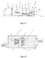
- Figures 2 to 5 illustrate some of the shortcomings of the known polishing processes using an example of a simple hollow rectangle shape with restricted internals access and some internal structures.
- Figure 2 illustrates extrude hone polishing.
- the polishing medium 5 in this case an abrasive slurry, is pumped in the direction indicated by arrows 4 through the internal passageways of an example component between its sidewalls 6 and past various internal features 7.
- the areas indicated by numeral 1 (pinch points and constrictions) within the component will generally have too much material removed as the abrasive slurry 5 is forced through these smaller gaps.
- the areas indicated by numeral 2, which are 'shadowed' areas where fluid flow is minimal will tend to be under polished.
- the areas of the component indicated with numeral 3, including the interior of the sidewalls 6, will generally be well polished by this method.
- Figure 3 illustrates electrochemical machining/polishing on the same example component as illustrated in Figure 2 .
- the polishing medium 5 is a polishing chemical serving as an electrolyte, and material is removed by dissolution when an electrical voltage is applied to the anodic work piece.
- reference numeral 1 in Figure 3 indicates the areas of the component, primarily at the corners of the internal features 7, where too much material is typically removed by this electrochemical polishing method due to current density effects at corners.
- Reference numeral 2 again indicates the areas where too little polishing occurs, mainly constricted areas of the component where the electrolyte supply is limited, while reference numeral 3 again indicates the well-polished areas.
- Figure 4 shows the barrelling process applied to the same example component.
- the component is immersed in abrasive beads, which act as the polishing medium 5, and is vibrated as indicated by the arrows 4.
- abrasive beads which act as the polishing medium 5
- polishing medium 5 which act as the polishing medium 5
- no polishing is achieved in the interior 2 of the component, but external areas 3 are well polished.
- Internal magnetorheological polishing normally involves filling the internal cavity of a component or workpiece with MR fluid, and then either moving surrounding magnets relative to the workpiece or moving the workpiece relative to the magnets to vary the applied magnetic field.
- Figure 5 shows rotating magnets 8 located around the same example component from Figures 2 to 4 , which is held stationary.
- MR fluid providing the polishing medium 5 in this example, fills the interior of the component.
- MRAFF magnetorheological abrasive flow finishing'
- the invention overcomes this problem by using AC driven electromagnets to provide a constantly varying magnetic field to the MR fluid.
- This constant modification of the magnetic field alters the rheology of the MR fluid.
- the AC field changes the polarity of the magnets on each cycle, so removes the need to either manipulate the work piece or rotate or move the magnets throughout the polishing process.
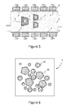
- FIG. 6 provides an example of the abrasive media from a conventional MR polishing system.
- the abrasive media 5 is a suspension of small, generally spherical ferromagnetic particles 24 and larger, angular, non-magnetic abrasive particles 26 in a fluid 25.
- the ferromagnetic particles 24 form chains which align with the magnetic field and effectively trap the abrasive particles 26 in position so that they can provide a polishing action during movement of the component and/or magnetic field.
- FIG 7A shows an example of an improved abrasive media.
- Acicular polishing media units 30 are formed by bonding or sintering abrasive silicon carbide particles 26 to the outer surface of rod-shaped ferromagnetic components 28. With no applied magnetic field, these units will form a randomly oriented suspension in the fluid 25 as shown in Figure 7A . However, when a magnetic field is applied the units 30 will be caused rotate and try to align with the magnetic field lines as shown in Figure 7B . The motion of the units 30 moving from the randomly oriented state to the aligned state provides a polishing action even in the absence of any movement of the component or variation in direction of the magnetic field.
- the magnetic component of the abrasive material is isotropic i.e. the same ferromagnetic material is used throughout each of the units but the shape of the unit, having an aspect ratio greater than 1 and preferably in the range 2 to 30, gives a magnetic saliency that concentrates magnetic flux. This saliency makes it possible to spin the particles about their own axis rather than moving as a single agglomeration.
- the polishing media has a diameter of the order 25 to 50 microns and a length between 500microns to 3mm.
- Metallic components formed by additive layer have a surface finish that is defined in part by the size of the metallic particles used in the powder bed.
- the size of the polishing media can be selected to complement the size of the particles used in the powder bed such that there is minimal work hardening caused by impact of the polishing media with the wall of the component..
- abrasive particles are described as being silicon carbide it will be appreciated that it will be possible to use other abrasives that may be better suited to the material to be polished.
- Permanent magnets could be used to drive this sort of polishing arrangement, they would still have to be constantly moved in relation to the work piece in order to continually alter the alignment of the polishing media and provide the polishing action.
- a better approach would be to use electromagnets as previously described, to stimulate the movement in the polishing media.
- the AC electromagnets could provide the required variation in applied magnetic field to move the polishing media units 30 between the states shown in Figures 7A and 7B without the need to move the magnets.
- a further benefit of using AC electromagnets is that by altering the input current the characteristics of the field variations can be easily adapted to fit particular requirements, either before or during a polishing operation. Differences in materials, MR fluid, required finish etc could all lead to different ideal or preferred alterations in the magnetic field. The alterations could be achieved in the present invention simply by using an appropriate signal generator, thus requiring little or no change to the physical arrangement of the component and the magnets.
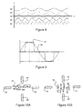
- Figure 8 shows a variety of sine waves having various frequencies.
- smaller abrasive particles suspended in a less viscous medium would respond faster to an applied magnetic field, and could therefore be driven by a higher frequency AC magnetic field, eg as represented by line 38 or 40.
- larger abrasive particles in a more viscous medium would move more slowly and would require a lower frequency wave, such as that defined by lines 34 or 36.
- Figure 9 shows a generated square wave 42 compared a standard sine wave 32 as illustrated in Figure 8 . It can be seen that the rise time from zero to peak for the square wave 42 is shortened to virtually zero. Shorter rise times are expected to increase the speed of abrasive alignment, thus making the abrasive action more energetic and therefore resulting in more rapid material removal and more aggressive MR polishing.
- An alternative arrangement would be to provide a coil 48 positioned around the outside of a component which requires internal finishing. This is illustrated in Figure 11 , using the same example component, with the same internal features 7, as illustrated in Figures 2 to 5 .
- the correct AC field could be generated to suit the magnetic properties (hysteresis) of the component being polished. Reversing the field in the coil 48 would 'flip' the polishing media and provide a polishing action.
- the process could also be optimised to suit the viscosity of the polishing fluid 5 and the size/shape of the polishing media.
- multiple coils 52,54 could be used, set at different angles relative to the component as shown in Figure 12 . These coils 52,54 could then be powered in sequence in order to maximise the motion and agitation of the MR fluid 5 within the component.
- the system described provides a method for polishing the internal structure of complex components which currently cannot be polished in any other way.
- This technology is especially important for additive layer manufactured (ALM) components due to the inherent rough surface finish from the ALM process.
- ALM additive layer manufactured
- the system comprises a suspension of acicular ferromagnetic particles, intimately bonded to a non-magnetic abrasive material, forming the magnetorheological (MR) fluid.
- the acicular abrasive is agitated by an externally applied magnetic field arranged such that it penetrates & saturates the component in order to apply a magnetic field in the internal cavities which require polishing. Alternating the direction of the field or firing different coils in sequence allow constant, controllable & adaptable control of the polishing process.
- Polishing of internal structures is beneficial for; improving fatigue life, removing burrs and defects, removing partially sintered (ALM) powder, reducing pressure drop, etc.
- ALM partially sintered
Landscapes
- Engineering & Computer Science (AREA)
- Mechanical Engineering (AREA)
- Finish Polishing, Edge Sharpening, And Grinding By Specific Grinding Devices (AREA)
Abstract
This invention concerns improvements in the polishing of internal surfaces and structures of components, particularly components with a complex internal geometry. Embodiments of the invention use an alternating current electromagnet (48) driven by a signal generator (50) to constantly alter the rheology of the magnetorheological fluid (5). An improved magnetorheological fluid (25,30) is also disclosed.
Description
- The present invention relates to the polishing of internal surfaces and structures of components. In particular, the invention relates to the polishing of internal surfaces and structures of components with a complex internal geometry, for example components for use in the aerospace industry.
- Providing a smooth surface finish on a component is often desirable. In particular in the aerospace industry, a smooth surface finish may be necessary for any one of a number of reasons including: reducing pressure loss, reducing cavitation, improving fatigue life, etc. With constant cross-section components such as pipes the polishing can be consistent across the internal surface. For complex geometries with constrictions, bends, and other variation in the cross-sectional geometries the component may be over-polished in some regions and under-polished in others.
- When components are manufactured by additive layer manufacturing (ALM) processes, the surface roughness is inherently high as a result of the powder size used during processing. There are several known ways to polish ALM, but all have certain disadvantages.
- Extrude hone polishing is a process where an abrasive slurry is pumped through the internal passageways of a component. The abrasive slurry reduces the surface roughness by grinding away surface asperities. The slurry follows a line of least resistance and works well on consistent cross sections (a bent tube or manifold) but will often not effectively polish complex shapes with many branches, channels, features and perturbations.
- Electrochemical machining/polishing is a process in which the workpiece is made the anode in an electrochemical cell. The electrolyte and applied voltage remove material from the workpiece by dissolution. The process works best on simple geometries and simple alloys. In complex geometries there can be uneven material loss due to varying current densities at corners, edges and blind holes.
- Barrelling is a polishing process where the workpiece is vibrated in a barrel full of abrasive beads which polishes the surface. This can be effective for external surfaces, but is generally unsuitable for polishing internal surfaces of a component.
- All of the abovementioned processes are limited in their application. In particular, they cannot be used for polishing the internal geometry of a complex shape of a multi-phase engineering alloy.
- Magnetorheological polishing uses a magnetorheological (MR) fluid, which is a suspension of ferromagnetic particles in a fluid, often oil. The viscosity of the fluid can be altered by application of a magnetic field which causes the ferromagnetic particles to agglomerate. This agglomeration can be used to polish a component or workpiece, particularly when hard ceramic abrasive particles are mixed with the ferromagnetic suspension. Within the magnetic field the fluid behaves as a Bingham plastic rather than a Newtonian fluid, and this Bingham plastic region can be used as an conforming, abrasive 'sanding block'.
- External polishing is normally performed by repeatedly passing the workpiece over or through the abrasive agglomeration of ferromagnetic particles. There are various different arrangements whereby the workpiece can be manipulated through the MR fluid in the presence of a magnetic field.
- Internal polishing can be achieved using magnetorheological polishing, for example by filling the internal cavity with MR fluid and moving the workpiece within an externally applied magnetic field. However, drawbacks still remain with this method.
- It is an aim of the present invention to provide an improved polishing apparatus and method that overcomes or mitigates some or all of these problems.
- According to a first aspect of the invention there is provided apparatus for polishing the internal geometry of a component with magnetorheological fluid, the apparatus comprising an electromagnet and a signal generator to drive the electromagnet, wherein the signal generator generates an alternating current such that the electromagnet produces an alternating magnetic field.
- The signal generator may be adjustable to generate different wave shapes/forms in the alternating current, and/or to generate different frequencies/wavelengths in the alternating current and/or to generate different amplitudes in the alternating current.
- The apparatus may further comprise a particular magnetorheological fluid.
- The magnetorheological fluid may comprise elongated polishing media units with an aspect ratio greater than 1, for example comprising abrasive particles bonded to the outer surface of rod-shaped ferromagnetic components. The abrasive particles may comprise silicon carbide, alumina, boron nitride or other ceramic grinding media.
- The electromagnet may comprise a coil formed around the outside of the component to be polished.
- The electromagnet may comprise a plurality of electromagnetic coils formed around the outside of the component, at least two of the coils being arranged at a non-parallel angle to each other.
- A plurality of pairs of electromagnets may be provided separate from the component, with the electromagnets within each pair being located at opposing sides of the component, and at least two of said pairs of electromagnets being arranged at non-parallel angles to each other.
- The invention also provides an improved magnetorheological fluid comprising a suspension of elongated ferromagnetic polishing media units. The ferromagnetic media units may have an homogeneous composition.
- The polishing media units may comprise abrasive particles bonded to the outer surface of rod-shaped ferromagnetic components. The abrasive may comprise silicon carbide alumina, boron nitride or other ceramic grinding media.
- The invention further provides a method of polishing the internal geometry of a component, the method comprising the steps of at least substantially filling an internal cavity of said component with a magnetorheological fluid and activating an electromagnet to apply a magnetic field to the magnetorheological fluid, wherein the electromagnet is powered by an alternating current such that it produces an alternating magnetic field to agitate the magnetorheological fluid.
- One or more characteristics of the alternating current may be altered. For example, the wave shape/form and/or the frequency/wavelength and/or the amplitude of the alternating current may be varied.
- The one or more characteristics may be altered as an initial setup step before the magnetorheological fluid is agitated. Alternatively, or additionally, the one or more characteristics may be altered while the magnetorheological fluid is agitated.
- The method may be employed with a plurality of electromagnetic coils formed around the outside of the component, at least two of the coils being arranged at a non-parallel angle to each other, with said non-parallel coils being powered sequentially.
- Alternatively, the method may be employed with a plurality of pairs of electromagnets provided separate from the component, the electromagnets within each pair being located at opposing sides of the component, and at least two of said pairs of electromagnets being arranged at non-parallel angles to each other, with said non-parallel pairs of electromagnets being powered sequentially.
- The method may use a magnetorheological fluid is as previously described.
- The invention uses an AC electromagnet to constantly alter the rheology of the MR fluid. The produced AC field will change the polarity of the magnets on each cycle, thereby removing the need to either manipulate the component/workpiece or rotate the magnets to achieve a polishing effect.
- Appropriate AC wave characteristics can also be selected to suit a particular polishing operation. Depending on the viscosity of the fluid and the size and aspect ratio of the magnetic and abrasive particle suspension, different rates of particle oscillation may be required. This can be achieved, according to the invention, by altering the characteristics of the AC current driving the magnetic field. The AC wave characteristics can be readily tuned to a specific MR fluid, abrasive and/or component with relative ease, particularly when compared to adapting the movement of a magnet or set of magnets or of the component to achieve similar effects.
- Possible features of a wave that can be altered include:
- Wave shape/form (Sine wave, square wave, etc)
- Wave length (crest to crest distance, λ)
- Frequency (length of full cycle, T)
- Rise time (function of the wave length)
- Dwell time (function of the wave shape)
- The invention also considers modifying the abrasive media to improve its efficiency or effectiveness.
- In a conventional MR polishing system the abrasive media typically comprises a suspension of small generally spherical ferromagnetic particles and larger, angular, abrasive particles. In certain embodiments of the proposed invention, the abrasive and the ferromagnetic particles are combined to form elongate acicular (rod-shaped) polishing media units. The polishing media units may comprise a rod-shaped ferromagnetic component with non-magnetic abrasive particles (eg silicon carbide) bonded to the outer surface thereof.
- With no applied magnetic field, several of these units will form a randomly oriented suspension in the MR fluid. However, when a magnetic field is applied the units will try to align with the magnetic field lines. The motion of the units moving from the randomly oriented state to the aligned state provides a polishing action.
- Although Permanent magnets could be used to drive this sort of polishing arrangement, they would have to be constantly moved in relation to the work piece in order to continually alter the alignment of the polishing media and provide the polishing action. A better approach would be to use electromagnets to stimulate the movement in the polishing media
- Powering independent pairs of coils at an angle to each other in sequence would 'flip' the alignment of the polishing media by whatever the off-set angle of the coil pairs is. Where the coil pairs are at 90° to each other and each successive power cycle flips the polishing media by 90°.
- An alternative arrangement would be a coil positioned around the outside of the component. The field in the coil could be reversed in order to 'flip' the polishing media and provide a polishing action. Using a signal generator, the correct AC field could be generated to suit the magnetic properties (hysteresis, permittivity, and saturation flux density) of the component being polished. The process could also be optimised to suit the viscosity of the polishing fluid and the size / shape of the polishing media.
- Alternatively, multiple coils could be used, set at different angles relative to the component. These could then be powered in sequence in order to maximise the motion and agitation of the MR fluid.
- Wherever practicable, any of the essential or preferable features defined in relation to any one aspect of the invention may be applied to any further aspect. Accordingly the invention may comprise various alternative configurations of the features defined above.
- Practicable embodiments of the invention are described in further detail below by way of example only with reference to the accompanying drawings, of which:
-
Fig. 1 shows a schematic view of a gas turbine engine; -
Fig. 2 shows a schematic view of extrude hone polishing applied to an example component; -
Fig. 3 shows a schematic view of electrochemical machining/polishing applied to an example component; -
Fig. 4 shows a schematic view of barrelling applied to an example component; -
Fig. 5 shows a schematic view of magnetorheological polishing using externally manipulated permanent magnets applied to an example component; -
Fig. 6 shows an example of a typical magnetorheological fluid with abrasive and ferromagnetic particles in suspension; -
Fig. 7A and 7B show an example of an improved magnetorheological fluid; -
Fig. 8 shows a series of sine waves of varying frequencies which could be provided as inputs to the system of the invention; -
Fig. 9 shows a square wave pattern which could be provided as an input to the system of the invention; -
Fig. 10A and 10B show a possible arrangement of electromagnet coils; -
Fig. 11 shows a single electromagnet coil surrounding an example component; and -
Fig. 12 shows a pair of electromagnet coils surrounding an example component. - With reference to
Figure 1 , a ducted fan gas turbine engine generally indicated at 10 has a principal androtational axis 11. Theengine 10 comprises, in axial flow series, anair intake 12, apropulsive fan 13, anintermediate pressure compressor 14, a high-pressure compressor 15,combustion equipment 16, a high-pressure turbine 17, andintermediate pressure turbine 18, a low-pressure turbine 19 and a coreengine exhaust nozzle 20. Anacelle 21 generally surrounds theengine 10 and defines theintake 12, abypass duct 22 and abypass exhaust nozzle 23. - The
gas turbine engine 10 works in a conventional manner so that air entering theintake 12 is accelerated by thefan 13 to produce two air flows: a first air flow into theintermediate pressure compressor 14 and a second air flow which passes through abypass duct 22 to provide propulsive thrust. Theintermediate pressure compressor 14 compresses the air flow directed into it before delivering that air to thehigh pressure compressor 15 where further compression takes place. - The compressed air exhausted from the high-
pressure compressor 15 is directed into thecombustion equipment 16 where it is mixed with fuel and the mixture combusted. The resultant hot combustion products then expand through, and thereby drive the high, intermediate and low-pressure turbines nozzle 20 to provide additional propulsive thrust. The high, intermediate and low-pressure turbines intermediate pressure compressors fan 13 by suitable interconnecting shafts. - Alternative gas turbine engine arrangements may comprise a two, as opposed to three, shaft arrangement and/or may provide for different bypass ratios. Other configurations known to the skilled person include geared turbofan engines, open rotor designs, such as turboprop engines, or else turbojets, in which the bypass duct is removed such that all air flow passes through the core engine. In certain configurations, the torque from one or more engine shaft may be used to generate electrical power instead of, or in addition to, driving airflow. The various available gas turbine engine configurations are typically adapted to suit an intended operation which may include aerospace, marine, power generation amongst other propulsion or industrial pumping applications.
-
Figures 2 to 5 illustrate some of the shortcomings of the known polishing processes using an example of a simple hollow rectangle shape with restricted internals access and some internal structures. -
Figure 2 illustrates extrude hone polishing. The polishingmedium 5, in this case an abrasive slurry, is pumped in the direction indicated byarrows 4 through the internal passageways of an example component between itssidewalls 6 and past variousinternal features 7. - In the illustrated example, the areas indicated by numeral 1 (pinch points and constrictions) within the component will generally have too much material removed as the
abrasive slurry 5 is forced through these smaller gaps. In contrast, the areas indicated bynumeral 2, which are 'shadowed' areas where fluid flow is minimal, will tend to be under polished. The areas of the component indicated withnumeral 3, including the interior of thesidewalls 6, will generally be well polished by this method. -
Figure 3 illustrates electrochemical machining/polishing on the same example component as illustrated inFigure 2 . In this example the polishingmedium 5 is a polishing chemical serving as an electrolyte, and material is removed by dissolution when an electrical voltage is applied to the anodic work piece. - As in
Figure 2 ,reference numeral 1 inFigure 3 indicates the areas of the component, primarily at the corners of theinternal features 7, where too much material is typically removed by this electrochemical polishing method due to current density effects at corners.Reference numeral 2 again indicates the areas where too little polishing occurs, mainly constricted areas of the component where the electrolyte supply is limited, whilereference numeral 3 again indicates the well-polished areas. -
Figure 4 shows the barrelling process applied to the same example component. The component is immersed in abrasive beads, which act as the polishingmedium 5, and is vibrated as indicated by thearrows 4. As mentioned above, no polishing is achieved in theinterior 2 of the component, butexternal areas 3 are well polished. - Internal magnetorheological polishing normally involves filling the internal cavity of a component or workpiece with MR fluid, and then either moving surrounding magnets relative to the workpiece or moving the workpiece relative to the magnets to vary the applied magnetic field.
Figure 5 showsrotating magnets 8 located around the same example component fromFigures 2 to 4 , which is held stationary. MR fluid, providing the polishingmedium 5 in this example, fills the interior of the component. - This 'rotational magnetorheological abrasive flow finishing' (MRAFF) is a relatively new technology, but has been demonstrated on flat plate samples with great success. However, in the case of the sample geometry presented in
Figure 5 , the magnetic flux density is at its lowest in the centre of the component, exactly where the structure is most complex and requires the most polishing. The magnetic field therefore has less influence on the MR fluid in the central region, and inertia of the fluid means that movement of the component or of the magnets may not be reflected in the fluid in this central region. This results in incomplete or insufficient polishing around some of theinternal features 7, as indicated byreference numeral 2 inFigure 5 . Other regions of the component, indicated byreference numeral 3 and located nearer to themagnets 8, would be well polished. - The invention overcomes this problem by using AC driven electromagnets to provide a constantly varying magnetic field to the MR fluid. This constant modification of the magnetic field alters the rheology of the MR fluid. The AC field changes the polarity of the magnets on each cycle, so removes the need to either manipulate the work piece or rotate or move the magnets throughout the polishing process.
-
Figure 6 provides an example of the abrasive media from a conventional MR polishing system. Theabrasive media 5 is a suspension of small, generally sphericalferromagnetic particles 24 and larger, angular, non-magneticabrasive particles 26 in afluid 25. When a magnetic field is applied, theferromagnetic particles 24 form chains which align with the magnetic field and effectively trap theabrasive particles 26 in position so that they can provide a polishing action during movement of the component and/or magnetic field. -
Figure 7A shows an example of an improved abrasive media. Acicular polishingmedia units 30 are formed by bonding or sintering abrasivesilicon carbide particles 26 to the outer surface of rod-shapedferromagnetic components 28. With no applied magnetic field, these units will form a randomly oriented suspension in the fluid 25 as shown inFigure 7A . However, when a magnetic field is applied theunits 30 will be caused rotate and try to align with the magnetic field lines as shown inFigure 7B . The motion of theunits 30 moving from the randomly oriented state to the aligned state provides a polishing action even in the absence of any movement of the component or variation in direction of the magnetic field. - The magnetic component of the abrasive material is isotropic i.e. the same ferromagnetic material is used throughout each of the units but the shape of the unit, having an aspect ratio greater than 1 and preferably in the
range 2 to 30, gives a magnetic saliency that concentrates magnetic flux. This saliency makes it possible to spin the particles about their own axis rather than moving as a single agglomeration. - The polishing media has a diameter of the
order 25 to 50 microns and a length between 500microns to 3mm. Metallic components formed by additive layer have a surface finish that is defined in part by the size of the metallic particles used in the powder bed. The size of the polishing media can be selected to complement the size of the particles used in the powder bed such that there is minimal work hardening caused by impact of the polishing media with the wall of the component.. - Although the abrasive particles are described as being silicon carbide it will be appreciated that it will be possible to use other abrasives that may be better suited to the material to be polished.
- Although Permanent magnets could be used to drive this sort of polishing arrangement, they would still have to be constantly moved in relation to the work piece in order to continually alter the alignment of the polishing media and provide the polishing action. A better approach would be to use electromagnets as previously described, to stimulate the movement in the polishing media. The AC electromagnets could provide the required variation in applied magnetic field to move the polishing
media units 30 between the states shown inFigures 7A and 7B without the need to move the magnets. - A further benefit of using AC electromagnets is that by altering the input current the characteristics of the field variations can be easily adapted to fit particular requirements, either before or during a polishing operation. Differences in materials, MR fluid, required finish etc could all lead to different ideal or preferred alterations in the magnetic field. The alterations could be achieved in the present invention simply by using an appropriate signal generator, thus requiring little or no change to the physical arrangement of the component and the magnets.
- One alteration would be to adapt the frequency of the input signal.
Figure 8 shows a variety of sine waves having various frequencies. Abasic sine wave 32, representing y = Sin x, is illustrated in the centre of the graph. Lower frequency waves 34,36, corresponding to y = Sin 0.8x and y = Sin 0.6x respectively, are shown shifted upwards on the y axis for clarity. Similarly, higher frequency waves 38,40, corresponding to y = Sin 1.3x and y = Sin 2.6x respectively, are shown shifted downwards on the y axis. It is anticipated that smaller abrasive particles suspended in a less viscous medium would respond faster to an applied magnetic field, and could therefore be driven by a higher frequency AC magnetic field, eg as represented byline lines - Alternatively, or additionally, the shape of the wave could be modified. For example,
Figure 9 shows a generatedsquare wave 42 compared astandard sine wave 32 as illustrated inFigure 8 . It can be seen that the rise time from zero to peak for thesquare wave 42 is shortened to virtually zero. Shorter rise times are expected to increase the speed of abrasive alignment, thus making the abrasive action more energetic and therefore resulting in more rapid material removal and more aggressive MR polishing. - It should be understood that numerous other modifications could be made to the waveform to alter one or more of the wave shape, wavelength or period, rise time, dwell time, frequency or amplitude as required for a particular operation.
- While numerous modifications are possible as set out above, the resulting changes in the MR fluid will all take place in the direction of alignment of the magnets. It may therefore be beneficial to provide an arrangement of magnets that provides changes in various different directions. For example, independent pairs of coils could be provided at an angle to each other. This is illustrated in
Figures 10A and 10B , where two pairs ofcoils media units 30 by whatever the off-set angle of the coil pairs is. As shown, the polishingmedia units 30 are 'flipped' by 90° from the position shown inFigure 10A (44-on, 46-off) to that shown inFigure 10B (46-on, 44-off). - An alternative arrangement would be to provide a
coil 48 positioned around the outside of a component which requires internal finishing. This is illustrated inFigure 11 , using the same example component, with the sameinternal features 7, as illustrated inFigures 2 to 5 . Using asignal generator 50, the correct AC field could be generated to suit the magnetic properties (hysteresis) of the component being polished. Reversing the field in thecoil 48 would 'flip' the polishing media and provide a polishing action. The process could also be optimised to suit the viscosity of the polishingfluid 5 and the size/shape of the polishing media. - Instead of the
single coil 48 sown inFigure 11 ,multiple coils Figure 12 . Thesecoils MR fluid 5 within the component. - It would also be possible to provide for electromagnetic pumping of the MR fluid by sequential powering of coils such as the
multiple coils Figure 12 or a sequence ofcoils 48 as shown inFigure 11 , in order to create a constant through-flow of MR fluid rather than localised agitation within a component. - The system described provides a method for polishing the internal structure of complex components which currently cannot be polished in any other way. This technology is especially important for additive layer manufactured (ALM) components due to the inherent rough surface finish from the ALM process.
- In certain embodiments, the system comprises a suspension of acicular ferromagnetic particles, intimately bonded to a non-magnetic abrasive material, forming the magnetorheological (MR) fluid. The acicular abrasive is agitated by an externally applied magnetic field arranged such that it penetrates & saturates the component in order to apply a magnetic field in the internal cavities which require polishing. Alternating the direction of the field or firing different coils in sequence allow constant, controllable & adaptable control of the polishing process.
- Polishing of internal structures is beneficial for; improving fatigue life, removing burrs and defects, removing partially sintered (ALM) powder, reducing pressure drop, etc. This invention has great potential to help ALM reach its full potential in the field of integrated internal features and minimum mass structures.
Claims (15)
- Apparatus for polishing the internal geometry of a component with magnetorheological fluid (5), the apparatus comprising an electromagnet and a signal generator (50) to drive the electromagnet, wherein the signal generator generates an alternating current such that the electromagnet produces an alternating magnetic field.
- Apparatus according to claim 1, further comprising magnetorheological fluid. (5) comprising elongate polishing media units (30).
- Apparatus according to claim 2, wherein the polishing media units comprise abrasive particles (26) bonded to the outer surface of rod-shaped ferromagnetic components (28).
- Apparatus according to claim 3, wherein the abrasive particles (26) comprise a ceramic grinding media.
- Apparatus according to any of the preceding claims, wherein a plurality of electromagnetic coils (52,54) are formed around the outside of the component, at least two of the coils being arranged at a non-parallel angle to each other.
- Apparatus according to any of claims 1 to 4, wherein a plurality of pairs (44, 46) of electromagnets are provided separate from the component, the electromagnets within each pair being located at opposing sides of the component, and at least two of said pairs of electromagnets being arranged at non-parallel angles to each other.
- A method of polishing the internal geometry of a component, the method comprising the steps of at least substantially filling an internal cavity of said component with a magnetorheological fluid and activating an electromagnet to apply a magnetic field to the magnetorheological fluid, wherein the electromagnet is powered by an alternating current such that it produces an alternating magnetic field to agitate the magnetorheological fluid.
- A method according to claim 7, further comprising altering one or more characteristics of the alternating current.
- A method according to claim 8, wherein the one or more characteristics is altered as an initial setup step before the magnetorheological fluid is agitated.
- A method according to claim 8 or 9, wherein the one or more characteristics is altered while the magnetorheological fluid is agitated.
- A method according to any of claims 8 to 10, wherein the wave form of the alternating current is varied.
- A method according to any of claims 8 to 11, wherein the frequency of the alternating current is varied.
- A method according to any of claims 8 to 12, wherein a plurality of electromagnetic coils (52, 54) are formed around the outside of the component, at least two of the coils being arranged at a non-parallel angle to each other, and wherein said non-parallel coils are powered sequentially.
- A method according to any of claims 8 to 12, wherein a plurality of pairs (46,44) of electromagnets are provided separate from the component, the electromagnets within each pair being located at opposing sides of the component, and at least two of said pairs of electromagnets being arranged at non-parallel angles to each other, and wherein said non-parallel pairs of electromagnets are powered sequentially.
- A method according to any of claims 7 to 14 wherein the magnetorheological fluid (5) comprises a suspension of elongate ferromagnetic polishing media (30) units comprising abrasive particles (26) bonded to the outer surface of rod-shaped ferromagnetic components (28).
Applications Claiming Priority (1)
| Application Number | Priority Date | Filing Date | Title |
|---|---|---|---|
| GBGB1511119.8A GB201511119D0 (en) | 2015-06-24 | 2015-06-24 | Polishing of complex internal geometries |
Publications (1)
| Publication Number | Publication Date |
|---|---|
| EP3109000A1 true EP3109000A1 (en) | 2016-12-28 |
Family
ID=53784450
Family Applications (1)
| Application Number | Title | Priority Date | Filing Date |
|---|---|---|---|
| EP16174729.0A Withdrawn EP3109000A1 (en) | 2015-06-24 | 2016-06-16 | Polishing of complex internal geometries |
Country Status (3)
| Country | Link |
|---|---|
| US (1) | US20160375538A1 (en) |
| EP (1) | EP3109000A1 (en) |
| GB (1) | GB201511119D0 (en) |
Cited By (3)
| Publication number | Priority date | Publication date | Assignee | Title |
|---|---|---|---|---|
| CN108044495A (en) * | 2018-01-28 | 2018-05-18 | 吉林大学 | A kind of distant manipulation instrument in magnetic field orients burnishing device and polishing method |
| CN109531431A (en) * | 2019-01-14 | 2019-03-29 | 中国工程物理研究院机械制造工艺研究所 | A kind of circulator of Magnetorheologicai polishing liquid |
| CN114043319A (en) * | 2021-11-24 | 2022-02-15 | 浙江科惠医疗器械股份有限公司 | Medical multi-stage constant-speed self-circulation magnetorheological polishing machine with wire anchors |
Families Citing this family (6)
| Publication number | Priority date | Publication date | Assignee | Title |
|---|---|---|---|---|
| WO2018080756A1 (en) * | 2016-10-25 | 2018-05-03 | 3M Innovative Properties Company | Functional abrasive particles, abrasive articles, and methods of making the same |
| GB201713300D0 (en) * | 2017-08-18 | 2017-10-04 | Rolls Royce Plc | Surface modification using abrasive blasting |
| CN108436744A (en) * | 2018-05-21 | 2018-08-24 | 浙江工业大学 | A kind of continually changing liquid metal burnishing device of electric field |
| CN110640614B (en) * | 2019-10-16 | 2024-04-09 | 浙江工业大学 | Negative pressure polishing device and method for polishing blind holes of conductive workpiece |
| CN110640615B (en) * | 2019-10-16 | 2024-04-09 | 浙江工业大学 | Liquid metal magnetic polishing device for blind hole polishing and method thereof |
| CN113977358A (en) * | 2021-10-16 | 2022-01-28 | 毕而达 | Automatic control rotating magnetic field magneto-rheological polishing machine |
Citations (7)
| Publication number | Priority date | Publication date | Assignee | Title |
|---|---|---|---|---|
| US2735231A (en) * | 1953-05-22 | 1956-02-21 | Reflectone Corp | simjian |
| US2880554A (en) * | 1956-01-03 | 1959-04-07 | Reflectone Corp | Treating or polishing apparatus |
| US3533928A (en) * | 1969-04-21 | 1970-10-13 | Inoue K | Method of and apparatus for the deburring of workpieces |
| WO2000062974A1 (en) * | 1999-04-21 | 2000-10-26 | H-Semitran Llc | Ferrofluidic finishing |
| JP2006272520A (en) * | 2005-03-30 | 2006-10-12 | Utsunomiya Univ | Magnetically assisted machining method and magnetic tool used therefor |
| JP2007136295A (en) * | 2005-11-16 | 2007-06-07 | Utsunomiya Univ | In-pipe cleaning device using rotating electromagnetic field |
| US20130273816A1 (en) * | 2012-04-13 | 2013-10-17 | Nano And Advanced Materials Institute Limited | Automatic polishing device for surface finishing of complex-curved-profile parts |
Family Cites Families (4)
| Publication number | Priority date | Publication date | Assignee | Title |
|---|---|---|---|---|
| JPH10180611A (en) * | 1996-12-24 | 1998-07-07 | Takahiro Imahashi | Magnetic grinding method and device based on generation of plurality of alternating fields |
| WO2001007206A1 (en) * | 1999-07-27 | 2001-02-01 | Japan Science And Technology Corporation | Surface treating method and device using magnetic-anisotropy tool |
| JP5438091B2 (en) * | 2009-02-17 | 2014-03-12 | クリノ株式会社 | Method for manufacturing cylindrical structure and stent |
| US20160101706A1 (en) * | 2014-10-14 | 2016-04-14 | Carl Lee Danner | Charging System for Electric Vehicles |
-
2015
- 2015-06-24 GB GBGB1511119.8A patent/GB201511119D0/en not_active Ceased
-
2016
- 2016-06-16 US US15/184,545 patent/US20160375538A1/en not_active Abandoned
- 2016-06-16 EP EP16174729.0A patent/EP3109000A1/en not_active Withdrawn
Patent Citations (7)
| Publication number | Priority date | Publication date | Assignee | Title |
|---|---|---|---|---|
| US2735231A (en) * | 1953-05-22 | 1956-02-21 | Reflectone Corp | simjian |
| US2880554A (en) * | 1956-01-03 | 1959-04-07 | Reflectone Corp | Treating or polishing apparatus |
| US3533928A (en) * | 1969-04-21 | 1970-10-13 | Inoue K | Method of and apparatus for the deburring of workpieces |
| WO2000062974A1 (en) * | 1999-04-21 | 2000-10-26 | H-Semitran Llc | Ferrofluidic finishing |
| JP2006272520A (en) * | 2005-03-30 | 2006-10-12 | Utsunomiya Univ | Magnetically assisted machining method and magnetic tool used therefor |
| JP2007136295A (en) * | 2005-11-16 | 2007-06-07 | Utsunomiya Univ | In-pipe cleaning device using rotating electromagnetic field |
| US20130273816A1 (en) * | 2012-04-13 | 2013-10-17 | Nano And Advanced Materials Institute Limited | Automatic polishing device for surface finishing of complex-curved-profile parts |
Cited By (4)
| Publication number | Priority date | Publication date | Assignee | Title |
|---|---|---|---|---|
| CN108044495A (en) * | 2018-01-28 | 2018-05-18 | 吉林大学 | A kind of distant manipulation instrument in magnetic field orients burnishing device and polishing method |
| CN109531431A (en) * | 2019-01-14 | 2019-03-29 | 中国工程物理研究院机械制造工艺研究所 | A kind of circulator of Magnetorheologicai polishing liquid |
| CN109531431B (en) * | 2019-01-14 | 2024-04-16 | 中国工程物理研究院机械制造工艺研究所 | Circulation device of magnetorheological polishing liquid |
| CN114043319A (en) * | 2021-11-24 | 2022-02-15 | 浙江科惠医疗器械股份有限公司 | Medical multi-stage constant-speed self-circulation magnetorheological polishing machine with wire anchors |
Also Published As
| Publication number | Publication date |
|---|---|
| US20160375538A1 (en) | 2016-12-29 |
| GB201511119D0 (en) | 2015-08-05 |
Similar Documents
| Publication | Publication Date | Title |
|---|---|---|
| EP3109000A1 (en) | Polishing of complex internal geometries | |
| Jain | Magnetic field assisted abrasive based micro-/nano-finishing | |
| Wang et al. | Study on the inner surface finishing of tubing by magnetic abrasive finishing | |
| Kajal et al. | Experimental and theoretical investigations into internal magnetic abrasive finishing of a revolver barrel | |
| Fox et al. | Magnetic abrasive finishing of rollers | |
| CN205817470U (en) | A kind of from supercharging high speed abrasive particle magnetic current threaded hole inner surface burnishing device | |
| US6146243A (en) | Method and apparatus for finishing works magnetically by generating alternating magnetic fields | |
| CN104551966A (en) | Magnetorheological fluid adaptive planar processing system | |
| Li et al. | Multi-pole magnetorheological shear thickening polishing on inner surface of aluminum alloy slender tubes | |
| Maan et al. | Nano-surface finishing of hardened AISI 52100 steel using magnetorheological solid core rotating tool | |
| Niranjan et al. | Experimental investigation into tool aging effect in ball end magnetorheological finishing | |
| Kumar et al. | Study of surface finishing mechanism in a rotational-magnetorheological miniature gear profile polishing using novel flow restrictor | |
| CN112123029A (en) | A microstructure vibration smoothing device and smoothing method based on magnetic field assistance | |
| Wang et al. | Elucidating the optimal parameters in magnetic finishing with gel abrasive | |
| JP2002264007A (en) | Magnetic assisted polishing method and apparatus for inner surface of bent pipe | |
| Chou et al. | Elucidating the rheological effect of gel abrasives in magnetic abrasive finishing | |
| CN218891674U (en) | Flexible processingequipment of self-adaptation face formula | |
| CN115922450A (en) | Flexible processing method and device for adaptive surface shape | |
| Kumar et al. | Performance evaluation of rotational-magnetorheological glass–ceramic polishing (R-MRGP) process setups | |
| JP2019147193A (en) | Polishing method and method for production of ceramic product | |
| Kumar et al. | Parametric investigations into internal surface modification of brass tubes with alternating magnetic field | |
| CN117697541A (en) | Surface polishing device and method based on magnetic stirring | |
| Grover et al. | Improved design of magnetorheological honing tool based on finite element analysis and experimental examination of its performance | |
| CN106425704B (en) | The Magnetorheological Polishing grinding wheel device in open magnetic field | |
| Kunar et al. | Magnetic Abrasive Finishing Process |
Legal Events
| Date | Code | Title | Description |
|---|---|---|---|
| PUAI | Public reference made under article 153(3) epc to a published international application that has entered the european phase |
Free format text: ORIGINAL CODE: 0009012 |
|
| STAA | Information on the status of an ep patent application or granted ep patent |
Free format text: STATUS: THE APPLICATION HAS BEEN PUBLISHED |
|
| AK | Designated contracting states |
Kind code of ref document: A1 Designated state(s): AL AT BE BG CH CY CZ DE DK EE ES FI FR GB GR HR HU IE IS IT LI LT LU LV MC MK MT NL NO PL PT RO RS SE SI SK SM TR |
|
| AX | Request for extension of the european patent |
Extension state: BA ME |
|
| STAA | Information on the status of an ep patent application or granted ep patent |
Free format text: STATUS: THE APPLICATION IS DEEMED TO BE WITHDRAWN |
|
| 18D | Application deemed to be withdrawn |
Effective date: 20170629 |