EP3108994A1 - Methods for treating field operated components - Google Patents
Methods for treating field operated components Download PDFInfo
- Publication number
- EP3108994A1 EP3108994A1 EP16175272.0A EP16175272A EP3108994A1 EP 3108994 A1 EP3108994 A1 EP 3108994A1 EP 16175272 A EP16175272 A EP 16175272A EP 3108994 A1 EP3108994 A1 EP 3108994A1
- Authority
- EP
- European Patent Office
- Prior art keywords
- component
- field operated
- matrix composite
- ceramic matrix
- joint
- Prior art date
- Legal status (The legal status is an assumption and is not a legal conclusion. Google has not performed a legal analysis and makes no representation as to the accuracy of the status listed.)
- Granted
Links
Images

Classifications
-
- F—MECHANICAL ENGINEERING; LIGHTING; HEATING; WEAPONS; BLASTING
- F01—MACHINES OR ENGINES IN GENERAL; ENGINE PLANTS IN GENERAL; STEAM ENGINES
- F01D—NON-POSITIVE DISPLACEMENT MACHINES OR ENGINES, e.g. STEAM TURBINES
- F01D5/00—Blades; Blade-carrying members; Heating, heat-insulating, cooling or antivibration means on the blades or the members
- F01D5/12—Blades
- F01D5/14—Form or construction
-
- B—PERFORMING OPERATIONS; TRANSPORTING
- B23—MACHINE TOOLS; METAL-WORKING NOT OTHERWISE PROVIDED FOR
- B23P—METAL-WORKING NOT OTHERWISE PROVIDED FOR; COMBINED OPERATIONS; UNIVERSAL MACHINE TOOLS
- B23P6/00—Restoring or reconditioning objects
- B23P6/002—Repairing turbine components, e.g. moving or stationary blades, rotors
- B23P6/005—Repairing turbine components, e.g. moving or stationary blades, rotors using only replacement pieces of a particular form
-
- B—PERFORMING OPERATIONS; TRANSPORTING
- B28—WORKING CEMENT, CLAY, OR STONE
- B28B—SHAPING CLAY OR OTHER CERAMIC COMPOSITIONS; SHAPING SLAG; SHAPING MIXTURES CONTAINING CEMENTITIOUS MATERIAL, e.g. PLASTER
- B28B1/00—Producing shaped prefabricated articles from the material
- B28B1/002—Producing shaped prefabricated articles from the material assembled from preformed elements
-
- B—PERFORMING OPERATIONS; TRANSPORTING
- B29—WORKING OF PLASTICS; WORKING OF SUBSTANCES IN A PLASTIC STATE IN GENERAL
- B29C—SHAPING OR JOINING OF PLASTICS; SHAPING OF MATERIAL IN A PLASTIC STATE, NOT OTHERWISE PROVIDED FOR; AFTER-TREATMENT OF THE SHAPED PRODUCTS, e.g. REPAIRING
- B29C65/00—Joining or sealing of preformed parts, e.g. welding of plastics materials; Apparatus therefor
- B29C65/002—Joining methods not otherwise provided for
-
- B—PERFORMING OPERATIONS; TRANSPORTING
- B29—WORKING OF PLASTICS; WORKING OF SUBSTANCES IN A PLASTIC STATE IN GENERAL
- B29C—SHAPING OR JOINING OF PLASTICS; SHAPING OF MATERIAL IN A PLASTIC STATE, NOT OTHERWISE PROVIDED FOR; AFTER-TREATMENT OF THE SHAPED PRODUCTS, e.g. REPAIRING
- B29C65/00—Joining or sealing of preformed parts, e.g. welding of plastics materials; Apparatus therefor
- B29C65/02—Joining or sealing of preformed parts, e.g. welding of plastics materials; Apparatus therefor by heating, with or without pressure
-
- C—CHEMISTRY; METALLURGY
- C04—CEMENTS; CONCRETE; ARTIFICIAL STONE; CERAMICS; REFRACTORIES
- C04B—LIME, MAGNESIA; SLAG; CEMENTS; COMPOSITIONS THEREOF, e.g. MORTARS, CONCRETE OR LIKE BUILDING MATERIALS; ARTIFICIAL STONE; CERAMICS; REFRACTORIES; TREATMENT OF NATURAL STONE
- C04B37/00—Joining burned ceramic articles with other burned ceramic articles or other articles by heating
- C04B37/003—Joining burned ceramic articles with other burned ceramic articles or other articles by heating by means of an interlayer consisting of a combination of materials selected from glass, or ceramic material with metals, metal oxides or metal salts
- C04B37/005—Joining burned ceramic articles with other burned ceramic articles or other articles by heating by means of an interlayer consisting of a combination of materials selected from glass, or ceramic material with metals, metal oxides or metal salts consisting of glass or ceramic material
-
- F—MECHANICAL ENGINEERING; LIGHTING; HEATING; WEAPONS; BLASTING
- F01—MACHINES OR ENGINES IN GENERAL; ENGINE PLANTS IN GENERAL; STEAM ENGINES
- F01D—NON-POSITIVE DISPLACEMENT MACHINES OR ENGINES, e.g. STEAM TURBINES
- F01D25/00—Component parts, details, or accessories, not provided for in, or of interest apart from, other groups
- F01D25/005—Selecting particular materials
-
- F—MECHANICAL ENGINEERING; LIGHTING; HEATING; WEAPONS; BLASTING
- F01—MACHINES OR ENGINES IN GENERAL; ENGINE PLANTS IN GENERAL; STEAM ENGINES
- F01D—NON-POSITIVE DISPLACEMENT MACHINES OR ENGINES, e.g. STEAM TURBINES
- F01D25/00—Component parts, details, or accessories, not provided for in, or of interest apart from, other groups
- F01D25/24—Casings; Casing parts, e.g. diaphragms, casing fastenings
- F01D25/246—Fastening of diaphragms or stator-rings
-
- F—MECHANICAL ENGINEERING; LIGHTING; HEATING; WEAPONS; BLASTING
- F01—MACHINES OR ENGINES IN GENERAL; ENGINE PLANTS IN GENERAL; STEAM ENGINES
- F01D—NON-POSITIVE DISPLACEMENT MACHINES OR ENGINES, e.g. STEAM TURBINES
- F01D25/00—Component parts, details, or accessories, not provided for in, or of interest apart from, other groups
- F01D25/30—Exhaust heads, chambers, or the like
-
- F—MECHANICAL ENGINEERING; LIGHTING; HEATING; WEAPONS; BLASTING
- F01—MACHINES OR ENGINES IN GENERAL; ENGINE PLANTS IN GENERAL; STEAM ENGINES
- F01D—NON-POSITIVE DISPLACEMENT MACHINES OR ENGINES, e.g. STEAM TURBINES
- F01D5/00—Blades; Blade-carrying members; Heating, heat-insulating, cooling or antivibration means on the blades or the members
- F01D5/005—Repairing methods or devices
-
- F—MECHANICAL ENGINEERING; LIGHTING; HEATING; WEAPONS; BLASTING
- F01—MACHINES OR ENGINES IN GENERAL; ENGINE PLANTS IN GENERAL; STEAM ENGINES
- F01D—NON-POSITIVE DISPLACEMENT MACHINES OR ENGINES, e.g. STEAM TURBINES
- F01D5/00—Blades; Blade-carrying members; Heating, heat-insulating, cooling or antivibration means on the blades or the members
- F01D5/12—Blades
- F01D5/14—Form or construction
- F01D5/18—Hollow blades, i.e. blades with cooling or heating channels or cavities; Heating, heat-insulating or cooling means on blades
- F01D5/187—Convection cooling
-
- F—MECHANICAL ENGINEERING; LIGHTING; HEATING; WEAPONS; BLASTING
- F01—MACHINES OR ENGINES IN GENERAL; ENGINE PLANTS IN GENERAL; STEAM ENGINES
- F01D—NON-POSITIVE DISPLACEMENT MACHINES OR ENGINES, e.g. STEAM TURBINES
- F01D5/00—Blades; Blade-carrying members; Heating, heat-insulating, cooling or antivibration means on the blades or the members
- F01D5/12—Blades
- F01D5/28—Selecting particular materials; Particular measures relating thereto; Measures against erosion or corrosion
- F01D5/282—Selecting composite materials, e.g. blades with reinforcing filaments
-
- F—MECHANICAL ENGINEERING; LIGHTING; HEATING; WEAPONS; BLASTING
- F01—MACHINES OR ENGINES IN GENERAL; ENGINE PLANTS IN GENERAL; STEAM ENGINES
- F01D—NON-POSITIVE DISPLACEMENT MACHINES OR ENGINES, e.g. STEAM TURBINES
- F01D5/00—Blades; Blade-carrying members; Heating, heat-insulating, cooling or antivibration means on the blades or the members
- F01D5/12—Blades
- F01D5/28—Selecting particular materials; Particular measures relating thereto; Measures against erosion or corrosion
- F01D5/284—Selection of ceramic materials
-
- F—MECHANICAL ENGINEERING; LIGHTING; HEATING; WEAPONS; BLASTING
- F01—MACHINES OR ENGINES IN GENERAL; ENGINE PLANTS IN GENERAL; STEAM ENGINES
- F01D—NON-POSITIVE DISPLACEMENT MACHINES OR ENGINES, e.g. STEAM TURBINES
- F01D5/00—Blades; Blade-carrying members; Heating, heat-insulating, cooling or antivibration means on the blades or the members
- F01D5/12—Blades
- F01D5/28—Selecting particular materials; Particular measures relating thereto; Measures against erosion or corrosion
- F01D5/286—Particular treatment of blades, e.g. to increase durability or resistance against corrosion or erosion
-
- F—MECHANICAL ENGINEERING; LIGHTING; HEATING; WEAPONS; BLASTING
- F01—MACHINES OR ENGINES IN GENERAL; ENGINE PLANTS IN GENERAL; STEAM ENGINES
- F01D—NON-POSITIVE DISPLACEMENT MACHINES OR ENGINES, e.g. STEAM TURBINES
- F01D5/00—Blades; Blade-carrying members; Heating, heat-insulating, cooling or antivibration means on the blades or the members
- F01D5/12—Blades
- F01D5/28—Selecting particular materials; Particular measures relating thereto; Measures against erosion or corrosion
- F01D5/288—Protective coatings for blades
-
- F—MECHANICAL ENGINEERING; LIGHTING; HEATING; WEAPONS; BLASTING
- F01—MACHINES OR ENGINES IN GENERAL; ENGINE PLANTS IN GENERAL; STEAM ENGINES
- F01D—NON-POSITIVE DISPLACEMENT MACHINES OR ENGINES, e.g. STEAM TURBINES
- F01D9/00—Stators
- F01D9/02—Nozzles; Nozzle boxes; Stator blades; Guide conduits, e.g. individual nozzles
-
- F—MECHANICAL ENGINEERING; LIGHTING; HEATING; WEAPONS; BLASTING
- F02—COMBUSTION ENGINES; HOT-GAS OR COMBUSTION-PRODUCT ENGINE PLANTS
- F02K—JET-PROPULSION PLANTS
- F02K1/00—Plants characterised by the form or arrangement of the jet pipe or nozzle; Jet pipes or nozzles peculiar thereto
- F02K1/78—Other construction of jet pipes
- F02K1/82—Jet pipe walls, e.g. liners
-
- F—MECHANICAL ENGINEERING; LIGHTING; HEATING; WEAPONS; BLASTING
- F02—COMBUSTION ENGINES; HOT-GAS OR COMBUSTION-PRODUCT ENGINE PLANTS
- F02K—JET-PROPULSION PLANTS
- F02K1/00—Plants characterised by the form or arrangement of the jet pipe or nozzle; Jet pipes or nozzles peculiar thereto
- F02K1/78—Other construction of jet pipes
- F02K1/82—Jet pipe walls, e.g. liners
- F02K1/822—Heat insulating structures or liners, cooling arrangements, e.g. post combustion liners; Infrared radiation suppressors
-
- F—MECHANICAL ENGINEERING; LIGHTING; HEATING; WEAPONS; BLASTING
- F02—COMBUSTION ENGINES; HOT-GAS OR COMBUSTION-PRODUCT ENGINE PLANTS
- F02K—JET-PROPULSION PLANTS
- F02K1/00—Plants characterised by the form or arrangement of the jet pipe or nozzle; Jet pipes or nozzles peculiar thereto
- F02K1/78—Other construction of jet pipes
- F02K1/82—Jet pipe walls, e.g. liners
- F02K1/827—Sound absorbing structures or liners
-
- B—PERFORMING OPERATIONS; TRANSPORTING
- B29—WORKING OF PLASTICS; WORKING OF SUBSTANCES IN A PLASTIC STATE IN GENERAL
- B29C—SHAPING OR JOINING OF PLASTICS; SHAPING OF MATERIAL IN A PLASTIC STATE, NOT OTHERWISE PROVIDED FOR; AFTER-TREATMENT OF THE SHAPED PRODUCTS, e.g. REPAIRING
- B29C73/00—Repairing of articles made from plastics or substances in a plastic state, e.g. of articles shaped or produced by using techniques covered by this subclass or subclass B29D
- B29C73/04—Repairing of articles made from plastics or substances in a plastic state, e.g. of articles shaped or produced by using techniques covered by this subclass or subclass B29D using preformed elements
-
- B—PERFORMING OPERATIONS; TRANSPORTING
- B29—WORKING OF PLASTICS; WORKING OF SUBSTANCES IN A PLASTIC STATE IN GENERAL
- B29L—INDEXING SCHEME ASSOCIATED WITH SUBCLASS B29C, RELATING TO PARTICULAR ARTICLES
- B29L2031/00—Other particular articles
- B29L2031/748—Machines or parts thereof not otherwise provided for
- B29L2031/7504—Turbines
-
- C—CHEMISTRY; METALLURGY
- C04—CEMENTS; CONCRETE; ARTIFICIAL STONE; CERAMICS; REFRACTORIES
- C04B—LIME, MAGNESIA; SLAG; CEMENTS; COMPOSITIONS THEREOF, e.g. MORTARS, CONCRETE OR LIKE BUILDING MATERIALS; ARTIFICIAL STONE; CERAMICS; REFRACTORIES; TREATMENT OF NATURAL STONE
- C04B2235/00—Aspects relating to ceramic starting mixtures or sintered ceramic products
- C04B2235/02—Composition of constituents of the starting material or of secondary phases of the final product
- C04B2235/50—Constituents or additives of the starting mixture chosen for their shape or used because of their shape or their physical appearance
- C04B2235/52—Constituents or additives characterised by their shapes
- C04B2235/5208—Fibers
- C04B2235/5252—Fibers having a specific pre-form
-
- C—CHEMISTRY; METALLURGY
- C04—CEMENTS; CONCRETE; ARTIFICIAL STONE; CERAMICS; REFRACTORIES
- C04B—LIME, MAGNESIA; SLAG; CEMENTS; COMPOSITIONS THEREOF, e.g. MORTARS, CONCRETE OR LIKE BUILDING MATERIALS; ARTIFICIAL STONE; CERAMICS; REFRACTORIES; TREATMENT OF NATURAL STONE
- C04B2235/00—Aspects relating to ceramic starting mixtures or sintered ceramic products
- C04B2235/02—Composition of constituents of the starting material or of secondary phases of the final product
- C04B2235/50—Constituents or additives of the starting mixture chosen for their shape or used because of their shape or their physical appearance
- C04B2235/52—Constituents or additives characterised by their shapes
- C04B2235/5208—Fibers
- C04B2235/5268—Orientation of the fibers
-
- C—CHEMISTRY; METALLURGY
- C04—CEMENTS; CONCRETE; ARTIFICIAL STONE; CERAMICS; REFRACTORIES
- C04B—LIME, MAGNESIA; SLAG; CEMENTS; COMPOSITIONS THEREOF, e.g. MORTARS, CONCRETE OR LIKE BUILDING MATERIALS; ARTIFICIAL STONE; CERAMICS; REFRACTORIES; TREATMENT OF NATURAL STONE
- C04B2235/00—Aspects relating to ceramic starting mixtures or sintered ceramic products
- C04B2235/60—Aspects relating to the preparation, properties or mechanical treatment of green bodies or pre-forms
-
- C—CHEMISTRY; METALLURGY
- C04—CEMENTS; CONCRETE; ARTIFICIAL STONE; CERAMICS; REFRACTORIES
- C04B—LIME, MAGNESIA; SLAG; CEMENTS; COMPOSITIONS THEREOF, e.g. MORTARS, CONCRETE OR LIKE BUILDING MATERIALS; ARTIFICIAL STONE; CERAMICS; REFRACTORIES; TREATMENT OF NATURAL STONE
- C04B2235/00—Aspects relating to ceramic starting mixtures or sintered ceramic products
- C04B2235/60—Aspects relating to the preparation, properties or mechanical treatment of green bodies or pre-forms
- C04B2235/606—Drying
-
- C—CHEMISTRY; METALLURGY
- C04—CEMENTS; CONCRETE; ARTIFICIAL STONE; CERAMICS; REFRACTORIES
- C04B—LIME, MAGNESIA; SLAG; CEMENTS; COMPOSITIONS THEREOF, e.g. MORTARS, CONCRETE OR LIKE BUILDING MATERIALS; ARTIFICIAL STONE; CERAMICS; REFRACTORIES; TREATMENT OF NATURAL STONE
- C04B2237/00—Aspects relating to ceramic laminates or to joining of ceramic articles with other articles by heating
- C04B2237/02—Aspects relating to interlayers, e.g. used to join ceramic articles with other articles by heating
- C04B2237/04—Ceramic interlayers
- C04B2237/08—Non-oxidic interlayers
- C04B2237/083—Carbide interlayers, e.g. silicon carbide interlayers
-
- C—CHEMISTRY; METALLURGY
- C04—CEMENTS; CONCRETE; ARTIFICIAL STONE; CERAMICS; REFRACTORIES
- C04B—LIME, MAGNESIA; SLAG; CEMENTS; COMPOSITIONS THEREOF, e.g. MORTARS, CONCRETE OR LIKE BUILDING MATERIALS; ARTIFICIAL STONE; CERAMICS; REFRACTORIES; TREATMENT OF NATURAL STONE
- C04B2237/00—Aspects relating to ceramic laminates or to joining of ceramic articles with other articles by heating
- C04B2237/02—Aspects relating to interlayers, e.g. used to join ceramic articles with other articles by heating
- C04B2237/04—Ceramic interlayers
- C04B2237/08—Non-oxidic interlayers
- C04B2237/086—Carbon interlayers
-
- C—CHEMISTRY; METALLURGY
- C04—CEMENTS; CONCRETE; ARTIFICIAL STONE; CERAMICS; REFRACTORIES
- C04B—LIME, MAGNESIA; SLAG; CEMENTS; COMPOSITIONS THEREOF, e.g. MORTARS, CONCRETE OR LIKE BUILDING MATERIALS; ARTIFICIAL STONE; CERAMICS; REFRACTORIES; TREATMENT OF NATURAL STONE
- C04B2237/00—Aspects relating to ceramic laminates or to joining of ceramic articles with other articles by heating
- C04B2237/50—Processing aspects relating to ceramic laminates or to the joining of ceramic articles with other articles by heating
- C04B2237/78—Side-way connecting, e.g. connecting two plates through their sides
-
- C—CHEMISTRY; METALLURGY
- C04—CEMENTS; CONCRETE; ARTIFICIAL STONE; CERAMICS; REFRACTORIES
- C04B—LIME, MAGNESIA; SLAG; CEMENTS; COMPOSITIONS THEREOF, e.g. MORTARS, CONCRETE OR LIKE BUILDING MATERIALS; ARTIFICIAL STONE; CERAMICS; REFRACTORIES; TREATMENT OF NATURAL STONE
- C04B2237/00—Aspects relating to ceramic laminates or to joining of ceramic articles with other articles by heating
- C04B2237/50—Processing aspects relating to ceramic laminates or to the joining of ceramic articles with other articles by heating
- C04B2237/84—Joining of a first substrate with a second substrate at least partially inside the first substrate, where the bonding area is at the inside of the first substrate, e.g. one tube inside another tube
-
- F—MECHANICAL ENGINEERING; LIGHTING; HEATING; WEAPONS; BLASTING
- F05—INDEXING SCHEMES RELATING TO ENGINES OR PUMPS IN VARIOUS SUBCLASSES OF CLASSES F01-F04
- F05D—INDEXING SCHEME FOR ASPECTS RELATING TO NON-POSITIVE-DISPLACEMENT MACHINES OR ENGINES, GAS-TURBINES OR JET-PROPULSION PLANTS
- F05D2230/00—Manufacture
- F05D2230/40—Heat treatment
-
- F—MECHANICAL ENGINEERING; LIGHTING; HEATING; WEAPONS; BLASTING
- F05—INDEXING SCHEMES RELATING TO ENGINES OR PUMPS IN VARIOUS SUBCLASSES OF CLASSES F01-F04
- F05D—INDEXING SCHEME FOR ASPECTS RELATING TO NON-POSITIVE-DISPLACEMENT MACHINES OR ENGINES, GAS-TURBINES OR JET-PROPULSION PLANTS
- F05D2230/00—Manufacture
- F05D2230/60—Assembly methods
-
- F—MECHANICAL ENGINEERING; LIGHTING; HEATING; WEAPONS; BLASTING
- F05—INDEXING SCHEMES RELATING TO ENGINES OR PUMPS IN VARIOUS SUBCLASSES OF CLASSES F01-F04
- F05D—INDEXING SCHEME FOR ASPECTS RELATING TO NON-POSITIVE-DISPLACEMENT MACHINES OR ENGINES, GAS-TURBINES OR JET-PROPULSION PLANTS
- F05D2230/00—Manufacture
- F05D2230/60—Assembly methods
- F05D2230/64—Assembly methods using positioning or alignment devices for aligning or centring, e.g. pins
-
- F—MECHANICAL ENGINEERING; LIGHTING; HEATING; WEAPONS; BLASTING
- F05—INDEXING SCHEMES RELATING TO ENGINES OR PUMPS IN VARIOUS SUBCLASSES OF CLASSES F01-F04
- F05D—INDEXING SCHEME FOR ASPECTS RELATING TO NON-POSITIVE-DISPLACEMENT MACHINES OR ENGINES, GAS-TURBINES OR JET-PROPULSION PLANTS
- F05D2260/00—Function
- F05D2260/30—Retaining components in desired mutual position
- F05D2260/36—Retaining components in desired mutual position by a form fit connection, e.g. by interlocking
-
- F—MECHANICAL ENGINEERING; LIGHTING; HEATING; WEAPONS; BLASTING
- F05—INDEXING SCHEMES RELATING TO ENGINES OR PUMPS IN VARIOUS SUBCLASSES OF CLASSES F01-F04
- F05D—INDEXING SCHEME FOR ASPECTS RELATING TO NON-POSITIVE-DISPLACEMENT MACHINES OR ENGINES, GAS-TURBINES OR JET-PROPULSION PLANTS
- F05D2300/00—Materials; Properties thereof
- F05D2300/20—Oxide or non-oxide ceramics
- F05D2300/22—Non-oxide ceramics
- F05D2300/224—Carbon, e.g. graphite
-
- F—MECHANICAL ENGINEERING; LIGHTING; HEATING; WEAPONS; BLASTING
- F05—INDEXING SCHEMES RELATING TO ENGINES OR PUMPS IN VARIOUS SUBCLASSES OF CLASSES F01-F04
- F05D—INDEXING SCHEME FOR ASPECTS RELATING TO NON-POSITIVE-DISPLACEMENT MACHINES OR ENGINES, GAS-TURBINES OR JET-PROPULSION PLANTS
- F05D2300/00—Materials; Properties thereof
- F05D2300/20—Oxide or non-oxide ceramics
- F05D2300/22—Non-oxide ceramics
- F05D2300/226—Carbides
- F05D2300/2261—Carbides of silicon
-
- F—MECHANICAL ENGINEERING; LIGHTING; HEATING; WEAPONS; BLASTING
- F05—INDEXING SCHEMES RELATING TO ENGINES OR PUMPS IN VARIOUS SUBCLASSES OF CLASSES F01-F04
- F05D—INDEXING SCHEME FOR ASPECTS RELATING TO NON-POSITIVE-DISPLACEMENT MACHINES OR ENGINES, GAS-TURBINES OR JET-PROPULSION PLANTS
- F05D2300/00—Materials; Properties thereof
- F05D2300/60—Properties or characteristics given to material by treatment or manufacturing
- F05D2300/601—Fabrics
- F05D2300/6012—Woven fabrics
-
- F—MECHANICAL ENGINEERING; LIGHTING; HEATING; WEAPONS; BLASTING
- F05—INDEXING SCHEMES RELATING TO ENGINES OR PUMPS IN VARIOUS SUBCLASSES OF CLASSES F01-F04
- F05D—INDEXING SCHEME FOR ASPECTS RELATING TO NON-POSITIVE-DISPLACEMENT MACHINES OR ENGINES, GAS-TURBINES OR JET-PROPULSION PLANTS
- F05D2300/00—Materials; Properties thereof
- F05D2300/60—Properties or characteristics given to material by treatment or manufacturing
- F05D2300/603—Composites; e.g. fibre-reinforced
- F05D2300/6033—Ceramic matrix composites [CMC]
-
- F—MECHANICAL ENGINEERING; LIGHTING; HEATING; WEAPONS; BLASTING
- F05—INDEXING SCHEMES RELATING TO ENGINES OR PUMPS IN VARIOUS SUBCLASSES OF CLASSES F01-F04
- F05D—INDEXING SCHEME FOR ASPECTS RELATING TO NON-POSITIVE-DISPLACEMENT MACHINES OR ENGINES, GAS-TURBINES OR JET-PROPULSION PLANTS
- F05D2300/00—Materials; Properties thereof
- F05D2300/60—Properties or characteristics given to material by treatment or manufacturing
- F05D2300/603—Composites; e.g. fibre-reinforced
- F05D2300/6034—Orientation of fibres, weaving, ply angle
-
- F—MECHANICAL ENGINEERING; LIGHTING; HEATING; WEAPONS; BLASTING
- F05—INDEXING SCHEMES RELATING TO ENGINES OR PUMPS IN VARIOUS SUBCLASSES OF CLASSES F01-F04
- F05D—INDEXING SCHEME FOR ASPECTS RELATING TO NON-POSITIVE-DISPLACEMENT MACHINES OR ENGINES, GAS-TURBINES OR JET-PROPULSION PLANTS
- F05D2300/00—Materials; Properties thereof
- F05D2300/70—Treatment or modification of materials
- F05D2300/701—Heat treatment
-
- Y—GENERAL TAGGING OF NEW TECHNOLOGICAL DEVELOPMENTS; GENERAL TAGGING OF CROSS-SECTIONAL TECHNOLOGIES SPANNING OVER SEVERAL SECTIONS OF THE IPC; TECHNICAL SUBJECTS COVERED BY FORMER USPC CROSS-REFERENCE ART COLLECTIONS [XRACs] AND DIGESTS
- Y02—TECHNOLOGIES OR APPLICATIONS FOR MITIGATION OR ADAPTATION AGAINST CLIMATE CHANGE
- Y02T—CLIMATE CHANGE MITIGATION TECHNOLOGIES RELATED TO TRANSPORTATION
- Y02T50/00—Aeronautics or air transport
- Y02T50/60—Efficient propulsion technologies, e.g. for aircraft
Definitions
- the present invention is directed to methods for treating field operated components, and treated components. More particularly, the present invention is directed to methods for replacing a portion of a field operated component, and treated components having a replaced portion.
- Gas turbines are continuously being modified to provide increased efficiency and performance. These modifications include the ability to operate at higher temperatures and under harsher conditions, which often requires material modifications and/or coatings to protect components from such temperatures and conditions. As more modifications are introduced, additional challenges are realized.
- CMC turbine components such as, but not limited to, shrouds, turbine struts, nozzles/vanes, combustion liners, buckets/blades, shroud rings, exhaust ducts, augmentation liners, and jet exhaust nozzles from a ceramic matrix composite (CMC).
- CMC turbine components may be subject to degradation in a combustion flow field due to interactions of the CMC with combustion gases, include water, at elevated temperatures.
- CMC turbine components may also be subject to mechanical or other damage under operating conditions.
- CMC components for gas turbines and other systems may be expensive, and replacing an entire component as a result of localized damage or wear and tear is economically disadvantageous.
- a method for treating a field operated component includes providing the field operated component including a ceramic matrix composite and removing a first portion of the field operated component, forming a first exposed ceramic matrix composite surface on the field operated component. The method further includes providing a second portion including the ceramic matrix composite, the second portion having a second exposed ceramic matrix composite surface including a conformation adapted to mate with the first exposed ceramic matrix composite surface. The second portion is positioned in association with the field operated component so as to replace the first portion, and the second portion and the field operated component are joined to form a treated component.
- a method for treating a field operated turbine component selected from the group consisting of a shroud, a turbine strut, a nozzle, a combustion liner, a bucket, a shroud ring, an exhaust duct, an augmentation liner, a jet exhaust nozzle, and combinations thereof, includes providing the field operated turbine component including a ceramic matrix composite, removing a first environmental barrier coating from the field operated turbine component, and removing a first portion of the field operated turbine component, forming a first exposed ceramic matrix composite surface on the field operated turbine component.
- the method further includes providing a second portion including the ceramic matrix composite, the second portion having a second exposed ceramic matrix composite surface including a conformation adapted to mate with the first exposed ceramic matrix composite surface.
- the second portion is positioned in association with the field operated turbine component so as to replace the first portion.
- the first exposed ceramic matrix composite surface and the second exposed ceramic matrix composite surface are arranged and conformed to define a joint.
- the second portion and the field operated turbine component are joined to form a treated turbine component, and a second environmental barrier coating is applied to the treated turbine component.
- Embodiments of the present disclosure in comparison to methods and products not utilizing one or more features disclosed herein, provide a more cost effective and time-efficient method of extending the useful life of a component.
- a field operated component 100 includes a ceramic matrix composite (CMC) 102.
- the field operated component 100 further includes a field operated condition 104 localized on a first portion 106 of the field operated component 100.
- CMC ceramic matrix composite
- the field operated component 100 may be any component which includes a CMC 102.
- the field operated component 100 is a gas turbine component.
- the field operated component 100 is a gas turbine component, such as, but not limited to, a shroud, a turbine strut, a nozzle (or vane), a combustion liner, a bucket (or blade), a shroud ring, an exhaust duct, an augmentation liner, a jet exhaust nozzle, or a combination thereof.
- Examples of the CMC 102 include, but are not limited to, carbon-fiber-reinforced carbon (C/C), carbon-fiber-reinforced silicon carbide (C/SiC), silicon-carbide-fiber-reinforced silicon carbide (SiC/SiC), and alumina-fiber-reinforced alumina (Al 2 O 3 /Al 2 O 3 ), and combinations thereof.
- the CMC 102 may have increased elongation, fracture toughness, thermal shock, dynamical load capability, and anisotropic properties as compared to a monolithic ceramic structure.
- the field operated condition 104 may include any undesirable or detrimental condition, including, but not limited to, damage, cracking, erosion, corrosion, pitting, wear, delamination, oxidation, strain, fatigue, chemical attack, degradation, spallation, fragmentation, weakness, or a combination thereof.
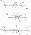
- a method for treating the field operated component 100 includes removing the first portion 106 (see FIG. 1 ) of the field operated component 100, forming a first exposed CMC surface 200 on the field operated component 100.
- a second portion 202 is provided, the second portion 202 also including the CMC 102.
- the second portion 202 includes a second exposed CMC surface 204 having a conformation 206 adapted to mate with the first exposed CMC surface 200.
- the second portion 200 may be repurposed from another field operated component, may be repurposed from a component which has not been previously operated, or may be an incomplete component, specifically fabricated for use in replacing the first portion 106 or utilized opportunistically to replace the first portion 106.
- the second portion 202 is positioned in association with the field operated component 100 so as to replace the first portion 106.
- the second portion 202 is joined at joint 302 to the field operated component 100 to form a treated component 300, wherein each of the field operated component 100 and the second portion 202 includes a ceramic matrix composite 102.
- a joining material 400 may be applied to at least one of the first exposed CMC surface 200 and the second exposed CMC surface 204 during the joining of the field operated component 100 to the second portion 202.
- the joining material 400 may include any suitable composition, including, but not limited to, a joining slurry, a fiber reinforced joining slurry, a matrix ply 500 ( see FIG. 5 ), at least one layer of unidirectional tape 502 ( see FIG. 5 ), or combinations thereof.
- the joining material 400 includes any suitable material, including, but not limited to, a carbon source, elemental carbon, a hydrocarbon, an alcohol, silicon carbide, or a combination thereof.
- joining the second portion 202 and the field operated component 100 includes placing the field operated component 100 and the second portion 202 in a fixture, applying the joining material 400 to at least one of the first exposed CMC surface 200 and the second exposed CMC surface 204, and drying the joining material 400 under a vacuum.
- joining the second portion 202 and the field operated component 100 may include adding at least one matrix ply 500 over the joint 302 defined by the first exposed CMC surface 200 and the second exposed CMC surface 204.
- Joining the second portion 202 and the field operated component 106 may further include densifying the at least one fiber reinforced ply 500, the second portion 202 and the field operated component 100. Densifying may include, but is not limited to, melting silicon into a portion of the at least one matrix ply 500, the second portion 202 and the field operated component 100, and reacting the silicon with a carbon source to form silicon carbide, thus solidifying the at least one matrix ply 500, the second portion 202 and the field operated component 100.
- At least one layer of unidirectional tape 502 is disposed between the at least one matrix ply 500 and the joint 302.
- the at least one layer of unidirectional tape 502 includes a plurality of alternating layers of unidirectional ceramic matrix composite tape, each of the plurality of alternating layers alternating fiber orientation at 90° intervals.
- the at least one layer of unidirectional tape 502 includes a plurality of alternating layers of unidirectional ceramic matrix composite tape, each of the plurality of alternating layers alternating fiber orientation at 45° intervals.
- adding the at least one matrix ply 500 and the at least one layer of unidirectional tape 502 includes forming an inset depth 506 in the field operated component 100 and the second portion 202 about equal to a height 504 of the at least one fiber reinforced ply 500 and the at least one layer of unidirectional tape 502. Densifying may further include, densifying the at least one layer of unidirectional tape 502.
- joining the second portion 202 and the field operated component 100 includes applying a joining material 400 to at least one of the first exposed CMC surface 200 and the second exposed CMC surface 204 and adding at least one fiber matrix ply 500 and the at least one unidirectional tape 502 over the joint 302 defined by the first exposed CMC surface 200 and the second exposed CMC surface 204.
- Joining the second portion 202 and the field operated component 100 may include any suitable technique, such as, but not limited to, autoclaving, burning out, melt infiltration, local heat treatment, inductive heating, laser heating, or a combination thereof.
- the treated component 300 is subjected to any suitable finishing process, including, but not limited to, machining, polishing, coating or a combination thereof.
- treating the field operated component 100 includes removing a first environmental barrier coating from the field operated component 100. In another embodiment, treating the field operated component 100 includes applying a second environmental bond coating to the treated component 300.
- the joint may be any suitable joint, including, but not limited to, a butt joint, a bridle joint, a dowel joint, a miter joint, a finger joint, a dovetail joint, a dado joint, a groove joint, a tongue and groove joint, a mortise and tenon joint, a hammer-headed tenon joint, a birdsmouth joint, a lap joint, an end lap joint, a half lap joint, a cross lap joint, a dovetail lap joint, a dovetail crossed lap, a mitred half lap joint, a halved joint, a splice joint, a half lap splice joint, a bevel lap splice joint, a tabled splice joint, a tapered finger splice joint, a wedged tabled spice joint, a
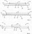
- the joint 302 is a plain scarfed joint 600.
- the joint 302 is a nibbed scarfed joint 700.
- the joint 302 may be a half-lap splice joint 800.
- the joint 302 is a bevel lap splice joint 900.
- the joint 302 is a tabled splice joint 1000.
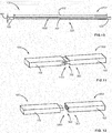
- the joint 302 may be a tongue and groove joint 1100.
- the joint 302 is a mortise and tenon joint 1200.
- the joint 302 is a scarf joint, a plain scarf joint, a nibbed scarf joint, a keyed nibbed scarf joint, a splice joint, a half lap splice joint, a bevel lap splice joint, a tabled splice joint, a tapered finger splice joint, a wedged tabled spice joint or a combination thereof.
- the joint 302 includes a joint width 602 to joint thickness 604 ratio (w/t ratio) between 0 and about 50, alternatively about 10 to about 20, alternatively about 12 to about 18, alternatively about 10 to about 14, alternatively about 13 to about 17, alternatively about 16 to about 20, alternatively about 15.
Landscapes
- Engineering & Computer Science (AREA)
- Mechanical Engineering (AREA)
- Chemical & Material Sciences (AREA)
- General Engineering & Computer Science (AREA)
- Materials Engineering (AREA)
- Ceramic Engineering (AREA)
- Combustion & Propulsion (AREA)
- Composite Materials (AREA)
- Manufacturing & Machinery (AREA)
- Structural Engineering (AREA)
- Organic Chemistry (AREA)
- Turbine Rotor Nozzle Sealing (AREA)
- Ceramic Products (AREA)
Abstract
Description
- The present invention is directed to methods for treating field operated components, and treated components. More particularly, the present invention is directed to methods for replacing a portion of a field operated component, and treated components having a replaced portion.
- Gas turbines are continuously being modified to provide increased efficiency and performance. These modifications include the ability to operate at higher temperatures and under harsher conditions, which often requires material modifications and/or coatings to protect components from such temperatures and conditions. As more modifications are introduced, additional challenges are realized.
- One modification to increase performance and efficiency involves forming gas turbine components, such as, but not limited to, shrouds, turbine struts, nozzles/vanes, combustion liners, buckets/blades, shroud rings, exhaust ducts, augmentation liners, and jet exhaust nozzles from a ceramic matrix composite (CMC). CMC turbine components may be subject to degradation in a combustion flow field due to interactions of the CMC with combustion gases, include water, at elevated temperatures. CMC turbine components may also be subject to mechanical or other damage under operating conditions. However, CMC components for gas turbines and other systems may be expensive, and replacing an entire component as a result of localized damage or wear and tear is economically disadvantageous.
- In an exemplary embodiment, a method for treating a field operated component includes providing the field operated component including a ceramic matrix composite and removing a first portion of the field operated component, forming a first exposed ceramic matrix composite surface on the field operated component. The method further includes providing a second portion including the ceramic matrix composite, the second portion having a second exposed ceramic matrix composite surface including a conformation adapted to mate with the first exposed ceramic matrix composite surface. The second portion is positioned in association with the field operated component so as to replace the first portion, and the second portion and the field operated component are joined to form a treated component.
- In another exemplary embodiment, a method for treating a field operated turbine component selected from the group consisting of a shroud, a turbine strut, a nozzle, a combustion liner, a bucket, a shroud ring, an exhaust duct, an augmentation liner, a jet exhaust nozzle, and combinations thereof, includes providing the field operated turbine component including a ceramic matrix composite, removing a first environmental barrier coating from the field operated turbine component, and removing a first portion of the field operated turbine component, forming a first exposed ceramic matrix composite surface on the field operated turbine component. The method further includes providing a second portion including the ceramic matrix composite, the second portion having a second exposed ceramic matrix composite surface including a conformation adapted to mate with the first exposed ceramic matrix composite surface. The second portion is positioned in association with the field operated turbine component so as to replace the first portion. The first exposed ceramic matrix composite surface and the second exposed ceramic matrix composite surface are arranged and conformed to define a joint. The second portion and the field operated turbine component are joined to form a treated turbine component, and a second environmental barrier coating is applied to the treated turbine component.
- Other features and advantages of the present invention will be apparent from the following more detailed description of the preferred embodiment, taken in conjunction with the accompanying drawings, which illustrate, by way of example, the principles of the invention.
-
-
FIG. 1 is a perspective view of a field operated component, according to an embodiment of the present disclosure. -
FIG. 2 is a perspective view of the field operated component ofFIG. 1 following removal of a first portion in preparation for replacement of the first portion with a second portion, according to an embodiment of the present disclosure. -
FIG. 3 is a perspective view of a treated component, following replacement of the first portion of the field operated component ofFIG. 1 with the second portion ofFIG. 2 , according to an embodiment of the present disclosure. -
FIG. 4 is a side view of a field operated component following removal of a first portion in preparation for replacement of the first portion with a second portion, according to an embodiment of the present disclosure. -
FIG. 5 is a side view of a treated component, following replacement of a first portion of the field operated component with a second portion, according to an embodiment of the present disclosure. -
FIG. 6 is a side view of a treated component, following replacement of a first portion of the field operated component with a second portion by a plain scarfed joint, according to an embodiment of the present disclosure. -
FIG. 7 is a side view of a treated component, following replacement of a first portion of the field operated component with a second portion by a nibbed scarfed joint, according to an embodiment of the present disclosure. -
FIG. 8 is a side view of a treated component, following replacement of a first portion of the field operated component with a second portion by a half lap splice joint, according to an embodiment of the present disclosure. -
FIG. 9 is a side view of a treated component, following replacement of a first portion of the field operated component with a second portion by a bevel lap splice joint, according to an embodiment of the present disclosure. -
FIG. 10 is a side view of a treated component, following replacement of a first portion of the field operated component with a second portion by a tabled splice joint, according to an embodiment of the present disclosure. -
FIG. 11 is a side view of a treated component, following replacement of a first portion of the field operated component with a second portion by a tongue and groove joint, according to an embodiment of the present disclosure. -
FIG. 12 is a side view of a treated component, following replacement of a first portion of the field operated component with a second portion by a mortise and tenon joint, according to an embodiment of the present disclosure. - Wherever possible, the same reference numbers will be used throughout the drawings to represent the same parts.
- Provided are exemplary components, gas turbine components and methods of forming components and gas turbine components. Embodiments of the present disclosure, in comparison to methods and products not utilizing one or more features disclosed herein, provide a more cost effective and time-efficient method of extending the useful life of a component.
- Referring to
FIG. 1 , a field operatedcomponent 100 includes a ceramic matrix composite (CMC) 102. The field operatedcomponent 100 further includes a field operatedcondition 104 localized on afirst portion 106 of the field operatedcomponent 100. - The field operated
component 100 may be any component which includes aCMC 102. In one embodiment, the field operatedcomponent 100 is a gas turbine component. In a further embodiment, the field operatedcomponent 100 is a gas turbine component, such as, but not limited to, a shroud, a turbine strut, a nozzle (or vane), a combustion liner, a bucket (or blade), a shroud ring, an exhaust duct, an augmentation liner, a jet exhaust nozzle, or a combination thereof. - Examples of the
CMC 102 include, but are not limited to, carbon-fiber-reinforced carbon (C/C), carbon-fiber-reinforced silicon carbide (C/SiC), silicon-carbide-fiber-reinforced silicon carbide (SiC/SiC), and alumina-fiber-reinforced alumina (Al2O3/Al2O3), and combinations thereof. TheCMC 102 may have increased elongation, fracture toughness, thermal shock, dynamical load capability, and anisotropic properties as compared to a monolithic ceramic structure. - The field operated
condition 104 may include any undesirable or detrimental condition, including, but not limited to, damage, cracking, erosion, corrosion, pitting, wear, delamination, oxidation, strain, fatigue, chemical attack, degradation, spallation, fragmentation, weakness, or a combination thereof. - Referring to
FIG. 2 , a method for treating the field operatedcomponent 100 includes removing the first portion 106 (seeFIG. 1 ) of the field operatedcomponent 100, forming a first exposedCMC surface 200 on the field operatedcomponent 100. Asecond portion 202 is provided, thesecond portion 202 also including theCMC 102. Thesecond portion 202 includes a second exposedCMC surface 204 having aconformation 206 adapted to mate with the first exposedCMC surface 200. Thesecond portion 200 may be repurposed from another field operated component, may be repurposed from a component which has not been previously operated, or may be an incomplete component, specifically fabricated for use in replacing thefirst portion 106 or utilized opportunistically to replace thefirst portion 106. Thesecond portion 202 is positioned in association with the field operatedcomponent 100 so as to replace thefirst portion 106. - Referring to
FIG. 3 , thesecond portion 202 is joined atjoint 302 to the field operatedcomponent 100 to form a treatedcomponent 300, wherein each of the field operatedcomponent 100 and thesecond portion 202 includes aceramic matrix composite 102. - Referring to
FIG. 4 , a joiningmaterial 400 may be applied to at least one of the first exposedCMC surface 200 and the second exposedCMC surface 204 during the joining of the field operatedcomponent 100 to thesecond portion 202. The joiningmaterial 400 may include any suitable composition, including, but not limited to, a joining slurry, a fiber reinforced joining slurry, a matrix ply 500 (seeFIG. 5 ), at least one layer of unidirectional tape 502 (seeFIG. 5 ), or combinations thereof. In one embodiment, the joiningmaterial 400 includes any suitable material, including, but not limited to, a carbon source, elemental carbon, a hydrocarbon, an alcohol, silicon carbide, or a combination thereof. In another embodiment, joining thesecond portion 202 and the field operatedcomponent 100 includes placing the field operatedcomponent 100 and thesecond portion 202 in a fixture, applying the joiningmaterial 400 to at least one of the first exposedCMC surface 200 and the second exposedCMC surface 204, and drying the joiningmaterial 400 under a vacuum. - Referring to
FIG. 5 , joining thesecond portion 202 and the field operatedcomponent 100 may include adding at least onematrix ply 500 over thejoint 302 defined by the first exposedCMC surface 200 and the second exposedCMC surface 204. Joining thesecond portion 202 and the field operatedcomponent 106 may further include densifying the at least one fiber reinforcedply 500, thesecond portion 202 and the field operatedcomponent 100. Densifying may include, but is not limited to, melting silicon into a portion of the at least onematrix ply 500, thesecond portion 202 and the field operatedcomponent 100, and reacting the silicon with a carbon source to form silicon carbide, thus solidifying the at least onematrix ply 500, thesecond portion 202 and the field operatedcomponent 100. - In one embodiment, at least one layer of
unidirectional tape 502 is disposed between the at least onematrix ply 500 and thejoint 302. In a further embodiment, the at least one layer ofunidirectional tape 502 includes a plurality of alternating layers of unidirectional ceramic matrix composite tape, each of the plurality of alternating layers alternating fiber orientation at 90° intervals. In another embodiment, the at least one layer ofunidirectional tape 502 includes a plurality of alternating layers of unidirectional ceramic matrix composite tape, each of the plurality of alternating layers alternating fiber orientation at 45° intervals. In yet another embodiment, adding the at least onematrix ply 500 and the at least one layer ofunidirectional tape 502 includes forming aninset depth 506 in the field operatedcomponent 100 and thesecond portion 202 about equal to aheight 504 of the at least one fiber reinforcedply 500 and the at least one layer ofunidirectional tape 502. Densifying may further include, densifying the at least one layer ofunidirectional tape 502. - In one embodiment, joining the
second portion 202 and the field operatedcomponent 100 includes applying a joiningmaterial 400 to at least one of the first exposedCMC surface 200 and the second exposedCMC surface 204 and adding at least onefiber matrix ply 500 and the at least oneunidirectional tape 502 over thejoint 302 defined by the first exposedCMC surface 200 and the second exposedCMC surface 204. - Joining the
second portion 202 and the field operatedcomponent 100 may include any suitable technique, such as, but not limited to, autoclaving, burning out, melt infiltration, local heat treatment, inductive heating, laser heating, or a combination thereof. In one embodiment, following joining, the treatedcomponent 300 is subjected to any suitable finishing process, including, but not limited to, machining, polishing, coating or a combination thereof. - In one embodiment, treating the field operated
component 100 includes removing a first environmental barrier coating from the field operatedcomponent 100. In another embodiment, treating the field operatedcomponent 100 includes applying a second environmental bond coating to the treatedcomponent 300. - Referring to
FIGS. 6-12 , the first exposedCMC surface 200 and the second exposedCMC surface 204 are arranged and conformed to define a joint 302. The joint may be any suitable joint, including, but not limited to, a butt joint, a bridle joint, a dowel joint, a miter joint, a finger joint, a dovetail joint, a dado joint, a groove joint, a tongue and groove joint, a mortise and tenon joint, a hammer-headed tenon joint, a birdsmouth joint, a lap joint, an end lap joint, a half lap joint, a cross lap joint, a dovetail lap joint, a dovetail crossed lap, a mitred half lap joint, a halved joint, a splice joint, a half lap splice joint, a bevel lap splice joint, a tabled splice joint, a tapered finger splice joint, a wedged tabled spice joint, a saddle joint, a crown of thorns joint, a scarf joint, a plain scarf joint, a nibbed scarf joint, a keyed nibbed scarf joint, or a combination thereof. Referring toFIG. 6 , in one embodiment, the joint 302 is a plain scarfed joint 600. Referring toFIG. 7 , in another embodiment, the joint 302 is a nibbed scarfed joint 700. Referring toFIG. 8 , the joint 302 may be a half-lap splice joint 800. Referring toFIG. 9 , in another embodiment, the joint 302 is a bevel lap splice joint 900. Referring toFIG. 10 , in yet another embodiment, the joint 302 is a tabled splice joint 1000. Referring toFIG. 11 , the joint 302 may be a tongue and groove joint 1100. Referring toFIG. 12 , in another embodiment, the joint 302 is a mortise and tenon joint 1200. - Referring to
FIGS. 6-10 , in one embodiment, the joint 302 is a scarf joint, a plain scarf joint, a nibbed scarf joint, a keyed nibbed scarf joint, a splice joint, a half lap splice joint, a bevel lap splice joint, a tabled splice joint, a tapered finger splice joint, a wedged tabled spice joint or a combination thereof. The joint 302 includes ajoint width 602 tojoint thickness 604 ratio (w/t ratio) between 0 and about 50, alternatively about 10 to about 20, alternatively about 12 to about 18, alternatively about 10 to about 14, alternatively about 13 to about 17, alternatively about 16 to about 20, alternatively about 15. - While the invention has been described with reference to a preferred embodiment, it will be understood by those skilled in the art that various changes may be made and equivalents may be substituted for elements thereof without departing from the scope of the invention. In addition, many modifications may be made to adapt a particular situation or material to the teachings of the invention without departing from the essential scope thereof. Therefore, it is intended that the invention not be limited to the particular embodiment disclosed as the best mode contemplated for carrying out this invention, but that the invention will include all embodiments falling within the scope of the appended claims.
Claims (15)
- A method for treating a field operated component (100), the method comprising:providing the field operated component (100) including a ceramic matrix composite (102);removing a first portion (106) of the field operated component (100), forming a first exposed ceramic matrix composite surface (200) on the field operated component (100);providing a second portion (202) including the ceramic matrix composite (102), the second portion (202) having a second exposed ceramic matrix composite surface (204) including a conformation (206) adapted to mate with the first exposed ceramic matrix composite surface (200);positioning the second portion (202) in association with the field operated component (100) so as to replace the first portion (106); andjoining the second portion (202) and the field operated component (100) to form a treated component (300).
- The method of claim 1, wherein the field operated component (100) is a gas turbine component.
- The method of claim 1, wherein the second portion (202) is selected from the group consisting of a repurposed portion of another field operated component, a repurposed portion from a non-operated component, an incomplete component and combinations thereof.
- The method of claim 1, wherein joining the second portion (202) and the field operated component (100) includes
applying a joining material (400), said joining material (400) includes a material selected from the group consisting of a carbon source, elemental carbon, a hydrocarbon, an alcohol, silicon carbide, and a combination thereof to at least one of the first exposed ceramic matrix composite surface (200) and the second exposed ceramic matrix composite surface (204); and
drying the joining material (400) under a vacuum. - The method of claim 1, wherein joining the second portion (202) and the field operated component (100) includes adding at least one matrix ply (500) over a joint (302) defined by the first exposed ceramic matrix composite surface (200) and the second exposed ceramic matrix composite surface (204).
- The method of claim 5, wherein at least one layer of unidirectional tape (502) is disposed between the at least one matrix ply (500) and the joint (302).
- The method of claim 6, wherein the at least one layer of unidirectional tape (502) includes a plurality of alternating layers of unidirectional ceramic matrix composite tape, each of the plurality of alternating layers alternating fiber orientation at 90° intervals.
- The method of claim 6, wherein joining the second portion (202) and the field operated component (100) includes densifying the at least one matrix ply (500), the at least one layer of unidirectional tape (502), the second portion (202) and the field operated component (100).
- The method of claim 6, wherein adding the at least one matrix ply (500) includes forming an inset depth about equal to a height of the at least one matrix ply (500) and the at least one layer of unidirectional tape (502).
- The method of claim 1, wherein the first exposed ceramic matrix composite surface (200) and the second exposed ceramic matrix composite surface (204) are arranged and conformed to define a joint (302), wherein the joint (302) is selected from the group consisting of a scarf joint, a plain scarf joint, a nibbed scarf joint, a keyed nibbed scarf joint, and combinations thereof and wherein the joint (302) includes a w/t ratio between about 0 to about 50.
- The method of claim 1, wherein joining the second portion (202) and the field operated component (100) includes a technique selected from the group consisting of autoclaving, burning out, melt infiltration, local heat treatment, inductive heating, laser heating, and combinations thereof.
- The method of claim 1, wherein the method further includes removing a first environmental barrier coating from the field operated component (100) and/or applying a second environmental bond coating to the treated component (300).
- The method of claim 1, wherein the method further includes machining a surface of the treated component (300).
- A method for treating a field operated turbine component (100), the method comprising:providing the field operated turbine component (100) selected from the group consisting of a shroud, a turbine strut, a nozzle, a combustion liner, a bucket, a shroud ring, an exhaust duct, an augmentation liner, a jet exhaust nozzle, and combinations thereof, the field operated turbine component (100) including a ceramic matrix composite (102);removing a first environmental barrier coating from the field operated turbine component (100);removing a first portion (106) of the field operated turbine component (100), forming a first exposed ceramic matrix composite surface (200) on the field operated turbine component (100);providing a second portion (202) including the ceramic matrix composite (102), the second portion (202) having a second exposed ceramic matrix composite surface (204) including a conformation (206) adapted to mate with the first exposed ceramic matrix composite surface (200);positioning the second portion (202) in association with the field operated turbine component (100) so as to replace the first portion (106), the first exposed ceramic matrix composite surface (200) and the second exposed ceramic matrix composite surface (204) being arranged and conformed to define a joint (302);joining the second portion (202) and the field operated turbine component (100) to form a treated turbine component (300); andapplying a second environmental barrier coating to the treated turbine component (300).
- The method of claim 14, wherein the second portion (202) is selected from the group consisting of a repurposed portion of another field operated turbine component, a repurposed portion from a non-operated turbine component, an incomplete turbine component and combinations thereof.
Applications Claiming Priority (1)
| Application Number | Priority Date | Filing Date | Title |
|---|---|---|---|
| US14/752,186 US9745849B2 (en) | 2015-06-26 | 2015-06-26 | Methods for treating field operated components |
Publications (2)
| Publication Number | Publication Date |
|---|---|
| EP3108994A1 true EP3108994A1 (en) | 2016-12-28 |
| EP3108994B1 EP3108994B1 (en) | 2023-08-09 |
Family
ID=56609659
Family Applications (1)
| Application Number | Title | Priority Date | Filing Date |
|---|---|---|---|
| EP16175272.0A Active EP3108994B1 (en) | 2015-06-26 | 2016-06-20 | Methods for treating field operated components |
Country Status (4)
| Country | Link |
|---|---|
| US (1) | US9745849B2 (en) |
| EP (1) | EP3108994B1 (en) |
| JP (1) | JP6906904B2 (en) |
| CN (1) | CN106437859B (en) |
Families Citing this family (16)
| Publication number | Priority date | Publication date | Assignee | Title |
|---|---|---|---|---|
| ITUA20161718A1 (en) * | 2016-03-16 | 2017-09-16 | Nuovo Pignone Tecnologie Srl | Repair part for a blade assembly of a gas turbine and method for repairing a damaged blade of a blade assembly of a gas turbine |
| US20170276000A1 (en) * | 2016-03-24 | 2017-09-28 | General Electric Company | Apparatus and method for forming apparatus |
| WO2018013594A1 (en) | 2016-07-11 | 2018-01-18 | Apex Biomedical Company, Llc | Chest wall repair device |
| US11187105B2 (en) * | 2017-02-09 | 2021-11-30 | General Electric Company | Apparatus with thermal break |
| US11028696B2 (en) * | 2017-08-07 | 2021-06-08 | General Electric Company | Ceramic matrix composite airfoil repair |
| US11802486B2 (en) | 2017-11-13 | 2023-10-31 | General Electric Company | CMC component and fabrication using mechanical joints |
| US20190284947A1 (en) * | 2018-03-14 | 2019-09-19 | General Electric Company | Cmc shroud segment with interlocking mechanical joints and fabrication |
| US11466580B2 (en) | 2018-05-02 | 2022-10-11 | General Electric Company | CMC nozzle with interlocking mechanical joint and fabrication |
| US10738628B2 (en) * | 2018-05-25 | 2020-08-11 | General Electric Company | Joint for band features on turbine nozzle and fabrication |
| US11459908B2 (en) * | 2018-08-31 | 2022-10-04 | General Electric Company | CMC component including directionally controllable CMC insert and method of fabrication |
| DE102021129747A1 (en) | 2021-11-15 | 2023-05-17 | Arceon B.V. | Fiber ceramic nozzle, use of a fiber ceramic nozzle and method of manufacturing a fiber ceramic nozzle |
| CN115013158B (en) * | 2022-05-23 | 2024-11-26 | 西安鑫垚陶瓷复合材料股份有限公司 | A ceramic-based composite S-shaped narrow space flow channel and its preparation method |
| US12275194B2 (en) | 2023-01-25 | 2025-04-15 | Toyota Motor Engineering & Manufacturing North America, Inc. | Methods for joining unidirectional tapes |
| US20260022075A1 (en) * | 2024-07-17 | 2026-01-22 | General Electric Company | Ceramic matrix composite component manufacturing |
| US12281598B1 (en) * | 2024-07-17 | 2025-04-22 | General Electric Company | Ceramic matrix composite component manufacturing |
| US20260071552A1 (en) * | 2024-09-06 | 2026-03-12 | Rtx Corporation | Lap jointed longitudinal/axial flanges for circumferentially flanged composite components in the form of hollow single/multi-cylinders, single/multi-angle conical frustrums or a combination thereof |
Citations (4)
| Publication number | Priority date | Publication date | Assignee | Title |
|---|---|---|---|---|
| US5928448A (en) * | 1997-11-01 | 1999-07-27 | Northrop Grumman Corporation | Dowel adhesive method for repair of ceramic matrix composites |
| US20080229567A1 (en) * | 2004-01-27 | 2008-09-25 | Boris Bublath | Method for Repairing a Component of a Turbomachine |
| EP2236648A1 (en) * | 2009-03-30 | 2010-10-06 | Alstom Technology Ltd | Comprehensive method for local application and local repair of thermal barrier coatings |
| US20140272248A1 (en) * | 2013-03-15 | 2014-09-18 | Rolls-Royce Corporation | Ceramic matrix composite repair by reactive processing and mechanical interlocking |
Family Cites Families (20)
| Publication number | Priority date | Publication date | Assignee | Title |
|---|---|---|---|---|
| US3802046A (en) | 1972-01-27 | 1974-04-09 | Chromalloy American Corp | Method of making or reconditioning a turbine-nozzle or the like assembly |
| CA989153A (en) | 1972-08-22 | 1976-05-18 | John M. Aartman | Guide vane repair |
| JPH0239469B2 (en) * | 1982-09-10 | 1990-09-05 | Toshiba Ceramics Co | TANKAKEISOZAIRYOYORIPPONSHITSUTEKINIKOSEISARETANETSUKOKANKI |
| US6042880A (en) | 1998-12-22 | 2000-03-28 | General Electric Company | Renewing a thermal barrier coating system |
| US6154959A (en) | 1999-08-16 | 2000-12-05 | Chromalloy Gas Turbine Corporation | Laser cladding a turbine engine vane platform |
| US6820334B2 (en) | 2002-04-19 | 2004-11-23 | General Electric Company | Method for repairing articles of ceramic composites |
| US6905308B2 (en) | 2002-11-20 | 2005-06-14 | General Electric Company | Turbine nozzle segment and method of repairing same |
| US7312274B2 (en) * | 2003-11-24 | 2007-12-25 | General Electric Company | Composition and method for use with ceramic matrix composite T-sections |
| JP2005240776A (en) * | 2004-02-27 | 2005-09-08 | Central Res Inst Of Electric Power Ind | Parts operation plan creation method |
| US7185433B2 (en) | 2004-12-17 | 2007-03-06 | General Electric Company | Turbine nozzle segment and method of repairing same |
| US7628878B2 (en) * | 2005-01-24 | 2009-12-08 | Coi Ceramics, Inc. | Ceramic material suitable for repair of a space vehicle component in a microgravity and vacuum environment, method of making same, and method of repairing a space vehicle component |
| US8205334B2 (en) * | 2005-07-15 | 2012-06-26 | United Technologies Corporation | Method for repairing a gas turbine engine component |
| US7686577B2 (en) | 2006-11-02 | 2010-03-30 | Siemens Energy, Inc. | Stacked laminate fiber wrapped segment |
| JP2008274101A (en) * | 2007-04-27 | 2008-11-13 | Tokai Univ | Adhesive composition for silicon carbide ceramics and method for bonding silicon carbide ceramics |
| US20100126014A1 (en) * | 2008-11-26 | 2010-05-27 | General Electric Company | Repair method for tbc coated turbine components |
| US10654246B2 (en) * | 2012-04-28 | 2020-05-19 | General Electric Company | Composite article and methods therefor |
| US9810069B2 (en) * | 2012-07-02 | 2017-11-07 | Ansaldo Energia Switzerland AG | Repair of a shrouded blade |
| US20140099484A1 (en) * | 2012-10-04 | 2014-04-10 | General Electric Company | Ceramic matrix composite, method of making a ceramic matrix composite, and a pre-preg composite ply |
| JP6004899B2 (en) * | 2012-11-06 | 2016-10-12 | 三菱日立パワーシステムズ株式会社 | Gas turbine member surface inspection method |
| BR112015022447A8 (en) * | 2013-03-13 | 2019-11-26 | Dsm Ip Assets Bv | lightweight semi rigid antiballistic composite systems with engineered compliance and speed sensitive impact response |
-
2015
- 2015-06-26 US US14/752,186 patent/US9745849B2/en active Active
-
2016
- 2016-06-20 EP EP16175272.0A patent/EP3108994B1/en active Active
- 2016-06-24 CN CN201610466731.4A patent/CN106437859B/en active Active
- 2016-06-24 JP JP2016125049A patent/JP6906904B2/en active Active
Patent Citations (4)
| Publication number | Priority date | Publication date | Assignee | Title |
|---|---|---|---|---|
| US5928448A (en) * | 1997-11-01 | 1999-07-27 | Northrop Grumman Corporation | Dowel adhesive method for repair of ceramic matrix composites |
| US20080229567A1 (en) * | 2004-01-27 | 2008-09-25 | Boris Bublath | Method for Repairing a Component of a Turbomachine |
| EP2236648A1 (en) * | 2009-03-30 | 2010-10-06 | Alstom Technology Ltd | Comprehensive method for local application and local repair of thermal barrier coatings |
| US20140272248A1 (en) * | 2013-03-15 | 2014-09-18 | Rolls-Royce Corporation | Ceramic matrix composite repair by reactive processing and mechanical interlocking |
Also Published As
| Publication number | Publication date |
|---|---|
| JP6906904B2 (en) | 2021-07-21 |
| US20160376893A1 (en) | 2016-12-29 |
| JP2017052685A (en) | 2017-03-16 |
| EP3108994B1 (en) | 2023-08-09 |
| CN106437859A (en) | 2017-02-22 |
| US9745849B2 (en) | 2017-08-29 |
| CN106437859B (en) | 2020-10-27 |
Similar Documents
| Publication | Publication Date | Title |
|---|---|---|
| US9745849B2 (en) | Methods for treating field operated components | |
| EP3617450B1 (en) | Cmc component including directionally controllable cmc insert and method of fabrication | |
| JP6730034B2 (en) | CMC turbine component and method of forming CMC turbine component | |
| JP6888933B2 (en) | Ceramic Matrix Composite Components and Methods for Manufacturing Ceramic Matrix Composite Components | |
| US10465534B2 (en) | Machinable CMC insert | |
| US10458653B2 (en) | Machinable CMC insert | |
| US10995623B2 (en) | Ceramic matrix composite turbine blade with abrasive tip | |
| JP7110313B2 (en) | Ceramic matrix composite component containing cooling channels and method of making same | |
| US10401028B2 (en) | Machinable CMC insert | |
| US10472976B2 (en) | Machinable CMC insert | |
| US20100136258A1 (en) | Method for improved ceramic coating | |
| EP3640360B1 (en) | Method of manufacturing a geometrically segmented abradable ceramic thermal barrier coating with improved spallation resistance | |
| US11021971B2 (en) | CMC blade with monolithic ceramic platform and dovetail | |
| US11802486B2 (en) | CMC component and fabrication using mechanical joints | |
| US11028696B2 (en) | Ceramic matrix composite airfoil repair | |
| EP3228829A1 (en) | Apparatus and method for forming apparatus | |
| US10533432B2 (en) | Preform CMC article, CMC article, and method for forming CMC article | |
| CN103588504B (en) | Crack-resistant environmental barrier coatings | |
| US20190257207A1 (en) | Hollow ceramic matrix composite article, mandrel for forming hollow ceramic matrix composite article, and method for forming hollow ceramic matrix composite article |
Legal Events
| Date | Code | Title | Description |
|---|---|---|---|
| PUAI | Public reference made under article 153(3) epc to a published international application that has entered the european phase |
Free format text: ORIGINAL CODE: 0009012 |
|
| STAA | Information on the status of an ep patent application or granted ep patent |
Free format text: STATUS: THE APPLICATION HAS BEEN PUBLISHED |
|
| AK | Designated contracting states |
Kind code of ref document: A1 Designated state(s): AL AT BE BG CH CY CZ DE DK EE ES FI FR GB GR HR HU IE IS IT LI LT LU LV MC MK MT NL NO PL PT RO RS SE SI SK SM TR |
|
| AX | Request for extension of the european patent |
Extension state: BA ME |
|
| STAA | Information on the status of an ep patent application or granted ep patent |
Free format text: STATUS: REQUEST FOR EXAMINATION WAS MADE |
|
| 17P | Request for examination filed |
Effective date: 20170628 |
|
| RBV | Designated contracting states (corrected) |
Designated state(s): AL AT BE BG CH CY CZ DE DK EE ES FI FR GB GR HR HU IE IS IT LI LT LU LV MC MK MT NL NO PL PT RO RS SE SI SK SM TR |
|
| STAA | Information on the status of an ep patent application or granted ep patent |
Free format text: STATUS: EXAMINATION IS IN PROGRESS |
|
| 17Q | First examination report despatched |
Effective date: 20210322 |
|
| RIC1 | Information provided on ipc code assigned before grant |
Ipc: B29C 73/04 20060101ALN20230406BHEP Ipc: F01D 5/28 20060101ALI20230406BHEP Ipc: C04B 37/00 20060101ALI20230406BHEP Ipc: B28B 1/00 20060101ALI20230406BHEP Ipc: F01D 5/00 20060101ALI20230406BHEP Ipc: B23P 6/00 20060101AFI20230406BHEP |
|
| GRAP | Despatch of communication of intention to grant a patent |
Free format text: ORIGINAL CODE: EPIDOSNIGR1 |
|
| STAA | Information on the status of an ep patent application or granted ep patent |
Free format text: STATUS: GRANT OF PATENT IS INTENDED |
|
| INTG | Intention to grant announced |
Effective date: 20230517 |
|
| GRAS | Grant fee paid |
Free format text: ORIGINAL CODE: EPIDOSNIGR3 |
|
| GRAA | (expected) grant |
Free format text: ORIGINAL CODE: 0009210 |
|
| STAA | Information on the status of an ep patent application or granted ep patent |
Free format text: STATUS: THE PATENT HAS BEEN GRANTED |
|
| AK | Designated contracting states |
Kind code of ref document: B1 Designated state(s): AL AT BE BG CH CY CZ DE DK EE ES FI FR GB GR HR HU IE IS IT LI LT LU LV MC MK MT NL NO PL PT RO RS SE SI SK SM TR |
|
| REG | Reference to a national code |
Ref country code: GB Ref legal event code: FG4D |
|
| REG | Reference to a national code |
Ref country code: CH Ref legal event code: EP |
|
| REG | Reference to a national code |
Ref country code: IE Ref legal event code: FG4D |
|
| REG | Reference to a national code |
Ref country code: DE Ref legal event code: R096 Ref document number: 602016081729 Country of ref document: DE |
|
| REG | Reference to a national code |
Ref country code: DE Ref legal event code: R081 Ref document number: 602016081729 Country of ref document: DE Owner name: GENERAL ELECTRIC TECHNOLOGY GMBH, CH Free format text: FORMER OWNER: GENERAL ELECTRIC COMPANY, SCHENECTADY, NY, US |
|
| REG | Reference to a national code |
Ref country code: LT Ref legal event code: MG9D |
|
| RAP2 | Party data changed (patent owner data changed or rights of a patent transferred) |
Owner name: GENERAL ELECTRIC TECHNOLOGY GMBH |
|
| REG | Reference to a national code |
Ref country code: NL Ref legal event code: MP Effective date: 20230809 |
|
| REG | Reference to a national code |
Ref country code: AT Ref legal event code: MK05 Ref document number: 1596939 Country of ref document: AT Kind code of ref document: T Effective date: 20230809 |
|
| PG25 | Lapsed in a contracting state [announced via postgrant information from national office to epo] |
Ref country code: GR Free format text: LAPSE BECAUSE OF FAILURE TO SUBMIT A TRANSLATION OF THE DESCRIPTION OR TO PAY THE FEE WITHIN THE PRESCRIBED TIME-LIMIT Effective date: 20231110 |
|
| PG25 | Lapsed in a contracting state [announced via postgrant information from national office to epo] |
Ref country code: IS Free format text: LAPSE BECAUSE OF FAILURE TO SUBMIT A TRANSLATION OF THE DESCRIPTION OR TO PAY THE FEE WITHIN THE PRESCRIBED TIME-LIMIT Effective date: 20231209 |
|
| PG25 | Lapsed in a contracting state [announced via postgrant information from national office to epo] |
Ref country code: SE Free format text: LAPSE BECAUSE OF FAILURE TO SUBMIT A TRANSLATION OF THE DESCRIPTION OR TO PAY THE FEE WITHIN THE PRESCRIBED TIME-LIMIT Effective date: 20230809 Ref country code: RS Free format text: LAPSE BECAUSE OF FAILURE TO SUBMIT A TRANSLATION OF THE DESCRIPTION OR TO PAY THE FEE WITHIN THE PRESCRIBED TIME-LIMIT Effective date: 20230809 Ref country code: PT Free format text: LAPSE BECAUSE OF FAILURE TO SUBMIT A TRANSLATION OF THE DESCRIPTION OR TO PAY THE FEE WITHIN THE PRESCRIBED TIME-LIMIT Effective date: 20231211 Ref country code: NO Free format text: LAPSE BECAUSE OF FAILURE TO SUBMIT A TRANSLATION OF THE DESCRIPTION OR TO PAY THE FEE WITHIN THE PRESCRIBED TIME-LIMIT Effective date: 20231109 Ref country code: NL Free format text: LAPSE BECAUSE OF FAILURE TO SUBMIT A TRANSLATION OF THE DESCRIPTION OR TO PAY THE FEE WITHIN THE PRESCRIBED TIME-LIMIT Effective date: 20230809 Ref country code: LV Free format text: LAPSE BECAUSE OF FAILURE TO SUBMIT A TRANSLATION OF THE DESCRIPTION OR TO PAY THE FEE WITHIN THE PRESCRIBED TIME-LIMIT Effective date: 20230809 Ref country code: LT Free format text: LAPSE BECAUSE OF FAILURE TO SUBMIT A TRANSLATION OF THE DESCRIPTION OR TO PAY THE FEE WITHIN THE PRESCRIBED TIME-LIMIT Effective date: 20230809 Ref country code: IS Free format text: LAPSE BECAUSE OF FAILURE TO SUBMIT A TRANSLATION OF THE DESCRIPTION OR TO PAY THE FEE WITHIN THE PRESCRIBED TIME-LIMIT Effective date: 20231209 Ref country code: HR Free format text: LAPSE BECAUSE OF FAILURE TO SUBMIT A TRANSLATION OF THE DESCRIPTION OR TO PAY THE FEE WITHIN THE PRESCRIBED TIME-LIMIT Effective date: 20230809 Ref country code: GR Free format text: LAPSE BECAUSE OF FAILURE TO SUBMIT A TRANSLATION OF THE DESCRIPTION OR TO PAY THE FEE WITHIN THE PRESCRIBED TIME-LIMIT Effective date: 20231110 Ref country code: FI Free format text: LAPSE BECAUSE OF FAILURE TO SUBMIT A TRANSLATION OF THE DESCRIPTION OR TO PAY THE FEE WITHIN THE PRESCRIBED TIME-LIMIT Effective date: 20230809 Ref country code: AT Free format text: LAPSE BECAUSE OF FAILURE TO SUBMIT A TRANSLATION OF THE DESCRIPTION OR TO PAY THE FEE WITHIN THE PRESCRIBED TIME-LIMIT Effective date: 20230809 |
|
| PG25 | Lapsed in a contracting state [announced via postgrant information from national office to epo] |
Ref country code: PL Free format text: LAPSE BECAUSE OF FAILURE TO SUBMIT A TRANSLATION OF THE DESCRIPTION OR TO PAY THE FEE WITHIN THE PRESCRIBED TIME-LIMIT Effective date: 20230809 |
|
| REG | Reference to a national code |
Ref country code: GB Ref legal event code: 732E Free format text: REGISTERED BETWEEN 20240222 AND 20240228 |
|
| PG25 | Lapsed in a contracting state [announced via postgrant information from national office to epo] |
Ref country code: ES Free format text: LAPSE BECAUSE OF FAILURE TO SUBMIT A TRANSLATION OF THE DESCRIPTION OR TO PAY THE FEE WITHIN THE PRESCRIBED TIME-LIMIT Effective date: 20230809 |
|
| PG25 | Lapsed in a contracting state [announced via postgrant information from national office to epo] |
Ref country code: SM Free format text: LAPSE BECAUSE OF FAILURE TO SUBMIT A TRANSLATION OF THE DESCRIPTION OR TO PAY THE FEE WITHIN THE PRESCRIBED TIME-LIMIT Effective date: 20230809 Ref country code: RO Free format text: LAPSE BECAUSE OF FAILURE TO SUBMIT A TRANSLATION OF THE DESCRIPTION OR TO PAY THE FEE WITHIN THE PRESCRIBED TIME-LIMIT Effective date: 20230809 Ref country code: ES Free format text: LAPSE BECAUSE OF FAILURE TO SUBMIT A TRANSLATION OF THE DESCRIPTION OR TO PAY THE FEE WITHIN THE PRESCRIBED TIME-LIMIT Effective date: 20230809 Ref country code: EE Free format text: LAPSE BECAUSE OF FAILURE TO SUBMIT A TRANSLATION OF THE DESCRIPTION OR TO PAY THE FEE WITHIN THE PRESCRIBED TIME-LIMIT Effective date: 20230809 Ref country code: DK Free format text: LAPSE BECAUSE OF FAILURE TO SUBMIT A TRANSLATION OF THE DESCRIPTION OR TO PAY THE FEE WITHIN THE PRESCRIBED TIME-LIMIT Effective date: 20230809 Ref country code: CZ Free format text: LAPSE BECAUSE OF FAILURE TO SUBMIT A TRANSLATION OF THE DESCRIPTION OR TO PAY THE FEE WITHIN THE PRESCRIBED TIME-LIMIT Effective date: 20230809 Ref country code: SK Free format text: LAPSE BECAUSE OF FAILURE TO SUBMIT A TRANSLATION OF THE DESCRIPTION OR TO PAY THE FEE WITHIN THE PRESCRIBED TIME-LIMIT Effective date: 20230809 |
|
| REG | Reference to a national code |
Ref country code: DE Ref legal event code: R097 Ref document number: 602016081729 Country of ref document: DE |
|
| PLBE | No opposition filed within time limit |
Free format text: ORIGINAL CODE: 0009261 |
|
| STAA | Information on the status of an ep patent application or granted ep patent |
Free format text: STATUS: NO OPPOSITION FILED WITHIN TIME LIMIT |
|
| 26N | No opposition filed |
Effective date: 20240513 |
|
| PG25 | Lapsed in a contracting state [announced via postgrant information from national office to epo] |
Ref country code: SI Free format text: LAPSE BECAUSE OF FAILURE TO SUBMIT A TRANSLATION OF THE DESCRIPTION OR TO PAY THE FEE WITHIN THE PRESCRIBED TIME-LIMIT Effective date: 20230809 |
|
| PG25 | Lapsed in a contracting state [announced via postgrant information from national office to epo] |
Ref country code: BG Free format text: LAPSE BECAUSE OF FAILURE TO SUBMIT A TRANSLATION OF THE DESCRIPTION OR TO PAY THE FEE WITHIN THE PRESCRIBED TIME-LIMIT Effective date: 20230809 |
|
| PG25 | Lapsed in a contracting state [announced via postgrant information from national office to epo] |
Ref country code: BG Free format text: LAPSE BECAUSE OF FAILURE TO SUBMIT A TRANSLATION OF THE DESCRIPTION OR TO PAY THE FEE WITHIN THE PRESCRIBED TIME-LIMIT Effective date: 20230809 |
|
| PG25 | Lapsed in a contracting state [announced via postgrant information from national office to epo] |
Ref country code: MC Free format text: LAPSE BECAUSE OF FAILURE TO SUBMIT A TRANSLATION OF THE DESCRIPTION OR TO PAY THE FEE WITHIN THE PRESCRIBED TIME-LIMIT Effective date: 20230809 |
|
| REG | Reference to a national code |
Ref country code: CH Ref legal event code: PL |
|
| PG25 | Lapsed in a contracting state [announced via postgrant information from national office to epo] |
Ref country code: LU Free format text: LAPSE BECAUSE OF NON-PAYMENT OF DUE FEES Effective date: 20240620 |
|
| PG25 | Lapsed in a contracting state [announced via postgrant information from national office to epo] |
Ref country code: IE Free format text: LAPSE BECAUSE OF NON-PAYMENT OF DUE FEES Effective date: 20240620 |
|
| PG25 | Lapsed in a contracting state [announced via postgrant information from national office to epo] |
Ref country code: CH Free format text: LAPSE BECAUSE OF NON-PAYMENT OF DUE FEES Effective date: 20240630 Ref country code: BE Free format text: LAPSE BECAUSE OF NON-PAYMENT OF DUE FEES Effective date: 20240630 |
|
| REG | Reference to a national code |
Ref country code: BE Ref legal event code: MM Effective date: 20240630 |
|
| PGFP | Annual fee paid to national office [announced via postgrant information from national office to epo] |
Ref country code: DE Payment date: 20250520 Year of fee payment: 10 |
|
| PGFP | Annual fee paid to national office [announced via postgrant information from national office to epo] |
Ref country code: GB Payment date: 20250520 Year of fee payment: 10 |
|
| PGFP | Annual fee paid to national office [announced via postgrant information from national office to epo] |
Ref country code: IT Payment date: 20250520 Year of fee payment: 10 |
|
| PGFP | Annual fee paid to national office [announced via postgrant information from national office to epo] |
Ref country code: FR Payment date: 20250520 Year of fee payment: 10 |
|
| PG25 | Lapsed in a contracting state [announced via postgrant information from national office to epo] |
Ref country code: CY Free format text: LAPSE BECAUSE OF FAILURE TO SUBMIT A TRANSLATION OF THE DESCRIPTION OR TO PAY THE FEE WITHIN THE PRESCRIBED TIME-LIMIT; INVALID AB INITIO Effective date: 20160620 |
|
| PG25 | Lapsed in a contracting state [announced via postgrant information from national office to epo] |
Ref country code: HU Free format text: LAPSE BECAUSE OF FAILURE TO SUBMIT A TRANSLATION OF THE DESCRIPTION OR TO PAY THE FEE WITHIN THE PRESCRIBED TIME-LIMIT; INVALID AB INITIO Effective date: 20160620 |